EP1777687A1 - Plasma display apparatus - Google Patents
Plasma display apparatus Download PDFInfo
- Publication number
- EP1777687A1 EP1777687A1 EP06291638A EP06291638A EP1777687A1 EP 1777687 A1 EP1777687 A1 EP 1777687A1 EP 06291638 A EP06291638 A EP 06291638A EP 06291638 A EP06291638 A EP 06291638A EP 1777687 A1 EP1777687 A1 EP 1777687A1
- Authority
- EP
- European Patent Office
- Prior art keywords
- voltage
- plasma display
- duration
- display apparatus
- time
- Prior art date
- Legal status (The legal status is an assumption and is not a legal conclusion. Google has not performed a legal analysis and makes no representation as to the accuracy of the status listed.)
- Withdrawn
Links
- 230000000630 rising effect Effects 0.000 claims description 9
- 239000003990 capacitor Substances 0.000 description 14
- 238000011084 recovery Methods 0.000 description 5
- 230000007423 decrease Effects 0.000 description 3
- 238000004519 manufacturing process Methods 0.000 description 3
- 239000011261 inert gas Substances 0.000 description 2
- OAICVXFJPJFONN-UHFFFAOYSA-N Phosphorus Chemical compound [P] OAICVXFJPJFONN-UHFFFAOYSA-N 0.000 description 1
- 230000004888 barrier function Effects 0.000 description 1
- 239000007789 gas Substances 0.000 description 1
- 230000004048 modification Effects 0.000 description 1
- 238000012986 modification Methods 0.000 description 1
Images


Classifications
-
- G—PHYSICS
- G09—EDUCATION; CRYPTOGRAPHY; DISPLAY; ADVERTISING; SEALS
- G09G—ARRANGEMENTS OR CIRCUITS FOR CONTROL OF INDICATING DEVICES USING STATIC MEANS TO PRESENT VARIABLE INFORMATION
- G09G3/00—Control arrangements or circuits, of interest only in connection with visual indicators other than cathode-ray tubes
- G09G3/20—Control arrangements or circuits, of interest only in connection with visual indicators other than cathode-ray tubes for presentation of an assembly of a number of characters, e.g. a page, by composing the assembly by combination of individual elements arranged in a matrix no fixed position being assigned to or needed to be assigned to the individual characters or partial characters
- G09G3/22—Control arrangements or circuits, of interest only in connection with visual indicators other than cathode-ray tubes for presentation of an assembly of a number of characters, e.g. a page, by composing the assembly by combination of individual elements arranged in a matrix no fixed position being assigned to or needed to be assigned to the individual characters or partial characters using controlled light sources
- G09G3/28—Control arrangements or circuits, of interest only in connection with visual indicators other than cathode-ray tubes for presentation of an assembly of a number of characters, e.g. a page, by composing the assembly by combination of individual elements arranged in a matrix no fixed position being assigned to or needed to be assigned to the individual characters or partial characters using controlled light sources using luminous gas-discharge panels, e.g. plasma panels
- G09G3/288—Control arrangements or circuits, of interest only in connection with visual indicators other than cathode-ray tubes for presentation of an assembly of a number of characters, e.g. a page, by composing the assembly by combination of individual elements arranged in a matrix no fixed position being assigned to or needed to be assigned to the individual characters or partial characters using controlled light sources using luminous gas-discharge panels, e.g. plasma panels using AC panels
- G09G3/296—Driving circuits for producing the waveforms applied to the driving electrodes
-
- G—PHYSICS
- G09—EDUCATION; CRYPTOGRAPHY; DISPLAY; ADVERTISING; SEALS
- G09G—ARRANGEMENTS OR CIRCUITS FOR CONTROL OF INDICATING DEVICES USING STATIC MEANS TO PRESENT VARIABLE INFORMATION
- G09G3/00—Control arrangements or circuits, of interest only in connection with visual indicators other than cathode-ray tubes
- G09G3/20—Control arrangements or circuits, of interest only in connection with visual indicators other than cathode-ray tubes for presentation of an assembly of a number of characters, e.g. a page, by composing the assembly by combination of individual elements arranged in a matrix no fixed position being assigned to or needed to be assigned to the individual characters or partial characters
- G09G3/22—Control arrangements or circuits, of interest only in connection with visual indicators other than cathode-ray tubes for presentation of an assembly of a number of characters, e.g. a page, by composing the assembly by combination of individual elements arranged in a matrix no fixed position being assigned to or needed to be assigned to the individual characters or partial characters using controlled light sources
- G09G3/28—Control arrangements or circuits, of interest only in connection with visual indicators other than cathode-ray tubes for presentation of an assembly of a number of characters, e.g. a page, by composing the assembly by combination of individual elements arranged in a matrix no fixed position being assigned to or needed to be assigned to the individual characters or partial characters using controlled light sources using luminous gas-discharge panels, e.g. plasma panels
- G09G3/288—Control arrangements or circuits, of interest only in connection with visual indicators other than cathode-ray tubes for presentation of an assembly of a number of characters, e.g. a page, by composing the assembly by combination of individual elements arranged in a matrix no fixed position being assigned to or needed to be assigned to the individual characters or partial characters using controlled light sources using luminous gas-discharge panels, e.g. plasma panels using AC panels
- G09G3/291—Control arrangements or circuits, of interest only in connection with visual indicators other than cathode-ray tubes for presentation of an assembly of a number of characters, e.g. a page, by composing the assembly by combination of individual elements arranged in a matrix no fixed position being assigned to or needed to be assigned to the individual characters or partial characters using controlled light sources using luminous gas-discharge panels, e.g. plasma panels using AC panels controlling the gas discharge to control a cell condition, e.g. by means of specific pulse shapes
- G09G3/292—Control arrangements or circuits, of interest only in connection with visual indicators other than cathode-ray tubes for presentation of an assembly of a number of characters, e.g. a page, by composing the assembly by combination of individual elements arranged in a matrix no fixed position being assigned to or needed to be assigned to the individual characters or partial characters using controlled light sources using luminous gas-discharge panels, e.g. plasma panels using AC panels controlling the gas discharge to control a cell condition, e.g. by means of specific pulse shapes for reset discharge, priming discharge or erase discharge occurring in a phase other than addressing
- G09G3/2927—Details of initialising
-
- G—PHYSICS
- G09—EDUCATION; CRYPTOGRAPHY; DISPLAY; ADVERTISING; SEALS
- G09G—ARRANGEMENTS OR CIRCUITS FOR CONTROL OF INDICATING DEVICES USING STATIC MEANS TO PRESENT VARIABLE INFORMATION
- G09G2310/00—Command of the display device
- G09G2310/06—Details of flat display driving waveforms
- G09G2310/066—Waveforms comprising a gently increasing or decreasing portion, e.g. ramp
-
- G—PHYSICS
- G09—EDUCATION; CRYPTOGRAPHY; DISPLAY; ADVERTISING; SEALS
- G09G—ARRANGEMENTS OR CIRCUITS FOR CONTROL OF INDICATING DEVICES USING STATIC MEANS TO PRESENT VARIABLE INFORMATION
- G09G2330/00—Aspects of power supply; Aspects of display protection and defect management
- G09G2330/02—Details of power systems and of start or stop of display operation
- G09G2330/028—Generation of voltages supplied to electrode drivers in a matrix display other than LCD
-
- G—PHYSICS
- G09—EDUCATION; CRYPTOGRAPHY; DISPLAY; ADVERTISING; SEALS
- G09G—ARRANGEMENTS OR CIRCUITS FOR CONTROL OF INDICATING DEVICES USING STATIC MEANS TO PRESENT VARIABLE INFORMATION
- G09G3/00—Control arrangements or circuits, of interest only in connection with visual indicators other than cathode-ray tubes
- G09G3/20—Control arrangements or circuits, of interest only in connection with visual indicators other than cathode-ray tubes for presentation of an assembly of a number of characters, e.g. a page, by composing the assembly by combination of individual elements arranged in a matrix no fixed position being assigned to or needed to be assigned to the individual characters or partial characters
- G09G3/22—Control arrangements or circuits, of interest only in connection with visual indicators other than cathode-ray tubes for presentation of an assembly of a number of characters, e.g. a page, by composing the assembly by combination of individual elements arranged in a matrix no fixed position being assigned to or needed to be assigned to the individual characters or partial characters using controlled light sources
- G09G3/28—Control arrangements or circuits, of interest only in connection with visual indicators other than cathode-ray tubes for presentation of an assembly of a number of characters, e.g. a page, by composing the assembly by combination of individual elements arranged in a matrix no fixed position being assigned to or needed to be assigned to the individual characters or partial characters using controlled light sources using luminous gas-discharge panels, e.g. plasma panels
- G09G3/288—Control arrangements or circuits, of interest only in connection with visual indicators other than cathode-ray tubes for presentation of an assembly of a number of characters, e.g. a page, by composing the assembly by combination of individual elements arranged in a matrix no fixed position being assigned to or needed to be assigned to the individual characters or partial characters using controlled light sources using luminous gas-discharge panels, e.g. plasma panels using AC panels
- G09G3/291—Control arrangements or circuits, of interest only in connection with visual indicators other than cathode-ray tubes for presentation of an assembly of a number of characters, e.g. a page, by composing the assembly by combination of individual elements arranged in a matrix no fixed position being assigned to or needed to be assigned to the individual characters or partial characters using controlled light sources using luminous gas-discharge panels, e.g. plasma panels using AC panels controlling the gas discharge to control a cell condition, e.g. by means of specific pulse shapes
- G09G3/293—Control arrangements or circuits, of interest only in connection with visual indicators other than cathode-ray tubes for presentation of an assembly of a number of characters, e.g. a page, by composing the assembly by combination of individual elements arranged in a matrix no fixed position being assigned to or needed to be assigned to the individual characters or partial characters using controlled light sources using luminous gas-discharge panels, e.g. plasma panels using AC panels controlling the gas discharge to control a cell condition, e.g. by means of specific pulse shapes for address discharge
-
- G—PHYSICS
- G09—EDUCATION; CRYPTOGRAPHY; DISPLAY; ADVERTISING; SEALS
- G09G—ARRANGEMENTS OR CIRCUITS FOR CONTROL OF INDICATING DEVICES USING STATIC MEANS TO PRESENT VARIABLE INFORMATION
- G09G3/00—Control arrangements or circuits, of interest only in connection with visual indicators other than cathode-ray tubes
- G09G3/20—Control arrangements or circuits, of interest only in connection with visual indicators other than cathode-ray tubes for presentation of an assembly of a number of characters, e.g. a page, by composing the assembly by combination of individual elements arranged in a matrix no fixed position being assigned to or needed to be assigned to the individual characters or partial characters
- G09G3/22—Control arrangements or circuits, of interest only in connection with visual indicators other than cathode-ray tubes for presentation of an assembly of a number of characters, e.g. a page, by composing the assembly by combination of individual elements arranged in a matrix no fixed position being assigned to or needed to be assigned to the individual characters or partial characters using controlled light sources
- G09G3/28—Control arrangements or circuits, of interest only in connection with visual indicators other than cathode-ray tubes for presentation of an assembly of a number of characters, e.g. a page, by composing the assembly by combination of individual elements arranged in a matrix no fixed position being assigned to or needed to be assigned to the individual characters or partial characters using controlled light sources using luminous gas-discharge panels, e.g. plasma panels
- G09G3/288—Control arrangements or circuits, of interest only in connection with visual indicators other than cathode-ray tubes for presentation of an assembly of a number of characters, e.g. a page, by composing the assembly by combination of individual elements arranged in a matrix no fixed position being assigned to or needed to be assigned to the individual characters or partial characters using controlled light sources using luminous gas-discharge panels, e.g. plasma panels using AC panels
- G09G3/296—Driving circuits for producing the waveforms applied to the driving electrodes
- G09G3/2965—Driving circuits for producing the waveforms applied to the driving electrodes using inductors for energy recovery
Definitions
- This document relates to a plasma display apparatus.
- a plasma display apparatus comprises a plasma display panel in which a discharge cell is filled with a main discharge gas and an inert gas, and a driver.
- the inert gas When a high frequency voltage is supplied to an electrode of the plasma display panel, the inert gas generates vacuum ultraviolet rays, which thereby cause a phosphor formed between barrier ribs of the plasma display panel to emit light.
- the plasma display apparatus displays an image during each of subfields constituting a frame.
- Each of the subfields comprises a reset period for initializing all the discharge cells, an address period for selecting cells to be discharged and a sustain period for representing gray level in accordance with the number of discharges.
- the reset period comprises a setup period and a set-down period.
- a setup pulse is supplied to scan electrodes.
- the setup pulse generates a weak dark discharge in the discharge cells. This results in wall charges of a positive polarity being accumulated on address electrodes and sustain electrodes, and wall charges of a negative polarity being accumulated on the scan electrodes.
- a set-down pulse is supplied to the scan electrodes. This results in erasing a portion of the wall charges excessively accumulated on the scan electrodes such the remaining wall charges are uniform inside the discharge cells.
- a scan pulse is supplied to the scan electrodes, and a data pulse is supplied to the address electrodes.
- the voltage difference between the scan pulse and the data pulse is added to the wall voltage produced during the reset period, the cells to be discharged are selected.
- a sustain pulse is supplied to the scan electrodes and the sustain electrodes.
- a sustain discharge occurs within the discharge cells selected during the address period, thereby displaying an image.
- the driver of the plasma display apparatus supplies a driving pulse to the electrode of the plasma display panel during the reset period, the address period and the sustain period.
- the driver supplies the setup pulse and the set-down pulse during the reset period, the data pulse and the scan pulse during the address period, and the sustain pulse during the sustain period.
- a plasma display apparatus comprises a plasma display panel comprising an electrode, a voltage controller comprising a switch unit for forming a set-down pulse gradually falling to a first voltage for a first duration of time of a set-down period and for forming the first voltage for a second duration of time of an address period, a scan operating unit for forming a second voltage during the address period, and a driving signal supply unit for supplying the set-down pulse to the electrode during the set-down period, and for supplying the first voltage and the second voltage to the electrode during the address period.
- a plasma display apparatus comprises a plasma display panel comprising an electrode, a voltage controller comprising a switch unit for forming a set-down pulse gradually falling to a first voltage for a first duration of time of a set-down period and for forming the first voltage for a second duration of time of an address period, a scan operating unit comprising a voltage source connected to one terminal of the switch unit for forming a second voltage during the address period, and a driving signal supply unit comprising a first switch unit for supplying the set-down pulse to the electrode during the set-down period and for supplying the first voltage and the second voltage to the electrode during the address period.
- a plasma display apparatus comprises a plasma display panel comprising an electrode, a voltage controller comprising a switch unit for forming a set-down pulse gradually falling to a first voltage for a first duration of time of a set-down period and for forming the first voltage for a second duration of time of an address period, a scan operating unit for forming a second voltage during the address period, a driving signal supply unit for supplying the set-down pulse to the electrode during the set-down period, and for supplying the first voltage and the second voltage to the electrode during the address period, and a controller for outputting a turn-on control signal to the switch unit.
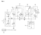
- FIG. 1 illustrates a plasma display apparatus according to an embodiment
- FIG. 2 illustrates a current path during a set-down period in the plasma display apparatus according to the embodiment
- FIG. 3 illustrates a current path during an address period in the plasma display apparatus according to the embodiment.
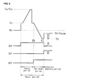
- FIG. 4 illustrates a waveform of a turn-on control signal for forming the current paths illustrated in FIGs. 2 and 3.
- a plasma display apparatus comprises a plasma display panel comprising an electrode, a voltage controller comprising a switch unit for forming a set-down pulse gradually falling to a first voltage for a first duration of time of a set-down period and for forming the first voltage for a second duration of time of an address period, a scan operating unit for forming a second voltage during the address period, and a driving signal supply unit for supplying the set-down pulse to the electrode during the set-down period, and for supplying the first voltage and the second voltage to the electrode during the address period.
- the switch unit may be turned on for the first duration of time and the second duration of time.
- the switch unit may operate in an active region for the first duration of time, and may operate in a saturation region for the second duration of time.
- the driving signal supply unit may supply a scan pulse maintained at the first voltage to the electrode.
- the plasma display apparatus may further comprise a setup controller for forming a setup pulse rising from a sustain voltage to two times the sustain voltage during a setup period.
- a plasma display apparatus comprises a plasma display panel comprising an electrode, a voltage controller comprising a switch unit for forming a set-down pulse gradually falling to a first voltage for a first duration of time of a set-down period and for forming the first voltage for a second duration of time of an address period, a scan operating unit comprising a voltage source connected to one terminal of the switch unit for forming a second voltage during the address period, and a driving signal supply unit comprising a first switch unit for supplying the set-down pulse to the electrode during the set-down period and for supplying the first voltage and the second voltage to the electrode during the address period.
- the switch unit of the voltage controller may be turned on for the first duration of time and the second duration of time.
- the scan operating unit may comprise a switch unit which operates in an active region for the first duration of time and operates in a saturation region for the second duration of time.
- the driving signal supply unit may further comprise a second switch unit for supplying a scan pulse maintained at the first voltage to the electrode.
- One terminal of the second switch unit may be connected to one terminal of the switch unit of the voltage controller.
- the switch unit of the voltage controller may operate in a saturation region.
- the plasma display apparatus may further comprises a setup controller for forming a setup pulse rising from a sustain voltage to two times the sustain voltage during a setup period.
- a plasma display apparatus comprises a plasma display panel comprising an electrode, a voltage controller comprising a switch unit for forming a set-down pulse gradually falling to a first voltage for a first duration of time of a set-down period and for forming the first voltage for a second duration of time of an address period, a scan operating unit for forming a second voltage during the address period, a driving signal supply unit for supplying the set-down pulse to the electrode during the set-down period, and for supplying the first voltage and the second voltage to the electrode during the address period, and a controller for outputting a turn-on control signal to the switch unit.
- the switch unit may operate in an active region for the first duration of time, and may operate in a saturation region for the second duration of time.
- the driving signal supply unit may supply a scan pulse maintained at the first voltage to the electrode.
- the plasma display apparatus may further comprise a setup controller for forming a setup pulse rising from a sustain voltage to two times the sustain voltage during a setup period.
- FIG. 1 illustrates a plasma display apparatus according to an embodiment.
- the plasma display apparatus according to the embodiment comprises a plasma display panel 100, an energy supply/recovery controller 110, a sustain controller 120, a setup controller 130, a voltage controller 140, a scan operating unit 150, a driving signal supply unit 160 and a controller 170.
- the energy supply/recovery controller 110 supplies energy stored in a capacitor Cer to a scan electrode Y of the plasma display panel 100, or recovers energy from the scan electrode Y to the capacitor Cer.
- the energy supply/recovery controller 110 comprises an energy supply switch Q21 and an energy recovery switch Q22 which are connected to one terminal of the capacitor Cer.
- the energy supply switch Q21 is connected to an anode of a diode D 10 for causing a current to flow from the capacitor Cer to the scan electrode Y of the plasma display panel 100.
- the energy recovery switch Q22 is connected to a cathode of a diode D 11 for causing a current to flow from the scan electrode Y of the plasma display panel 100 to the capacitor Cer.
- the sustain controller 120 supplies a sustain voltage Vs or a ground level voltage GND to the scan electrode Y of the plasma display panel 100, thereby generating a sustain discharge during a sustain period.
- the sustain controller 120 comprises a sustain up switch Q23 for supplying the sustain voltage Vs to the scan electrode Y, and a sustain down switch Q24 for supplying the ground level voltage GND to the scan electrode Y.
- the sustain controller 120 further comprises an inductor L10 for forming resonance when supplying or recovering the energy to or from the scan electrode Y.
- the setup controller 130 forms a setup pulse rising from the sustain voltage Vs to a setup voltage Vst during a setup period of a reset period.
- the setup controller 130 comprises a capacitor C 10 charged to the setup voltage Vst in an initial state.
- the sustain up switch Q23 of the sustain controller 120, a switch Q29 and a switch Q30 are turned on, the sustain voltage Vs is supplied to the capacitor C10 and the scan electrode Y, and a voltage of one terminal of the capacitor C10 connected to a cathode of a diode D 14 of the setup controller 130 rises to a sum (Vs+ Vst) of the sustain voltage Vs and the setup voltage Vst.
- a switch Q25 of the setup controller 130 when a switch Q25 of the setup controller 130 operates in its active region, the setup pulse gradually rising from the sustain voltage Vs to the sum (Vs+ Vst) of the sustain voltage Vs and the setup voltage Vst is formed.
- a first variable resistance VR1 connected to a gate terminal of the switch Q25 controls a channel width of the setup pulse.
- a magnitude of the setup voltage Vst may be substantially equal to a magnitude of the sustain voltage Vs such that the highest voltage of the setup pulse may be equal to two times the sustain voltage Vs.
- the voltage controller 140 comprises a switch unit 145 for forming a set-down pulse gradually falling from the sustain voltage Vs to a first voltage -Vy for a first duration of time of a set-down period and for forming the first voltage -Vy for a second duration of time of an address period.
- the first duration of time indicates a duration of time when a switch Q28 of the switch unit 145 operates in its active region.
- the second duration of time indicates a duration of time when the switch Q28 of the switch unit 145 operates in its saturation region.
- the switch Q28 of the voltage controller 140 when the switch Q28 of the voltage controller 140 remains constantly in a turn-on state for the first duration of time and the second duration of time, the switch Q28 forms the set-down pulse for the first duration of time and forms the first voltage -Vy for the second duration of time.
- the voltage controller 140 comprises a second variable resistance VR2 connected to a gate terminal of the switch Q28.
- a channel width of the set-down pulse depends on a magnitude of a resistance of the second variable resistance VR2.
- the voltage controller 140 of the plasma display apparatus since the voltage controller 140 of the plasma display apparatus according to the embodiment forms the set-down pulse and the first voltage -Vy through one switch (i.e., the switch Q28), the configuration of the circuit of the plasma display apparatus is simple and the manufacturing cost of the plasma display apparatus decreases.
- the scan operating unit 150 forms a second voltage Vscan during the address period.
- the switch unit 145 of the voltage controller 140 operates in the saturation region in a state charging a capacitor C11 of the scan operating unit 150 to the second voltage Vscan
- the first voltage -Vy is supplied through one terminal of the capacitor C11 such that a voltage of the other terminal of the capacitor C 11 is equal to a sum (-Vy + Vscan) of the first voltage -Vy and the second voltage Vscan.
- the sum (-Vy + Vscan) of the first voltage -Vy and the second voltage Vscan is a scan bias voltage supplied to the scan electrode Y when a scan pulse is not supplied during the address period.
- a diode D15 of the scan operating unit 150 prevents an inverse current flowing to a voltage source 155 for supplying the second voltage Vscan.
- the driving signal supply unit 160 supplies the set-down pulse to the scan electrode Y during the set-down period, and supplies the first voltage -Vy and the second voltage Vscan to the scan electrode Y during the address period.
- the driving signal supply unit 160 comprises two switches Q26 and Q27. When the switch Q26 of the driving signal supply unit 160 is turned on, the switch Q27 is turned off. When the switch unit 145 of the voltage controller 140 operates in the active region for the first duration of time, the switch Q26 supplies the set-down pulse formed by the switch unit 145 to the scan electrode Y during the set-down period.
- the switch Q26 supplies the first voltage -Vy formed by the switch unit 145 to the scan electrode Y during the address period.
- the first voltage -Vy is equal to the lowest voltage of the scan pulse supplied to the scan electrode Y.
- the switch Q27 supplies the scan bias voltage (-Vy + Vscan) to the scan electrode Y.
- the controller 170 outputs a turn-on control signal for controlling a turn-on operation or a turn-off operation of the switches of the plasma display apparatus illustrated in FIG. 1.
- FIG. 2 illustrates a current path during a set-down period in the plasma display apparatus according to the embodiment.
- the switches Q23, Q29, Q30 and Q26 are turned on.
- the sustain voltage Vs is supplied to the scan electrode Y.
- a voltage of one terminal nl of the capacitor C10 charged to the setup voltage Vst rises to a sum of the sustain voltage Vs and the setup voltage Vst.
- the setup pulse gradually rising from the sustain voltage Vs to the sum (Vs+ Vst) of the sustain voltage Vs and the setup voltage Vst is supplied to the scan electrode Y.
- the switch Q30 is turned off, the switch Q28 is turned on for the first duration of time (T1-T0), and the switch Q26 remains in a turn-on state. Since the switch Q28 operates in its active region, the set-down pulse falling from the sustain voltage Vs to the first voltage -Vy is supplied to the scan electrode Y. Accordingly, a current path passing through the scan electrode Y, the switch Q26 and the switch Q28 is formed.
- FIG. 3 illustrates a current path during an address period in the plasma display apparatus according to the embodiment.
- the switch Q28 During the address period of FIG. 4, the switch Q28 remains in a turn-on state, the switch Q26 is turned off, and the switch Q27 is turned on. As a result, since the switch Q28 operates in its saturation region for the second duration of time, the switch Q28 supplies the first voltage -Vy to the scan electrode Y.
- the switch Q28 supplies the first voltage -Vy
- the voltage of the other terminal n2 of the capacitor C 11 is equal to the sum (-Vy + Vscan) of the first voltage -Vy and the second voltage Vscan, and the sum (-Vy + Vscan) of the first voltage -Vy and the second voltage Vscan is supplied to the scan electrode Y through the switch Q27.
- the sum (-Vy + Vscan) of the first voltage -Vy and the second voltage Vscan is substantially equal to the scan bias voltage. Accordingly, as illustrated in FIG. 3, a current path (indicated by a dotted line) passing through the switch Q27, the capacitor C 11 and the switch Q28 is formed.
- the switch Q28 remains in a turn-on state, the switch Q26 is turned on, and the switch Q27 is turned off.
- the switch Q28 since the switch Q28 operates in its saturation region for the second duration of time, the switch Q28 constantly supplies the first voltage -Vy to the scan electrode Y.
- the switch Q28 constantly supplies the first voltage -Vy and the switch Q26 is turned on, the first voltage -Vy is supplied to the scan electrode Y.
- the scan pulse having the lowest voltage substantially equal to the first voltage -Vy is supplied to the scan electrode Y. Accordingly, a current path (indicated by a bold solid line) passing through the scan electrode Y, the switch Q26 and the switch Q28 is formed.
- the plasma display apparatus forms the set-down pulse, the scan bias voltage and the scan pulse through one switch Q28, the configuration of the circuit of the plasma display apparatus is simple and the manufacturing cost of the plasma display apparatus decreases.
Landscapes
- Engineering & Computer Science (AREA)
- Physics & Mathematics (AREA)
- Power Engineering (AREA)
- Plasma & Fusion (AREA)
- Computer Hardware Design (AREA)
- General Physics & Mathematics (AREA)
- Theoretical Computer Science (AREA)
- Control Of Indicators Other Than Cathode Ray Tubes (AREA)
- Control Of Gas Discharge Display Tubes (AREA)
Abstract
Description
- This document relates to a plasma display apparatus.
- A plasma display apparatus comprises a plasma display panel in which a discharge cell is filled with a main discharge gas and an inert gas, and a driver. When a high frequency voltage is supplied to an electrode of the plasma display panel, the inert gas generates vacuum ultraviolet rays, which thereby cause a phosphor formed between barrier ribs of the plasma display panel to emit light.
- The plasma display apparatus displays an image during each of subfields constituting a frame. Each of the subfields comprises a reset period for initializing all the discharge cells, an address period for selecting cells to be discharged and a sustain period for representing gray level in accordance with the number of discharges.
- The reset period comprises a setup period and a set-down period. During the setup period, a setup pulse is supplied to scan electrodes. The setup pulse generates a weak dark discharge in the discharge cells. This results in wall charges of a positive polarity being accumulated on address electrodes and sustain electrodes, and wall charges of a negative polarity being accumulated on the scan electrodes.
- During the set-down period, a set-down pulse is supplied to the scan electrodes. This results in erasing a portion of the wall charges excessively accumulated on the scan electrodes such the remaining wall charges are uniform inside the discharge cells.
- During the address period, a scan pulse is supplied to the scan electrodes, and a data pulse is supplied to the address electrodes. As the voltage difference between the scan pulse and the data pulse is added to the wall voltage produced during the reset period, the cells to be discharged are selected.
- During the sustain period, a sustain pulse is supplied to the scan electrodes and the sustain electrodes. A sustain discharge occurs within the discharge cells selected during the address period, thereby displaying an image.
- The driver of the plasma display apparatus supplies a driving pulse to the electrode of the plasma display panel during the reset period, the address period and the sustain period. In other words, the driver supplies the setup pulse and the set-down pulse during the reset period, the data pulse and the scan pulse during the address period, and the sustain pulse during the sustain period.
- In one aspect, a plasma display apparatus comprises a plasma display panel comprising an electrode, a voltage controller comprising a switch unit for forming a set-down pulse gradually falling to a first voltage for a first duration of time of a set-down period and for forming the first voltage for a second duration of time of an address period, a scan operating unit for forming a second voltage during the address period, and a driving signal supply unit for supplying the set-down pulse to the electrode during the set-down period, and for supplying the first voltage and the second voltage to the electrode during the address period.
- In another aspect, a plasma display apparatus comprises a plasma display panel comprising an electrode, a voltage controller comprising a switch unit for forming a set-down pulse gradually falling to a first voltage for a first duration of time of a set-down period and for forming the first voltage for a second duration of time of an address period, a scan operating unit comprising a voltage source connected to one terminal of the switch unit for forming a second voltage during the address period, and a driving signal supply unit comprising a first switch unit for supplying the set-down pulse to the electrode during the set-down period and for supplying the first voltage and the second voltage to the electrode during the address period.
- In still another aspect, a plasma display apparatus comprises a plasma display panel comprising an electrode, a voltage controller comprising a switch unit for forming a set-down pulse gradually falling to a first voltage for a first duration of time of a set-down period and for forming the first voltage for a second duration of time of an address period, a scan operating unit for forming a second voltage during the address period, a driving signal supply unit for supplying the set-down pulse to the electrode during the set-down period, and for supplying the first voltage and the second voltage to the electrode during the address period, and a controller for outputting a turn-on control signal to the switch unit.
- The accompany drawings, which are included to provide a further understanding of the invention and are incorporated on and constitute a part of this specification illustrate embodiments of the invention and together with the description serve to explain the principles of the invention.
- FIG. 1 illustrates a plasma display apparatus according to an embodiment;
- FIG. 2 illustrates a current path during a set-down period in the plasma display apparatus according to the embodiment;
- FIG. 3 illustrates a current path during an address period in the plasma display apparatus according to the embodiment; and
- FIG. 4 illustrates a waveform of a turn-on control signal for forming the current paths illustrated in FIGs. 2 and 3.
- Preferred embodiments of the present invention will be described in a more detailed manner with reference to the drawings.
- A plasma display apparatus comprises a plasma display panel comprising an electrode, a voltage controller comprising a switch unit for forming a set-down pulse gradually falling to a first voltage for a first duration of time of a set-down period and for forming the first voltage for a second duration of time of an address period, a scan operating unit for forming a second voltage during the address period, and a driving signal supply unit for supplying the set-down pulse to the electrode during the set-down period, and for supplying the first voltage and the second voltage to the electrode during the address period.
- The switch unit may be turned on for the first duration of time and the second duration of time.
- The switch unit may operate in an active region for the first duration of time, and may operate in a saturation region for the second duration of time.
- The driving signal supply unit may supply a scan pulse maintained at the first voltage to the electrode.
- The plasma display apparatus may further comprise a setup controller for forming a setup pulse rising from a sustain voltage to two times the sustain voltage during a setup period.
- A plasma display apparatus comprises a plasma display panel comprising an electrode, a voltage controller comprising a switch unit for forming a set-down pulse gradually falling to a first voltage for a first duration of time of a set-down period and for forming the first voltage for a second duration of time of an address period, a scan operating unit comprising a voltage source connected to one terminal of the switch unit for forming a second voltage during the address period, and a driving signal supply unit comprising a first switch unit for supplying the set-down pulse to the electrode during the set-down period and for supplying the first voltage and the second voltage to the electrode during the address period.
- The switch unit of the voltage controller may be turned on for the first duration of time and the second duration of time.
- The scan operating unit may comprise a switch unit which operates in an active region for the first duration of time and operates in a saturation region for the second duration of time.
- The driving signal supply unit may further comprise a second switch unit for supplying a scan pulse maintained at the first voltage to the electrode. One terminal of the second switch unit may be connected to one terminal of the switch unit of the voltage controller.
- When the second switch unit supplies the scan pulse, the switch unit of the voltage controller may operate in a saturation region.
- The plasma display apparatus may further comprises a setup controller for forming a setup pulse rising from a sustain voltage to two times the sustain voltage during a setup period.
- A plasma display apparatus comprises a plasma display panel comprising an electrode, a voltage controller comprising a switch unit for forming a set-down pulse gradually falling to a first voltage for a first duration of time of a set-down period and for forming the first voltage for a second duration of time of an address period, a scan operating unit for forming a second voltage during the address period, a driving signal supply unit for supplying the set-down pulse to the electrode during the set-down period, and for supplying the first voltage and the second voltage to the electrode during the address period, and a controller for outputting a turn-on control signal to the switch unit.
- The switch unit may operate in an active region for the first duration of time, and may operate in a saturation region for the second duration of time.
- The driving signal supply unit may supply a scan pulse maintained at the first voltage to the electrode.
- The plasma display apparatus may further comprise a setup controller for forming a setup pulse rising from a sustain voltage to two times the sustain voltage during a setup period.
- Hereinafter, exemplary embodiments of the present invention will be described in detail with reference to the attached drawings.
- FIG. 1 illustrates a plasma display apparatus according to an embodiment. As illustrated in FIG. 1, the plasma display apparatus according to the embodiment comprises a
plasma display panel 100, an energy supply/recovery controller 110, asustain controller 120, asetup controller 130, avoltage controller 140, ascan operating unit 150, a drivingsignal supply unit 160 and acontroller 170. - The energy supply/
recovery controller 110 supplies energy stored in a capacitor Cer to a scan electrode Y of theplasma display panel 100, or recovers energy from the scan electrode Y to the capacitor Cer. The energy supply/recovery controller 110 comprises an energy supply switch Q21 and an energy recovery switch Q22 which are connected to one terminal of the capacitor Cer. The energy supply switch Q21 is connected to an anode of a diode D 10 for causing a current to flow from the capacitor Cer to the scan electrode Y of theplasma display panel 100. The energy recovery switch Q22 is connected to a cathode of a diode D 11 for causing a current to flow from the scan electrode Y of theplasma display panel 100 to the capacitor Cer. - The
sustain controller 120 supplies a sustain voltage Vs or a ground level voltage GND to the scan electrode Y of theplasma display panel 100, thereby generating a sustain discharge during a sustain period. Thesustain controller 120 comprises a sustain up switch Q23 for supplying the sustain voltage Vs to the scan electrode Y, and a sustain down switch Q24 for supplying the ground level voltage GND to the scan electrode Y. Thesustain controller 120 further comprises an inductor L10 for forming resonance when supplying or recovering the energy to or from the scan electrode Y. - The
setup controller 130 forms a setup pulse rising from the sustain voltage Vs to a setup voltage Vst during a setup period of a reset period. Thesetup controller 130 comprises a capacitor C 10 charged to the setup voltage Vst in an initial state. When the sustain up switch Q23 of thesustain controller 120, a switch Q29 and a switch Q30 are turned on, the sustain voltage Vs is supplied to the capacitor C10 and the scan electrode Y, and a voltage of one terminal of the capacitor C10 connected to a cathode of a diode D 14 of thesetup controller 130 rises to a sum (Vs+ Vst) of the sustain voltage Vs and the setup voltage Vst. Further, when a switch Q25 of thesetup controller 130 operates in its active region, the setup pulse gradually rising from the sustain voltage Vs to the sum (Vs+ Vst) of the sustain voltage Vs and the setup voltage Vst is formed. A first variable resistance VR1 connected to a gate terminal of the switch Q25 controls a channel width of the setup pulse. A magnitude of the setup voltage Vst may be substantially equal to a magnitude of the sustain voltage Vs such that the highest voltage of the setup pulse may be equal to two times the sustain voltage Vs. When the magnitude of the setup voltage Vst is substantially equal to the magnitude of the sustain voltage Vs, the configuration of a circuit of the plasma display apparatus is simple and the manufacturing cost of the plasma display apparatus decreases. - The
voltage controller 140 comprises aswitch unit 145 for forming a set-down pulse gradually falling from the sustain voltage Vs to a first voltage -Vy for a first duration of time of a set-down period and for forming the first voltage -Vy for a second duration of time of an address period. The first duration of time indicates a duration of time when a switch Q28 of theswitch unit 145 operates in its active region. The second duration of time indicates a duration of time when the switch Q28 of theswitch unit 145 operates in its saturation region. In other words, when the switch Q28 of thevoltage controller 140 remains constantly in a turn-on state for the first duration of time and the second duration of time, the switch Q28 forms the set-down pulse for the first duration of time and forms the first voltage -Vy for the second duration of time. Thevoltage controller 140 comprises a second variable resistance VR2 connected to a gate terminal of the switch Q28. A channel width of the set-down pulse depends on a magnitude of a resistance of the second variable resistance VR2. In other words, since thevoltage controller 140 of the plasma display apparatus according to the embodiment forms the set-down pulse and the first voltage -Vy through one switch (i.e., the switch Q28), the configuration of the circuit of the plasma display apparatus is simple and the manufacturing cost of the plasma display apparatus decreases. - The
scan operating unit 150 forms a second voltage Vscan during the address period. When theswitch unit 145 of thevoltage controller 140 operates in the saturation region in a state charging a capacitor C11 of thescan operating unit 150 to the second voltage Vscan, the first voltage -Vy is supplied through one terminal of the capacitor C11 such that a voltage of the other terminal of the capacitor C 11 is equal to a sum (-Vy + Vscan) of the first voltage -Vy and the second voltage Vscan. The sum (-Vy + Vscan) of the first voltage -Vy and the second voltage Vscan is a scan bias voltage supplied to the scan electrode Y when a scan pulse is not supplied during the address period. A diode D15 of thescan operating unit 150 prevents an inverse current flowing to avoltage source 155 for supplying the second voltage Vscan. - The driving
signal supply unit 160 supplies the set-down pulse to the scan electrode Y during the set-down period, and supplies the first voltage -Vy and the second voltage Vscan to the scan electrode Y during the address period. The drivingsignal supply unit 160 comprises two switches Q26 and Q27. When the switch Q26 of the drivingsignal supply unit 160 is turned on, the switch Q27 is turned off. When theswitch unit 145 of thevoltage controller 140 operates in the active region for the first duration of time, the switch Q26 supplies the set-down pulse formed by theswitch unit 145 to the scan electrode Y during the set-down period. Further, when theswitch unit 145 of thevoltage controller 140 operates in the saturation region for the second duration of time, the switch Q26 supplies the first voltage -Vy formed by theswitch unit 145 to the scan electrode Y during the address period. The first voltage -Vy is equal to the lowest voltage of the scan pulse supplied to the scan electrode Y. The switch Q27 supplies the scan bias voltage (-Vy + Vscan) to the scan electrode Y. - The
controller 170 outputs a turn-on control signal for controlling a turn-on operation or a turn-off operation of the switches of the plasma display apparatus illustrated in FIG. 1. - The following is a detailed description of an operation of the plasma display apparatus according to the embodiment.
- FIG. 2 illustrates a current path during a set-down period in the plasma display apparatus according to the embodiment.
- During the setup period of FIG. 4, the switches Q23, Q29, Q30 and Q26 are turned on. As a result, the sustain voltage Vs is supplied to the scan electrode Y. Further, a voltage of one terminal nl of the capacitor C10 charged to the setup voltage Vst rises to a sum of the sustain voltage Vs and the setup voltage Vst.
- When the switch Q25 is turned on in its active region, the setup pulse gradually rising from the sustain voltage Vs to the sum (Vs+ Vst) of the sustain voltage Vs and the setup voltage Vst is supplied to the scan electrode Y.
- During the set-down period of FIG. 4, the switch Q30 is turned off, the switch Q28 is turned on for the first duration of time (T1-T0), and the switch Q26 remains in a turn-on state. Since the switch Q28 operates in its active region, the set-down pulse falling from the sustain voltage Vs to the first voltage -Vy is supplied to the scan electrode Y. Accordingly, a current path passing through the scan electrode Y, the switch Q26 and the switch Q28 is formed.
- FIG. 3 illustrates a current path during an address period in the plasma display apparatus according to the embodiment.
- During the address period of FIG. 4, the switch Q28 remains in a turn-on state, the switch Q26 is turned off, and the switch Q27 is turned on. As a result, since the switch Q28 operates in its saturation region for the second duration of time, the switch Q28 supplies the first voltage -Vy to the scan electrode Y. When the switch Q28 supplies the first voltage -Vy, the voltage of the other terminal n2 of the capacitor C 11 is equal to the sum (-Vy + Vscan) of the first voltage -Vy and the second voltage Vscan, and the sum (-Vy + Vscan) of the first voltage -Vy and the second voltage Vscan is supplied to the scan electrode Y through the switch Q27. The sum (-Vy + Vscan) of the first voltage -Vy and the second voltage Vscan is substantially equal to the scan bias voltage. Accordingly, as illustrated in FIG. 3, a current path (indicated by a dotted line) passing through the switch Q27, the capacitor C 11 and the switch Q28 is formed.
- During the address period of FIG. 4, the switch Q28 remains in a turn-on state, the switch Q26 is turned on, and the switch Q27 is turned off. As a result, since the switch Q28 operates in its saturation region for the second duration of time, the switch Q28 constantly supplies the first voltage -Vy to the scan electrode Y. When the switch Q28 constantly supplies the first voltage -Vy and the switch Q26 is turned on, the first voltage -Vy is supplied to the scan electrode Y. In other words, the scan pulse having the lowest voltage substantially equal to the first voltage -Vy is supplied to the scan electrode Y. Accordingly, a current path (indicated by a bold solid line) passing through the scan electrode Y, the switch Q26 and the switch Q28 is formed.
- As described through FIGs. 2 to 4, since the plasma display apparatus forms the set-down pulse, the scan bias voltage and the scan pulse through one switch Q28, the configuration of the circuit of the plasma display apparatus is simple and the manufacturing cost of the plasma display apparatus decreases.
- The foregoing embodiments and advantages are merely exemplary and are not to be construed as limiting the present invention. The present teaching can be readily applied to other types of apparatuses. The description of the foregoing embodiments is intended to be illustrative, and not to limit the scope of the claims. Many alternatives, modifications, and variations will be apparent to those skilled in the art. In the claims, means-plus-function clauses are intended to cover the structures described herein as performing the recited function and not only structural equivalents but also equivalent structures. Moreover, unless the term "means" is explicitly recited in a limitation of the claims, such limitation is not intended to be interpreted under 35 USC 112(6).
Claims (15)
- A plasma display apparatus comprising:a plasma display panel comprising an electrode;a voltage controller comprising a switch unit for forming a set-down pulse gradually falling to a first voltage for a first duration of time of a set-down period and for forming the first voltage for a second duration of time of an address period;a scan operating unit for forming a second voltage during the address period; anda driving signal supply unit for supplying the set-down pulse to the electrode during the set-down period, and for supplying the first voltage and the second voltage to the electrode during the address period.
- The plasma display apparatus of claim 1, wherein the switch unit is turned on for the first duration of time and the second duration of time.
- The plasma display apparatus of claim 1, wherein the switch unit operates in an active region for the first duration of time, and operates in a saturation region for the second duration of time.
- The plasma display apparatus of claim 1, wherein the driving signal supply unit supplies a scan pulse maintained at the first voltage to the electrode.
- The plasma display apparatus of claim 1, further comprising a setup controller for forming a setup pulse rising from a sustain voltage to two times the sustain voltage during a setup period.
- A plasma display apparatus comprising:a plasma display panel comprising an electrode;a voltage controller comprising a switch unit for forming a set-down pulse gradually falling to a first voltage for a first duration of time of a set-down period and for forming the first voltage for a second duration of time of an address period;a scan operating unit comprising a voltage source connected to one terminal of the switch unit for forming a second voltage during the address period; anda driving signal supply unit comprising a first switch unit for supplying the set-down pulse to the electrode during the set-down period and for supplying the first voltage and the second voltage to the electrode during the address period.
- The plasma display apparatus of claim 6, wherein the switch unit of the voltage controller is turned on for the first duration of time and the second duration of time.
- The plasma display apparatus of claim 6, wherein the scan operating unit comprises a switch unit which operates in an active region for the first duration of time and operates in a saturation region for the second duration of time.
- The plasma display apparatus of claim 6, wherein the driving signal supply unit further comprises a second switch unit for supplying a scan pulse maintained at the first voltage to the electrode, and
one terminal of the second switch unit is connected to one terminal of the switch unit of the voltage controller. - The plasma display apparatus of claim 9, wherein when the second switch unit supplies the scan pulse, the switch unit of the voltage controller operates in a saturation region.
- The plasma display apparatus of claim 6, further comprising a setup controller for forming a setup pulse rising from a sustain voltage to two times the sustain voltage during a setup period.
- A plasma display apparatus comprising:a plasma display panel comprising an electrode;a voltage controller comprising a switch unit for forming a set-down pulse gradually falling to a first voltage for a first duration of time of a set-down period and for forming the first voltage for a second duration of time of an address period;a scan operating unit for forming a second voltage during the address period;a driving signal supply unit for supplying the set-down pulse to the electrode during the set-down period, and for supplying the first voltage and the second voltage to the electrode during the address period; anda controller for outputting a turn-on control signal to the switch unit.
- The plasma display apparatus of claim 12, wherein the switch unit operates in an active region for the first duration of time, and operates in a saturation region for the second duration of time.
- The plasma display apparatus of claim 12, wherein the driving signal supply unit supplies a scan pulse maintained at the first voltage to the electrode.
- The plasma display apparatus of claim 12, further comprising a setup controller for forming a setup pulse rising from a sustain voltage to two times the sustain voltage during a setup period.
Applications Claiming Priority (1)
| Application Number | Priority Date | Filing Date | Title |
|---|---|---|---|
| KR1020050099908A KR100738231B1 (en) | 2005-10-21 | 2005-10-21 | Driving device of plasma display panel |
Publications (1)
| Publication Number | Publication Date |
|---|---|
| EP1777687A1 true EP1777687A1 (en) | 2007-04-25 |
Family
ID=37670926
Family Applications (1)
| Application Number | Title | Priority Date | Filing Date |
|---|---|---|---|
| EP06291638A Withdrawn EP1777687A1 (en) | 2005-10-21 | 2006-10-20 | Plasma display apparatus |
Country Status (4)
| Country | Link |
|---|---|
| US (1) | US20070091028A1 (en) |
| EP (1) | EP1777687A1 (en) |
| JP (1) | JP2007114795A (en) |
| KR (1) | KR100738231B1 (en) |
Cited By (1)
| Publication number | Priority date | Publication date | Assignee | Title |
|---|---|---|---|---|
| EP1780699A3 (en) * | 2005-10-31 | 2007-11-14 | LG Electronics Inc. | Plasma display apparatus and method of driving the same |
Families Citing this family (1)
| Publication number | Priority date | Publication date | Assignee | Title |
|---|---|---|---|---|
| KR100898289B1 (en) * | 2007-11-01 | 2009-05-18 | 삼성에스디아이 주식회사 | Plasma display device and driving method thereof |
Citations (6)
| Publication number | Priority date | Publication date | Assignee | Title |
|---|---|---|---|---|
| US20030025654A1 (en) * | 2001-08-06 | 2003-02-06 | Samsung Sdi Co., Ltd. | Apparatus and method for driving scan electrodes of alternating current plasma display panel |
| US20040155836A1 (en) * | 2003-01-16 | 2004-08-12 | Lg Electronics Inc. | Method and apparatus for driving plasma display panel |
| US20040183753A1 (en) * | 2003-03-18 | 2004-09-23 | Samsung Sdi Co. Ltd. | Plasma display panel driving circuit |
| US20050093470A1 (en) * | 2003-10-30 | 2005-05-05 | Hak-Ki Choi | Method and apparatus for driving plasma display panel |
| US20050099365A1 (en) * | 2003-11-10 | 2005-05-12 | Lee Joo-Yul | Plasma display panel, and apparatus and method for driving the same |
| US20050200299A1 (en) * | 2004-03-10 | 2005-09-15 | Lee Joo-Yul | Display panel driving apparatus |
Family Cites Families (4)
| Publication number | Priority date | Publication date | Assignee | Title |
|---|---|---|---|---|
| KR100481221B1 (en) * | 2003-04-07 | 2005-04-07 | 엘지전자 주식회사 | Method and Apparatus for Driving Plasma Display Panel |
| KR100542236B1 (en) | 2003-10-24 | 2006-01-11 | 삼성에스디아이 주식회사 | Plasma display panel, driving device and driving method thereof |
| KR100553205B1 (en) | 2004-01-30 | 2006-02-22 | 삼성에스디아이 주식회사 | Driving device and driving method of plasma display panel |
| KR100521479B1 (en) | 2004-03-19 | 2005-10-12 | 삼성에스디아이 주식회사 | Driving apparatus and method of plasma display panel |
-
2005
- 2005-10-21 KR KR1020050099908A patent/KR100738231B1/en not_active Expired - Fee Related
-
2006
- 2006-10-20 US US11/583,815 patent/US20070091028A1/en not_active Abandoned
- 2006-10-20 EP EP06291638A patent/EP1777687A1/en not_active Withdrawn
- 2006-10-23 JP JP2006287470A patent/JP2007114795A/en not_active Withdrawn
Patent Citations (6)
| Publication number | Priority date | Publication date | Assignee | Title |
|---|---|---|---|---|
| US20030025654A1 (en) * | 2001-08-06 | 2003-02-06 | Samsung Sdi Co., Ltd. | Apparatus and method for driving scan electrodes of alternating current plasma display panel |
| US20040155836A1 (en) * | 2003-01-16 | 2004-08-12 | Lg Electronics Inc. | Method and apparatus for driving plasma display panel |
| US20040183753A1 (en) * | 2003-03-18 | 2004-09-23 | Samsung Sdi Co. Ltd. | Plasma display panel driving circuit |
| US20050093470A1 (en) * | 2003-10-30 | 2005-05-05 | Hak-Ki Choi | Method and apparatus for driving plasma display panel |
| US20050099365A1 (en) * | 2003-11-10 | 2005-05-12 | Lee Joo-Yul | Plasma display panel, and apparatus and method for driving the same |
| US20050200299A1 (en) * | 2004-03-10 | 2005-09-15 | Lee Joo-Yul | Display panel driving apparatus |
Cited By (1)
| Publication number | Priority date | Publication date | Assignee | Title |
|---|---|---|---|---|
| EP1780699A3 (en) * | 2005-10-31 | 2007-11-14 | LG Electronics Inc. | Plasma display apparatus and method of driving the same |
Also Published As
| Publication number | Publication date |
|---|---|
| US20070091028A1 (en) | 2007-04-26 |
| KR100738231B1 (en) | 2007-07-12 |
| JP2007114795A (en) | 2007-05-10 |
| KR20070043540A (en) | 2007-04-25 |
Similar Documents
| Publication | Publication Date | Title |
|---|---|---|
| JP5179001B2 (en) | Plasma display device and driving method thereof | |
| JP2001337640A (en) | Drive circuit and drive method for capacitive load | |
| EP1763011A2 (en) | Method of driving plasma display apparatus | |
| JP5104759B2 (en) | Plasma display apparatus and driving method of plasma display panel | |
| US7542014B2 (en) | Plasma display device and driving method thereof | |
| US7969386B2 (en) | Plasma display apparatus having separated electrodes and method of driving plasma display | |
| EP1777687A1 (en) | Plasma display apparatus | |
| JPWO2008059735A1 (en) | Plasma display panel driving method and plasma display device | |
| US20060208968A1 (en) | Plasma display apparatus and driving method thereof | |
| KR100573165B1 (en) | Driving device of plasma display panel | |
| US20070097027A1 (en) | Plasma display apparatus and method of driving the same | |
| EP1696411A2 (en) | Plasma display device | |
| US20070247396A1 (en) | Plasma display apparatus and driving method thereof | |
| US7474278B2 (en) | Plasma display apparatus and method of driving the same | |
| US20060203431A1 (en) | Plasma display panel (PDP) driving apparatus | |
| EP1881473B1 (en) | Plasma display apparatus and method of driving the same | |
| US20070091022A1 (en) | Plasma display apparatus and method of driving the same | |
| JP4357564B2 (en) | Charging / discharging device, display device, plasma display panel, and charging / discharging method | |
| KR100802333B1 (en) | Plasma display device | |
| US20080111768A1 (en) | Plasma display panel and plasma display device including the same | |
| US20080174587A1 (en) | Plasma display and driving method thereof | |
| US20080036389A1 (en) | Plasma display apparatus | |
| JP2011158871A (en) | Method for driving plasma display panel | |
| JP2006349721A (en) | Plasma display panel driving apparatus and plasma display | |
| US20100053037A1 (en) | Plasma display apparatus |
Legal Events
| Date | Code | Title | Description |
|---|---|---|---|
| PUAI | Public reference made under article 153(3) epc to a published international application that has entered the european phase |
Free format text: ORIGINAL CODE: 0009012 |
|
| AK | Designated contracting states |
Kind code of ref document: A1 Designated state(s): AT BE BG CH CY CZ DE DK EE ES FI FR GB GR HU IE IS IT LI LT LU LV MC NL PL PT RO SE SI SK TR |
|
| AX | Request for extension of the european patent |
Extension state: AL BA HR MK YU |
|
| 17P | Request for examination filed |
Effective date: 20071025 |
|
| AKX | Designation fees paid |
Designated state(s): DE FR GB NL |
|
| 17Q | First examination report despatched |
Effective date: 20101005 |
|
| STAA | Information on the status of an ep patent application or granted ep patent |
Free format text: STATUS: THE APPLICATION IS DEEMED TO BE WITHDRAWN |
|
| 18D | Application deemed to be withdrawn |
Effective date: 20110216 |