EP1777652A1 - Method and apparatus for optimization of cutting lumber - Google Patents
Method and apparatus for optimization of cutting lumber Download PDFInfo
- Publication number
- EP1777652A1 EP1777652A1 EP20060121510 EP06121510A EP1777652A1 EP 1777652 A1 EP1777652 A1 EP 1777652A1 EP 20060121510 EP20060121510 EP 20060121510 EP 06121510 A EP06121510 A EP 06121510A EP 1777652 A1 EP1777652 A1 EP 1777652A1
- Authority
- EP
- European Patent Office
- Prior art keywords
- members
- truss
- trailing end
- angles
- angle
- Prior art date
- Legal status (The legal status is an assumption and is not a legal conclusion. Google has not performed a legal analysis and makes no representation as to the accuracy of the status listed.)
- Withdrawn
Links
Images



Classifications
-
- G—PHYSICS
- G06—COMPUTING OR CALCULATING; COUNTING
- G06Q—INFORMATION AND COMMUNICATION TECHNOLOGY [ICT] SPECIALLY ADAPTED FOR ADMINISTRATIVE, COMMERCIAL, FINANCIAL, MANAGERIAL OR SUPERVISORY PURPOSES; SYSTEMS OR METHODS SPECIALLY ADAPTED FOR ADMINISTRATIVE, COMMERCIAL, FINANCIAL, MANAGERIAL OR SUPERVISORY PURPOSES, NOT OTHERWISE PROVIDED FOR
- G06Q50/00—Information and communication technology [ICT] specially adapted for implementation of business processes of specific business sectors, e.g. utilities or tourism
- G06Q50/04—Manufacturing
-
- G—PHYSICS
- G06—COMPUTING OR CALCULATING; COUNTING
- G06Q—INFORMATION AND COMMUNICATION TECHNOLOGY [ICT] SPECIALLY ADAPTED FOR ADMINISTRATIVE, COMMERCIAL, FINANCIAL, MANAGERIAL OR SUPERVISORY PURPOSES; SYSTEMS OR METHODS SPECIALLY ADAPTED FOR ADMINISTRATIVE, COMMERCIAL, FINANCIAL, MANAGERIAL OR SUPERVISORY PURPOSES, NOT OTHERWISE PROVIDED FOR
- G06Q10/00—Administration; Management
- G06Q10/04—Forecasting or optimisation specially adapted for administrative or management purposes, e.g. linear programming or "cutting stock problem"
- G06Q10/043—Optimisation of two dimensional placement, e.g. cutting of clothes or wood
-
- Y—GENERAL TAGGING OF NEW TECHNOLOGICAL DEVELOPMENTS; GENERAL TAGGING OF CROSS-SECTIONAL TECHNOLOGIES SPANNING OVER SEVERAL SECTIONS OF THE IPC; TECHNICAL SUBJECTS COVERED BY FORMER USPC CROSS-REFERENCE ART COLLECTIONS [XRACs] AND DIGESTS
- Y02—TECHNOLOGIES OR APPLICATIONS FOR MITIGATION OR ADAPTATION AGAINST CLIMATE CHANGE
- Y02P—CLIMATE CHANGE MITIGATION TECHNOLOGIES IN THE PRODUCTION OR PROCESSING OF GOODS
- Y02P90/00—Enabling technologies with a potential contribution to greenhouse gas [GHG] emissions mitigation
- Y02P90/30—Computing systems specially adapted for manufacturing
-
- Y—GENERAL TAGGING OF NEW TECHNOLOGICAL DEVELOPMENTS; GENERAL TAGGING OF CROSS-SECTIONAL TECHNOLOGIES SPANNING OVER SEVERAL SECTIONS OF THE IPC; TECHNICAL SUBJECTS COVERED BY FORMER USPC CROSS-REFERENCE ART COLLECTIONS [XRACs] AND DIGESTS
- Y10—TECHNICAL SUBJECTS COVERED BY FORMER USPC
- Y10T—TECHNICAL SUBJECTS COVERED BY FORMER US CLASSIFICATION
- Y10T83/00—Cutting
- Y10T83/04—Processes
- Y10T83/0448—With subsequent handling [i.e., of product]
- Y10T83/0467—By separating products from each other
-
- Y—GENERAL TAGGING OF NEW TECHNOLOGICAL DEVELOPMENTS; GENERAL TAGGING OF CROSS-SECTIONAL TECHNOLOGIES SPANNING OVER SEVERAL SECTIONS OF THE IPC; TECHNICAL SUBJECTS COVERED BY FORMER USPC CROSS-REFERENCE ART COLLECTIONS [XRACs] AND DIGESTS
- Y10—TECHNICAL SUBJECTS COVERED BY FORMER USPC
- Y10T—TECHNICAL SUBJECTS COVERED BY FORMER US CLASSIFICATION
- Y10T83/00—Cutting
- Y10T83/141—With means to monitor and control operation [e.g., self-regulating means]
- Y10T83/148—Including means to correct the sensed operation
- Y10T83/155—Optimizing product from unique workpiece
Definitions
- the present invention relates generally to a system and method for optimization of the cutting of lumber, and more particularly to a computer-based system and method for selecting and orienting truss members for cutting in a linear feed saw.
- a computer-based method for maximizing the use of lumber in the production of truss members for a truss assembly using a linear feed saw apparatus comprises storing a list of truss members to be cut by the linear feed saw apparatus, selecting from the list a first truss member for cutting, the first member having a trailing end. A second truss member from the list is selected for cutting, the second member having a first end that will nest with the trailing end of the first member. The second member is oriented such that its first end nests with the trailing end of the first member. The members are then cut using the linear feed saw. The nesting members can abut across the entire member width, only across a portion of the member width or at a single point.
- the nested ends of the first and second members may be bevel cuts.
- the selecting of a second truss member may comprise comparing the angles of the cuts to be made on the trailing end of the first members to the cuts to be made on the ends of at least two of the members on the list.
- the selected member may have an angle to be cut which is supplementary to one of the angles of the trailing end of the first member or which is close fitting with an angle on the trailing end of the first member.
- the selected member is oriented such that the supplementary or close fitting angle of the selected member is adjacent the corresponding supplementary or close fitting angle of the first member.
- Orienting the selected member may further comprise rotating the member around its longitudinal axis, its lateral axis or both.
- Figure 1 is a top view of a piece of lumber, such as a two by four with lines indicating where cuts are to be made. The cut lines are shown as solid lines and the resulting waste lumber 14 is shown as cross-hatched.
- Figure 1 shows the general concept of "nesting" the truss members to reduce waste. The truss members are laid out such that member 10a would be the first member cut as the lumber 12 is fed into the linear feed saw. That is, the right side of the lumber is fed first into the saw.
- the trailing end 16 of the first member 10a is coincident with the leading end 18 of the second member 18. These two pieces are “nested” in that they linearly overlap - that is, the furthest extent of the trailing end 16 of member 10a extends past the leading end 18 of the member 10b as indicated by the dashed lines and distance N. In this type of nesting, the ends of the two nesting members abut one another across the entire width of the lumber. Nesting is not limited to this configuration, however. Nesting is defined as any linear overlap between adjacent truss members. All of the cuts shown in Figure 1 are nesting cuts and all of the members nest with their adjacent members except for the cut 30. Members 10b and 10c do not nest with respect to one another, they do not linearly overlap, because cut 30 is at a 90 degree angle with respect to the lumber edge.
- members 10c and 10d Another type of nesting is seen with members 10c and 10d. These members overlap linearly as well, although the leading end 22 of member 10c has two cuts and produces waste section 14. Members 10c and 10d abut across only a portion of the width of the lumber 12. Members 10d and 10e also nest, even though they only abut one another at a single point. Waste section 24 is produced when these members are cut. Similarly, members 10e and 10f nest with one another and abut at a single point and produce waste sections 26 and 28.
- Each truss member 10 has four cut angles with respect to the edge of the lumber.
- the angles for member 10a are labeled A-B
- the angles for member 10b are labeled C-F, etc.
- the truss members, as shown, are all "right side up.” That is, the top faces of the members, which will face upward when the truss members are assembled on a truss assembly table, are face up in the Figure.
- Trustss assembly apparatus are known in the art and are described in detail, for example, in U.S. Pat. No. 4,943,038 to Harnden , which is incorporated herein by reference for all purposes.
- the cuts in Figure 1 are all vertical cuts. That is, they are perpendicular to the plane of the member faces.
- top angles such as angles A, C, F, G, J, etc. They will be referred to as “top angles” even where the truss member has been flipped, or rotated about its longitudinal axis, such that the top face of the member is facing downward.
- bottom angles are at the lower edge of the lumber, such as angles B, D, E, H, I, etc., and will be referred to as “bottom angles” even when the truss member has been flipped over.
- Top angles A and C are supplementary angles, hence, the ends 16 and 18 coincide.
- bottom angles B and D are supplementary angles, resulting in the coincidence of at least a portion of member ends 20 and 22.
- Bottom angles M and P are not supplementary, however, their sum is less than 180 degrees and so the bottom angles of members 10d and 10e allow the bottom portion of members 10d and 10e to be nested. That is, since the angles sum to less than 180 degrees, there is "room” for nesting and the excess space becomes waste.
- angles Q and T They sum to less than 180 degrees and allow room for nesting of the bottom portions of members 10e and 10f.
- the invention provides a computer-based program that recognizes where nesting can occur among a list of members and "moves together" members where possible. This is a powerful tool in optimizing lumber use when operating a linear feed saw.
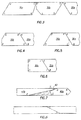
- Figure 3 shows instances where the members do not allow room for nesting if left in their original orientation, that is, with the top face of the member up and the leading end on the right.
- nesting is possible if the members are "flipped" such that the member is rotated about it longitudinal axis and the top face is placed downward.
- top angle C of member 30b is supplementary to the bottom angle B of member 30a
- member 30b can be flipped, or turned over, and the members 30a and 30b will nest, as seen in Figure 4. This will hold true for all supplementary angles. So the members can be reoriented to move all supplementary angles together.
- a member can be rotated 180 degrees about its lateral axis, or spun like a top, to match supplementary angles together. For example, if bottom angle F or member 30b is supplementary to top angle A or member 30a, then member 30b can be spun 180 degrees to the orientation in Figure 5, which allows for nesting.
- a member can be rotated about its longitudinal axis (flipped) and rotated about its lateral axis (spun) to place a supplementary angles adjacent.
- bottom angle B of member 30a is supplementary to bottom angle I of member 30c
- member 30c can be flipped and spun to the position shown in Figure 6 and the members nested together. All of these reorientations can be manipulated in the computer program to arrange the members to be cut in a more efficient manner.
- angles which sum to less than 180 degrees but are not adjacent with the members in their original orientation can be flipped, spun or both to achieve nesting.
- the nesting of these angles will still result in waste production (just as seen in waste portions 24 and 26) but will still reduce waste production.
- butt cuts can be taken into account.
- the butt cut 42 has an angle X of 90 degrees.
- the sum of top angle X and top angle D would be greater than 180 degrees and nesting would not be allowed.
- Butt cuts are typically short vertical cuts (90 degrees), although as used here, the term is intended to encompass more than simply 90 degree cuts.
- the computer program will compute whether a butt cut member will nest with an adjacent member and move these members together.
- the trailing member may need to be "moved back," or placed on the stock lumber with enough space to prevent damage to the trailing member when a separating cut is made between the two members.
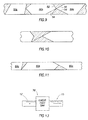
- Figure 9 presents members 50a, 50b and 50c, which cannot be nested together. Additionally, no cut can be made along cut lines 56 or 58 of the trailing end of member 50a without damaging member 50b (see dashed lines).
- One way to overcome this problem is to place the trailing member 50b far enough back on the stock to prevent any damage, as seen in Figure 10. However, this results in the waste of stock.
- a separating cut would be made along end cut 52 or 54 of trailing member 50b prior to any cut being made on the trailing end of member 50a.
- a cut would be made along leading end 52 of member 50b, the remaining stock (including the lumber which will make up members 50b and 50c) would be moved backwards out of the way of the saw head and then cuts would be made along the trailing end of member 50a along lines 56 and 58.
- Member 50a would be moved downstream out of the way and the stock would be positioned for a cut along line 54. This method greatly reduces the waste of stock and further optimizes the use of lumber in a linear feed saw.
- FIG. 12A and B show a flow chart of logic steps taken in arranging the truss members for cutting in a linear feed saw. Note that terms such as "arranging” and “orienting” presume a physical analog for the electronically stored truss member information.
- the truss member information has been stored in a list. Similarly, the available stock length has been stored as well.
- the program may be capable of handling more than one size stock, for example, it can match truss members to 8, 10 and 12 foot stock, and/or more than one grade of lumber, such as placing all truss members of one grade onto stock of the same grade.
- the program selects a first piece to be cut which may be referred to as the fixed piece.
- the fixed piece selected is the longest remaining piece to be created, however, other members may be selected instead.
- the remaining length of the unused stock is calculated and a second member of shorter length (such that it will fit onto the remaining stock) is selected and may be referred to as the movable piece.
- the member angles are compared to the angles of the trailing end of the first member as indicated. Where a supplementary angle is found, a "match," the members are moved together or nested.
- the movable piece is flipped, or rotated along its longitudinal axis, as discussed above and seen at Figure 4. Where the only supplementary angle is found at the opposite end of the movable piece, the movable piece is rotated around its lateral axis, or spun, as discussed above in relation to Figure 5. If still necessary, the movable piece is then flipped (having now been flipped and spun) as described above in relation to Figure 6.
- the program may try one or more of the remaining truss members to attempt to find a supplementary angle "match.” Alternately or afterwards, the program will go through the same logic searching for "close fits” trying to pair adjacent angles that sum to less than 180 degrees as discussed above. Preferably, the program will attempt to fit the "closest” fits first - that is, go through the possible nesting pieces and insert the piece which sums with the adjacent angle to closest to 180 degrees. Stated another way, the program may run through the list of remaining pieces and find the one that will nest with the least amount of waste between the adjacent angles. This is not mandatory.
- a truss member which cannot be nested may be placed on the stock to be cut.
- the truss member must either be placed with enough space to avoid damage to the following member (if any), as described in relation to Figure 10 above, or the program will indicate that a separating cut must be first made on the trailing member prior to cutting the end cuts on the leading member, as described above in relation to Figure 9.
- the program having arranged and oriented the plurality of truss members to optimize the use of lumber in the linear feed saw, the program results are used to feed stock into a linear feed saw apparatus 70 which cuts the truss members 10 from the stock 12, as seen in block diagram Figure 13.
Landscapes
- Business, Economics & Management (AREA)
- Engineering & Computer Science (AREA)
- Human Resources & Organizations (AREA)
- Economics (AREA)
- Strategic Management (AREA)
- Tourism & Hospitality (AREA)
- Theoretical Computer Science (AREA)
- General Physics & Mathematics (AREA)
- Marketing (AREA)
- General Business, Economics & Management (AREA)
- Physics & Mathematics (AREA)
- Game Theory and Decision Science (AREA)
- Quality & Reliability (AREA)
- Operations Research (AREA)
- Entrepreneurship & Innovation (AREA)
- Development Economics (AREA)
- Manufacturing & Machinery (AREA)
- Health & Medical Sciences (AREA)
- General Health & Medical Sciences (AREA)
- Primary Health Care (AREA)
Abstract
Description
- The present invention relates generally to a system and method for optimization of the cutting of lumber, and more particularly to a computer-based system and method for selecting and orienting truss members for cutting in a linear feed saw.
- With the rising cost of wood and lumber, it has become ever more important to reduce the lost costs associated with lumber waste produced in the truss manufacturing industry. Optimization of lumber use has been addressed in
U.S. Pat. No. 5,444,635 to Blaine, which is incorporated herein for all purposes. However, further optimization is still needed. The instant invention specifically addresses optimization of lumber use in a linear feed saw. The linear feed saw will not be explained in detail, however, examples of such saws can be found in U.S. Pat. Application Publication Nos.US 2004/0069106 to McAdoo andUS 2005/0076759 to Westfall, et al. , both of which are incorporated herein for all purposes. - A computer-based method for maximizing the use of lumber in the production of truss members for a truss assembly using a linear feed saw apparatus. The method comprises storing a list of truss members to be cut by the linear feed saw apparatus, selecting from the list a first truss member for cutting, the first member having a trailing end. A second truss member from the list is selected for cutting, the second member having a first end that will nest with the trailing end of the first member. The second member is oriented such that its first end nests with the trailing end of the first member. The members are then cut using the linear feed saw. The nesting members can abut across the entire member width, only across a portion of the member width or at a single point. The nested ends of the first and second members may be bevel cuts. The selecting of a second truss member may comprise comparing the angles of the cuts to be made on the trailing end of the first members to the cuts to be made on the ends of at least two of the members on the list. The selected member may have an angle to be cut which is supplementary to one of the angles of the trailing end of the first member or which is close fitting with an angle on the trailing end of the first member. The selected member is oriented such that the supplementary or close fitting angle of the selected member is adjacent the corresponding supplementary or close fitting angle of the first member. Orienting the selected member may further comprise rotating the member around its longitudinal axis, its lateral axis or both.
- Examples of the present invention will now be described in detail with reference to the accompanying drawings, in which:
- Figure 1 is a top view of a plurality of truss members to be cut from a single piece of stock lumber, the members nested with one another in accordance with the invention;
- Figure 2 is a top view of a plurality of truss members to be cut from a single piece of stock lumber, the truss members not nested with one another;
- Figure 3 is a top view of instances where the members do not allow room for nesting if left in their original orientation;
- Figure 4 is a top view of a truss member oriented by rotation about its longitudinal axis to provide for nesting;
- Figure 5 is a top view of a truss member oriented by rotation about its lateral axis to provide for nesting;
- Figure 6 is a top view of a truss member oriented by rotation about both its longitudinal and lateral axes to provide for nesting;
- Figure 7 is a top view of two truss members nested, one member having a butt cut end;
- Figure 8 is a top view of two truss members nested, both members having butt cut ends;
- Figure 9 is a top view of truss members arranged to optimize stock usage wherein a separation cut must be made to the trailing piece prior to cuts being made to the trailing end of the leading piece;
- Figure 10 is a top view of the spacing required if a separation cut is not made prior to cuts to the trailing end of the leading member;
- Figure 11 is a elevational view of nested bevel cuts;
- Figure 12A and B are flow charts of a computer program for optimization of lumber usage in a linear saw; and
- Figure 13 is a block diagram of a liner feed saw apparatus.
- The making and using of the presently preferred embodiments are discussed in detail below. It should be appreciated, however, that the present invention provides many applicable inventive concepts that can be embodied in a wide variety of specific contexts. The specific embodiments discussed are merely illustrative of specific ways to make and use the invention, and do not limit the scope of the invention.
- With reference now to Figure 1, there is shown a plurality of
truss members 10 to be cut from a single piece oflumber 12. Figure 1 is a top view of a piece of lumber, such as a two by four with lines indicating where cuts are to be made. The cut lines are shown as solid lines and the resultingwaste lumber 14 is shown as cross-hatched. Figure 1 shows the general concept of "nesting" the truss members to reduce waste. The truss members are laid out such thatmember 10a would be the first member cut as thelumber 12 is fed into the linear feed saw. That is, the right side of the lumber is fed first into the saw. - The
trailing end 16 of thefirst member 10a is coincident with the leadingend 18 of thesecond member 18. These two pieces are "nested" in that they linearly overlap - that is, the furthest extent of thetrailing end 16 ofmember 10a extends past the leadingend 18 of themember 10b as indicated by the dashed lines and distance N. In this type of nesting, the ends of the two nesting members abut one another across the entire width of the lumber. Nesting is not limited to this configuration, however. Nesting is defined as any linear overlap between adjacent truss members. All of the cuts shown in Figure 1 are nesting cuts and all of the members nest with their adjacent members except for thecut 30.Members - Another type of nesting is seen with
members end 22 ofmember 10c has two cuts and produceswaste section 14.Members lumber 12.Members Waste section 24 is produced when these members are cut. Similarly,members waste sections - Each
truss member 10 has four cut angles with respect to the edge of the lumber. The angles formember 10a are labeled A-B, the angles formember 10b are labeled C-F, etc. The truss members, as shown, are all "right side up." That is, the top faces of the members, which will face upward when the truss members are assembled on a truss assembly table, are face up in the Figure. (Truss assembly apparatus are known in the art and are described in detail, for example, inU.S. Pat. No. 4,943,038 to Harnden , which is incorporated herein by reference for all purposes.) Also note that the cuts in Figure 1 are all vertical cuts. That is, they are perpendicular to the plane of the member faces. The angles at the upper edge of the lumber will be referred to herein as "top angles," such as angles A, C, F, G, J, etc. They will be referred to as "top angles" even where the truss member has been flipped, or rotated about its longitudinal axis, such that the top face of the member is facing downward. Similarly, the "bottom angles" are at the lower edge of the lumber, such as angles B, D, E, H, I, etc., and will be referred to as "bottom angles" even when the truss member has been flipped over. - Top angles A and C are supplementary angles, hence, the ends 16 and 18 coincide. The same is true of bottom angles B and D. Similarly, top angles J and K are supplementary angles, resulting in the coincidence of at least a portion of member ends 20 and 22. Bottom angles M and P are not supplementary, however, their sum is less than 180 degrees and so the bottom angles of
members members members - Figure 3 shows instances where the members do not allow room for nesting if left in their original orientation, that is, with the top face of the member up and the leading end on the right. However, nesting is possible if the members are "flipped" such that the member is rotated about it longitudinal axis and the top face is placed downward. For example, if top angle C of
member 30b is supplementary to the bottom angle B ofmember 30a, thenmember 30b can be flipped, or turned over, and themembers - In a similar manner, a member can be rotated 180 degrees about its lateral axis, or spun like a top, to match supplementary angles together. For example, if bottom angle F or
member 30b is supplementary to top angle A ormember 30a, thenmember 30b can be spun 180 degrees to the orientation in Figure 5, which allows for nesting. - Finally, a member can be rotated about its longitudinal axis (flipped) and rotated about its lateral axis (spun) to place a supplementary angles adjacent. For example, if, in Figure 3, bottom angle B of
member 30a is supplementary to bottom angle I ofmember 30c, thenmember 30c can be flipped and spun to the position shown in Figure 6 and the members nested together. All of these reorientations can be manipulated in the computer program to arrange the members to be cut in a more efficient manner. - Similarly, angles which sum to less than 180 degrees but are not adjacent with the members in their original orientation can be flipped, spun or both to achieve nesting. The nesting of these angles will still result in waste production (just as seen in
waste portions 24 and 26) but will still reduce waste production. - As another method of reducing waste and optimizing lumber use, "butt cuts" can be taken into account. In Figure 7, for example, the butt cut 42 has an angle X of 90 degrees. Following the rules above, the sum of top angle X and top angle D would be greater than 180 degrees and nesting would not be allowed. However, recognizing that butt cut 42 results in an end cut short enough to allow nesting results in further optimization. Butt cuts are typically short vertical cuts (90 degrees), although as used here, the term is intended to encompass more than simply 90 degree cuts. A similar result is seen in Figure 8. The computer program will compute whether a butt cut member will nest with an adjacent member and move these members together.
- Throughout the discussion above the analyzing of whether members will nest has been discussed in terms of supplementary angles and summing of angles to a benchmark of 180 degrees. This is simply one method of calculation and the examples are not intended to be limiting. For example, the program could compare a member angle to the "open space" angle adjacent another member and achieve the same result. It is not intended that a user can avoid infringement simply by changing which angles (angles of wood or angles of free space) are measured, whether the mathematical algorithm is rearranged using simple algebraic and geometric rules (for example, finding the difference between angles rather than the sums), or by using some other benchmark (for example, measuring all angles against the vertical) to reach the same conclusions.
- If no nesting is possible, neither supplementary angles for exact matches nor angle summing to less than 180 degrees for imperfect matches exist, then the trailing member may need to be "moved back," or placed on the stock lumber with enough space to prevent damage to the trailing member when a separating cut is made between the two members.
- Figure 9 presents
members cut lines member 50b (see dashed lines). One way to overcome this problem is to place the trailingmember 50b far enough back on the stock to prevent any damage, as seen in Figure 10. However, this results in the waste of stock. - The present invention presents a solution. In Figure 9, a separating cut would be made along end cut 52 or 54 of trailing
member 50b prior to any cut being made on the trailing end of member 50a. A cut would be made along leadingend 52 ofmember 50b, the remaining stock (including the lumber which will make upmembers lines line 54. This method greatly reduces the waste of stock and further optimizes the use of lumber in a linear feed saw. - The above discussion has centered around nesting "regular" cuts. That is, the cuts are made vertically, at a right angle to the top face of the member. The same optimization can be employed with bevel cuts as well. In Figure 11, is a side elevational view of
truss members - In practice, the above steps are taken in a software program stored on a digital media. The software or a computer-based system is used to store a list of truss members to be cut and a list of stock members available for creating the truss members. The list of truss members to be cut must include all of the dimensional data needed to describe the truss members, including the length and various angles of the members. Figures 12A and B show a flow chart of logic steps taken in arranging the truss members for cutting in a linear feed saw. Note that terms such as "arranging" and "orienting" presume a physical analog for the electronically stored truss member information.
- At the top of the flow chart, the truss member information has been stored in a list. Similarly, the available stock length has been stored as well. The program may be capable of handling more than one size stock, for example, it can match truss members to 8, 10 and 12 foot stock, and/or more than one grade of lumber, such as placing all truss members of one grade onto stock of the same grade.
- The program selects a first piece to be cut which may be referred to as the fixed piece. Typically the fixed piece selected is the longest remaining piece to be created, however, other members may be selected instead. The remaining length of the unused stock is calculated and a second member of shorter length (such that it will fit onto the remaining stock) is selected and may be referred to as the movable piece. For the selected movable piece, the member angles are compared to the angles of the trailing end of the first member as indicated. Where a supplementary angle is found, a "match," the members are moved together or nested. If a supplementary angle is found at a top angle for an adjacent bottom angle (or vice versa), the movable piece is flipped, or rotated along its longitudinal axis, as discussed above and seen at Figure 4. Where the only supplementary angle is found at the opposite end of the movable piece, the movable piece is rotated around its lateral axis, or spun, as discussed above in relation to Figure 5. If still necessary, the movable piece is then flipped (having now been flipped and spun) as described above in relation to Figure 6.
- If no supplementary angles are found on the selected second piece, the program may try one or more of the remaining truss members to attempt to find a supplementary angle "match." Alternately or afterwards, the program will go through the same logic searching for "close fits" trying to pair adjacent angles that sum to less than 180 degrees as discussed above. Preferably, the program will attempt to fit the "closest" fits first - that is, go through the possible nesting pieces and insert the piece which sums with the adjacent angle to closest to 180 degrees. Stated another way, the program may run through the list of remaining pieces and find the one that will nest with the least amount of waste between the adjacent angles. This is not mandatory.
- Preferably, when the exact matches (supplementary angles) and close fits (nesting of angles summing to less than 180 degrees) are exhausted, a truss member which cannot be nested may be placed on the stock to be cut. In this case, the truss member must either be placed with enough space to avoid damage to the following member (if any), as described in relation to Figure 10 above, or the program will indicate that a separating cut must be first made on the trailing member prior to cutting the end cuts on the leading member, as described above in relation to Figure 9.
- Once a piece of stock is "full," that is, there is not enough stock to handle another truss member, the remaining stock (if any) is waste and the routine is run again for the next piece of stock.
- It is not intended that these logical steps must be followed in exactly the order presented here, or even that all of the steps be followed. For example, the routine need not necessarily compare every remaining truss member in search of a supplementary angle or a closer fit. Similarly, the order of flipping and rotating the members can be done in another order. Other deviations from the logic tree will be readily apparent to those of skill in the art. Details like these may be sacrificed without departing from the spirit of the invention.
- Finally, the program having arranged and oriented the plurality of truss members to optimize the use of lumber in the linear feed saw, the program results are used to feed stock into a linear feed saw
apparatus 70 which cuts thetruss members 10 from thestock 12, as seen in block diagram Figure 13.
Claims (14)
- A computer-based method for maximizing the use of lumber in the production of a plurality of truss members for a truss assembly using a linear feed saw apparatus, the method comprising the steps of:storing a list of a plurality of truss members to be cut by the linear feed saw apparatus;selecting from the list a first truss member for cutting, the first member having a leading end and a trailing end, the leading end for feeding into the linear feed saw first;selecting from the list a second truss member for cutting, the second member having a first end that will nest with the trailing end of the first member;orienting the second truss member such that its first end nests with the trailing end of the first member; andcutting the truss members using the linear feed saw.
- A method as in Claim 1, wherein the first end of the second member abuts the trailing end of the first member across the entire member width.
- A method as in Claim 1, wherein the first end of the second member abuts the trailing end of the first member across only a portion of the member width.
- A method as in Claim 1, wherein the first end of the second member abuts the trailing end of the first member only at a single point.
- A method as in Claim 1, wherein the nested ends of the first and second members are bevel cuts.
- A method as in Claim 1 wherein the step of selecting a second truss member further comprises comparing the angles of the cuts to be made on the trailing end of the first member to the angles of the cuts to be made on the ends of at least two of the members on the list.
- A method as in Claim 6, further comprising selecting a member from the list having an angle to be cut which is supplementary to one of the angles of the trailing end of the first member.
- A method as in Claim 7, further comprising orienting the selected member such that the supplementary angle of the selected member is adjacent the corresponding complimentary angle of the first member.
- A method as in Claim 8, wherein the step of orienting further comprises rotating the member around its longitudinal axis.
- A method as in Claim 8, wherein the step of orienting further comprises rotating the selected member about its latitudinal axis.
- A method as in Claim 10, wherein the step of orienting further comprises rotating the member around its longitudinal axis.
- A method as in Claim 6, further comprising selecting a member from the list having a close angle which sums with a corresponding angle of the trailing end of the first member to less than 180 degrees.
- A method as in Claim 12, further comprising orienting the selected member such that the close angle of the selected member is adjacent the corresponding angle of the trailing end of the first member and nests with the first member.
- A method as in Claim 13, wherein the step of orienting further comprises rotating the member around its longitudinal axis.
Applications Claiming Priority (1)
| Application Number | Priority Date | Filing Date | Title |
|---|---|---|---|
| US11/249,658 US7647133B2 (en) | 2005-10-12 | 2005-10-12 | Method and apparatus for optimization of cutting lumber |
Publications (1)
| Publication Number | Publication Date |
|---|---|
| EP1777652A1 true EP1777652A1 (en) | 2007-04-25 |
Family
ID=37488040
Family Applications (1)
| Application Number | Title | Priority Date | Filing Date |
|---|---|---|---|
| EP20060121510 Withdrawn EP1777652A1 (en) | 2005-10-12 | 2006-09-29 | Method and apparatus for optimization of cutting lumber |
Country Status (4)
| Country | Link |
|---|---|
| US (1) | US7647133B2 (en) |
| EP (1) | EP1777652A1 (en) |
| AU (1) | AU2006213961B2 (en) |
| CA (1) | CA2562603C (en) |
Cited By (1)
| Publication number | Priority date | Publication date | Assignee | Title |
|---|---|---|---|---|
| AU2024278305B2 (en) * | 2023-06-20 | 2025-08-28 | Mitek Holdings, Inc. | Automated truss manufacturing and assembly system |
Families Citing this family (1)
| Publication number | Priority date | Publication date | Assignee | Title |
|---|---|---|---|---|
| US8010216B2 (en) * | 2006-05-18 | 2011-08-30 | Roise Geoffrey J | System and method for cutting-stock optimization across schedules and batches |
Citations (2)
| Publication number | Priority date | Publication date | Assignee | Title |
|---|---|---|---|---|
| US5444635A (en) * | 1993-09-08 | 1995-08-22 | Alpine Engineered Products, Inc. | Optimizing technique for sawing lumber |
| US20020092389A1 (en) * | 2001-03-16 | 2002-07-18 | Feldman Vitaly J. | Critical area preprocessing of numeric control data for cutting sheet material |
Family Cites Families (50)
| Publication number | Priority date | Publication date | Assignee | Title |
|---|---|---|---|---|
| US3289662A (en) | 1964-02-04 | 1966-12-06 | Swenson Granite Co Inc John | Dual head sawing machine |
| US3910142A (en) | 1971-02-05 | 1975-10-07 | Automated Building Components | Automated saw |
| US3848646A (en) | 1971-12-30 | 1974-11-19 | Hines E Lumber Co | Method and apparatus for cutting lumber to random or specified clear lengths |
| US3884646A (en) * | 1972-12-05 | 1975-05-20 | James T Kenney | Structural panel and method of fabrication thereof |
| GB1426348A (en) * | 1973-11-12 | 1976-02-25 | Yokoyama Tekko Kk | Automatic lumbering apparatus |
| US4017976A (en) | 1974-07-03 | 1977-04-19 | Barr Anthony J | Apparatus and method for maximum utilization of elongated stock |
| US4195346A (en) | 1976-03-25 | 1980-03-25 | Schroder Staffan H | Method and apparatus for sorting and classifying timber |
| US4239069A (en) * | 1979-08-10 | 1980-12-16 | Zimmerman Edwin H | Automatic cant production machine |
| US4316400A (en) | 1980-01-16 | 1982-02-23 | Stoddard H. Pyle | Wood member cutting apparatus |
| US4277998A (en) | 1980-01-16 | 1981-07-14 | Stoddard H. Pyle | Wood member cutting apparatus |
| US4461196A (en) | 1982-09-29 | 1984-07-24 | Schramm Ii William M | Mitre box system for cutting compound angles |
| JPS6044298A (en) * | 1983-08-22 | 1985-03-09 | 光洋自動機株式会社 | Manufacture of punching label, etc. |
| US4574670A (en) | 1983-11-17 | 1986-03-11 | Lockheed Corporation | Multiple angle cutting apparatus |
| US4545274A (en) | 1984-08-01 | 1985-10-08 | Speed Cut, Inc. | Hip, valley and jack rafter cutting apparatus |
| US4676129A (en) | 1984-10-02 | 1987-06-30 | Gang-Nail Systems, Inc. | Automated truss component saw apparatus |
| US4576076A (en) | 1984-10-16 | 1986-03-18 | Speed Cut, Inc. | Multiple intersecting planes cutting device |
| US4641557A (en) | 1984-12-26 | 1987-02-10 | Emerson Electric Co. | Electronically controlled power saw |
| US4840207A (en) * | 1985-08-09 | 1989-06-20 | Mitek Industries, Inc. | Apparatus for making wooden I-beams |
| US4794963A (en) | 1987-10-05 | 1989-01-03 | Nemschoff Chairs, Inc. | Method and apparatus for optimizing the cutting of raw boards into product boards |
| AT393983B (en) * | 1988-10-04 | 1992-01-10 | Gfm Holding Ag | CUTTING MACHINE FOR CUTTING OUT CUTS FROM TAPE-BASED STARTING MATERIAL, IN PARTICULAR PREPREGS COVERED ON ONE OR ON SIDE |
| US4943038A (en) | 1989-07-17 | 1990-07-24 | Alpine Engineered Products, Inc. | Truss assembly apparatus |
| FI90454C (en) | 1990-02-22 | 1994-02-10 | Patenttitoimisto T Poutanen Oy | Method of making a nail plate chair |
| US6899005B1 (en) | 1991-10-09 | 2005-05-31 | Black & Decker Inc. | Adjustable fence for compound miter saw |
| US5297463A (en) | 1991-10-09 | 1994-03-29 | Black & Decker Inc. | Adjustable fence for compound miter saw |
| US5176060A (en) | 1991-11-18 | 1993-01-05 | Thornton Jack L | Truss miter angle saws |
| US6212983B1 (en) | 1992-03-04 | 2001-04-10 | Stoddard H. Pyle | Tiltable infeed and outfeed saw table |
| US5943239A (en) | 1995-03-22 | 1999-08-24 | Alpine Engineered Products, Inc. | Methods and apparatus for orienting power saws in a sawing system |
| US5662019A (en) | 1995-05-03 | 1997-09-02 | Denman; Paul M. | Safety device for woodworking tools |
| DE29507871U1 (en) | 1995-05-12 | 1995-07-27 | Hermann Pfauter GmbH & Co., 71636 Ludwigsburg | Hobbing machine |
| US5931073A (en) | 1995-08-28 | 1999-08-03 | Hoyer-Ellefsen; Sigurd | Bevel angle control on translatory saw apparatus |
| DE19619720A1 (en) | 1996-05-15 | 1997-11-20 | Index Werke Kg Hahn & Tessky | Multi-spindle lathe |
| US6116126A (en) | 1996-07-10 | 2000-09-12 | Van Den Bulcke; Marc | Method and machine for making profile pieces |
| AU7688498A (en) * | 1997-05-19 | 1998-12-11 | Stephen S. Daniell | Powered cutting saw system and method for joining materials |
| US6260263B1 (en) | 1997-10-06 | 2001-07-17 | Mitek Holdings, Inc. | Truss table with flipper |
| DE59914164D1 (en) | 1998-09-25 | 2007-03-15 | Hans Hundegger | Woodworking equipment |
| US6615100B1 (en) | 1999-07-27 | 2003-09-02 | James Francis Urmson | Automated roof truss component saw |
| US6263773B1 (en) | 1999-09-16 | 2001-07-24 | Mcadoo David L. | Engineered wood products cutting method and apparatus |
| US6539830B1 (en) | 1999-10-13 | 2003-04-01 | The Koskovich Company | Automated board processing apparatus |
| US6272961B1 (en) | 2000-02-07 | 2001-08-14 | Wy Peron Lee | Cutting machine with built-in miter cutting feature |
| US6705190B2 (en) * | 2000-07-24 | 2004-03-16 | Coe Newnes Mcgehee Ulc | Lumber trimmer |
| US6886251B1 (en) * | 2001-01-31 | 2005-05-03 | Vp Buildings, Inc. | Beam fabrication system |
| ES2294062T3 (en) | 2001-05-17 | 2008-04-01 | CHIRON-WERKE GMBH & CO. KG | MACHINE TOOL AND PROCEDURE FOR MECHANIZATION OF A PART TO BE PREPARED IN THE FORM OF A BAR. |
| US6640855B2 (en) | 2001-09-05 | 2003-11-04 | Hearthstone, Inc. | Log home fabrication process and associate log cutting machine |
| US6941864B2 (en) | 2002-08-20 | 2005-09-13 | Precision Automation, Inc. | Method to control optimized cutting of stock to satisfy a cut list |
| US20050076759A1 (en) | 2003-10-08 | 2005-04-14 | Brian Westfall | Linear saw with stab-cut bevel capability |
| US20040069106A1 (en) | 2002-10-14 | 2004-04-15 | Mcadoo David L. | Linear feed cutting apparatus and method |
| US6690990B1 (en) * | 2002-12-02 | 2004-02-10 | CENTRE DE RECHERCHE INDUSTRIELLE DU QUéBEC | Method of optimizing a layout of selected parts to be cut |
| DE10316910B3 (en) * | 2003-04-12 | 2004-09-02 | Sms Meer Gmbh | Production of metallic pipes comprises rolling the start of the pipe loop and/or the end of the pipe loop together using an inner tool |
| US20050262977A1 (en) * | 2004-05-25 | 2005-12-01 | Wilkerson Steven J | Machine and process for optimizing truss cutting |
| US7870879B2 (en) * | 2005-06-28 | 2011-01-18 | Mitek Holdings, Inc. | Automated system for precision cutting crooked lumber |
-
2005
- 2005-10-12 US US11/249,658 patent/US7647133B2/en active Active
-
2006
- 2006-09-13 AU AU2006213961A patent/AU2006213961B2/en active Active
- 2006-09-29 EP EP20060121510 patent/EP1777652A1/en not_active Withdrawn
- 2006-10-05 CA CA2562603A patent/CA2562603C/en active Active
Patent Citations (2)
| Publication number | Priority date | Publication date | Assignee | Title |
|---|---|---|---|---|
| US5444635A (en) * | 1993-09-08 | 1995-08-22 | Alpine Engineered Products, Inc. | Optimizing technique for sawing lumber |
| US20020092389A1 (en) * | 2001-03-16 | 2002-07-18 | Feldman Vitaly J. | Critical area preprocessing of numeric control data for cutting sheet material |
Non-Patent Citations (3)
| Title |
|---|
| ANONYMOUS, INTERNET CITATION, Internet, XP002411347, Retrieved from the Internet <URL:http://www.alpeng.com/GoodConnectionsTM.html> [retrieved on 20061212] * |
| DAVID MCADOO: "The Awesome Power of Optimizing with The Alpine Linear Saw (ALS)", GOOD CONNECTION SPRING 2005, 16 May 2005 (2005-05-16), Online, XP002411346, Retrieved from the Internet <URL:http://www.alpeng.com/upload/19373/ALSstories_SHAN-WEB.pdf> [retrieved on 20061212] * |
| HAN G C ET AL: "TWO-STAGE APPROACH FOR NESTING IN TWO-DIMENSIONAL CUTTING PROBLEMS USING NEURAL NETWORK AND SIMULATED ANNEALING", INSTITUTION OF MECHANICAL ENGINEERS. PROCEEDINGS. JOURNAL OF ENGINEERING MANUFACTURE, MECHANICAL ENGINEERING PUBLICATIONS LTD. LONDON, GB, vol. 210, no. B06, January 1996 (1996-01-01), pages 509 - 519, XP000646321, ISSN: 0954-4054 * |
Cited By (1)
| Publication number | Priority date | Publication date | Assignee | Title |
|---|---|---|---|---|
| AU2024278305B2 (en) * | 2023-06-20 | 2025-08-28 | Mitek Holdings, Inc. | Automated truss manufacturing and assembly system |
Also Published As
| Publication number | Publication date |
|---|---|
| CA2562603A1 (en) | 2007-04-12 |
| US7647133B2 (en) | 2010-01-12 |
| AU2006213961B2 (en) | 2009-05-14 |
| US20070113929A1 (en) | 2007-05-24 |
| AU2006213961A1 (en) | 2007-04-26 |
| CA2562603C (en) | 2016-04-05 |
Similar Documents
| Publication | Publication Date | Title |
|---|---|---|
| CA2379817C (en) | Method and system for organizing data | |
| US9505072B2 (en) | Systems and methods for auditing optimizers tracking lumber in a sawmill | |
| Bolton | Biarc curves | |
| AU783340B2 (en) | Automated board processing apparatus | |
| CA2497621A1 (en) | Method of generating a computer readable model | |
| US20140238546A1 (en) | Systems and methods of orienting a cant in lumber mills | |
| US20230415241A1 (en) | Handle apparatus for an industrial machine tool | |
| CN100421850C (en) | Insert for a finger milling cutter | |
| CA2562603C (en) | Method and apparatus for optimization of cutting lumber | |
| US7853349B2 (en) | Systems and methods for gangsaw management | |
| CN111247493A (en) | Method and machine tool for machining a workpiece | |
| CN113111458A (en) | DXF-based sheet metal part automatic identification and positioning method | |
| US20140251499A1 (en) | Methods and systems of managing chipping and sawing equipment | |
| CN118080342A (en) | Device and method for separating stems and tobacco scraps and recovering tobacco in cigarette making process | |
| US20050262977A1 (en) | Machine and process for optimizing truss cutting | |
| US10894332B2 (en) | Systems and methods for minimizing a total number of cuts to separate media instances imaged onto a media sheet | |
| US9895756B2 (en) | Flip-down table-saw fence | |
| Lewis | Sawmill simulation and the best opening face system: A users guide | |
| CN104199384B (en) | A kind of casing boss Profile milling machining locus rapid generation of feature based | |
| SE542289C2 (en) | System and method for selecting a tool assembly | |
| US20190160552A1 (en) | Method for determining raw material shape, processing method, system for determining raw material shape, and program for determining raw material shape | |
| Bouaziz et al. | Optimization and selection of cutters for 3D pocket machining | |
| AU2006202071B2 (en) | An apparatus and method for producing barrel staves | |
| US20200164456A1 (en) | Method and system for preparing machining and/or cutting of a bar material | |
| EP2439030A1 (en) | Method and apparatus for machining and dividing a cant into pieces of timber |
Legal Events
| Date | Code | Title | Description |
|---|---|---|---|
| PUAI | Public reference made under article 153(3) epc to a published international application that has entered the european phase |
Free format text: ORIGINAL CODE: 0009012 |
|
| AK | Designated contracting states |
Kind code of ref document: A1 Designated state(s): AT BE BG CH CY CZ DE DK EE ES FI FR GB GR HU IE IS IT LI LT LU LV MC NL PL PT RO SE SI SK TR |
|
| AX | Request for extension of the european patent |
Extension state: AL BA HR MK YU |
|
| 17P | Request for examination filed |
Effective date: 20071015 |
|
| AKX | Designation fees paid |
Designated state(s): AT BE BG CH CY CZ DE DK EE ES FI FR GB GR HU IE IS IT LI LT LU LV MC NL PL PT RO SE SI SK TR |
|
| 17Q | First examination report despatched |
Effective date: 20071126 |
|
| STAA | Information on the status of an ep patent application or granted ep patent |
Free format text: STATUS: THE APPLICATION IS DEEMED TO BE WITHDRAWN |
|
| 18D | Application deemed to be withdrawn |
Effective date: 20130719 |