EP1777489A1 - Method and apparatus for inspecting an object - Google Patents
Method and apparatus for inspecting an object Download PDFInfo
- Publication number
- EP1777489A1 EP1777489A1 EP06255431A EP06255431A EP1777489A1 EP 1777489 A1 EP1777489 A1 EP 1777489A1 EP 06255431 A EP06255431 A EP 06255431A EP 06255431 A EP06255431 A EP 06255431A EP 1777489 A1 EP1777489 A1 EP 1777489A1
- Authority
- EP
- European Patent Office
- Prior art keywords
- structured light
- light
- light source
- imaging sensor
- structured
- Prior art date
- Legal status (The legal status is an assumption and is not a legal conclusion. Google has not performed a legal analysis and makes no representation as to the accuracy of the status listed.)
- Granted
Links
- 238000000034 method Methods 0.000 title claims abstract description 28
- 230000010287 polarization Effects 0.000 claims abstract description 38
- 238000003384 imaging method Methods 0.000 claims abstract description 31
- 238000005259 measurement Methods 0.000 claims abstract description 24
- 239000004973 liquid crystal related substance Substances 0.000 claims description 4
- XUIMIQQOPSSXEZ-UHFFFAOYSA-N Silicon Chemical compound [Si] XUIMIQQOPSSXEZ-UHFFFAOYSA-N 0.000 claims description 2
- 229910052710 silicon Inorganic materials 0.000 claims description 2
- 239000010703 silicon Substances 0.000 claims description 2
- 238000012360 testing method Methods 0.000 description 8
- 239000000463 material Substances 0.000 description 5
- 238000010586 diagram Methods 0.000 description 4
- 230000007547 defect Effects 0.000 description 3
- 238000012545 processing Methods 0.000 description 3
- 238000005286 illumination Methods 0.000 description 2
- 238000007689 inspection Methods 0.000 description 2
- 238000000429 assembly Methods 0.000 description 1
- 230000000712 assembly Effects 0.000 description 1
- 239000003086 colorant Substances 0.000 description 1
- 230000002596 correlated effect Effects 0.000 description 1
- 230000000694 effects Effects 0.000 description 1
- 238000012986 modification Methods 0.000 description 1
- 230000004048 modification Effects 0.000 description 1
- 230000008646 thermal stress Effects 0.000 description 1
Images



Classifications
-
- G—PHYSICS
- G01—MEASURING; TESTING
- G01B—MEASURING LENGTH, THICKNESS OR SIMILAR LINEAR DIMENSIONS; MEASURING ANGLES; MEASURING AREAS; MEASURING IRREGULARITIES OF SURFACES OR CONTOURS
- G01B11/00—Measuring arrangements characterised by the use of optical techniques
- G01B11/24—Measuring arrangements characterised by the use of optical techniques for measuring contours or curvatures
- G01B11/25—Measuring arrangements characterised by the use of optical techniques for measuring contours or curvatures by projecting a pattern, e.g. one or more lines, moiré fringes on the object
- G01B11/2509—Color coding
Definitions
- This application relates generally to inspecting objects, and more specifically to methods and apparatus for inspecting objects using a light measurement system.
- Objects are sometimes inspected, for example, to determine a size and/or shape of all or a portion of the object and/or to detect defects in the object.
- some gas turbine engine components such as turbine or compressor blades, are inspected to detect fatigue cracks that may be caused by vibratory, mechanical, and/or thermal stresses induced to the engine.
- some gas turbine engine blades are inspected for deformations such as platform orientation, contour cross-section, bow and twist along a stacking axis, thickness, and/or chord length at given cross-sections.
- deformations such as platform orientation, contour cross-section, bow and twist along a stacking axis, thickness, and/or chord length at given cross-sections.
- continued operation of the object with one or more defects may reduce performance of the object and/or lead to object failures, for example, as cracks propagate through the object. Accordingly; detecting defects of the object as early as possible may facilitate increasing the performance of the object and/or reducing object failures.
- At least some objects are inspected using a light measurement system that projects a structured light pattern onto a surface of the object.
- the light measurement system images the structured light pattern reflected from the surface of the object and then analyzes the deformation of the reflected light pattern to calculate the surface features of the object.
- the object to be inspected is typically coupled to a test fixture and positioned proximate to the light measurement system.
- a light source is then activated such that emitted light illuminates the object to be inspected.
- a resultant image of the object may include noise caused by multiple bounce reflections of the emitted light. Such noise may result in reduced image quality and poor measurement results, possibly leading to an incorrect interpretation of surface features of the object.
- multiple bounce reflections may be caused by inter-reflections between the object and portions of the test fixture illuminated by the light source. For example, multiple bounce reflections may be caused if the test fixture has a shape or finish that casts reflections on the object, and/or if the object has a relatively mirror-like finish that reflects an image of the test fixture.
- crossed polarized filters may require multiple images to be taken of the object to reduce or eliminate multiple bounce reflections because reducing or eliminating such reflections may require different orientations of the filters.
- multiple images may also be required to analyze slope, texture, material, and/or other features of the object because analyzing differently angled reflections may require different orientations of the filters.
- a method for inspecting an object using a structured light measurement system that includes a light source and an imaging sensor.
- the method includes emitting light from the light source, polarizing each of a plurality of different wavelengths of the light emitted from the light source at different polarization angles, projecting light emitted from the light source onto a surface of an object, receiving light reflected from the object surface with the imaging sensor, and analyzing the light received by the imaging sensor to facilitate inspecting at least a portion of the object.
- a method for inspecting an object using a light measurement system that includes a light source and an imaging sensor.
- the method includes emitting light from the light source, polarizing a first wavelength of light emitted from the light source at a first polarization angle, polarizing a second wavelength of light emitted from the light source at a second polarization angle that is rotated from the first polarization angle, wherein the first and second wavelengths are different, projecting light emitted from the light source onto a surface of an object, receiving light reflected from the object surface using the imaging sensor, creating an image of light reflected from the object and received by the imaging sensor, and using the image to analyze a change of at least one of the first and second polarization angles after the light has been reflected from the object.
- a structured light measurement system for inspecting an object includes a structured light source configured to project structured light onto a surface of the object, a first polarizing filter configured to polarize a first wavelength of structured light emitted by the structured light source at a first polarization angle, a second polarizing filter configured to polarize a second wavelength of structured light emitted by the structured light source at a second polarization angle different from the first polarization angle, wherein the first and second wavelengths are different, and an imaging sensor configured to receive structured light reflected from the object surface.
- Figure 1 is a block diagram of an exemplary embodiment of a structured light measurement system 10 that is used to measure a plurality of surface features of an object 12.
- system 10 may be used to inspect and determine surfaces of object 12, wherein the surfaces may include features such as tilts, bends, twists, and/or warps when compared to a model representative of object 12.
- object 12 is a rotor blade, such as, but not limited to, a compressor or a turbine blade utilized in a turbine engine. Accordingly, and in the exemplary embodiment, object 12 includes an airfoil 14 extending outwardly from a platform 16. While the following description is directed to inspecting gas turbine engine blades, one skilled in the art will appreciate that inspection system 10 may be utilized to improve structured light imaging for any object.
- System 10 also includes a structured light source 22, such as, but not limited to, a white light lamp, a light emitting diode (LED), a laser, a liquid crystal display (LCD) device, a liquid crystal on silicon (LCOS) device, and/or a digital micromirror device (DMD) device.
- System 10 also includes one or more imaging sensors 24 that receive structured light reflected from object 12.
- imaging sensor 24 is a camera that receives and creates images using structured light reflected from object 12, although other imaging sensors 24 may be used.
- One or more computers 26 process images received from sensors 24, and a monitor 28 may be utilized to display information to an operator.
- Computer(s) 26 are programmed to perform functions described herein, and as used herein, the term computer is not limited to just those integrated circuits referred to in the art as computers, but broadly refers to computers, processors, microcontrollers, microcomputers, programmable logic controllers, application specific integrated circuits, and other programmable circuits, and these terms are used interchangeably herein.
- Figure 2 is a side sectional view of object 12.
- an object to be inspected for example object 12
- object 12 is coupled to a test fixture (not shown) and positioned proximate to system 10.
- object 12 is orientated relative to light source 22 (shown in Figure 1) with an angle d of orientation that enables a view to be presented to imaging sensors 24 (shown in Figure 1) such that a plane ⁇ defined by light source 22 and imaging sensors 24 substantially bisects one or more prismatic features of object 12.
- light source 22 shown in Figure 1
- imaging sensors 24 shown in Figure 1
- airfoil 14 and platform 16 each define a prismatic feature of object 12.
- Light source 22 is then activated causing emitted light to illuminate object 12.
- Imaging sensors 24 obtain an image of the emitted light pattern projected onto object 12.
- a resultant image of object 12 may include noise caused by multiple bounce reflections of the emitted light.
- Such noise may result in a reduced image quality and poor measurement results, possibly leading to an incorrect interpretation of surface features of object 12.
- light reflected off of prismatic surfaces (e.g., intersecting surfaces of airfoil 14 and platform 16) of object 12 may cause multiple bounce reflections, as illustrated in Figure 2.
- Directly reflected light paths, sometimes referred to as single bounce reflections, are indicated as SB in Figure 2
- multiple bounce reflections are indicated as MB in Figure 2.
- multiple bounce reflections MB may be caused by inter-reflections between object 12 and portions of the test fixture illuminated by light source 22.
- multiple bounce reflections MB may be created if the test fixture has a shape or finish that casts reflections on object 12, and/or if object 12 has a relatively mirror-like finish that reflects an image of the test fixture.
- system 20 includes two or more polarizing filters 30 for polarizing different wavelengths, or colors, of the light emitted from light source 22 at different polarization angles. More specifically, each polarizing filter 30 polarizes a particular wavelength of light emitted from light source 22 at a different polarization angle from other wavelengths. As polarized light reflects off object 12, the polarization angle of each wavelength changes. The change in the polarization angle of each wavelength can then be analyzed to determine multiple bounce reflections MB and/or features of object 12 such as, but not limited to, surface texture, surface orientation, and/or a material used in fabricating object 12.
- a change in a ratio defined between the polarization angles of different wavelengths is analyzed to determine multiple bounce reflections and/or features of object 12.
- multiple polarization states can be analyzed using only a single image of light reflected from object 12 and received by imaging sensor 24. Accordingly, multiple bounce reflections MB and/or features of object 12 can be determined using a single image of light received by imaging sensor 24, rather than using multiple images taken a different polarization illuminations.
- Polarizing filters 30 may be configured to polarize any wavelength of light emitted by light source 22 at any polarization angle. In some embodiments, and as shown in Figure 1, polarizing filters 30 are positioned at least partially between light source 22 and object 12 for polarizing light emitted by light source 22 before it is reflected from object 12. Although two polarizing filters 30 are illustrated in Figure 1, system 10 may include any number of polarizing filters 30 used to polarize any number of different wavelengths of light at different polarization angles.
- suitable color filters (not shown in Figure 1), such as, but not limited to, dichroic mirrors, may be positioned at least partially between light source 22 and polarization filters 30 for separating two or more wavelengths of light for polarization thereof. Additionally or alternatively, suitable color filters (not shown in Figure 1), such as, but not limited to, dichroic mirrors, may be positioned at least partially between object 12 and imaging sensor 24 for separating two or more wavelengths of light for reception by imaging sensor 24.
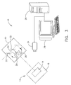
- Figure 3 is a block diagram of another exemplary embodiment of structured light measurement system 10 wherein light source 22 includes polarizing filters 30. Although three polarizing filters 30 are illustrated in Figure 3, light source 22 may include any number of polarizing filters 30 for polarizing any number of different wavelengths of light at different polarization angles.
- light source 22 includes two color filters 32, such as, but not limited to, diachronic mirrors. Although two color filters 32 are illustrated, light source 22 may include any number of color filters 32. In operation, color filters 32 separate light generated by light source 22 into three different wavelengths, which are then polarized at three different polarization angles, recombined, and emitted by light source 22 to be projected onto object 12.
- Figure 4 is a flow chart illustrating an exemplary embodiment of a method 34 for inspecting object 12 (shown in Figures 1-3) using structured light measurement system 10 (shown in Figures 1 and 3).
- Method 34 includes emitting 36 light from light source 22 and polarizing 38 each of a plurality of different wavelengths of the light emitted from light source 22 at different polarization angles. For example, in some embodiments a first wavelength of light emitted by light source 22 is polarized 38 at a first polarization angle and a second, and different, wavelength of light emitted by light source 22 is polarized at a second polarization angle that is rotated from the first polarization angle. Polarized light emitted from light source 22 is projected 40 onto a surface of object 12.
- Light reflected from object 12 is received 42 by imaging sensor 24 and an image is created 44 therefrom using imaging sensor 24 and/or computer 26.
- the image is then analyzed 46 to identify 48 multiple bounce reflections MB and/or features of object 12, such as, but not limited to, surface texture, surface orientation, and a material used in fabricating object 12.
- reflections from single bounce SB light, multiple bounce MB light, or other variations are readily identified and selectively extracted from the image using conventional image processing techniques, such as, but not limited to, ellipsometric analysis.
- image processing techniques such as, but not limited to, ellipsometric analysis.
- a change of the polarization angle of each of the plurality of different wavelengths after reflection from object 12 is analyzed to identify and/or selectively extracted multiple bounce reflections from the image.
- a change of a ratio defined between the polarization angles of at least two different wavelengths is analyzed to identify and/or selectively extracted multiple bounce reflections from the image.
- features of object 12 such as, but not limited to, surface texture, surface orientation, and a material used in fabricating object 12 can be readily identified from the image created by light reflected from the object using conventional image processing techniques, such as, but not limited to, ellipsometric analysis.
- image processing techniques such as, but not limited to, ellipsometric analysis.
- a change of the polarization angle of each of the plurality of different wavelengths after reflection from object 12 is analyzed to identify features of object 12.
- a change of a ratio defined between the polarization angles of at least two different wavelengths is analyzed to identify features of object 12.
- the image created by light reflected from object 12 may be analyzed 46 to segment 50 a portion of object 12, for example, based on at least one of surface texture, surface orientation, and a material used in fabricating the portion of the object. For example, specific regions in an image known to contain erroneous or irrelevant information may be digitally masked or blocked from further processing. Similarly, using known information, an image of object 12 undergoing measurement may be correlated or registered to a stored reference image, facilitating identification of differences between object 12 and an ideal model or representation of object 12.
- the above-described structured light measurement system 10 may facilitate inspecting object 12 more quickly and efficiently. More specifically, by polarizing different wavelengths of light projected onto object 12 at different polarization angles, multiple polarization states can be analyzed using only a single image of object 12. Accordingly, multiple bounce reflections MB and/or features of object 12 can be determined using a single image of light reflected from object 12, rather than using multiple images taken at different polarization illuminations. Moreover, structured light measurement system 10 may facilitate identifying, reducing, and/or eliminating image noise, such as, but not limited to, multiple bounce reflections MB, simultaneously with determining features of object 12. A technical effect of the methods and systems described and/or illustrated herein includes determining multiple bounce reflections MB and/or features of object 12 using a single image of light reflected from object 12.
Landscapes
- Engineering & Computer Science (AREA)
- Computer Vision & Pattern Recognition (AREA)
- Physics & Mathematics (AREA)
- General Physics & Mathematics (AREA)
- Length Measuring Devices By Optical Means (AREA)
- Investigating Materials By The Use Of Optical Means Adapted For Particular Applications (AREA)
- Investigating Or Analysing Materials By Optical Means (AREA)
Abstract
Description
- This application relates generally to inspecting objects, and more specifically to methods and apparatus for inspecting objects using a light measurement system.
- Objects are sometimes inspected, for example, to determine a size and/or shape of all or a portion of the object and/or to detect defects in the object. For example, some gas turbine engine components, such as turbine or compressor blades, are inspected to detect fatigue cracks that may be caused by vibratory, mechanical, and/or thermal stresses induced to the engine. Moreover, and for example, some gas turbine engine blades are inspected for deformations such as platform orientation, contour cross-section, bow and twist along a stacking axis, thickness, and/or chord length at given cross-sections. Over time, continued operation of the object with one or more defects may reduce performance of the object and/or lead to object failures, for example, as cracks propagate through the object. Accordingly; detecting defects of the object as early as possible may facilitate increasing the performance of the object and/or reducing object failures.
- To facilitate inspecting objects, at least some objects are inspected using a light measurement system that projects a structured light pattern onto a surface of the object. The light measurement system images the structured light pattern reflected from the surface of the object and then analyzes the deformation of the reflected light pattern to calculate the surface features of the object. More specifically, during operation, the object to be inspected is typically coupled to a test fixture and positioned proximate to the light measurement system. A light source is then activated such that emitted light illuminates the object to be inspected. However, a resultant image of the object may include noise caused by multiple bounce reflections of the emitted light. Such noise may result in reduced image quality and poor measurement results, possibly leading to an incorrect interpretation of surface features of the object. For example, light reflected off of prismatic surfaces of the object may cause multiple bounce reflections. Moreover, and for example, multiple bounce reflections may be caused by inter-reflections between the object and portions of the test fixture illuminated by the light source. For example, multiple bounce reflections may be caused if the test fixture has a shape or finish that casts reflections on the object, and/or if the object has a relatively mirror-like finish that reflects an image of the test fixture.
- Some light measurement systems use a pair of crossed polarized filters to reduce, eliminate, and/or identify noise caused by multiple bounce reflections. However, crossed polarized filters may require multiple images to be taken of the object to reduce or eliminate multiple bounce reflections because reducing or eliminating such reflections may require different orientations of the filters. Moreover, multiple images may also be required to analyze slope, texture, material, and/or other features of the object because analyzing differently angled reflections may require different orientations of the filters.
- In one aspect according to the present invention, a method is provided for inspecting an object using a structured light measurement system that includes a light source and an imaging sensor. The method includes emitting light from the light source, polarizing each of a plurality of different wavelengths of the light emitted from the light source at different polarization angles, projecting light emitted from the light source onto a surface of an object, receiving light reflected from the object surface with the imaging sensor, and analyzing the light received by the imaging sensor to facilitate inspecting at least a portion of the object.
- In another aspect, a method is provided for inspecting an object using a light measurement system that includes a light source and an imaging sensor. The method includes emitting light from the light source, polarizing a first wavelength of light emitted from the light source at a first polarization angle, polarizing a second wavelength of light emitted from the light source at a second polarization angle that is rotated from the first polarization angle, wherein the first and second wavelengths are different, projecting light emitted from the light source onto a surface of an object, receiving light reflected from the object surface using the imaging sensor, creating an image of light reflected from the object and received by the imaging sensor, and using the image to analyze a change of at least one of the first and second polarization angles after the light has been reflected from the object.
- In another aspect, a structured light measurement system for inspecting an object includes a structured light source configured to project structured light onto a surface of the object, a first polarizing filter configured to polarize a first wavelength of structured light emitted by the structured light source at a first polarization angle, a second polarizing filter configured to polarize a second wavelength of structured light emitted by the structured light source at a second polarization angle different from the first polarization angle, wherein the first and second wavelengths are different, and an imaging sensor configured to receive structured light reflected from the object surface.
- Various aspects and embodiments of the present invention will now be described in connection with the accompanying drawings, in which:
- Figure 1 is a block diagram of an exemplary embodiment of a structured light measurement system.
- Figure 2 is a side sectional view of an object under inspection, illustrating single and multiple bounce light paths.
- Figure 3 is a block diagram of an alternative embodiment of the structured light measurement system shown in Figure 1.
- Figure 4 is a flow chart illustrating an exemplary method for inspecting an object using the structured light measurement system shown in Figures 1 or 3.
- Figure 1 is a block diagram of an exemplary embodiment of a structured
light measurement system 10 that is used to measure a plurality of surface features of anobject 12. For example,system 10 may be used to inspect and determine surfaces ofobject 12, wherein the surfaces may include features such as tilts, bends, twists, and/or warps when compared to a model representative ofobject 12. - In the exemplary embodiment,
object 12 is a rotor blade, such as, but not limited to, a compressor or a turbine blade utilized in a turbine engine. Accordingly, and in the exemplary embodiment,object 12 includes anairfoil 14 extending outwardly from aplatform 16. While the following description is directed to inspecting gas turbine engine blades, one skilled in the art will appreciate thatinspection system 10 may be utilized to improve structured light imaging for any object. -
System 10 also includes astructured light source 22, such as, but not limited to, a white light lamp, a light emitting diode (LED), a laser, a liquid crystal display (LCD) device, a liquid crystal on silicon (LCOS) device, and/or a digital micromirror device (DMD) device.System 10 also includes one ormore imaging sensors 24 that receive structured light reflected fromobject 12. In the exemplary embodiment,imaging sensor 24 is a camera that receives and creates images using structured light reflected fromobject 12, althoughother imaging sensors 24 may be used. One ormore computers 26 process images received fromsensors 24, and amonitor 28 may be utilized to display information to an operator. Computer(s) 26 are programmed to perform functions described herein, and as used herein, the term computer is not limited to just those integrated circuits referred to in the art as computers, but broadly refers to computers, processors, microcontrollers, microcomputers, programmable logic controllers, application specific integrated circuits, and other programmable circuits, and these terms are used interchangeably herein. - Figure 2 is a side sectional view of
object 12. During operation, an object to be inspected, forexample object 12, is coupled to a test fixture (not shown) and positioned proximate tosystem 10. In some embodiments,object 12 is orientated relative to light source 22 (shown in Figure 1) with an angle d of orientation that enables a view to be presented to imaging sensors 24 (shown in Figure 1) such that a plane β defined bylight source 22 andimaging sensors 24 substantially bisects one or more prismatic features ofobject 12. For example, in the exemplary embodiment,airfoil 14 andplatform 16 each define a prismatic feature ofobject 12. -
Light source 22 is then activated causing emitted light to illuminateobject 12.Imaging sensors 24 obtain an image of the emitted light pattern projected ontoobject 12. However, a resultant image ofobject 12 may include noise caused by multiple bounce reflections of the emitted light. Such noise may result in a reduced image quality and poor measurement results, possibly leading to an incorrect interpretation of surface features ofobject 12. For example, light reflected off of prismatic surfaces (e.g., intersecting surfaces ofairfoil 14 and platform 16) ofobject 12 may cause multiple bounce reflections, as illustrated in Figure 2. Directly reflected light paths, sometimes referred to as single bounce reflections, are indicated as SB in Figure 2, and multiple bounce reflections are indicated as MB in Figure 2. Moreover, and for example, multiple bounce reflections MB may be caused by inter-reflections betweenobject 12 and portions of the test fixture illuminated bylight source 22. For example, multiple bounce reflections MB may be created if the test fixture has a shape or finish that casts reflections onobject 12, and/or ifobject 12 has a relatively mirror-like finish that reflects an image of the test fixture. - To identify features of the object and/or multiple bounce reflections MB, system 20 includes two or more polarizing
filters 30 for polarizing different wavelengths, or colors, of the light emitted fromlight source 22 at different polarization angles. More specifically, each polarizingfilter 30 polarizes a particular wavelength of light emitted fromlight source 22 at a different polarization angle from other wavelengths. As polarized light reflects offobject 12, the polarization angle of each wavelength changes. The change in the polarization angle of each wavelength can then be analyzed to determine multiple bounce reflections MB and/or features ofobject 12 such as, but not limited to, surface texture, surface orientation, and/or a material used in fabricatingobject 12. For example, in some embodiments, a change in a ratio defined between the polarization angles of different wavelengths is analyzed to determine multiple bounce reflections and/or features ofobject 12. Because different wavelengths of light projected ontoobject 12 are polarized at different angles, multiple polarization states can be analyzed using only a single image of light reflected fromobject 12 and received byimaging sensor 24. Accordingly, multiple bounce reflections MB and/or features ofobject 12 can be determined using a single image of light received byimaging sensor 24, rather than using multiple images taken a different polarization illuminations. - Polarizing
filters 30 may be configured to polarize any wavelength of light emitted bylight source 22 at any polarization angle. In some embodiments, and as shown in Figure 1, polarizingfilters 30 are positioned at least partially betweenlight source 22 andobject 12 for polarizing light emitted bylight source 22 before it is reflected fromobject 12. Although two polarizingfilters 30 are illustrated in Figure 1,system 10 may include any number of polarizingfilters 30 used to polarize any number of different wavelengths of light at different polarization angles. In some embodiments, suitable color filters (not shown in Figure 1), such as, but not limited to, dichroic mirrors, may be positioned at least partially betweenlight source 22 andpolarization filters 30 for separating two or more wavelengths of light for polarization thereof. Additionally or alternatively, suitable color filters (not shown in Figure 1), such as, but not limited to, dichroic mirrors, may be positioned at least partially betweenobject 12 andimaging sensor 24 for separating two or more wavelengths of light for reception byimaging sensor 24. - Figure 3 is a block diagram of another exemplary embodiment of structured
light measurement system 10 whereinlight source 22 includes polarizingfilters 30. Although three polarizingfilters 30 are illustrated in Figure 3,light source 22 may include any number of polarizingfilters 30 for polarizing any number of different wavelengths of light at different polarization angles. In the exemplary embodiment,light source 22 includes twocolor filters 32, such as, but not limited to, diachronic mirrors. Although twocolor filters 32 are illustrated,light source 22 may include any number of color filters 32. In operation,color filters 32 separate light generated bylight source 22 into three different wavelengths, which are then polarized at three different polarization angles, recombined, and emitted bylight source 22 to be projected ontoobject 12. Of course, other configurations and/or arrangements oflights source 22,polarizing filters 30, any color filters (e.g., color filters 32),imaging sensor 24, and/or other components ofsystem 10 may be used without departing from the scope ofsystem 10, whether described and/or illustrated herein. - Figure 4 is a flow chart illustrating an exemplary embodiment of a
method 34 for inspecting object 12 (shown in Figures 1-3) using structured light measurement system 10 (shown in Figures 1 and 3).Method 34 includes emitting 36 light fromlight source 22 and polarizing 38 each of a plurality of different wavelengths of the light emitted fromlight source 22 at different polarization angles. For example, in some embodiments a first wavelength of light emitted bylight source 22 is polarized 38 at a first polarization angle and a second, and different, wavelength of light emitted bylight source 22 is polarized at a second polarization angle that is rotated from the first polarization angle. Polarized light emitted fromlight source 22 is projected 40 onto a surface ofobject 12. Light reflected fromobject 12 is received 42 by imagingsensor 24 and an image is created 44 therefrom usingimaging sensor 24 and/orcomputer 26. The image is then analyzed 46 to identify 48 multiple bounce reflections MB and/or features ofobject 12, such as, but not limited to, surface texture, surface orientation, and a material used in fabricatingobject 12. - For example, reflections from single bounce SB light, multiple bounce MB light, or other variations, are readily identified and selectively extracted from the image using conventional image processing techniques, such as, but not limited to, ellipsometric analysis. In some embodiments, and for example, a change of the polarization angle of each of the plurality of different wavelengths after reflection from
object 12 is analyzed to identify and/or selectively extracted multiple bounce reflections from the image. Moreover, and for example, in some embodiments a change of a ratio defined between the polarization angles of at least two different wavelengths is analyzed to identify and/or selectively extracted multiple bounce reflections from the image. - Moreover, and for example, features of
object 12, such as, but not limited to, surface texture, surface orientation, and a material used in fabricatingobject 12 can be readily identified from the image created by light reflected from the object using conventional image processing techniques, such as, but not limited to, ellipsometric analysis. In some embodiments, and for example, a change of the polarization angle of each of the plurality of different wavelengths after reflection fromobject 12 is analyzed to identify features ofobject 12. Moreover, and for example, in some embodiments a change of a ratio defined between the polarization angles of at least two different wavelengths is analyzed to identify features ofobject 12. - The image created by light reflected from
object 12 may be analyzed 46 to segment 50 a portion ofobject 12, for example, based on at least one of surface texture, surface orientation, and a material used in fabricating the portion of the object. For example, specific regions in an image known to contain erroneous or irrelevant information may be digitally masked or blocked from further processing. Similarly, using known information, an image ofobject 12 undergoing measurement may be correlated or registered to a stored reference image, facilitating identification of differences betweenobject 12 and an ideal model or representation ofobject 12. - The above-described structured
light measurement system 10 may facilitate inspectingobject 12 more quickly and efficiently. More specifically, by polarizing different wavelengths of light projected ontoobject 12 at different polarization angles, multiple polarization states can be analyzed using only a single image ofobject 12. Accordingly, multiple bounce reflections MB and/or features ofobject 12 can be determined using a single image of light reflected fromobject 12, rather than using multiple images taken at different polarization illuminations. Moreover, structuredlight measurement system 10 may facilitate identifying, reducing, and/or eliminating image noise, such as, but not limited to, multiple bounce reflections MB, simultaneously with determining features ofobject 12. A technical effect of the methods and systems described and/or illustrated herein includes determining multiple bounce reflections MB and/or features ofobject 12 using a single image of light reflected fromobject 12. - Although the systems and methods described and/or illustrated herein are described and/or illustrated with respect to gas turbine engine components, and more specifically an engine blade for a gas turbine engine, practice of the systems and methods described and/or illustrated herein is not limited to gas turbine engine blades, nor gas turbine engine components generally. Rather, the systems and methods described and/or illustrated herein are applicable to any object.
- Exemplary embodiments of systems and methods are described and/or illustrated herein in detail. The systems and methods are not limited to the specific embodiments described herein, but rather, components of each system, as well as steps of each method, may be utilized independently and separately from other components and steps described herein. Each component, and each method step, can also be used in combination with other components and/or method steps.
- When introducing elements/components/etc. of the assemblies and methods described and/or illustrated herein, the articles "a", "an", "the" and "said" are intended to mean that there are one or more of the element(s)/component(s)/etc. The terms "comprising", "including" and "having" are intended to be inclusive and mean that there may be additional element(s)/component(s)/etc. other than the listed element(s)/component(s)/etc.
- While the invention has been described in terms of various specific embodiments, those skilled in the art will recognize that the invention can be practiced with modification within the spirit and scope of the claims.
-
10 structured light measurement system 12 object 14 airfoil 16 platform 20 system 22 light source 24 imaging sensor 26 computer 28 monitor 30 polarizing filters 32 color filters 34 method 36 emitting 38 polarizing 40 projected 42 received 44 created 46 analyzed 48 identify 50 segment
Claims (10)
- A method (34) for inspecting an object (12) using a structured light measurement system (10) that includes a light source (22) and an imaging sensor (24), said method comprising:emitting (36) light from the light source;polarizing (38) each of a plurality of different wavelengths of the light emitted from the light source at different polarization angles;projecting (40) light emitted from the light source onto a surface of an object;receiving (42) light reflected from the object surface with the imaging sensor; andanalyzing (46) the light received by the imaging sensor to facilitate inspecting at least a portion of the object.
- A method (34) in accordance with Claim 1 wherein analyzing (46) light received by the image sensor (24) comprises analyzing a change of the polarization of each of the plurality of different wavelengths after the light is reflected from the object (12).
- A structured light measurement system (10) for inspecting an object (12), said structured light measurement system comprising:a structured light source (22) configured to project structured light onto a surface of the object;a first polarizing filter (30) configured to polarize a first wavelength of structured light emitted by said structured light source at a first polarization angle;a second polarizing filter configured to polarize a second wavelength of structured light emitted by said structured light source at a second polarization angle different from the first polarization angle, wherein the first and second wavelengths are different; andan imaging sensor (24) configured to receive structured light reflected from the object surface.
- A system (10) in accordance with Claim 3 wherein said structured light source (22) comprises said first and second polarizing filters (30).
- A system (10) in accordance with Claim 3 or Claim 4 wherein said first and second polarizing filters (30) are positioned at least partially between said structured light source (22) and the object (12).
- A system (10) in accordance with any one of Claims 3 to 5 further comprising:a first color filter (32) positioned at least partially between the object (12) and said imaging sensor (24) and configured to separate the first wavelength of structured light from structured light reflected from the object surface; anda second color filter positioned at least partially between the object and said imaging sensor and configured to separate the second wavelength of structured light from structured light reflected from the object surface.
- A system (10) in accordance with Claim 6 wherein said first and second color filters (32) comprise dichroic mirrors.
- A system (10) in accordance with any one of Claims 3 to 7 wherein said structured light source (22) comprises:a first color filter (32) configured to separate the first wavelength of structured light from structured light generated by said structured light source; anda second color filter configured to separate the second wavelength of structured light from structured light generated by said structured light source.
- A system in accordance with Claim 8 wherein said first and second color filters (32) comprise dichroic mirrors.
- A system in accordance with any one of Claims 3 to 9 wherein said light source (22) comprises at least one of a white light lamp, a laser, a light emitting diode (LED), a liquid crystal display (LCD) device, a liquid crystal on silicon (LCOS) device, and a digital micromirror device (DMD).
Applications Claiming Priority (1)
| Application Number | Priority Date | Filing Date | Title |
|---|---|---|---|
| US11/256,886 US7285767B2 (en) | 2005-10-24 | 2005-10-24 | Methods and apparatus for inspecting an object |
Publications (2)
| Publication Number | Publication Date |
|---|---|
| EP1777489A1 true EP1777489A1 (en) | 2007-04-25 |
| EP1777489B1 EP1777489B1 (en) | 2008-12-31 |
Family
ID=37576558
Family Applications (1)
| Application Number | Title | Priority Date | Filing Date |
|---|---|---|---|
| EP06255431A Not-in-force EP1777489B1 (en) | 2005-10-24 | 2006-10-23 | Method and apparatus for inspecting an object |
Country Status (5)
| Country | Link |
|---|---|
| US (1) | US7285767B2 (en) |
| EP (1) | EP1777489B1 (en) |
| JP (1) | JP2007121291A (en) |
| CN (1) | CN1963381B (en) |
| DE (1) | DE602006004529D1 (en) |
Cited By (1)
| Publication number | Priority date | Publication date | Assignee | Title |
|---|---|---|---|---|
| CN102645159A (en) * | 2011-02-22 | 2012-08-22 | 贺明志 | Image measuring device |
Families Citing this family (20)
| Publication number | Priority date | Publication date | Assignee | Title |
|---|---|---|---|---|
| US20070193012A1 (en) * | 2006-02-22 | 2007-08-23 | Robert Bergman | Metal forming process |
| JP2011002305A (en) * | 2009-06-17 | 2011-01-06 | Topcon Corp | Circuit pattern defect detection apparatus, circuit pattern defect detection method, and program therefor |
| CN102278943B (en) * | 2011-05-06 | 2012-10-10 | 华东师范大学 | Non-contact digital micromirror device microlens consistency tester |
| EP2631730B1 (en) * | 2012-02-24 | 2014-09-24 | Samsung Electronics Co., Ltd | Sensor assembly and robot cleaner having the same |
| CN103777206B (en) * | 2014-01-26 | 2016-04-06 | 上海交通大学 | A kind of single pixel imaging system based on polarization relevance imaging |
| JP6065875B2 (en) | 2014-06-02 | 2017-01-25 | 横河電機株式会社 | Polarization inspection equipment |
| JP6363903B2 (en) * | 2014-07-31 | 2018-07-25 | 株式会社キーエンス | Optical information reader |
| CN104345318A (en) * | 2014-11-18 | 2015-02-11 | 上海交通大学 | Wall corner bypassing type imaging system and imaging method based on calculating correlation imaging |
| CN105066906B (en) * | 2015-07-24 | 2018-06-12 | 南京理工大学 | A kind of quick high dynamic range method for three-dimensional measurement |
| TWI571649B (en) * | 2015-12-03 | 2017-02-21 | 財團法人金屬工業研究發展中心 | A scanning device and method for establishing an outline image of an object |
| CN105572138A (en) * | 2016-02-24 | 2016-05-11 | 唐山英莱科技有限公司 | High-light-reflection butt weld detecting method and device based on polarization detection |
| CN105866129A (en) * | 2016-05-16 | 2016-08-17 | 天津工业大学 | Product surface quality online detection method based on digital projection |
| CN105841618B (en) * | 2016-06-08 | 2019-05-10 | 浙江汉振智能技术有限公司 | Two-dimentional three-dimensional combined type measuring instrument and its data fusion scaling method |
| CN106813574A (en) * | 2016-11-02 | 2017-06-09 | 北京信息科技大学 | A kind of joint arm gauge head optical system based on polarised light |
| US11204508B2 (en) * | 2017-01-19 | 2021-12-21 | Lockheed Martin Corporation | Multiple band multiple polarizer optical device |
| CN110044927B (en) * | 2019-04-23 | 2020-02-21 | 华中科技大学 | A method for detecting surface defects of curved glass with spatially encoded light field |
| CN110275098B (en) * | 2019-06-28 | 2021-07-09 | 杭州赫太克科技有限公司 | Ultraviolet imager |
| JP2023509867A (en) * | 2019-12-27 | 2023-03-10 | ソニーグループ株式会社 | Polarization imaging system and polarization imaging method |
| JP7413293B2 (en) * | 2020-01-27 | 2024-01-15 | コグネックス・コーポレイション | System and method for vision inspection using multiple types of light |
| US12596080B2 (en) * | 2024-01-17 | 2026-04-07 | GM Global Technology Operations LLC | Vision inspection systems and methods using light sources of different wavelengths |
Citations (3)
| Publication number | Priority date | Publication date | Assignee | Title |
|---|---|---|---|---|
| US20030112447A1 (en) * | 2001-12-19 | 2003-06-19 | General Electric Company | Method and device for reduction in noise in images from shiny parts |
| US20030223083A1 (en) * | 2000-01-28 | 2003-12-04 | Geng Z Jason | Method and apparatus for generating structural pattern illumination |
| WO2004013566A2 (en) * | 2002-08-06 | 2004-02-12 | Northrop Grumman Corporation | System and method for imaging of coated substrates |
Family Cites Families (19)
| Publication number | Priority date | Publication date | Assignee | Title |
|---|---|---|---|---|
| US4686374A (en) * | 1980-06-26 | 1987-08-11 | Diffracto Ltd. | Surface reflectivity detector with oil mist reflectivity enhancement |
| US4585947A (en) * | 1980-06-26 | 1986-04-29 | Diffracto, Ltd. | Photodetector array based optical measurement systems |
| US4864123A (en) * | 1987-05-08 | 1989-09-05 | Nikon Corporation | Apparatus for detecting the level of an object surface |
| DE4130237A1 (en) * | 1991-09-11 | 1993-03-18 | Zeiss Carl Fa | METHOD AND DEVICE FOR THE THREE-DIMENSIONAL OPTICAL MEASUREMENT OF OBJECT SURFACES |
| JPH05142141A (en) * | 1991-11-19 | 1993-06-08 | Katsuya Masao | Thin film measuring instrument |
| JPH085569A (en) * | 1994-06-15 | 1996-01-12 | Matsushita Electron Corp | Particle measuring apparatus and particle inspection method |
| US6028671A (en) * | 1996-01-31 | 2000-02-22 | General Scanning, Inc. | Method and system for suppressing unwanted reflections in an optical system |
| US6064759A (en) * | 1996-11-08 | 2000-05-16 | Buckley; B. Shawn | Computer aided inspection machine |
| US6522777B1 (en) * | 1998-07-08 | 2003-02-18 | Ppt Vision, Inc. | Combined 3D- and 2D-scanning machine-vision system and method |
| US6956963B2 (en) * | 1998-07-08 | 2005-10-18 | Ismeca Europe Semiconductor Sa | Imaging for a machine-vision system |
| FI20000032A7 (en) * | 2000-01-07 | 2001-10-26 | Spectra Physics Visiontech Oy | Arrangement and method for checking the surface |
| US6639685B1 (en) * | 2000-02-25 | 2003-10-28 | General Motors Corporation | Image processing method using phase-shifted fringe patterns and curve fitting |
| JP3858571B2 (en) * | 2000-07-27 | 2006-12-13 | 株式会社日立製作所 | Pattern defect inspection method and apparatus |
| US6831742B1 (en) * | 2000-10-23 | 2004-12-14 | Applied Materials, Inc | Monitoring substrate processing using reflected radiation |
| JP4358982B2 (en) * | 2000-10-25 | 2009-11-04 | 株式会社堀場製作所 | Spectroscopic ellipsometer |
| JP3519698B2 (en) * | 2001-04-20 | 2004-04-19 | 照明 與語 | 3D shape measurement method |
| JP2003035613A (en) * | 2001-07-23 | 2003-02-07 | Omron Corp | Light transmission material residual stress inspection device |
| JP3878023B2 (en) * | 2002-02-01 | 2007-02-07 | シーケーディ株式会社 | 3D measuring device |
| JP2004061371A (en) * | 2002-07-30 | 2004-02-26 | Nikon Corp | Defect inspection device and defect inspection method |
-
2005
- 2005-10-24 US US11/256,886 patent/US7285767B2/en not_active Expired - Fee Related
-
2006
- 2006-10-23 JP JP2006287188A patent/JP2007121291A/en active Pending
- 2006-10-23 EP EP06255431A patent/EP1777489B1/en not_active Not-in-force
- 2006-10-23 DE DE602006004529T patent/DE602006004529D1/en active Active
- 2006-10-24 CN CN2006101641253A patent/CN1963381B/en not_active Expired - Fee Related
Patent Citations (3)
| Publication number | Priority date | Publication date | Assignee | Title |
|---|---|---|---|---|
| US20030223083A1 (en) * | 2000-01-28 | 2003-12-04 | Geng Z Jason | Method and apparatus for generating structural pattern illumination |
| US20030112447A1 (en) * | 2001-12-19 | 2003-06-19 | General Electric Company | Method and device for reduction in noise in images from shiny parts |
| WO2004013566A2 (en) * | 2002-08-06 | 2004-02-12 | Northrop Grumman Corporation | System and method for imaging of coated substrates |
Cited By (1)
| Publication number | Priority date | Publication date | Assignee | Title |
|---|---|---|---|---|
| CN102645159A (en) * | 2011-02-22 | 2012-08-22 | 贺明志 | Image measuring device |
Also Published As
| Publication number | Publication date |
|---|---|
| JP2007121291A (en) | 2007-05-17 |
| CN1963381A (en) | 2007-05-16 |
| CN1963381B (en) | 2012-07-04 |
| EP1777489B1 (en) | 2008-12-31 |
| US7285767B2 (en) | 2007-10-23 |
| DE602006004529D1 (en) | 2009-02-12 |
| US20070090280A1 (en) | 2007-04-26 |
Similar Documents
| Publication | Publication Date | Title |
|---|---|---|
| EP1777489B1 (en) | Method and apparatus for inspecting an object | |
| EP1777491B1 (en) | Method and apparatus for inspecting an object | |
| US7301165B2 (en) | Methods and apparatus for inspecting an object | |
| US8285025B2 (en) | Method and apparatus for detecting defects using structured light | |
| US6678057B2 (en) | Method and device for reduction in noise in images from shiny parts | |
| US7576347B2 (en) | Method and apparatus for optically inspecting an object using a light source | |
| US20020140930A1 (en) | System and method for performing optical inspection utilizing diffracted light | |
| US7283224B1 (en) | Face lighting for edge location in catalytic converter inspection | |
| US7365862B2 (en) | Methods and apparatus for inspecting an object | |
| US12315206B2 (en) | Inspection system for edge and bevel inspection of semiconductor structures | |
| US20070090310A1 (en) | Methods and apparatus for inspecting an object | |
| JP4515036B2 (en) | Method of determining the position of the three-dimensional edge by side lighting | |
| US7336374B2 (en) | Methods and apparatus for generating a mask | |
| US7899573B2 (en) | Non-contact method and system for inspecting a multi-faceted machine surface | |
| JP2009085900A (en) | Parts inspection system and inspection method | |
| JP2002071576A (en) | Appearance inspection device and appearance inspection method | |
| JPH10104166A (en) | Crystal quality evaluation method and apparatus | |
| CN121164292A (en) | Method and system for detecting parallel line gluing defects of code nails based on machine vision | |
| JPH03237343A (en) | Tapered surface inspection device for cylindrical objects | |
| Sacha et al. | Challenges of low-angle metal surface (crosshead) inspection |
Legal Events
| Date | Code | Title | Description |
|---|---|---|---|
| PUAI | Public reference made under article 153(3) epc to a published international application that has entered the european phase |
Free format text: ORIGINAL CODE: 0009012 |
|
| AK | Designated contracting states |
Kind code of ref document: A1 Designated state(s): AT BE BG CH CY CZ DE DK EE ES FI FR GB GR HU IE IS IT LI LT LU LV MC NL PL PT RO SE SI SK TR |
|
| AX | Request for extension of the european patent |
Extension state: AL BA HR MK YU |
|
| 17P | Request for examination filed |
Effective date: 20071025 |
|
| AKX | Designation fees paid |
Designated state(s): DE FR GB |
|
| 17Q | First examination report despatched |
Effective date: 20071213 |
|
| GRAP | Despatch of communication of intention to grant a patent |
Free format text: ORIGINAL CODE: EPIDOSNIGR1 |
|
| GRAS | Grant fee paid |
Free format text: ORIGINAL CODE: EPIDOSNIGR3 |
|
| GRAA | (expected) grant |
Free format text: ORIGINAL CODE: 0009210 |
|
| AK | Designated contracting states |
Kind code of ref document: B1 Designated state(s): DE FR GB |
|
| REG | Reference to a national code |
Ref country code: GB Ref legal event code: FG4D |
|
| REF | Corresponds to: |
Ref document number: 602006004529 Country of ref document: DE Date of ref document: 20090212 Kind code of ref document: P |
|
| PLBE | No opposition filed within time limit |
Free format text: ORIGINAL CODE: 0009261 |
|
| STAA | Information on the status of an ep patent application or granted ep patent |
Free format text: STATUS: NO OPPOSITION FILED WITHIN TIME LIMIT |
|
| 26N | No opposition filed |
Effective date: 20091001 |
|
| PGFP | Annual fee paid to national office [announced via postgrant information from national office to epo] |
Ref country code: DE Payment date: 20141029 Year of fee payment: 9 Ref country code: GB Payment date: 20141027 Year of fee payment: 9 Ref country code: FR Payment date: 20141017 Year of fee payment: 9 |
|
| REG | Reference to a national code |
Ref country code: DE Ref legal event code: R119 Ref document number: 602006004529 Country of ref document: DE |
|
| GBPC | Gb: european patent ceased through non-payment of renewal fee |
Effective date: 20151023 |
|
| PG25 | Lapsed in a contracting state [announced via postgrant information from national office to epo] |
Ref country code: GB Free format text: LAPSE BECAUSE OF NON-PAYMENT OF DUE FEES Effective date: 20151023 Ref country code: DE Free format text: LAPSE BECAUSE OF NON-PAYMENT OF DUE FEES Effective date: 20160503 |
|
| REG | Reference to a national code |
Ref country code: FR Ref legal event code: ST Effective date: 20160630 |
|
| PG25 | Lapsed in a contracting state [announced via postgrant information from national office to epo] |
Ref country code: FR Free format text: LAPSE BECAUSE OF NON-PAYMENT OF DUE FEES Effective date: 20151102 |