EP1777459A2 - Combustor for gas turbine - Google Patents
Combustor for gas turbine Download PDFInfo
- Publication number
- EP1777459A2 EP1777459A2 EP06255437A EP06255437A EP1777459A2 EP 1777459 A2 EP1777459 A2 EP 1777459A2 EP 06255437 A EP06255437 A EP 06255437A EP 06255437 A EP06255437 A EP 06255437A EP 1777459 A2 EP1777459 A2 EP 1777459A2
- Authority
- EP
- European Patent Office
- Prior art keywords
- fuel supply
- additive
- premixed
- fuel
- combustor
- Prior art date
- Legal status (The legal status is an assumption and is not a legal conclusion. Google has not performed a legal analysis and makes no representation as to the accuracy of the status listed.)
- Withdrawn
Links
Images

Classifications
-
- F—MECHANICAL ENGINEERING; LIGHTING; HEATING; WEAPONS; BLASTING
- F23—COMBUSTION APPARATUS; COMBUSTION PROCESSES
- F23R—GENERATING COMBUSTION PRODUCTS OF HIGH PRESSURE OR HIGH VELOCITY, e.g. GAS-TURBINE COMBUSTION CHAMBERS
- F23R3/00—Continuous combustion chambers using liquid or gaseous fuel
- F23R3/28—Continuous combustion chambers using liquid or gaseous fuel characterised by the fuel supply
- F23R3/34—Feeding into different combustion zones
- F23R3/346—Feeding into different combustion zones for staged combustion
-
- F—MECHANICAL ENGINEERING; LIGHTING; HEATING; WEAPONS; BLASTING
- F23—COMBUSTION APPARATUS; COMBUSTION PROCESSES
- F23R—GENERATING COMBUSTION PRODUCTS OF HIGH PRESSURE OR HIGH VELOCITY, e.g. GAS-TURBINE COMBUSTION CHAMBERS
- F23R3/00—Continuous combustion chambers using liquid or gaseous fuel
- F23R3/02—Continuous combustion chambers using liquid or gaseous fuel characterised by the air-flow or gas-flow configuration
- F23R3/04—Air inlet arrangements
- F23R3/06—Arrangement of apertures along the flame tube
-
- F—MECHANICAL ENGINEERING; LIGHTING; HEATING; WEAPONS; BLASTING
- F23—COMBUSTION APPARATUS; COMBUSTION PROCESSES
- F23R—GENERATING COMBUSTION PRODUCTS OF HIGH PRESSURE OR HIGH VELOCITY, e.g. GAS-TURBINE COMBUSTION CHAMBERS
- F23R3/00—Continuous combustion chambers using liquid or gaseous fuel
- F23R3/02—Continuous combustion chambers using liquid or gaseous fuel characterised by the air-flow or gas-flow configuration
- F23R3/04—Air inlet arrangements
- F23R3/10—Air inlet arrangements for primary air
- F23R3/12—Air inlet arrangements for primary air inducing a vortex
- F23R3/14—Air inlet arrangements for primary air inducing a vortex by using swirl vanes
Definitions
- the present invention relates to a combustor for a gas turbine engine. More specifically, the present invention relates to a combustor for a gas turbine engine, capable of making the combustor of the gas turbine engine achieve desired stable, low-pollution combustion under partial load.
- Private power generation equipment has progressively come into wide use recently, and gas turbine engines are used widely as power units for private power generation equipment. Different time zones have different power demands, respectively, on private power generation equipment. Therefore, private power generation equipment does not operate always in a maximum-load operating mode and are often required to operate in a partial-load operating mode.
- the gas turbine engine for private power generation equipment is required to maintain satisfactorily stable combustion and to reduce the rate of emission of harmful gases including NO x (nitrogen oxides) and CO (carbon monoxide) for environmental conservation.
- NO x nitrogen oxides
- CO carbon monoxide
- the first method needs an additional mechanism for injecting water or steam into the combustion chamber.
- the additional mechanism enlarges the gas turbine engine and the gas turbine engine cannot reduce the rate of NO x emission greatly so as to compensate for the disadvantage of the additional mechanism.
- the second method can reduce the rate of NO x emission in a wide range of load on the gas turbine engine even in lean premixed combustion having a narrow stable combustion range, work necessary for extraction reduces the thermal efficiency of the gas turbine engine.
- the present invention has been made in view of those problems in the related art and it is therefore an object of the present invention to provide a combustor for a gas turbine engine, capable of achieving stable combustion and of reducing the rate of emission of harmful substances, such as NO x and CO, in a wide range of load without enlarging the gas turbine engine, without complicating the constitution of the gas turbine engine and without reducing the thermal efficiency of the gas turbine engine.
- a combustor for a gas turbine engine of a lean premixed combustion type includes: a fuel jetting device configured to jet a premixed fuel into a combustion chamber so that the premixed fuel burns in a premixed combustion zone which is formed in the combustion chamber; and an additive fuel supply unit disposed downstream of the premixed combustion zone so as to additionally supply fuel into the combustion chamber, the additive fuel supply unit including first and second additive fuel supply devices disposed in a two-stage arrangement such that the second additive fuel supply device is positioned downstream of the first additive fuel supply device.
- a main air passage formed in a liner head to supply air into the premixed combustion zone has a sectional area not lager than a sum of sectional areas of air passages in the first and second additive fuel supply devices of the additive fuel supply unit.
- a sectional area of an air passage in the first additive fuel supply device is not larger than a sectional area of an air passage in the second additive fuel supply device.
- the first and second additive fuel supply devices of the additive fuel supply unit are respectively provided with diffusion nozzles to supply fuel.
- the combustor according to the present invention for a gas turbine engine achieves desired stable, low-pollution combustion under load varying in a wide load range and discharges an exhaust gas including reduced amount of harmful substances, such as NO x and CO.
- a combustor in a preferred embodiment according to the present invention will be described by way of example with reference to Figs. 1 and 2.
- the combustor U has a combustor casing including a flow sleeve 1, namely, an outer sleeve, and an inner tube 2, namely, an inner sleeve, extended inside the flow sleeve 1.
- One end of the flow sleeve 1 and one end of the inner tube 2 are closed by an end wall 3.
- the other end of the flow sleeve 1 is an air inlet 1a and the other end of the inner tube 2 is an exhaust outlet 2a.
- the interior of the inner tube 2 is divided into a liner head 4 on the side of the end wall 3 and a combustion chamber 5 on the side of the exhaust outlet 2a by a partition wall 2b having a shape resembling an annular plate disposed at a predetermined longitudinal position.
- the liner head 4 is provided with a predetermined number of openings 4a through which combustion air taken through the air inlet 1a into the flow sleeve 1 flows into the inner tube 2.
- a fuel jetting device 6 is disposed inside the liner head 4. The fuel jetting device 6 prepares a premixed fuel by mixing fuel supplied by a fuel supply system, not shown, and combustion air and jets the premixed fuel into the combustion chamber 5. The premixed fuel jetted by the fuel jetting device 6 burns in a predetermined premixed combustion zone V in the combustion chamber 5.
- the combustor U is provided with a two-stage additive fuel supply unit 7 in addition to the fuel jetting device 6.
- the two-stage additive fuel supply unit 7 supplies fuel additionally into the combustion chamber 5 while the gas turbine engine is in a partial-load operation.
- a character F indicates diffusion flames, namely, premixed flames.
- the fuel jetting device 6 includes a pilot combustion unit 10 in a central part of an inner opening of the partition wall 2b disposed on the upstream side of the combustion chamber 5, and a main combustion unit 20 surrounding the pilot combustion unit 10.
- the pilot combustion unit 10 has a central pilot fuel nozzle 11, and a combustion air passage 12 surrounding the pilot fuel nozzle 11. A premixed fuel produced by mixing fuel jetted through the pilot fuel nozzle 11 and combustion air is jetted into the combustion chamber 5.
- the pilot fuel nozzle 11 has a closed end and a side wall provided with radial jetting holes 11a. Fuel is jetted radially through the radial jetting holes 11a.
- the combustion air passage 12 is defined by the outside surface of the pilot fuel nozzle 11 and the inside surface of an inner hat-shaped tube 13 surrounding the pilot fuel nozzle 11.
- a swirler 14 is disposed at a predetermined position in the combustion air passage 12. The fuel jetted into the combustion air passage 12 through the pilot fuel nozzle 11 is mixed into swirling combustion air currents produced by the swirler 14. The premixed fuel flows into the combustion chamber 5.
- the main combustion unit 20 includes a main fuel nozzle 21 and a main premixed fuel passage 22.
- the main fuel nozzle 21 surrounds the inner hat-shaped tube 13. The fuel is jetted through the main fuel nozzle 21 toward the inlet 22a of the premixed fuel passage 22.
- the main premixed fuel passage 22 is defined by the outside surface of the inner hat-shaped tube 13 and an outer hat-shaped tube 23 of a diameter greater than that of the inner hat-shaped tube 13. A space between the flanges of the hat-shaped tubes 13 and 23 forms the inlet 22a of the premixed fuel passage 22.
- a swirler 24 is disposed in the inlet 22a of the premixed fuel passage 22.
- the open end of the outer hat-shaped tube 23 is joined to the inside edge of the partition wall 2b disposed inside the inner tube 2 to form a premixed fuel outlet 22b, namely, the outlet of the main premixed fuel passage.
- a premixed fuel produced by mixing the fuel jetted through the main fuel nozzle 21 and combustion air is swirled.
- the swirling premixed fuel is jetted through the premixed fuel outlet 22b into the premixed combustion zone V.
- the present specification defines the sum of the respective sectional areas of the main premixed fuel passage 22 and the swirler 14 as a main air passage area S.
- the main air passage area S is determined such that the air-fuel ratio of the premixed fuel in the premixed combustion zone V while the gas turbine engine is in a partial-load operation under a predetermined load, such as a load equal to 50% of a maximum load, is nearly equal to the limited air-fuel ratio for an operation under a predetermined load nearly equal to a maximum load, such as a load equal to 80% of the maximum load.
- the main air passage area S is smaller than an ordinary main air passage area.
- the two-stage additive fuel supply unit 7 supplies fuel additionally for after burning into a predetermined zone downstream of the premixed combustion zone V, in which stable low-NO x , low-CO combustion is carried out, in the combustion chamber 5 during a partial-load operation to suppress the generation of NO x .
- the two-stage additive fuel supply unit 7 has a predetermined number of additive fuel supply tubes 31 penetrate parts corresponding to the predetermined zone of the inner tube 2 defining the combustion chamber 5, and additive fuel supply nozzles 32 having end parts of a predetermined length inserted into the additive fuel supply tubes 31.
- the additive fuel supply nozzles 32 may be either of diffusion nozzles as shown in Fig. 1 and premixed combustion nozzles, not shown.
- the two-stage additive fuel supply unit 7 includes a first additive fuel supply device 7A and a second additive fuel supply device 7B.
- the first additive fuel supply device 7a and the second additive fuel supply device 7B are disposed at a first longitudinal distance L1 and a second longitudinal distance L2, respectively, from the premixed fuel outlet 22b.
- the distance L2 is greater than the distance L1.
- the first distance L1, the second distance L2, the numbers of the tubes 31 and the additive fuel supply nozzles 32 of the additive fuel supply devices 7a and 7B, the pattern of arrangement, such as a straight pattern or a zigzag pattern, of the additive fuel supply nozzles 32, the ratio between the main air passage area S and the sum of the sectional areas of the air passages of the two-stage additive fuel supply unit 7, and the ratio between the respective sectional areas of the first additive fuel supply device 7A and the second additive fuel supply device 7B are selectively determined so that the rate of emission of NO x and CO may be small and stable combustion can be achieved.
- the ratio D1 of the main air passage area S to the total sectional area of the two-stage additive fuel supply unit 7 is, for example, 5/5
- the ratio D2 of the total sectional area of the first additive fuel supply device 7A to the total sectional area of the second additive fuel supply device 7B is, for example, 4/6.
- the ratio D1 is reduced to 4/6 or such to widen the range of low-load operation.
- the ratio D2 is reduced to 3/7 or such to widen the range of low-load operation.
- the main air passage area S of the combustor U in this embodiment is determined so that the combustor U can achieve stable combustion at a low rate of emission of NO x and CO while the gas turbine engine is in a partial-load operation, and the fuel additionally supplied by the two-stage additive fuel supply unit 7 burns in the combustion chamber 5. Therefore, a proper air-fuel ratio in accordance with a given load can be determined so that the generation of NO x and CO can be suppressed.
- the combustor U can maintain stable combustion at a low rate of emission of NO x and CO for the operation of the gas turbine in a wide load range.
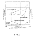
- FIG. 2 Shown in Fig. 2 are load characteristics of NO x and CO concentrations of the exhaust gas discharged from a combustor in the comparative example provided with only the first additive fuel supply device 7A and load characteristics of NO x and CO concentrations of the exhaust gas discharged from a combustor in the present example provided with the first additive fuel supply device 7A and the second additive fuel supply device 7B.
- H1 shows the allowable upper limit of NO x concentration
- H2 shows the allowable upper limit of CO concentration.
- the NO x concentration of the exhaust gas discharged from the combustor in the present example is lower than that of the exhaust gas discharged from the combustor in the comparative example in the entire load range.
- the additive fuel supply devices 7A and 7B are effective in reducing the NO x and the CO concentration of the exhaust gas.
- the CO concentration of the exhaust gas discharged from the combustor in the present example is below the allowable upper limit H2 of CO concentration in the entire load range, which proves that the additive fuel supply devices 7A and 7B are effective in reducing the CO concentration of the exhaust gas.
- the CO concentration of the exhaust gas generated by the combustor in the comparative example is higher than the allowable upper limit H2 of CO concentration at loads below a predetermined load E1. Therefore, the combustor in the comparative example should not be operated at loads below the predetermined load E1 from the viewpoint of environmental conservation.
- the two-stage additive fuel supply unit 7 including the additive fuel supply devices 7A and 7B expands the load range in which the combustor can operate without causing problems in environmental conservation.
Landscapes
- Engineering & Computer Science (AREA)
- Chemical & Material Sciences (AREA)
- Combustion & Propulsion (AREA)
- Mechanical Engineering (AREA)
- General Engineering & Computer Science (AREA)
Abstract
Description
- The present invention relates to a combustor for a gas turbine engine. More specifically, the present invention relates to a combustor for a gas turbine engine, capable of making the combustor of the gas turbine engine achieve desired stable, low-pollution combustion under partial load.
- Private power generation equipment has progressively come into wide use recently, and gas turbine engines are used widely as power units for private power generation equipment. Different time zones have different power demands, respectively, on private power generation equipment. Therefore, private power generation equipment does not operate always in a maximum-load operating mode and are often required to operate in a partial-load operating mode.
- Consequently, the gas turbine engine for private power generation equipment is required to maintain satisfactorily stable combustion and to reduce the rate of emission of harmful gases including NOx (nitrogen oxides) and CO (carbon monoxide) for environmental conservation.
- In order to meet the requirements, some techniques have been proposed previously, such as a first method that injects water or steam into a combustion chamber and a second method that reduces air for lean premixed combustion through engine extraction.
- The first method needs an additional mechanism for injecting water or steam into the combustion chamber. The additional mechanism enlarges the gas turbine engine and the gas turbine engine cannot reduce the rate of NOx emission greatly so as to compensate for the disadvantage of the additional mechanism.
- Although the second method can reduce the rate of NOx emission in a wide range of load on the gas turbine engine even in lean premixed combustion having a narrow stable combustion range, work necessary for extraction reduces the thermal efficiency of the gas turbine engine.
- The previously proposed techniques are described in
JP-A 8-261468 JP-A 10-196909 JP-A 2000-274689 - The present invention has been made in view of those problems in the related art and it is therefore an object of the present invention to provide a combustor for a gas turbine engine, capable of achieving stable combustion and of reducing the rate of emission of harmful substances, such as NOx and CO, in a wide range of load without enlarging the gas turbine engine, without complicating the constitution of the gas turbine engine and without reducing the thermal efficiency of the gas turbine engine.
- A combustor for a gas turbine engine of a lean premixed combustion type according to the present invention includes: a fuel jetting device configured to jet a premixed fuel into a combustion chamber so that the premixed fuel burns in a premixed combustion zone which is formed in the combustion chamber; and an additive fuel supply unit disposed downstream of the premixed combustion zone so as to additionally supply fuel into the combustion chamber, the additive fuel supply unit including first and second additive fuel supply devices disposed in a two-stage arrangement such that the second additive fuel supply device is positioned downstream of the first additive fuel supply device.
- In the combustor according to the present invention for a gas turbine engine, it is preferable that a main air passage formed in a liner head to supply air into the premixed combustion zone has a sectional area not lager than a sum of sectional areas of air passages in the first and second additive fuel supply devices of the additive fuel supply unit.
- In the combustor according to the present invention for a gas turbine engine, it is preferable that a sectional area of an air passage in the first additive fuel supply device is not larger than a sectional area of an air passage in the second additive fuel supply device.
- In the combustor according to the present invention for a gas turbine engine, it is preferable that the first and second additive fuel supply devices of the additive fuel supply unit are respectively provided with diffusion nozzles to supply fuel.
- The combustor according to the present invention for a gas turbine engine achieves desired stable, low-pollution combustion under load varying in a wide load range and discharges an exhaust gas including reduced amount of harmful substances, such as NOx and CO.
- The above and other objects, features and advantages of the present invention will become more apparent from the following description taken in connection with the accompanying drawings, in which:
- Fig. 1 is a schematic sectional view of a combustor U in a preferred embodiment according to the present invention for a gas turbine engine; and
- Fig. 2 is diagram comparatively showing the respective load characteristics of harmful gas emissions of a combustor in a present example of the present invention and of a combustor in a comparative example.
- A combustor in a preferred embodiment according to the present invention will be described by way of example with reference to Figs. 1 and 2.
- Referring to Fig. 1 showing a combustor U in a preferred embodiment according to the present invention included in a gas turbine engine, the combustor U has a combustor casing including a
flow sleeve 1, namely, an outer sleeve, and aninner tube 2, namely, an inner sleeve, extended inside theflow sleeve 1. - One end of the
flow sleeve 1 and one end of theinner tube 2 are closed by anend wall 3. The other end of theflow sleeve 1 is an air inlet 1a and the other end of theinner tube 2 is an exhaust outlet 2a. - The interior of the
inner tube 2 is divided into aliner head 4 on the side of theend wall 3 and acombustion chamber 5 on the side of the exhaust outlet 2a by apartition wall 2b having a shape resembling an annular plate disposed at a predetermined longitudinal position. - The
liner head 4 is provided with a predetermined number of openings 4a through which combustion air taken through the air inlet 1a into theflow sleeve 1 flows into theinner tube 2. Afuel jetting device 6 is disposed inside theliner head 4. Thefuel jetting device 6 prepares a premixed fuel by mixing fuel supplied by a fuel supply system, not shown, and combustion air and jets the premixed fuel into thecombustion chamber 5. The premixed fuel jetted by thefuel jetting device 6 burns in a predetermined premixed combustion zone V in thecombustion chamber 5. - The combustor U is provided with a two-stage additive
fuel supply unit 7 in addition to thefuel jetting device 6. The two-stage additivefuel supply unit 7 supplies fuel additionally into thecombustion chamber 5 while the gas turbine engine is in a partial-load operation. In Fig. 1, a character F indicates diffusion flames, namely, premixed flames. - The
fuel jetting device 6 includes apilot combustion unit 10 in a central part of an inner opening of thepartition wall 2b disposed on the upstream side of thecombustion chamber 5, and amain combustion unit 20 surrounding thepilot combustion unit 10. - The
pilot combustion unit 10 has a centralpilot fuel nozzle 11, and acombustion air passage 12 surrounding thepilot fuel nozzle 11. A premixed fuel produced by mixing fuel jetted through thepilot fuel nozzle 11 and combustion air is jetted into thecombustion chamber 5. - The
pilot fuel nozzle 11 has a closed end and a side wall provided withradial jetting holes 11a. Fuel is jetted radially through theradial jetting holes 11a. Thecombustion air passage 12 is defined by the outside surface of thepilot fuel nozzle 11 and the inside surface of an inner hat-shaped tube 13 surrounding thepilot fuel nozzle 11. Aswirler 14 is disposed at a predetermined position in thecombustion air passage 12. The fuel jetted into thecombustion air passage 12 through thepilot fuel nozzle 11 is mixed into swirling combustion air currents produced by theswirler 14. The premixed fuel flows into thecombustion chamber 5. - The
main combustion unit 20 includes amain fuel nozzle 21 and a main premixedfuel passage 22. A premixed fuel produced by mixing the fuel jetted through themain fuel nozzle 21 and combustion air flows through the main premixedfuel passage 22 into thecombustion chamber 5. - The
main fuel nozzle 21 surrounds the inner hat-shaped tube 13. The fuel is jetted through themain fuel nozzle 21 toward the inlet 22a of thepremixed fuel passage 22. - The main premixed
fuel passage 22 is defined by the outside surface of the inner hat-shaped tube 13 and an outer hat-shaped tube 23 of a diameter greater than that of the inner hat-shaped tube 13. A space between the flanges of the hat-shaped tubes premixed fuel passage 22. - A
swirler 24 is disposed in the inlet 22a of thepremixed fuel passage 22. - The open end of the outer hat-
shaped tube 23 is joined to the inside edge of thepartition wall 2b disposed inside theinner tube 2 to form apremixed fuel outlet 22b, namely, the outlet of the main premixed fuel passage. - A premixed fuel produced by mixing the fuel jetted through the
main fuel nozzle 21 and combustion air is swirled. The swirling premixed fuel is jetted through thepremixed fuel outlet 22b into the premixed combustion zone V. - Combustion air taken through the openings 4a of the
liner head 4 into theinner tube 2 flows through the mainpremixed fuel passage 22 and theswirler 14 into the premixed combustion zone V. The present specification defines the sum of the respective sectional areas of the mainpremixed fuel passage 22 and theswirler 14 as a main air passage area S. - Generally, there are limited lean air-fuel ratios that enable the gas turbine engine to achieve stable combustion at low rate of emission of NOx and CO under low loads. According to the present embodiment, the main air passage area S is determined such that the air-fuel ratio of the premixed fuel in the premixed combustion zone V while the gas turbine engine is in a partial-load operation under a predetermined load, such as a load equal to 50% of a maximum load, is nearly equal to the limited air-fuel ratio for an operation under a predetermined load nearly equal to a maximum load, such as a load equal to 80% of the maximum load. The main air passage area S is smaller than an ordinary main air passage area.
- The two-stage additive
fuel supply unit 7 supplies fuel additionally for after burning into a predetermined zone downstream of the premixed combustion zone V, in which stable low-NOx, low-CO combustion is carried out, in thecombustion chamber 5 during a partial-load operation to suppress the generation of NOx. The two-stage additivefuel supply unit 7 has a predetermined number of additivefuel supply tubes 31 penetrate parts corresponding to the predetermined zone of theinner tube 2 defining thecombustion chamber 5, and additivefuel supply nozzles 32 having end parts of a predetermined length inserted into the additivefuel supply tubes 31. - The additive
fuel supply nozzles 32 may be either of diffusion nozzles as shown in Fig. 1 and premixed combustion nozzles, not shown. - The two-stage additive
fuel supply unit 7 includes a first additivefuel supply device 7A and a second additivefuel supply device 7B. The first additive fuel supply device 7a and the second additivefuel supply device 7B are disposed at a first longitudinal distance L1 and a second longitudinal distance L2, respectively, from the premixedfuel outlet 22b. The distance L2 is greater than the distance L1. - The first distance L1, the second distance L2, the numbers of the
tubes 31 and the additivefuel supply nozzles 32 of the additivefuel supply devices 7a and 7B, the pattern of arrangement, such as a straight pattern or a zigzag pattern, of the additivefuel supply nozzles 32, the ratio between the main air passage area S and the sum of the sectional areas of the air passages of the two-stage additivefuel supply unit 7, and the ratio between the respective sectional areas of the first additivefuel supply device 7A and the second additivefuel supply device 7B are selectively determined so that the rate of emission of NOx and CO may be small and stable combustion can be achieved. - The ratio D1 of the main air passage area S to the total sectional area of the two-stage additive
fuel supply unit 7 is, for example, 5/5, and the ratio D2 of the total sectional area of the first additivefuel supply device 7A to the total sectional area of the second additivefuel supply device 7B is, for example, 4/6. - The ratio D1 is reduced to 4/6 or such to widen the range of low-load operation.
- The ratio D2 is reduced to 3/7 or such to widen the range of low-load operation.
- The main air passage area S of the combustor U in this embodiment is determined so that the combustor U can achieve stable combustion at a low rate of emission of NOx and CO while the gas turbine engine is in a partial-load operation, and the fuel additionally supplied by the two-stage additive
fuel supply unit 7 burns in thecombustion chamber 5. Therefore, a proper air-fuel ratio in accordance with a given load can be determined so that the generation of NOx and CO can be suppressed. - Thus the combustor U can maintain stable combustion at a low rate of emission of NOx and CO for the operation of the gas turbine in a wide load range.
- Performance of combustors in a present example according to the present invention and a comparative example will be described in connection with Fig. 2. Shown in Fig. 2 are load characteristics of NOx and CO concentrations of the exhaust gas discharged from a combustor in the comparative example provided with only the first additive
fuel supply device 7A and load characteristics of NOx and CO concentrations of the exhaust gas discharged from a combustor in the present example provided with the first additivefuel supply device 7A and the second additivefuel supply device 7B. In Fig. 2, H1 shows the allowable upper limit of NOx concentration, and H2 shows the allowable upper limit of CO concentration. - As obvious from Fig. 2, the NOx concentration of the exhaust gas discharged from the combustor in the present example is lower than that of the exhaust gas discharged from the combustor in the comparative example in the entire load range.
- It is known from Fig. 2 that the additive
fuel supply devices fuel supply devices fuel supply unit 7 including the additivefuel supply devices - Although the invention has been described in its preferred embodiment with a certain degree of particularity, obviously many changes and variations are possible therein. It is therefore to be understood that the present invention may be practiced otherwise than as specifically described herein without departing from the scope thereof.
Claims (5)
- A combustor for a gas turbine engine of a lean premixed combustion type, comprising:a fuel jetting device configured to jet a premixed fuel into a combustion chamber so that the premixed fuel burns in a premixed combustion zone which is formed in the combustion chamber; andan additive fuel supply unit disposed downstream of the premixed combustion zone so as to additionally supply fuel into the combustion chamber, the additive fuel supply unit including first and second additive fuel supply devices disposed in a two-stage arrangement such that the second additive fuel supply device is positioned downstream of the first additive fuel supply device.
- The combustor for a gas turbine engine according to claim 1, wherein a main air passage formed in a liner head to supply air into the premixed combustion zone has a sectional area not lager than a sum of sectional areas of air passages in the first and second additive fuel supply devices of the additive fuel supply unit.
- The combustor for a gas turbine engine according to claim 1, wherein a sectional area of an air passage in the first additive fuel supply device is not larger than a sectional area of an air passage in the second additive fuel supply device.
- The combustor for a gas turbine engine according to claim 2, wherein a sectional area of an air passage in the first additive fuel supply device is not larger than a sectional area of an air passage in the second additive fuel supply device.
- The combustor for a gas turbine engine according to any preceding claim, wherein the first and second additive fuel supply devices of the additive fuel supply unit are respectively provided with diffusion nozzles to supply fuel.
Applications Claiming Priority (1)
| Application Number | Priority Date | Filing Date | Title |
|---|---|---|---|
| JP2005308380A JP2007113888A (en) | 2005-10-24 | 2005-10-24 | Gas turbine engine combustor structure |
Publications (2)
| Publication Number | Publication Date |
|---|---|
| EP1777459A2 true EP1777459A2 (en) | 2007-04-25 |
| EP1777459A3 EP1777459A3 (en) | 2009-10-07 |
Family
ID=37667324
Family Applications (1)
| Application Number | Title | Priority Date | Filing Date |
|---|---|---|---|
| EP06255437A Withdrawn EP1777459A3 (en) | 2005-10-24 | 2006-10-23 | Combustor for gas turbine |
Country Status (3)
| Country | Link |
|---|---|
| US (1) | US20070089419A1 (en) |
| EP (1) | EP1777459A3 (en) |
| JP (1) | JP2007113888A (en) |
Cited By (4)
| Publication number | Priority date | Publication date | Assignee | Title |
|---|---|---|---|---|
| GB2446164A (en) * | 2007-02-05 | 2008-08-06 | Ntnu Technology Transfer As | Gas Turbine Emissions Reduction with Premixed and Diffusion Combustion |
| WO2009038625A3 (en) * | 2007-09-14 | 2010-05-06 | Siemens Energy, Inc. | A multi-stage axial combustion system |
| WO2013043076A1 (en) * | 2011-09-22 | 2013-03-28 | General Electric Company | Combustor and method for supplying fuel to a combustor |
| EP2914907B1 (en) * | 2012-11-02 | 2018-07-04 | Exxonmobil Upstream Research Company | System and method for diffusion combustion with fuel-diluent mixing in a stoichiometric exhaust gas recirculation gas turbine system |
Families Citing this family (40)
| Publication number | Priority date | Publication date | Assignee | Title |
|---|---|---|---|---|
| US8387398B2 (en) * | 2007-09-14 | 2013-03-05 | Siemens Energy, Inc. | Apparatus and method for controlling the secondary injection of fuel |
| US8689559B2 (en) * | 2009-03-30 | 2014-04-08 | General Electric Company | Secondary combustion system for reducing the level of emissions generated by a turbomachine |
| EP2726788B1 (en) * | 2011-06-28 | 2020-03-25 | General Electric Company | Rational late lean injection |
| US8919137B2 (en) * | 2011-08-05 | 2014-12-30 | General Electric Company | Assemblies and apparatus related to integrating late lean injection into combustion turbine engines |
| WO2013073984A1 (en) * | 2011-11-17 | 2013-05-23 | General Electric Company | Turbomachine combustor assembly and method of operating a turbomachine |
| US20130213046A1 (en) * | 2012-02-16 | 2013-08-22 | General Electric Company | Late lean injection system |
| US20150184858A1 (en) * | 2012-10-01 | 2015-07-02 | Peter John Stuttford | Method of operating a multi-stage flamesheet combustor |
| US9897317B2 (en) | 2012-10-01 | 2018-02-20 | Ansaldo Energia Ip Uk Limited | Thermally free liner retention mechanism |
| US10060630B2 (en) | 2012-10-01 | 2018-08-28 | Ansaldo Energia Ip Uk Limited | Flamesheet combustor contoured liner |
| US10378456B2 (en) | 2012-10-01 | 2019-08-13 | Ansaldo Energia Switzerland AG | Method of operating a multi-stage flamesheet combustor |
| US20140090400A1 (en) | 2012-10-01 | 2014-04-03 | Peter John Stuttaford | Variable flow divider mechanism for a multi-stage combustor |
| EP2933561A4 (en) * | 2012-12-13 | 2016-08-24 | Kawasaki Heavy Ind Ltd | GAS TURBINE COMBUSTION CHAMBER ACCEPTING MULTIPLE FUEL |
| WO2014201135A1 (en) * | 2013-06-11 | 2014-12-18 | United Technologies Corporation | Combustor with axial staging for a gas turbine engine |
| US20150052905A1 (en) * | 2013-08-20 | 2015-02-26 | General Electric Company | Pulse Width Modulation for Control of Late Lean Liquid Injection Velocity |
| US20150159877A1 (en) * | 2013-12-06 | 2015-06-11 | General Electric Company | Late lean injection manifold mixing system |
| US20150167980A1 (en) * | 2013-12-18 | 2015-06-18 | Jared M. Pent | Axial stage injection dual frequency resonator for a combustor of a gas turbine engine |
| WO2015037295A1 (en) * | 2014-06-12 | 2015-03-19 | 川崎重工業株式会社 | Multi-fuel-supporting gas-turbine combustor |
| JP6516996B2 (en) * | 2014-10-10 | 2019-05-22 | 川崎重工業株式会社 | Combustor and gas turbine engine |
| JP2016109309A (en) * | 2014-12-02 | 2016-06-20 | 川崎重工業株式会社 | Combustor for gas turbine, and gas turbine |
| JP5993046B2 (en) * | 2015-02-13 | 2016-09-14 | 川崎重工業株式会社 | Multi-fuel compatible gas turbine combustor |
| US10480792B2 (en) * | 2015-03-06 | 2019-11-19 | General Electric Company | Fuel staging in a gas turbine engine |
| CA2994954C (en) * | 2015-08-07 | 2021-04-20 | Red Valve Company, Inc. | Free flow collar for control valves |
| JP6039033B2 (en) * | 2015-09-24 | 2016-12-07 | 新潟原動機株式会社 | Gas turbine combustor |
| US9938903B2 (en) * | 2015-12-22 | 2018-04-10 | General Electric Company | Staged fuel and air injection in combustion systems of gas turbines |
| US9989260B2 (en) * | 2015-12-22 | 2018-06-05 | General Electric Company | Staged fuel and air injection in combustion systems of gas turbines |
| CN105423344B (en) * | 2016-01-12 | 2017-12-29 | 西北工业大学 | A kind of flame tube structure of ground combustion machine combustion chamber |
| US10605459B2 (en) * | 2016-03-25 | 2020-03-31 | General Electric Company | Integrated combustor nozzle for a segmented annular combustion system |
| US10584876B2 (en) * | 2016-03-25 | 2020-03-10 | General Electric Company | Micro-channel cooling of integrated combustor nozzle of a segmented annular combustion system |
| US10584880B2 (en) * | 2016-03-25 | 2020-03-10 | General Electric Company | Mounting of integrated combustor nozzles in a segmented annular combustion system |
| US11187415B2 (en) * | 2017-12-11 | 2021-11-30 | General Electric Company | Fuel injection assemblies for axial fuel staging in gas turbine combustors |
| US11994292B2 (en) | 2020-08-31 | 2024-05-28 | General Electric Company | Impingement cooling apparatus for turbomachine |
| US11460191B2 (en) | 2020-08-31 | 2022-10-04 | General Electric Company | Cooling insert for a turbomachine |
| US11994293B2 (en) | 2020-08-31 | 2024-05-28 | General Electric Company | Impingement cooling apparatus support structure and method of manufacture |
| US11371702B2 (en) | 2020-08-31 | 2022-06-28 | General Electric Company | Impingement panel for a turbomachine |
| US11614233B2 (en) | 2020-08-31 | 2023-03-28 | General Electric Company | Impingement panel support structure and method of manufacture |
| US11255545B1 (en) | 2020-10-26 | 2022-02-22 | General Electric Company | Integrated combustion nozzle having a unified head end |
| US11846426B2 (en) | 2021-06-24 | 2023-12-19 | General Electric Company | Gas turbine combustor having secondary fuel nozzles with plural passages for injecting a diluent and a fuel |
| CN114353121B (en) * | 2022-01-18 | 2022-12-20 | 上海交通大学 | A multi-nozzle fuel injection method for gas turbine |
| US11767766B1 (en) | 2022-07-29 | 2023-09-26 | General Electric Company | Turbomachine airfoil having impingement cooling passages |
| DE102022208339A1 (en) * | 2022-08-10 | 2024-02-15 | Rolls-Royce Deutschland Ltd & Co Kg | Combustion chamber arrangement for operation with liquid and/or gaseous fuel, gas turbine arrangement and method |
Family Cites Families (18)
| Publication number | Priority date | Publication date | Assignee | Title |
|---|---|---|---|---|
| US1793640A (en) * | 1926-04-26 | 1931-02-24 | Holzwarth Gas Turbine Co | Combustion engine |
| US2679295A (en) * | 1949-12-30 | 1954-05-25 | Gen Electric | Helicopter blade jet combustion chamber |
| BE503026A (en) * | 1950-07-17 | |||
| US4928481A (en) * | 1988-07-13 | 1990-05-29 | Prutech Ii | Staged low NOx premix gas turbine combustor |
| US4910957A (en) * | 1988-07-13 | 1990-03-27 | Prutech Ii | Staged lean premix low nox hot wall gas turbine combustor with improved turndown capability |
| GB9023004D0 (en) * | 1990-10-23 | 1990-12-05 | Rolls Royce Plc | A gas turbine engine combustion chamber and a method of operating a gas turbine engine combustion chamber |
| EP0540167A1 (en) * | 1991-09-27 | 1993-05-05 | General Electric Company | A fuel staged premixed dry low NOx combustor |
| US5452574A (en) * | 1994-01-14 | 1995-09-26 | Solar Turbines Incorporated | Gas turbine engine catalytic and primary combustor arrangement having selective air flow control |
| JP2950720B2 (en) * | 1994-02-24 | 1999-09-20 | 株式会社東芝 | Gas turbine combustion device and combustion control method therefor |
| DE4416650A1 (en) * | 1994-05-11 | 1995-11-16 | Abb Management Ag | Combustion process for atmospheric combustion plants |
| DE4441235A1 (en) * | 1994-11-19 | 1996-05-23 | Abb Management Ag | Combustion chamber with multi-stage combustion |
| US6047550A (en) * | 1996-05-02 | 2000-04-11 | General Electric Co. | Premixing dry low NOx emissions combustor with lean direct injection of gas fuel |
| GB9609317D0 (en) * | 1996-05-03 | 1996-07-10 | Rolls Royce Plc | A combustion chamber and a method of operation thereof |
| FR2779807B1 (en) * | 1998-06-11 | 2000-07-13 | Inst Francais Du Petrole | VARIABLE GEOMETRY GAS TURBINE COMBUSTION CHAMBER |
| GB9818160D0 (en) * | 1998-08-21 | 1998-10-14 | Rolls Royce Plc | A combustion chamber |
| GB9911867D0 (en) * | 1999-05-22 | 1999-07-21 | Rolls Royce Plc | A combustion chamber assembly and a method of operating a combustion chamber assembly |
| GB9915770D0 (en) * | 1999-07-07 | 1999-09-08 | Rolls Royce Plc | A combustion chamber |
| US20060107667A1 (en) * | 2004-11-22 | 2006-05-25 | Haynes Joel M | Trapped vortex combustor cavity manifold for gas turbine engine |
-
2005
- 2005-10-24 JP JP2005308380A patent/JP2007113888A/en active Pending
-
2006
- 2006-10-18 US US11/582,295 patent/US20070089419A1/en not_active Abandoned
- 2006-10-23 EP EP06255437A patent/EP1777459A3/en not_active Withdrawn
Cited By (7)
| Publication number | Priority date | Publication date | Assignee | Title |
|---|---|---|---|---|
| GB2446164A (en) * | 2007-02-05 | 2008-08-06 | Ntnu Technology Transfer As | Gas Turbine Emissions Reduction with Premixed and Diffusion Combustion |
| WO2009038625A3 (en) * | 2007-09-14 | 2010-05-06 | Siemens Energy, Inc. | A multi-stage axial combustion system |
| US7886539B2 (en) | 2007-09-14 | 2011-02-15 | Siemens Energy, Inc. | Multi-stage axial combustion system |
| WO2013043076A1 (en) * | 2011-09-22 | 2013-03-28 | General Electric Company | Combustor and method for supplying fuel to a combustor |
| US9388987B2 (en) | 2011-09-22 | 2016-07-12 | General Electric Company | Combustor and method for supplying fuel to a combustor |
| DE112011105655B4 (en) | 2011-09-22 | 2023-05-25 | General Electric Company | Burner and method of supplying fuel to a burner |
| EP2914907B1 (en) * | 2012-11-02 | 2018-07-04 | Exxonmobil Upstream Research Company | System and method for diffusion combustion with fuel-diluent mixing in a stoichiometric exhaust gas recirculation gas turbine system |
Also Published As
| Publication number | Publication date |
|---|---|
| EP1777459A3 (en) | 2009-10-07 |
| JP2007113888A (en) | 2007-05-10 |
| US20070089419A1 (en) | 2007-04-26 |
Similar Documents
| Publication | Publication Date | Title |
|---|---|---|
| US20070089419A1 (en) | Combustor for gas turbine engine | |
| JP4658471B2 (en) | Method and apparatus for reducing combustor emissions in a gas turbine engine | |
| JP4906689B2 (en) | Burner, combustion device, and method for modifying combustion device | |
| EP1843099B1 (en) | Gas turbine combustor and operating method | |
| US7426833B2 (en) | Gas turbine combustor and fuel supply method for same | |
| JP3335713B2 (en) | Gas turbine combustor | |
| US8327643B2 (en) | Staging fuel nozzle | |
| JP2018004138A (en) | Gas turbine combustor | |
| KR20150065782A (en) | Combustor with radially staged premixed pilot for improved operability | |
| KR20100080428A (en) | Dln dual fuel primary nozzle | |
| JP2005345094A (en) | Premix burner with impingement cooled centerbody and cooling method for centerbody | |
| JP4086767B2 (en) | Method and apparatus for reducing combustor emissions | |
| US7127899B2 (en) | Non-swirl dry low NOx (DLN) combustor | |
| US7059135B2 (en) | Method to decrease combustor emissions | |
| JP2005106305A (en) | Nozzle for fuel combustion and fuel supply method for gas turbine combustor | |
| JP4400314B2 (en) | Gas turbine combustor and fuel supply method for gas turbine combustor | |
| JPH0814565A (en) | Gas turbine combustor | |
| JPH08135970A (en) | Gas turbine combustor | |
| JPH09166326A (en) | Gas turbine combustor | |
| JP3499004B2 (en) | Gas turbine combustor | |
| JP2006090602A (en) | Lobe mixer and premixer | |
| JPS61110817A (en) | Combustion device | |
| JPH07260149A (en) | Gas turbine combustor | |
| JP2001263093A (en) | Gas turbine combustor | |
| HK1130877B (en) | Burner, combusting apparatus, remodeling method for combusting apparatus |
Legal Events
| Date | Code | Title | Description |
|---|---|---|---|
| PUAI | Public reference made under article 153(3) epc to a published international application that has entered the european phase |
Free format text: ORIGINAL CODE: 0009012 |
|
| 17P | Request for examination filed |
Effective date: 20061108 |
|
| AK | Designated contracting states |
Kind code of ref document: A2 Designated state(s): AT BE BG CH CY CZ DE DK EE ES FI FR GB GR HU IE IS IT LI LT LU LV MC NL PL PT RO SE SI SK TR |
|
| AX | Request for extension of the european patent |
Extension state: AL BA HR MK YU |
|
| PUAL | Search report despatched |
Free format text: ORIGINAL CODE: 0009013 |
|
| AK | Designated contracting states |
Kind code of ref document: A3 Designated state(s): AT BE BG CH CY CZ DE DK EE ES FI FR GB GR HU IE IS IT LI LT LU LV MC NL PL PT RO SE SI SK TR |
|
| AX | Request for extension of the european patent |
Extension state: AL BA HR MK RS |
|
| 17Q | First examination report despatched |
Effective date: 20100111 |
|
| AKX | Designation fees paid |
Designated state(s): DE FR GB IT |
|
| STAA | Information on the status of an ep patent application or granted ep patent |
Free format text: STATUS: THE APPLICATION IS DEEMED TO BE WITHDRAWN |
|
| 18D | Application deemed to be withdrawn |
Effective date: 20100522 |