EP1777146A2 - Seitenwandkonstruktion für Personenkraftfahrzeuge - Google Patents
Seitenwandkonstruktion für Personenkraftfahrzeuge Download PDFInfo
- Publication number
- EP1777146A2 EP1777146A2 EP06021587A EP06021587A EP1777146A2 EP 1777146 A2 EP1777146 A2 EP 1777146A2 EP 06021587 A EP06021587 A EP 06021587A EP 06021587 A EP06021587 A EP 06021587A EP 1777146 A2 EP1777146 A2 EP 1777146A2
- Authority
- EP
- European Patent Office
- Prior art keywords
- reinforcing element
- side wall
- construction according
- vehicle
- wall construction
- Prior art date
- Legal status (The legal status is an assumption and is not a legal conclusion. Google has not performed a legal analysis and makes no representation as to the accuracy of the status listed.)
- Granted
Links
- 230000003014 reinforcing effect Effects 0.000 claims abstract description 58
- 238000010276 construction Methods 0.000 claims description 33
- 238000003466 welding Methods 0.000 description 8
- 238000000034 method Methods 0.000 description 3
- 230000002787 reinforcement Effects 0.000 description 3
- 230000015572 biosynthetic process Effects 0.000 description 2
- 230000000903 blocking effect Effects 0.000 description 2
- 238000005755 formation reaction Methods 0.000 description 2
- 238000009434 installation Methods 0.000 description 2
- 238000004519 manufacturing process Methods 0.000 description 2
- 239000002184 metal Substances 0.000 description 2
- 238000005452 bending Methods 0.000 description 1
- 238000005253 cladding Methods 0.000 description 1
- 239000002131 composite material Substances 0.000 description 1
- 230000008094 contradictory effect Effects 0.000 description 1
- 230000001419 dependent effect Effects 0.000 description 1
- 238000005516 engineering process Methods 0.000 description 1
- 238000012986 modification Methods 0.000 description 1
- 230000004048 modification Effects 0.000 description 1
- 239000000565 sealant Substances 0.000 description 1
- 230000000007 visual effect Effects 0.000 description 1
Images



Classifications
-
- B—PERFORMING OPERATIONS; TRANSPORTING
- B62—LAND VEHICLES FOR TRAVELLING OTHERWISE THAN ON RAILS
- B62D—MOTOR VEHICLES; TRAILERS
- B62D25/00—Superstructure or monocoque structure sub-units; Parts or details thereof not otherwise provided for
- B62D25/04—Door pillars ; windshield pillars
Definitions
- the invention is in the field of passenger car body construction and relates to a side wall construction for passenger vehicles with an A-pillar, which has a tubular, closed in cross-section reinforcing element at least in the region of the receptacle.
- the frame construction consists of several subframes, which in turn consist of frame elements which are interconnected via node elements.
- the frame elements for example, the A-pillar - and the node elements by hydraulic hydroforming (so-called "hydroforming / hydroforming process") prefabricated cross-section optimized.
- the frame construction by covering parts, such as an outer side wall, completed to a vehicle body. Between the A-pillars of the opposite sides of the vehicle in the area between the vehicle front wall and the roof in the DE 195 06 160 A1 Windshield not shown mounted.
- a carrier profile is formed from two or more profile-forming sheet metal parts by means of welded joints, which serves as an A-pillar.
- the A-pillars are usually covered on the passenger side by a panel.
- the hollow support profile thus formed must have a comparatively large cross-section.
- the present invention is based on the object of specifying a side wall construction with which a considerable improvement of the front view (also referred to below as the viewing angle) is created.
- the reinforcing member when using an A-pillar, which has at least in the region of the receptacle, a tubular, seamless in cross-section and closed reinforcing member, the reinforcing member has a mounting surface for the lateral region of a windshield.
- the reinforcing element has an additional function with its upper outer surface an assembly element. or to form support surface for the edge or the side portion of the windshield.
- the tubular profile of the reinforcing element thus acts as an internal reinforcement of the A-pillar or in this side wall region of a substantially conventional vehicle body.
- the reinforcing element may particularly preferably be produced by hydraulic hydroforming (so-called “hydroforming / hydroforming process"). With this method, almost all desired shapes, variable cross-sections and formations can be formed.
- the reinforcing element is characterized by a particularly high strength or rigidity, so that at the same loads a comparison with the above-described composite hollow section carrier overall much smaller diameter or cross-sectional area of the reinforcing element sufficient is.
- the potential of the thereby possible enlargement of the available field of view is utilized in that the windshield is mounted on a so far laterally outwardly displaceable mounting surface of the reinforcing element. This advantageously results in a much larger viewing angle for the driver.
- Another essential advantage of the invention is that a directly connected to the mounting surface of the reinforcing element, for example, glued, windshield is largely fixed torsion and stress-free.
- the reinforcing element extends with its one end to the vehicle front wall.
- the reinforcing element may extend with its other end to the vehicle roof.
- the reinforcing element at its end facing the vehicle front wall and / or the roof area have weldable connection parts according to a preferred embodiment of the invention.
- a design of the invention particularly appealing and monteteetechnisch preferred embodiment provides that the reinforcing element is covered by the upper portion of an outer side wall, wherein the side wall is provided with a shoulder under which the reinforcing element protrudes toward the vehicle front wall to release the mounting surface.
- the shoulder may preferably form a contact surface for the upper, substantially horizontally extending edge region of the windshield.
- the reinforcing element is provided with radially outwardly facing elevations, which serve as connection zones.
- the elevations can serve as welding zones or for setting welds.
- the elevations may preferably be formed by hydroforming forms.
- the reinforcing element may particularly preferably be connected to a plurality of planar components, for example by welding, in that the projection penetrates at least one recess in at least one component to be connected, whereby this component is virtually “sandwiched" between the reinforcing element and another connected to it, for example welded, outer component is located.
- the intermediate component is provided with a cutout, perforations or generally recesses through which the survey extends at least partially.
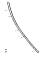
- FIG. 1 shows a reinforcing element 1 for use in a sidewall construction according to the invention.
- the reinforcing element has an installation position Front end oriented to the vehicle end wall 2 and an end oriented to the roof area 3.
- the reinforcing element is formed in this embodiment of a hydroformed, continuous and lijnsnaht- or longitudinally connection-free tube, but could just as well consist of a curved extruded profile.
- the tube has local embossments or elevations 4.
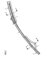
- the reinforcing element 1 is provided at its ends 2 and 3 with connecting parts 5, 6.
- the connecting parts which are also referred to as gusset plates, have corresponding contours which correspond to the associated characteristics or elevations 4, the elevations preferably being used for producing welded connections between reinforcing element 1 and connecting parts 5, 6.
- connection part 6 is used for connection to the roof frame or the roof structure of the vehicle, not shown, and for profile formation or profile connection to the outer side wall.
- the front-side connection part or gusset plate 5 is used for connection, for example, for welding, with the front wall of the vehicle also not shown.
- the reinforcing element 1 is a tube-shaped, fully-closed tubular reinforcement and therefore has a comparatively small cross-section 7 of extremely high strength, in particular torsional strength and bending stiffness.
- the welded gusset plate 5 can be seen, which is welded to a side part or the end wall 8.
- FIG. 4 The sectional view shown in Figure 4 along the line C-C in Figure 2 illustrates how the reinforcing element 1 is connected in the roof area with the gusset plate 6, which serves for connection to the roof structure or laterally rearwardly extending roof frame.
- the outer upper region of a vehicle side wall is connected to the reinforcing element 1.
- the vehicle roof 14 can then likewise be connected directly to the reinforcing element by further laser welding seams and / or spot welds 12. Further, the side wall 11 is welded to the wegeruitenden part of the gusset plate 6.
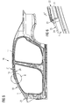
- Figure 5 apparent side wall construction 16 thus comprises as essential parts of the actual outer side wall 11 and the reinforcing element 1, the side wall 11 in the region of the front left side support member - usually referred to as A-pillar - 18 reinforced.
- the reinforcing element 1 extends with its end 2 in the front region 20 of the end wall and with its end 3 in the rear region 21 to the roof 14th
- FIG. 6 shows the detail X from FIG. 5. It can be seen here that the reinforcing element 1 protrudes under a step or a shoulder 23 in the upper region 22 of the side wall 11, so that the outer surface 24 of the reinforcing element 1 is accessible there is still described manner as a mounting surface 25 for a windscreen to be glued.
- the windshield gets - with the interposition of appropriate sealant - on the paragraph 23 in Appendix.
- FIG. 7 shows in a perspective view a supplementary overview in which one recognizes the receptacle 26 formed by the reinforcing element 1 and a flange of the outer side wall 11 or mounting surface 25 for the side windshield region (not shown).
- the receptacle 26 formed by the reinforcing element 1 and a flange of the outer side wall 11 or mounting surface 25 for the side windshield region (not shown).
- FIG. 8 a conventional design and a sidewall construction according to the invention are shown in comparison. Due to the comparatively thin design of the reinforcing element 1 and the directly conforming and laser welding seams and / or welds 30 attached outer side wall 11 creates a comparatively low the driver's view (hereinafter also called the viewing angle) blocking dead angle ⁇ .
- the viewing angle the driver's view
- the A-pillar region may be internally provided with a cladding 32 which, however, contributes to a slight increase in the angle blocking the viewing angle (i.e., the blind spot).
- the field of vision or the viewing angle for the vehicle driver is significantly widened, in particular at the critical front areas of the A-pillar. This contributes to a substantial increase in the safety, in particular of the weaker road users, such as passers-by and cyclists.
- Figure 9 finally shows a section of the side wall construction in the region of a front door hinge 40 with reinforcing plates 41 for hinge attachment and with the reinforcing element 1. It can be seen here the elevations or characteristics 4 of the reinforcing element 1 at areas suitable for connection to other construction elements, namely eg with the o.g. Reinforcing plates 41 - are provided.
- the reinforcing element 1 has an outward elevation or embossment 4 which penetrates a recess 43 of the reinforcing plate 41 therebetween, so that the reinforcing element 1 there is laser welded 45 can be welded to the outer side wall 11.
- the possibility of widening the viewing angle is also ensured if highly loaded connection points on the A-pillar according to the conventional design would require a profile cross-section and / or wall thickness increases.
- the invention is not limited to the specific construction of the side wall shown in the preceding figures. Rather, just this side wall can be modified depending on the specific type of vehicle in any way, without departing from the basic principle of the invention.
Landscapes
- Engineering & Computer Science (AREA)
- Chemical & Material Sciences (AREA)
- Combustion & Propulsion (AREA)
- Transportation (AREA)
- Mechanical Engineering (AREA)
- Body Structure For Vehicles (AREA)
- Escalators And Moving Walkways (AREA)
Abstract
Description
- Die Erfindung liegt auf dem Gebiet des Personenkraftwagen-Karosseriebaus und betrifft eine Seitenwandkonstruktion für Personenkraftfahrzeuge mit einer A-Säule, die zumindest im Bereich der Aufnahme ein rohrförmiges, im Querschnitt geschlossenes Verstärkungselement aufweist.
- Aus der
Deutschen Patentanmeldung DE 195 06 160 A1 geht eine derartige Seitenwandkonstruktion hervor, die Teil einer Rahmenkonstruktion ist. Die Rahmenkonstruktion besteht aus mehreren Teilrahmen, die ihrerseits aus Rahmenelementen bestehen, die über Knotenelemente miteinander verbunden sind. Dabei sind zumindest ein Teil der Rahmenelemente - beispielsweise die A-Säule - und die Knotenelemente durch hydraulisches Innenhochdruck-Umformen (so genanntes "Hydroforming / IHU-Verfahren") querschnittsoptimiert vorgefertigt. Die Rahmenkonstruktion durch Verkleidungsteile, wie zum Beispiel einer äußeren Seitenwand, zu einer Fahrzeugkarosserie komplettiert. Zwischen den A-Säulen der gegenüberliegenden Fahrzeugseiten wird im Bereich zwischen der Fahrzeugstirnwand und dem Dach eine in derDE 195 06 160 A1 nicht näher dargestellte Windschutzscheibe montiert. - Bei anderen Konstruktionen ist aus zwei oder mehr profilbildenden Blechteilen mittels Schweißverbindungen ein Trägerprofil gebildet, das als A-Säule dient. Die A-Säulen sind üblicherweise Fahrgastinnenraum-seitig von einer Blende verdeckt. Um die erforderliche Steifigkeit und Torsionsfestigkeit der Karosserie zu gewährleisten, muss das so gebildete hohle Trägerprofil einen vergleichsweise großen Querschnitt aufweisen. Damit schränkt diese A-Säulenkonstruktion die Sicht des Fahrzeugführers nach vorn erheblich ein.
- An heutige Fahrzeugkarosserien werden immer anspruchsvollere Anforderungen gestellt, die sich sowohl nach Sicherheits- und Festigkeitskriterien aber auch aus Designaspekten und dem Kundengeschmack ergeben. Diese Anforderungen sind häufig gegensätzlich und stellen deshalb besondere Herausforderungen an den modernen Karosseriebau. Einen besonders wichtiger Aspekt ist dabei der Schutz und die Gefahrvermeidung für andere Verkehrsteilnehmer, insbesondere Fußgänger. Hier besteht neben einem optimierten Crashverhalten der Fahrzeugkarosserie eine ganz wesentliche Anforderung darin, für den Fahrzeugführer eine möglichst gute Sicht nach außen zu ermöglichen, um andere Verkehrsteilnehmer - insbesondere Fußgänger und Radfahrer - frühzeitig und gut erkennen zu können.
- Der vorliegenden Erfindung liegt vor diesem Hintergrund nun die Aufgabe zugrunde, eine Seitenwandkonstruktion anzugeben, mit der eine erhebliche Verbesserung der frontseitigen Sicht (nachfolgend auch als Sichtwinkel bezeichnet) geschaffen ist.
- Erfindungsgemäß wird diese Aufgabe durch eine Seitenwandkonstruktion mit den Merkmalen des Patentanspruchs 1 gelöst.
- Demgemäß ist vorgesehen, dass bei Verwendung einer A-Säule, die zumindest im Bereich der Aufnahme ein rohrförmiges, im Querschnitt nahtfreies und geschlossenes Verstärkungselement aufweist, das Verstärkungselement eine Montagefläche für den seitlichen Bereich einer Windschutzscheibe aufweist.
- Vorteilhafte Ausgestaltungen und Weiterbildungen der Erfindung sind Gegenstand der Unteransprüche sowie der Beschreibung unter Bezugnahme auf die Zeichnung.
- Die der vorliegenden Erfindung zugrunde liegende Idee besteht unter anderem darin, bei einer Seitenwandkonstruktion, bei der die Fahrzeugkarosserie gezielt im Bereich der seitlichen Frontscheibenauflage mit einem sehr festen und starren Zusatzkörper (Verstärkungselement) verstärkt ist, das Verstärkungselement in Zusatzfunktion mit seiner oberen Außenfläche eine Montage- oder Auflagefläche für den Rand bzw. den Seitenbereich der Windschutzscheibe bilden zu lassen.
- Das rohrförmige Profil des Verstärkungselements wirkt somit als innenliegende Verstärkung der A-Säule bzw. in diesem Seitenwandbereich einer im Wesentlichen herkömmlichen Fahrzeugkarosserie. Das Verstärkungselement kann besonders bevorzugt durch hydraulisches Innenhochdruck-Umformen (so genanntes "Hydroforming / IHU-Verfahren") hergestellt sein. Mit diesem Verfahren lassen sich annähernd alle gewünschten Formen, variable Querschnitte und Ausformungen bilden. Durch seinen vollgeschlossenen Querschnitt zeichnet sich das Verstärkungselement durch eine besonders hohe Festigkeit bzw. Steifigkeit aus, so dass bei gleichen Belastungen ein gegenüber dem eingangs beschriebenen zusammengesetzten Hohlprofilträger insgesamt wesentlich geringerer Durchmesser bzw. Querschnittsfläche des Verstärkungselements ausreichend ist. Das Potential der dadurch möglichen Vergrößerung des zur Verfügung stehenden Sichtbereichs wird dadurch genutzt, dass die Windschutzscheibe an einer insoweit seitlich nach außen verlagerbaren Montagefläche des Verstärkungselements montiert ist. Dadurch ergibt sich vorteilhafterweise ein wesentlich vergrößerter Sichtwinkel für den Fahrzeugführer.
- Ein weiterer wesentlicher Vorteil der Erfindung besteht darin, dass eine unmittelbar mit der Montagefläche des Verstärkungselementes verbundene, beispielsweise verklebte, Windschutzscheibe weitestgehend verwindungs- und spannungsfrei fixiert ist.
- Konstruktiv bevorzugt erstreckt sich das Verstärkungselement mit seinem einen Ende bis zur Fahrzeugstirnwand. Alternativ oder zusätzlich kann sich das Verstärkungselement mit seinem anderen Ende bis zum Fahrzeugdach erstrecken. Zur fertigungstechnisch einfachen und zuverlässigen Verbindung des Verstärkungselementes mit der übrigen Fahrzeugkarosserie kann nach einer bevorzugten Ausgestaltung der Erfindung das Verstärkungselement an seinem der Fahrzeugstirnwand und/oder dem Dachbereich zugewandten Ende schweißbare Anbindungsteile aufweisen.
- Eine vom Design her besonders ansprechende und montagetechnisch bevorzugte Ausgestaltung der Erfindung sieht vor, dass das Verstärkungselement vom oberen Bereich einer äußeren Seitenwand verdeckt ist, wobei die Seitenwand mit einem Absatz versehen ist, unter dem das Verstärkungselement zur Fahrzeugstirnwand hin unter Freigabe der Montagefläche hervortritt. Der Absatz kann bevorzugt eine Anlagefläche für den oberen, im Wesentlichen horizontal verlaufenden Randbereich der Windschutzscheibe bilden.
- Besonders bevorzugt ist das Verstärkungselement mit radial nach außen weisenden Erhebungen versehen, die als Verbindungszonen dienen. Insbesondere können die Erhebungen als Schweißzonen oder zum Setzen von Schweißpunkten dienen. Die Erhebungen können bevorzugt durch Hydroforming gebildete Ausprägungen sein.
- Das Verstärkungselement kann fertigungstechnisch besonders bevorzugt mit mehreren flächigen Bauteilen verbunden, beispielsweise verschweißt sein, indem die Erhebung mindestens eine Ausnehmung in mindestens einem zu verbindenden Bauteil durchdringt, wobei dieses Bauteil sich quasi "sandwichartig" zwischen dem Verstärkungselement und einem weiteren, mit diesem verbundenen, beispielsweise verschweißten, äußeren Bauteil befindet. Dabei ist das dazwischenliegende Bauteil mit einem Ausschnitt, Lochungen oder allgemein Ausnehmungen versehen, durch die sich die Erhebung mindestens teilweise erstreckt.
- Die Erfindung wird nachfolgend anhand der in den schematischen Figuren der Zeichnung angegebenen Ausführungsbeispiele näher erläutert. Es zeigen dabei:
- Figur 1
- ein Verstärkungselement für eine erfindungsgemäße Seitenwandkonstruktion;
- Figur 2
- das Verstärkungselement gemäß Figur 1 mit Anbindungsteilen;
- Figur 3
- den Querschnitt entlang der Linie B-B in Figur 2;
- Figur 4
- den Querschnitt entlang der Linie C-C in Figur 2;
- Figur 5
- eine erfindungsgemäße Seitenwandkonstruktion in Seitenansicht;
- Figur 6
- die Einzelheit X aus Figur 5;
- Figur 7
- in perspektivischer Ansicht den rechten oberen Bereich der Frontscheibenaufnahme eines Fahrzeuges mit einer erfindungsgemäßen Seitenwandkonstruktion;
- Figur 8
- zur Verdeutlichung der Sichtwinkelverbesserung eine Darstellung der Verhältnisse bei einer erfindungsgemäßen Ausgestaltung einer Seitenwandkonstruktion im Vergleich zu einer konventionellen Ausgestaltung;
- Figur 9
- einen Ausschnitt aus einer erfindungsgemäßen Seitenwandkonstruktion und
- Figur 10
- einen Querschnitt entlang der Linie D-D in Figur 9.
- In allen Figuren der Zeichnung sind gleiche und funktionsgleiche Merkmale und Elemente - sofern nichts Anderes angegeben ist - mit denselben Bezugszeichen versehen.
- Figur 1 zeigt ein Verstärkungselement 1 zur Verwendung in einer erfindungsgemäßen Seitenwandkonstruktion. Das Verstärkungselement weist ein in Einbaulage frontseitig zur Fahrzeugstirnwand orientiertes Ende 2 und ein zum Dachbereich orientiertes Ende 3 auf. Das Verstärkungselement ist in diesem Ausführungsbeispiel aus einem hydrogeformten, durchgehenden und längsnaht- bzw. längsverbindungsstellenfreien Rohr gebildet, könnte aber genauso aus einem gebogenen Strangpressprofil bestehen. Das Rohr weist örtliche Prägungen oder Erhebungen 4 auf.
- Wie Figur 2 veranschaulicht, ist das Verstärkungselement 1 an seinen Enden 2 bzw. 3 mit Anbindungsteilen 5, 6 versehen. Die auch als Knotenbleche bezeichneten Anbindungsteile weisen entsprechende Konturen auf, die mit den zugeordneten Ausprägungen oder Erhebungen 4 korrespondieren, wobei die Erhebungen bevorzugt zur Herstellung von Schweißverbindungen zwischen Verstärkungselement 1 und Anbindungsteilen 5, 6 dienen.
- Das Anbindungsteil 6 dient zur Verbindung mit dem nicht näher dargestellten Dachrahmen bzw. der Dachstruktur des Fahrzeuges und zur Profilbildung bzw. Profilanbindung an die äußere Seitenwand. Das frontseitige Anbindungsteil oder Knotenblech 5 dient zur Verbindung, beispielsweise zur Verschweißung, mit der ebenfalls nicht näher dargestellten Stirnwand des Fahrzeuges.
- Wie Figur 3 in Schnittdarstellung entlang der Linie B-B in Figur 2 veranschaulicht, ist das Verstärkungselement 1 eine im Querschnitt ringförmige vollgeschlossene Rohrverstärkung und weist dadurch bei verhältnismäßig kleinem Querschnitt 7 eine außerordentlich hohe Festigkeit, insbesondere Torsionsfestigkeit und Biegesteifigkeit, auf. An der einen Seite des Verstärkungselementes 1 ist das angeschweißte Knotenblech 5 erkennbar, das mit einem Seitenteil bzw. der Stirnwand 8 verschweißt ist.
- Die in Figur 4 gezeigte Schnittdarstellung entlang der Linie C-C in Figur 2 veranschaulicht, wie das Verstärkungselement 1 im Dachbereich mit dem Knotenblech 6 verbunden ist, das zur Anbindung an die Dachstruktur bzw. den sich seitlich weiter nach hinten erstreckenden Dachrahmen dient. Über Laserschweißnähte und/oder Schweißpunkte 10 (einseitige Punktschweißverbindungen) ist der äußere obere Bereich einer Fahrzeugseitenwand mit dem Verstärkungselement 1 verbunden. Nach Herstellung dieser Verbindung kann anschließend durch weitere Laserschweißnähte und/oder Schweißpunkte 12 das Fahrzeugdach 14 ebenfalls unmittelbar mit dem Verstärkungselement verbunden werden. Ferner ist die Seitenwand 11 mit dem sich wegerstreckenden Teil des Knotenblechs 6 verschweißt.
- Die so gebildete aus Figur 5 ersichtliche erfindungsgemäße Seitenwandkonstruktion 16 umfasst somit als wesentliche Teile die eigentliche äußere Seitenwand 11 und das Verstärkungselement 1, das die Seitenwand 11 im Bereich des vorderen linken seitlichen Trägerelementes - üblicherweise als A-Säule bezeichnet - 18 verstärkt. Wie erwähnt, erstreckt sich das Verstärkungselement 1 mit seinem Ende 2 in den frontseitigen Bereich 20 der Stirnwand und mit seinem Ende 3 in den rückwärtigen Bereich 21 bis in das Dach 14.
- Figur 6 zeigt die Einzelheit X aus Figur 5. Hier ist erkennbar, dass das Verstärkungselement 1 im oberen Bereich 22 der Seitenwand 11 unter einer Stufe oder einem Absatz 23 hervortritt, so dass dort die äußere Oberfläche 24 des Verstärkungselementes 1 zugänglich ist, die in nachfolgend noch beschriebener Weise als Montagefläche 25 für eine einzuklebende Windschutzscheibe dient. Die Windschutzscheibe gelangt dabei - unter Zwischenlage entsprechender Dichtungsmittel - an dem Absatz 23 in Anlage.
- Hierzu gibt Figur 7 in perspektivischer Ansicht einen ergänzenden Überblick, in dem man die von dem Verstärkungselement 1 und einem Flansch der äußeren Seitenwand 11 bzw. Montagefläche 25 gebildete Aufnahme 26 für den nicht näher dargestellten seitlichen Windschutzscheibenbereich erkennt. Damit ist im Bereich der A-Säule 18 unter Beibehaltung ansonsten üblicher Seitenwandkonstruktionen und unter Gewährleistung der geforderten Festigkeit bzw. Steifigkeit der Karosserie eine nur vergleichsweise schmale A-Säulenkontur realisiert.
- Dies wird im Zusammenhang mit Figur 8 besonders deutlich, in der im Vergleich eine konventionelle Ausgestaltung und eine erfindungsgemäße Seitenwandkonstruktion dargestellt sind. Aufgrund der vergleichsweise dünnen Ausgestaltung des Verstärkungselementes 1 und der unmittelbar sich anschmiegenden und über Laserschweißnähte und/oder Schweißpunkte 30 befestigten äußeren Seitenwand 11 entsteht ein vergleichsweise geringer die Fahrersicht (nachfolgend auch Sichtwinkel genannt) blockierender toter Winkel α.
- Aus Designgründen kann der A-Säulenbereich innenseitig mit einer Verkleidung 32 versehen sein, die allerdings zu einer geringfügigen Erhöhung des den Sichtwinkel blockierenden Winkels (d.h. des toten Winkels) beiträgt.
- Im Vergleich dazu ergibt sich bei einer konventionellen Ausgestaltung aufgrund des erheblich größeren Querschnitts des aus Blechteilen zusammengefügten Hohlprofils der A-Säule (unter der Annahme einer gleichartigen Verkleidung 35) bzw. bei konventioneller anderweitiger Auflage und Montage der seitlichen Ränder der Windschutzscheibe ein erheblich größerer toter Winkel β. Vorteilhafterweise kann nämlich bei der erfindungsgemäßen Seitenwandkonstruktion insgesamt eine beiderseitig um den Betrag a verbreiterte Frontscheibe 36 eingesetzt werden, wodurch der Sichtbereich für den Fahrzeugführer um den Betrag b - und zwar an beiden Frontscheibenrändern - erweitert ist.
- Im Ergebnis ist damit der Sichtbereich bzw. der Sichtwinkel für den Fahrzeugführer insbesondere an den kritischen frontseitigen Bereichen der A-Säule signifikant erweitert. Dies trägt zu einer wesentlichen Erhöhung der Sicherheit insbesondere auch der schwächeren Verkehrsteilnehmer, wie Passanten und Radfahrer, bei.
- Figur 9 zeigt schließlich einen Ausschnitt aus der Seitenwandkonstruktion im Bereich eines vorderen Türscharniers 40 mit Verstärkungsblechen 41 zur Scharnierbefestigung und mit dem Verstärkungselement 1. Man erkennt auch hier die Erhebungen bzw. Ausprägungen 4 des Verstärkungselementes 1 an Bereichen, die zur Verbindung mit anderen Konstruktionselementen, nämlich z.B. mit den o.g. Verstärkungsblechen 41 - vorgesehen sind.
- Wie dazu die Schnittdarstellung in Figur 10 entlang der Linie D-D in Figur 9 verdeutlicht, weist das Verstärkungselement 1 eine nach außen gerichtete Erhebung oder Ausprägung 4 auf, die eine Ausnehmung 43 des dazwischen liegenden Verstärkungsblechens 41 durchdringt, so dass das Verstärkungselement 1 dort durch Laserschweißung 45 mit der außenliegenden Seitenwand 11 verschweißt werden kann. Damit ist die Möglichkeit einer Verbreiterung des Sichtwinkels auch gewahrt, wenn hoch belastete Anschlussstellen an der A-Säule nach konventioneller Ausgestaltung eine Profilquerschnitts- und/oder Wanddickenerhöhungen erfordern würden.
- Obgleich die vorliegende Erfindung vorstehend anhand eines bevorzugten Ausführungsbeispiels beschrieben wurde, ist sie nicht darauf beschränkt, sondern auf vielfältige Art und Weise modifizierbar.
- So sei die Erfindung nicht auf den in den vorstehenden Figuren dargestellten, speziellen Aufbau der Seitenwand beschränkt. Vielmehr kann eben diese Seitenwand je nach speziellem Fahrzeugtyp auf beliebige Art und Weise modifiziert werden, ohne dass vom grundlegenden Prinzip der Erfindung abgewichen wird.
-
- a
- Betrag
- b
- Betrag
- α
- toter Winkel
- β
- toter Winkel
- 1
- Verstärkungselement
- 2
- Ende
- 3
- Ende
- 4
- Erhebung
- 5
- Anbindungsteil
- 6
- Anbindungsteil
- 7
- Querschnitt
- 8
- Stirnwand
- 10
- Schweißpunkte
- 11
- Seitenwand
- 12
- Schweißpunkte
- 14
- Fahrzeugdach
- 16
- Seitenwandkonstruktion
- 18
- A-Säule
- 20
- Bereich
- 21
- Bereich
- 22
- Bereich
- 23
- Absatz
- 24
- Oberfläche
- 25
- Montagefläche
- 26
- Aufnahme
- 30
- Schweißpunkte
- 32
- Verkleidung
- 36
- Frontscheibe
- 40
- Türscharnier
- 41
- Verstärkungsbleche
- 43
- Ausnehmung
- 45
- Laserschweißung
Claims (8)
- Seitenwandkonstruktion für Personenkraftfahrzeuge mit einer A-Säule (18), die zumindest im Bereich der Aufnahme (36) ein rohrförmiges, im Querschnitt geschlossenes Verstärkungselement (1) aufweist, dadurch gekennzeichnet, dass das Verstärkungselement (1) eine Montagefläche (25) für den seitlichen Bereich einer Windschutzscheibe (36) aufweist.
- Seitenwandkonstruktion nach Anspruch 1, dadurch gekennzeichnet, dass sich das Verstärkungselement (1) bis zur Fahrzeugstirnwand (20) und/oder bis zum Fahrzeugdach (14) erstreckt.
- Seitenwandkonstruktion nach Anspruch 2, dadurch gekennzeichnet, dass das Verstärkungselement (1) an seinem der Fahrzeugstirnwand (20) und/oder dem Fahrzeugdach (14) zugewandten Ende (2, 3) schweißbare Anbindungsteile (5, 6) aufweist.
- Seitenwandkonstruktion nach einem der vorangehenden Ansprüche, dadurch gekennzeichnet, dass das Verstärkungselement (1) vom oberen Bereich (22) einer äußeren Seitenwand (11) verdeckt ist, wobei die Seitenwand (11) mit einem Absatz (23) versehen ist, unter dem das Verstärkungselement (1) zur Fahrzeugstirnwand (20) hin unter Freigabe der Montagefläche (25) hervortritt.
- Seitenwandkonstruktion nach Anspruch 4, dadurch gekennzeichnet, dass der Absatz (23) eine Anlagefläche für den oberen horizontalen Rand der Windschutzscheibe (36) bildet.
- Seitenwandkonstruktion nach einem der vorangehenden Ansprüche, dadurch gekennzeichnet, dass das Verstärkungselement (1) radial nach außen weisende Erhebungen (4) aufweist, die als Verbindungszonen dienen.
- Seitenwandkonstruktion nach Anspruch 6, dadurch gekennzeichnet, dass die Erhebungen (4) Ausprägungen sind.
- Seitenwandkonstruktion nach Anspruch 6 oder 7, dadurch gekennzeichnet, dass mehrere flächige Bauteile (11, 41) mit dem Verstärkungselement (1) verbunden sind, indem die Erhebung (4) mindestens eine Ausnehmung (43) in mindestens einem zwischen dem Verstärkungselement (1) und einem äußeren Bauteil (11) befindlichen Bauteil (41) durchdringt.
Applications Claiming Priority (1)
| Application Number | Priority Date | Filing Date | Title |
|---|---|---|---|
| DE102005049944A DE102005049944A1 (de) | 2005-10-19 | 2005-10-19 | Seitenwandkonstruktion für Personenkraftfahrzeuge |
Publications (3)
| Publication Number | Publication Date |
|---|---|
| EP1777146A2 true EP1777146A2 (de) | 2007-04-25 |
| EP1777146A3 EP1777146A3 (de) | 2008-06-18 |
| EP1777146B1 EP1777146B1 (de) | 2010-01-13 |
Family
ID=37649246
Family Applications (1)
| Application Number | Title | Priority Date | Filing Date |
|---|---|---|---|
| EP06021587A Not-in-force EP1777146B1 (de) | 2005-10-19 | 2006-10-14 | Seitenwandkonstruktion für Personenkraftfahrzeuge |
Country Status (3)
| Country | Link |
|---|---|
| EP (1) | EP1777146B1 (de) |
| AT (1) | ATE455025T1 (de) |
| DE (2) | DE102005049944A1 (de) |
Citations (2)
| Publication number | Priority date | Publication date | Assignee | Title |
|---|---|---|---|---|
| DE19506160A1 (de) | 1995-02-22 | 1996-08-29 | Opel Adam Ag | Rahmenkonstruktion für Kraftfahrzeuge |
| FR2800697A1 (fr) | 1999-11-05 | 2001-05-11 | Renault | Poutre de vehicule automobile integrant un montant de baie et un brancard de pavillon |
Family Cites Families (2)
| Publication number | Priority date | Publication date | Assignee | Title |
|---|---|---|---|---|
| DE10125985A1 (de) * | 2001-05-29 | 2002-12-05 | Volkswagen Ag | Tragendes Bauteil einer Kraftfahrzeugkarosserie |
| DE10348127A1 (de) * | 2003-10-16 | 2005-05-25 | Daimlerchrysler Ag | A-Säule eines Kraftfahrzeuges |
-
2005
- 2005-10-19 DE DE102005049944A patent/DE102005049944A1/de not_active Withdrawn
-
2006
- 2006-10-14 DE DE502006005899T patent/DE502006005899D1/de active Active
- 2006-10-14 AT AT06021587T patent/ATE455025T1/de active
- 2006-10-14 EP EP06021587A patent/EP1777146B1/de not_active Not-in-force
Patent Citations (2)
| Publication number | Priority date | Publication date | Assignee | Title |
|---|---|---|---|---|
| DE19506160A1 (de) | 1995-02-22 | 1996-08-29 | Opel Adam Ag | Rahmenkonstruktion für Kraftfahrzeuge |
| FR2800697A1 (fr) | 1999-11-05 | 2001-05-11 | Renault | Poutre de vehicule automobile integrant un montant de baie et un brancard de pavillon |
Also Published As
| Publication number | Publication date |
|---|---|
| EP1777146B1 (de) | 2010-01-13 |
| DE502006005899D1 (de) | 2010-03-04 |
| EP1777146A3 (de) | 2008-06-18 |
| DE102005049944A1 (de) | 2007-05-16 |
| ATE455025T1 (de) | 2010-01-15 |
Similar Documents
| Publication | Publication Date | Title |
|---|---|---|
| DE60103801T2 (de) | Verfahren für den Zusammenbau einer Automobilkarosseriestruktur und Automobilkarosseriestruktur | |
| DE19948363B4 (de) | Mittelsäulenstruktur | |
| EP1912849B1 (de) | Verstärkungsblech für eine b-säule einer fahrzeugkarossehe | |
| EP2782811B1 (de) | Leichtbauelement für eine karosserie | |
| EP2014539B1 (de) | Kraftfahrzeugkarosserie mit seitlichen Schwellern | |
| DE102012209484A1 (de) | Fahrzeugsäulenanordnung | |
| DE102008056507B4 (de) | Fahrzeugaufbau für ein Kraftfahrzeug | |
| EP2994367B1 (de) | Säule für eine kraftfahrzeug-rohbaustruktur, verfahren zur herstellung einer säule und kraftfahrzeug-rohbaustruktur | |
| DE102012205882A1 (de) | Fahrzeugdachstützenanordnung | |
| DE102008034038A1 (de) | Verstärkungsstruktur für eine Seitentür eines Kraftwagens | |
| DE102006014962A1 (de) | Schwellerverstärkungselement für eine Fahrzeugkarosserie | |
| DE102009041315A1 (de) | A-Säule für einen Kraftwagen | |
| DE202014101186U1 (de) | Hydrogeformte Verstärkung vom Dachpaneel zu einer Seitensäule für Fahrzeuge | |
| DE102016001241A1 (de) | Strukturknoten für eine Kraftfahrzeugkarosserie | |
| DE102011107338B4 (de) | B-Säule eines Kraftfahrzeugs | |
| DE19946013B4 (de) | Seitengerippe für eine selbsttragende Karosserie eines Kraftfahrzeuges | |
| DE102013107179A1 (de) | Stoßabsorptionsvorrichtung für ein Kraftfahrzeug | |
| EP1736397A2 (de) | Hintere Aufbaustruktur eines Kraftfahrzeugs | |
| WO2014202183A1 (de) | Verstärkungselement für eine kraftfahrzeugtür, kraftfahrzeugtür und verfahren zur herstellung eines verstärkungselements | |
| DE102013019591A1 (de) | Kopplungsaufbau zur Kopplung eines Dachabschnitts mit Seitenabschnitten eines Fahrzeugs | |
| EP1863697B1 (de) | Kraftfahrzeug mit einem seitenschweller | |
| EP1777146B1 (de) | Seitenwandkonstruktion für Personenkraftfahrzeuge | |
| DE102014103147A1 (de) | Karosseriestruktur eines Personenkraftwagens sowie Verfahren zur Bildung einer solchen | |
| DE10147608B4 (de) | Inneres Seitenwandteil einer Kraftfahrzeugkarosserie und Verfahren zur Herstellung desselben | |
| DE10309955A1 (de) | Kraftfahrzeug |
Legal Events
| Date | Code | Title | Description |
|---|---|---|---|
| PUAI | Public reference made under article 153(3) epc to a published international application that has entered the european phase |
Free format text: ORIGINAL CODE: 0009012 |
|
| AK | Designated contracting states |
Kind code of ref document: A2 Designated state(s): AT BE BG CH CY CZ DE DK EE ES FI FR GB GR HU IE IS IT LI LT LU LV MC NL PL PT RO SE SI SK TR |
|
| AX | Request for extension of the european patent |
Extension state: AL BA HR MK YU |
|
| PUAL | Search report despatched |
Free format text: ORIGINAL CODE: 0009013 |
|
| AK | Designated contracting states |
Kind code of ref document: A3 Designated state(s): AT BE BG CH CY CZ DE DK EE ES FI FR GB GR HU IE IS IT LI LT LU LV MC NL PL PT RO SE SI SK TR |
|
| AX | Request for extension of the european patent |
Extension state: AL BA HR MK RS |
|
| 17P | Request for examination filed |
Effective date: 20081218 |
|
| AKX | Designation fees paid |
Designated state(s): AT BE BG CH CY CZ DE DK EE ES FI FR GB GR HU IE IS IT LI LT LU LV MC NL PL PT RO SE SI SK TR |
|
| 17Q | First examination report despatched |
Effective date: 20090204 |
|
| GRAP | Despatch of communication of intention to grant a patent |
Free format text: ORIGINAL CODE: EPIDOSNIGR1 |
|
| GRAS | Grant fee paid |
Free format text: ORIGINAL CODE: EPIDOSNIGR3 |
|
| GRAA | (expected) grant |
Free format text: ORIGINAL CODE: 0009210 |
|
| AK | Designated contracting states |
Kind code of ref document: B1 Designated state(s): AT BE BG CH CY CZ DE DK EE ES FI FR GB GR HU IE IS IT LI LT LU LV MC NL PL PT RO SE SI SK TR |
|
| REG | Reference to a national code |
Ref country code: GB Ref legal event code: FG4D Free format text: NOT ENGLISH |
|
| REG | Reference to a national code |
Ref country code: CH Ref legal event code: EP |
|
| REG | Reference to a national code |
Ref country code: IE Ref legal event code: FG4D |
|
| REF | Corresponds to: |
Ref document number: 502006005899 Country of ref document: DE Date of ref document: 20100304 Kind code of ref document: P |
|
| REG | Reference to a national code |
Ref country code: NL Ref legal event code: VDEP Effective date: 20100113 |
|
| LTIE | Lt: invalidation of european patent or patent extension |
Effective date: 20100113 |
|
| PG25 | Lapsed in a contracting state [announced via postgrant information from national office to epo] |
Ref country code: PT Free format text: LAPSE BECAUSE OF FAILURE TO SUBMIT A TRANSLATION OF THE DESCRIPTION OR TO PAY THE FEE WITHIN THE PRESCRIBED TIME-LIMIT Effective date: 20100513 Ref country code: LT Free format text: LAPSE BECAUSE OF FAILURE TO SUBMIT A TRANSLATION OF THE DESCRIPTION OR TO PAY THE FEE WITHIN THE PRESCRIBED TIME-LIMIT Effective date: 20100113 Ref country code: ES Free format text: LAPSE BECAUSE OF FAILURE TO SUBMIT A TRANSLATION OF THE DESCRIPTION OR TO PAY THE FEE WITHIN THE PRESCRIBED TIME-LIMIT Effective date: 20100424 Ref country code: IS Free format text: LAPSE BECAUSE OF FAILURE TO SUBMIT A TRANSLATION OF THE DESCRIPTION OR TO PAY THE FEE WITHIN THE PRESCRIBED TIME-LIMIT Effective date: 20100513 Ref country code: NL Free format text: LAPSE BECAUSE OF FAILURE TO SUBMIT A TRANSLATION OF THE DESCRIPTION OR TO PAY THE FEE WITHIN THE PRESCRIBED TIME-LIMIT Effective date: 20100113 |
|
| REG | Reference to a national code |
Ref country code: IE Ref legal event code: FD4D |
|
| PG25 | Lapsed in a contracting state [announced via postgrant information from national office to epo] |
Ref country code: LV Free format text: LAPSE BECAUSE OF FAILURE TO SUBMIT A TRANSLATION OF THE DESCRIPTION OR TO PAY THE FEE WITHIN THE PRESCRIBED TIME-LIMIT Effective date: 20100113 Ref country code: FI Free format text: LAPSE BECAUSE OF FAILURE TO SUBMIT A TRANSLATION OF THE DESCRIPTION OR TO PAY THE FEE WITHIN THE PRESCRIBED TIME-LIMIT Effective date: 20100113 Ref country code: SI Free format text: LAPSE BECAUSE OF FAILURE TO SUBMIT A TRANSLATION OF THE DESCRIPTION OR TO PAY THE FEE WITHIN THE PRESCRIBED TIME-LIMIT Effective date: 20100113 Ref country code: PL Free format text: LAPSE BECAUSE OF FAILURE TO SUBMIT A TRANSLATION OF THE DESCRIPTION OR TO PAY THE FEE WITHIN THE PRESCRIBED TIME-LIMIT Effective date: 20100113 |
|
| PG25 | Lapsed in a contracting state [announced via postgrant information from national office to epo] |
Ref country code: EE Free format text: LAPSE BECAUSE OF FAILURE TO SUBMIT A TRANSLATION OF THE DESCRIPTION OR TO PAY THE FEE WITHIN THE PRESCRIBED TIME-LIMIT Effective date: 20100113 Ref country code: RO Free format text: LAPSE BECAUSE OF FAILURE TO SUBMIT A TRANSLATION OF THE DESCRIPTION OR TO PAY THE FEE WITHIN THE PRESCRIBED TIME-LIMIT Effective date: 20100113 Ref country code: IE Free format text: LAPSE BECAUSE OF FAILURE TO SUBMIT A TRANSLATION OF THE DESCRIPTION OR TO PAY THE FEE WITHIN THE PRESCRIBED TIME-LIMIT Effective date: 20100113 Ref country code: GR Free format text: LAPSE BECAUSE OF FAILURE TO SUBMIT A TRANSLATION OF THE DESCRIPTION OR TO PAY THE FEE WITHIN THE PRESCRIBED TIME-LIMIT Effective date: 20100414 Ref country code: CY Free format text: LAPSE BECAUSE OF FAILURE TO SUBMIT A TRANSLATION OF THE DESCRIPTION OR TO PAY THE FEE WITHIN THE PRESCRIBED TIME-LIMIT Effective date: 20100113 Ref country code: SE Free format text: LAPSE BECAUSE OF FAILURE TO SUBMIT A TRANSLATION OF THE DESCRIPTION OR TO PAY THE FEE WITHIN THE PRESCRIBED TIME-LIMIT Effective date: 20100113 |
|
| PLBE | No opposition filed within time limit |
Free format text: ORIGINAL CODE: 0009261 |
|
| STAA | Information on the status of an ep patent application or granted ep patent |
Free format text: STATUS: NO OPPOSITION FILED WITHIN TIME LIMIT |
|
| PG25 | Lapsed in a contracting state [announced via postgrant information from national office to epo] |
Ref country code: SK Free format text: LAPSE BECAUSE OF FAILURE TO SUBMIT A TRANSLATION OF THE DESCRIPTION OR TO PAY THE FEE WITHIN THE PRESCRIBED TIME-LIMIT Effective date: 20100113 Ref country code: BG Free format text: LAPSE BECAUSE OF FAILURE TO SUBMIT A TRANSLATION OF THE DESCRIPTION OR TO PAY THE FEE WITHIN THE PRESCRIBED TIME-LIMIT Effective date: 20100413 Ref country code: CZ Free format text: LAPSE BECAUSE OF FAILURE TO SUBMIT A TRANSLATION OF THE DESCRIPTION OR TO PAY THE FEE WITHIN THE PRESCRIBED TIME-LIMIT Effective date: 20100113 |
|
| 26N | No opposition filed |
Effective date: 20101014 |
|
| PG25 | Lapsed in a contracting state [announced via postgrant information from national office to epo] |
Ref country code: DK Free format text: LAPSE BECAUSE OF FAILURE TO SUBMIT A TRANSLATION OF THE DESCRIPTION OR TO PAY THE FEE WITHIN THE PRESCRIBED TIME-LIMIT Effective date: 20100113 |
|
| PG25 | Lapsed in a contracting state [announced via postgrant information from national office to epo] |
Ref country code: IT Free format text: LAPSE BECAUSE OF FAILURE TO SUBMIT A TRANSLATION OF THE DESCRIPTION OR TO PAY THE FEE WITHIN THE PRESCRIBED TIME-LIMIT Effective date: 20100113 |
|
| BERE | Be: lapsed |
Owner name: GM GLOBAL TECHNOLOGY OPERATIONS, INC. Effective date: 20101031 |
|
| REG | Reference to a national code |
Ref country code: DE Ref legal event code: R081 Ref document number: 502006005899 Country of ref document: DE Owner name: GM GLOBAL TECHNOLOGY OPERATIONS LLC (N. D. GES, US Free format text: FORMER OWNER: GM GLOBAL TECHNOLOGY OPERATIONS, INC., DETROIT, MICH., US Effective date: 20110323 |
|
| PG25 | Lapsed in a contracting state [announced via postgrant information from national office to epo] |
Ref country code: MC Free format text: LAPSE BECAUSE OF NON-PAYMENT OF DUE FEES Effective date: 20101031 |
|
| REG | Reference to a national code |
Ref country code: CH Ref legal event code: PL |
|
| PG25 | Lapsed in a contracting state [announced via postgrant information from national office to epo] |
Ref country code: CH Free format text: LAPSE BECAUSE OF NON-PAYMENT OF DUE FEES Effective date: 20101031 Ref country code: LI Free format text: LAPSE BECAUSE OF NON-PAYMENT OF DUE FEES Effective date: 20101031 |
|
| PG25 | Lapsed in a contracting state [announced via postgrant information from national office to epo] |
Ref country code: BE Free format text: LAPSE BECAUSE OF NON-PAYMENT OF DUE FEES Effective date: 20101031 |
|
| PG25 | Lapsed in a contracting state [announced via postgrant information from national office to epo] |
Ref country code: LU Free format text: LAPSE BECAUSE OF NON-PAYMENT OF DUE FEES Effective date: 20101014 Ref country code: HU Free format text: LAPSE BECAUSE OF FAILURE TO SUBMIT A TRANSLATION OF THE DESCRIPTION OR TO PAY THE FEE WITHIN THE PRESCRIBED TIME-LIMIT Effective date: 20100714 |
|
| PG25 | Lapsed in a contracting state [announced via postgrant information from national office to epo] |
Ref country code: TR Free format text: LAPSE BECAUSE OF FAILURE TO SUBMIT A TRANSLATION OF THE DESCRIPTION OR TO PAY THE FEE WITHIN THE PRESCRIBED TIME-LIMIT Effective date: 20100113 |
|
| REG | Reference to a national code |
Ref country code: AT Ref legal event code: MM01 Ref document number: 455025 Country of ref document: AT Kind code of ref document: T Effective date: 20111014 |
|
| PG25 | Lapsed in a contracting state [announced via postgrant information from national office to epo] |
Ref country code: AT Free format text: LAPSE BECAUSE OF NON-PAYMENT OF DUE FEES Effective date: 20111014 |
|
| REG | Reference to a national code |
Ref country code: FR Ref legal event code: PLFP Year of fee payment: 11 |
|
| PGFP | Annual fee paid to national office [announced via postgrant information from national office to epo] |
Ref country code: FR Payment date: 20160919 Year of fee payment: 11 |
|
| PGFP | Annual fee paid to national office [announced via postgrant information from national office to epo] |
Ref country code: GB Payment date: 20161026 Year of fee payment: 11 |
|
| GBPC | Gb: european patent ceased through non-payment of renewal fee |
Effective date: 20171014 |
|
| REG | Reference to a national code |
Ref country code: FR Ref legal event code: ST Effective date: 20180629 |
|
| PG25 | Lapsed in a contracting state [announced via postgrant information from national office to epo] |
Ref country code: GB Free format text: LAPSE BECAUSE OF NON-PAYMENT OF DUE FEES Effective date: 20171014 |
|
| PG25 | Lapsed in a contracting state [announced via postgrant information from national office to epo] |
Ref country code: FR Free format text: LAPSE BECAUSE OF NON-PAYMENT OF DUE FEES Effective date: 20171031 |
|
| PGFP | Annual fee paid to national office [announced via postgrant information from national office to epo] |
Ref country code: DE Payment date: 20181002 Year of fee payment: 13 |
|
| REG | Reference to a national code |
Ref country code: DE Ref legal event code: R119 Ref document number: 502006005899 Country of ref document: DE |
|
| PG25 | Lapsed in a contracting state [announced via postgrant information from national office to epo] |
Ref country code: DE Free format text: LAPSE BECAUSE OF NON-PAYMENT OF DUE FEES Effective date: 20200501 |