EP1777054A1 - Mold for injection moulding, injection molding method for flat display panel cabinet, and plasma display television - Google Patents
Mold for injection moulding, injection molding method for flat display panel cabinet, and plasma display television Download PDFInfo
- Publication number
- EP1777054A1 EP1777054A1 EP06021985A EP06021985A EP1777054A1 EP 1777054 A1 EP1777054 A1 EP 1777054A1 EP 06021985 A EP06021985 A EP 06021985A EP 06021985 A EP06021985 A EP 06021985A EP 1777054 A1 EP1777054 A1 EP 1777054A1
- Authority
- EP
- European Patent Office
- Prior art keywords
- metal mold
- display panel
- cavity
- plasma display
- convex portion
- Prior art date
- Legal status (The legal status is an assumption and is not a legal conclusion. Google has not performed a legal analysis and makes no representation as to the accuracy of the status listed.)
- Granted
Links
- 238000001746 injection moulding Methods 0.000 title 2
- 239000002184 metal Substances 0.000 claims abstract description 371
- 238000000465 moulding Methods 0.000 claims abstract description 158
- 239000011347 resin Substances 0.000 claims abstract description 79
- 229920005989 resin Polymers 0.000 claims abstract description 79
- 230000002093 peripheral effect Effects 0.000 claims description 21
- 238000000034 method Methods 0.000 claims description 6
- 230000013011 mating Effects 0.000 claims description 4
- 210000000078 claw Anatomy 0.000 description 19
- 230000000712 assembly Effects 0.000 description 15
- 238000000429 assembly Methods 0.000 description 15
- 230000009467 reduction Effects 0.000 description 7
- 238000005516 engineering process Methods 0.000 description 5
- 230000008901 benefit Effects 0.000 description 3
- 238000009125 cardiac resynchronization therapy Methods 0.000 description 3
- 230000006872 improvement Effects 0.000 description 3
- 230000000903 blocking effect Effects 0.000 description 2
- 238000010586 diagram Methods 0.000 description 2
- 230000004075 alteration Effects 0.000 description 1
- 230000008859 change Effects 0.000 description 1
- 239000000284 extract Substances 0.000 description 1
- 238000002347 injection Methods 0.000 description 1
- 239000007924 injection Substances 0.000 description 1
- 239000004973 liquid crystal related substance Substances 0.000 description 1
- 238000004519 manufacturing process Methods 0.000 description 1
- 238000012986 modification Methods 0.000 description 1
- 230000004048 modification Effects 0.000 description 1
- 239000004065 semiconductor Substances 0.000 description 1
Images






Classifications
-
- B—PERFORMING OPERATIONS; TRANSPORTING
- B29—WORKING OF PLASTICS; WORKING OF SUBSTANCES IN A PLASTIC STATE IN GENERAL
- B29C—SHAPING OR JOINING OF PLASTICS; SHAPING OF MATERIAL IN A PLASTIC STATE, NOT OTHERWISE PROVIDED FOR; AFTER-TREATMENT OF THE SHAPED PRODUCTS, e.g. REPAIRING
- B29C45/00—Injection moulding, i.e. forcing the required volume of moulding material through a nozzle into a closed mould; Apparatus therefor
- B29C45/17—Component parts, details or accessories; Auxiliary operations
- B29C45/26—Moulds
- B29C45/2673—Moulds with exchangeable mould parts, e.g. cassette moulds
-
- H—ELECTRICITY
- H04—ELECTRIC COMMUNICATION TECHNIQUE
- H04N—PICTORIAL COMMUNICATION, e.g. TELEVISION
- H04N5/00—Details of television systems
- H04N5/64—Constructional details of receivers, e.g. cabinets or dust covers
-
- B—PERFORMING OPERATIONS; TRANSPORTING
- B29—WORKING OF PLASTICS; WORKING OF SUBSTANCES IN A PLASTIC STATE IN GENERAL
- B29L—INDEXING SCHEME ASSOCIATED WITH SUBCLASS B29C, RELATING TO PARTICULAR ARTICLES
- B29L2031/00—Other particular articles
- B29L2031/44—Furniture or parts thereof
- B29L2031/445—Cabinets
-
- G—PHYSICS
- G09—EDUCATION; CRYPTOGRAPHY; DISPLAY; ADVERTISING; SEALS
- G09G—ARRANGEMENTS OR CIRCUITS FOR CONTROL OF INDICATING DEVICES USING STATIC MEANS TO PRESENT VARIABLE INFORMATION
- G09G2300/00—Aspects of the constitution of display devices
- G09G2300/02—Composition of display devices
- G09G2300/026—Video wall, i.e. juxtaposition of a plurality of screens to create a display screen of bigger dimensions
-
- G—PHYSICS
- G09—EDUCATION; CRYPTOGRAPHY; DISPLAY; ADVERTISING; SEALS
- G09G—ARRANGEMENTS OR CIRCUITS FOR CONTROL OF INDICATING DEVICES USING STATIC MEANS TO PRESENT VARIABLE INFORMATION
- G09G3/00—Control arrangements or circuits, of interest only in connection with visual indicators other than cathode-ray tubes
- G09G3/20—Control arrangements or circuits, of interest only in connection with visual indicators other than cathode-ray tubes for presentation of an assembly of a number of characters, e.g. a page, by composing the assembly by combination of individual elements arranged in a matrix no fixed position being assigned to or needed to be assigned to the individual characters or partial characters
Definitions
- the present invention relates to a resin molding metal mold and resin molding method for molding a cabinet to be mounted at the view area of a flat display panel, and a plasma display television provided with the cabinet.
- CTR Cathode Ray Tune
- the flat display panels for televisions have achieved reduced cost and increased size due to technological improvements and volume efficiency, and, coupled with replacement demand associated with the digitalization of television broadcast as well as housing conditions in Japan with restricted spaces, the market for flat display panels is rapidly expanding, taking over the conventional CRTs.
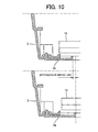
- Fig. 10 shows a partial cross-sectionalviewsof26-inchand27-inchplasmadisplaypanel assemblies 1a and 1b which are mounted to a common cabinet 2 as flat display panels.
- the cabinets 2 to which the 26-inch and 27-inch plasma display panel assemblies 1a and 1b are mounted are the same.
- view area sizes of the panel assemblies 1a and 1b are different, the distance between the panel-side peripheral edges of the cabinet and the circumference of the view area of the panel assembly 1a is naturally different from that of 1b. Therefore, it is impossible to directly cover up to the circumference of the view area of each of the panel assemblies 1a and 1b with the panel-side peripheral edge of the common cabinet 2.
- a double structure configuration is employedwherein the panel-side peripheral edge of the common cabinet 2 is held in front of the circumference of the view area of the panel assemble 1a, 1b to provide a gap, and thereby accommodate the difference in gaps formed by different panel sizes, and then the gap is covered with a decorative laminate 3a, 3b called a bezel as shown in Fig. 11 that fits the size of each panel assembly.
- a pair of metal molds comprising a core metal mold and a cavity metal mold are needed. That is, as shown in a partial cross-sectional view of Fig. 12, an approximately rectangular molding groove 4a is formed on the core metal mold 4 at a position corresponding to the circumference of the view area of the plasma display panel 1a, 1b.
- the molding groove 4a is formed on an area with approximately trapezoidal cross-section composed of: a bottom 4b corresponding to an area opposite to the screen of the plasma display panels 1a, 1b; an approximately vertical surface 4c corresponding to the inward of the view area; and a tapered surface 4d corresponding to the outward of the view area.
- the cavity metal mold 5 has a convex portion 5a with approximately trapezoidal cross-section that is composed of: a bottom 5b of having the same shape as an approximately rectangular area surrounded by the molding groove 4a of the core metal mold; and an upwardly expanding tapered surface 5c formed around the bottom 5b.
- the approximately rectangular area surrounded by the molding groove 4a on the core metal mold 4 and the bottom 5b of the convex portion 5a of the cavity metal mold 5 are brought into contact with each other, and resin is injected into a cavity 6 formed by the molding groove 4a on the core metal mold 4, the outward surface 4f of the molding groove 4a, and the convex portion 5a, tapered surface 5c, and outward surface 5d of the cavity metal mold 5.
- metal molds for molding the bezels are used for large-sized plasma display panels such as 26-inch and 27-inch panels, and sizes of those metal molds are very large, a very large storage space is necessary to prepare metal molds for different-sized plasma display panel assemblies.
- Patent Document 1 in molding an electrical junction box, the junction box is divided into a cavity portion and a box body, and the cavity portion is first molded and then the molded cavity portion is inserted into the box body.
- the other metal mold can be used in common, and therefore it is possible to reduce the cost and number of metal molds as compared with a case where the cavity portion and box body are integrally molded.
- Patent Document 2 in a cavity metal mold and a core metal mold each having a fitting nest, a blocking lever is attached to the nest of the core metal mold that can be moved in and out of a molding concave portion. The blocking lever is moved in to block the injection of resin according to the molding shape. This eliminates the need for replacing the nest for molding and as a result the cost and number of metal molds can be reduced.
- Patent Document 3 different shape molding is enabled by providing a removable nest portion in some part of a metal mold and replacing only the next portion. This allows only a nest portion to be replaced without having to prepare a whole metal mold, and consequently the cost and number of metal molds can be reduced.
- Patent Document 4 resin is injected before finishing the clamping, and the gap between cavity and core molds is filled with the resin injected through a film-like gate without providing a runner.
- the gate is cut by the clamping before the resin is hardened at a convex portion provided on the border between product and gate.
- Patent Document 2 it is certainly possible to reduce the number of metal molds by providing a shielding lever and moving the same in and out of the molding concave portion.
- this configuration is applied to the molding of the cabinet or bezel, a parting line corresponding to a mounting seam of the nest is inevitably formed. Since the cabinet and bezel is positioned at the outside of a product and meets the eyes of consumers, this parting line damages the appearance quality and therefore it is difficult to apply this configuration.
- the configuration of the abovementioned Japanese Patent 1996-132481 is a technology to prevent a weld line and a gate trace from being formed, and therefore is unable to solve the problem of increased number of metal molds described above.
- the present invention discloses resin molding metal molds and a resin molding method for flat display panel cabinets that resolves the problems with resin molding metal molds used for molding a cabinet to be mounted to the view area of different sized flat display panels, specifically the problem of double structure formed by a cabinet and a bezel and the problem of requiring various types of metal mold to mold different-sized bezels. Further, the present invention uses a common core metal mold for different sized cabinets and thereby reduce the number of metal molds. In addition, the present invention eliminates the need for the double structure wherein a cabinet and a bezel are mounted.
- a plasma display television whose cabinet molded by resin molding metal molds is mounted to the view area of a plasma display panel as a flat display panel, wherein:
- a cabinet for a plasma display panel of the first size is molded by using a combination of the core metal mold and the first cavity metal mold and injecting resin into a cavity formed by the first and second molding grooves on the core metal, a surface between these molding grooves, a surface outward of the second molding groove, while the tapered surface and outward upper surface of the convex portion on the first cavity metal mold, and a cabinet for a plasma display panel of the second size is molded by injecting resin into a cavity formed by the second molding groove on the core metal mold and an outward surface thereof and the tapered surface and an outward upper surface of the convex portion of the second cavity meta mold, with the first molding groove being covered by the bottom surface of the convex portion.
- the number of metal molds can be reduced by using a common core metal mold for plasma display panels of the first and second sizes, and also the double structure becomes unnecessary that is required when mounting a common cabinet to general-purpose plasma display panels of the first and second sizes, and includes a bezel to cover the gap between the view area of the plasma display panel and the cabinet, and as a result it is possible to provide a plasma display television manufactured with the resin molding metal molds that enables cost reduction, space saving, and high productivity.
- different -sized flat display panel cabinets are molded by combining one common core metal mold with an appropriate cavity metal mold according to the size of the cabinet, and when both metal molds are contacted, part of the concave portion is covered by the convex portion according to the size, and resin is injected into a cavity formed by the concave portion and the convex portion.
- the number of metal molds can be reduced by using a common core metal mold for different sized cabinet, and also the double structure becomes unnecessary that is required when mounting the common cabinet to different-sized flat panel displays and includes a bezel to cover the gap between the view area of the flat panel display and the cabinet, and thus it is possible to provide resin molding metal molds that enables cost reduction, space saving, and high productivity.
- resinmoldingmetal molds wherein:
- different -sized flat display panel cabinet is molded by combining a common core metal mold with a cavity metal mold according to the size, and injecting resin into a cavity formed by a molding groove on the core metal mold not covered by the undersurface of the convex portion on the cavity metal mold and the surface of the convex portion.
- the number of metal molds can be reduced by using a common core metal mold for different sized cabinet, and also the double structure becomes unnecessary that is required when mounting the common cabinet to different-sized flat panel displays and includes a bezel to cover the gap between the view area of the flat panel display and the cabinet, and thus it is possible to provide resin molding metal molds that enables cost reduction, space saving, and high productivity.
- resin molding metal molds wherein:
- a cabinet for different-sized flat display panels is molded by combining a common core metal mold with an appropriate cavity metal mold according to the size of the flat display panel, and when both metal molds are contacted, part of the concave portion is covered by the convex portion according to the size, and resin is injected into a cavity formed by the peripheral area of the bottom surface of the core metal mold not contacting the undersurface of the convex portion on the cavity metal mold, the side, and a side of the convex portion on the cavity metal mold.
- the number of metal molds can be reduced by using a common core metal mold for different sized cabinet, and also the double structure becomes unnecessary that is required when mounting the common cabinet to different-sized flat panel displays and includes a bezel to cover the gap between the view area of the flat panel display and the cabinet, and thus it is possible to provide resin molding metal molds that enables cost reduction, space saving, and high productivity.
- resin molding metal molds wherein:
- a cabinet for a 2 6-inch plasma display panel is molded by using a combination of the core metal mold and the first cavity metal mold and injecting resin into a cavity formed by the first and secondmolding grooves on the core metal, a surface between these molding grooves, a surface outward of the second molding groove, while the tapered surface and outward upper surface of the convex portion on the first cavity metal mold, and a cabinet for a 27-inchplasma display panel is molded by injecting resin into a cavity formed by the secondmolding groove on the coremetal mold and an outward surface thereof and the tapered surface and an outward upper surface of the convex portion of the second cavity meta mold, with the first molding groove being covered by the bottom surface of the convex portion.
- the number of metal molds can be reduced by using a common core metal mold for 26-inch and 27-inch plasma displaypanels, and also the double structure becomes unnecessary that is required when mounting a common cabinet to general-purpose plasma display panels of the first and second sizes, and includes a bezel to cover the gap between the view area of the plasma display panel and the cabinet, and
- a 26-inch plasma display panel cabinet is molded by covering part of the concave portion by the convex portion when both molds contact with each other, and injecting resin into a cavity formed by a peripheral area of the bottom surface of the concave portion of the core metal mold not contacting the under surface of the convex portion of the cavity metal mold, the tapered surface, an outward upper surface of the convex portion, the tapered surface of the convex portion of the cavity metal mold, and an outward upper surface of the convex portion, while a 27-inch plasma display panel cabinet is molded by covering part of a surface of the concave portion, which is one size larger than for a 26-inch plasma display panel when, by the convex portion when both metal molds are contacted, and injecting resin into a cavity formed by a peripheral area of the bottom surface of the core metal mold not contacting the undersurface of the convex portion of the cavity metal mold, the tapered surface, an outward upper surface of the concave portion, the tape
- the number of metal molds can be reduced by using a common core metal mold for 26-inch and 27-inch plasma displaypanels, and also the double structure becomes unnecessary that is required when mounting a common cabinet to 26-inch and 27-inch general-purpose plasma display panels, and includes a bezel to cover the gap between the view area of the plasma display panel and the cabinet, and as a result it is possible to provide a plasma display television manufactured with the resin molding metal molds that enables cost reduction, space saving, and high productivity.
- a resin molding method for a cabinet to be mounted to the view area of a flat display panel wherein:
- Fig. 1 shows a bloc diagram to explain a basic configuration of a plasma display television using a plasma display panel as a flat display panel of the present invention.
- a plasma display television 11 includes a controller 11b to control the operation of the plasma display television. Further included with the plasma display television 11 is a tuner 11d that extracts a television broadcast signal for a selectedchannel fromtelevisionbroadcast signals received by an antenna (not shown), and outputs the extracted signal.
- An image processing unit 11f displays on a plasma display panel 11e, images based on the television broadcast signal outputted from the tuner 11d.
- An audio processing unit 11h outputs from a speaker 11g audio based on the television broadcast signals outputted from the tuner 11d.
- a remote control signal receiving unit 11a receives a control command transmitted from a remote control 11c.
- the controller 11b controls the ON/OFF power of the system, changing of channels, audio control for volume, and similar controls according to a control command received by the remote control signal receiving unit 11a.
- a power supply circuit (not shown).
- the input to this power supply circuit is a commercial power source (for example, 100V AC).
- the plasma display panels 11e are supplied from a panel manufacturer as a 26-inch or 27-inch general-purpose plasma display panel assemblies 11e1, 11e2. These 26-inch and 27-inch general purpose plasma panel assemblies 11e1 and 11e2 are mounted to cabinet 13a and 13b respectively. These cabinets 13a and 13b have claw portions 13a1 and 13b1 respectively. Each claws has different shapes from each other so as to fit the different-sized view area, as shown in Figs. 2 and 3. Accordingly no gap is formed between plasma display panel and cabinet, so there is no need of adoption the conventional double structure including a bazel.
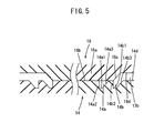
- the cabinet 13a and 13b are molded with metal molds configured as shown in Fig. 4 and 5, respectively. That is, a metal mold for molding the cabinet 13a for the 26-inch plasma display panel 11e1 is composed of a core metal mold 14 and a cavity metal mold 15.
- the core metal mold 14 has two different molding grooves, with a first approximately rectangular molding groove 14a formed at a position corresponding to first view area circumference of the 26-inch sized (first size) plasma display panel 11e1.
- a second approximately rectangular molding groove 14b is formed at a position corresponding to a second view area circumference, which is one size larger than the first view area circumference, of the 27-inch sized plasma display panel 11e2.
- the first molding groove 14a and the secondmolding groove 14b are formed on an area with approximately trapezoidal cross-section that is formed by the bottom surfaces 14a1, 14b1 corresponding to the areas opposite to the screen of a plasma display panel, and approximately vertical surfaces 14a2, 14b2 corresponding to the inward of the view area; and expanding tapered surfaces 14a3, 14b3 corresponding to the outward of the view area.
- the first cavity metal mold 15 has a convex portion 15a with approximately trapezoidal cross-section that is composedof anundersurface 15b of the same shape as an approximate rectangle surrounded by the first molding groove 14a on the core metal mold 14 and an upward expanding tapered surface 15c formed around the undersurface 15b.
- the metal mold for molding the cabinet 13b for the 27-inch plasma display panel 11e2 is composed of a core metal mold 14 and second cavity metal mold 16. That is, the core metal mold 14 is shared between the 26-inch and 27-inch plasma display panels.
- the second cavity metal mold 16 has a convex portion 16a with approximately trapezoidal cross-section that is composed of an undersurface 16b of the same shape as an approximate rectangle surrounded by the secondmolding groove 14b on the core metal mold 14 and an upward expanding tapered surface 16c formed around the undersurface 16b.
- the approximately rectangular surface surrounded by the first molding groove 14a on the core metal mold 14 and the undersurface 15b of the convex portion 15a on the first cavity metal mold 15 are contacted with each other.
- a cavity is formed by the first molding groove 14a on the core metal mold, the secondmolding groove 14b, the surface 14cbetween these two grooves, the outward surface 14d of the second molding groove 14b, and the tapered surface 15c of the convex portion 15a on the first cavity metal mold and outward upper surface 15d thereof.
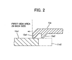
- the cabinet 13a molded as described above has the two claw portions 13a1 and 13a2 corresponding to the first molding groove 14a and second molding groove 14b respectively, as shown in Fig. 2.
- the claw portion 13a1 located on the edge faces the view area circumference of the 26-inch plasma display panel 11e1 when mounted.
- the conventional double structure, including a bezel is not necessary and the required peripheral positions on the plasma display panel 11e1 are completely covered with only the cabinet 13a.
- the other claw portion 13a2 is located opposite to the view area circumference of the 27-inch plasma display panel described later, and is not necessary for mounting the 26-inch plasma display panel 11e1, but has no problem since this claw portion 13a2 is located within the cabinet 13a hidden from the view.
- the approximately rectangular surface surrounded by the second molding groove 14b on the core metal mold 14 and the undersurface 16b of the convex portion 16a on the second cavity metal mold 16 are contacted with each other.
- the first molding groove 14a is covered at the underside of the convex portion 16a, and a cavity 17b is formed by the second molding 14b and the outward surface 14d thereof, and the tapered surface 16c of the convex portion on the second cavity metal mold 16 and the outward surface 16d thereof.
- the cabinet 13b molded as described above has no claw portion 13a1 for the 26-inch plasma display panel as shown in Fig. 3, since the first molding groove 14a on the core metal mold 14 is covered at the undersurface of the convex portion on the second cavity metal mold 16 and resin will not flow therein, resulting in only the claw portion 13a2 corresponding to the second molding groove 14b being formed.
- the claw portion 13a2 located on the edge faces the view area circumference of the 27-inch plasma display panel 11e2 when mounted.
- the conventional double structure including a bezel is not necessary and the required peripheral positions of the plasma display panel 11e2 are completely covered with only the cabinet 13b.
- the cabinets 13a and 13b to be mounted on the view area of the 26-inch and 27-inch general-purpose plasma display panels can be molded individually. This can be achieved by combining, as appropriate, the core metal mold 14 and one of the two different cavity metal molds 15 and 16, which correspond to the 26-inch and 27-inch plasmadisplaypanels, and covering the unnecessary first molding groove on the core metal mold 14 by the cavity metal mold 14 when molding the 27-inch cabinet 13b.
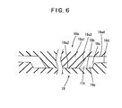
- a concave portion 18a on a core metal mold 18 is composed of an approximately rectangular bottom surface 18b surrounding an area corresponding to the view area circumference of the 27-inch plasma display panel 11e2 and the outward thick portion of the cabinet, and a upward tapered surface 18c formed around the bottom surface 18b.
- the cavity metal mold includes a third cavity metal mold 19a corresponding to the 26-inch plasma display panel 11e1, and a fourth cavity metal mold 19b corresponding to the 27-inch plasma display panel 11e2.
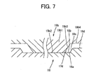
- the third cavity metal mold 19a has a convex portion 19a1 with approximately trapezoidal cross-section that is composed of an approximately rectangular undersurface 19a2 surrounding an area corresponding to the view area of the 26-inch plasma display panel 11e1 and an upward tapered surface 19a3 formed around the undersurface 19a2, while, in Fig. 7, the fourth cavity metal mold 19b has a convex portion 19b1 that is one size larger with approximately trapezoidal cross-section that is composed of an approximately rectangular undersurface 19b2 surrounding an area corresponding to the view area of the 27-inch plasma display panel 11e2 and a upward expanding tapered surface 19b3 formed around the undersurface 19b2.
- the approximately rectangular bottom surface 18b on the core metal mold 18 and the undersurface 19a2 of the convex portion 19a1 on the third cavity metal mold 19a are contacted with each other.
- a part of the concave portion 18a is covered by the convex portion 19b, and a cavity 17c is formed by; a peripheral area of the bottom surface 18b, which does not contact the undersurface 19a2; the tapered surface 18c; an outward upper surface 18d; the tapered surface 19a3; and an outward upper surface 19a4.
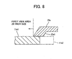
- the cabinet for a 26-inch plasma display panel as shown in Fig. 8 is molded.
- the cabinet 20a molded as described above has a claw portion 20a1.
- the claw portion 20a1 When the cabinet 20a is mounted the claw portion 20a1 is located at a position opposite to the view area circumference of the 26-inch plasma display panel 11e1, and the required peripheral positions of the plasma display panel 11e1 are completely covered by only the cabinet 20a, without the need of adopting the conventional double structure with a bezel. Since the peripheral side tapered surface of the claw portion 20a1 is located at the same position of the claw portion 20b1 (illustrated in Fig. 9) corresponding to the view area circumference of the 27-inch plasma display panel, the claw portion 20a1 is thicker than the claw portion 20b1, but it has no problem since it is located within the cabinet 20a and hidden from the eye.
- the approximately rectangular bottom surface 18b on the core metal mold and the undersurface 19bs of the convex portion 19ba on the fourth cavity metal mold 19b are contacted with each other.
- part of an area of the concave portion 18a is covered by the convex portion 19b1
- the covered area of the concave portion 18a is one size larger of the concave portion than in the case of the 26-inch plasma display panel is covered by the convex portion.
- a cavity 27d is formed by: a peripheral area of bottom surface 18b, which does not contact the undersurface 19b2; the tapered surface 18c; the outward upper surface 18d; the tapered surface 19b3; and the outward upper surface 19b4.
- the cabinet 20b for a 27-inch plasma display panel as shown in Fig. 9 is formed.
- the cabinet 20b molded as described above has a claw portion 20b1, as illustrated in Fig. 9.
- the claw portion 20b1 is located at an area opposite to the view area circumference of the plasma display panel 11e2, and the required peripheral positions of the plasma display panel 11e2 is completely covered by only the cabinet 20b, without the need of adopting the conventional double structure with a bezel.
- this embodiment is different from the first embodiment in that the size difference between 26-inch and 27-inch plasma display panels is accommodated by changing the size of an area where part of the concave portion is covered by the convex portion and thereby changing the thickness of the claw portion of the cabinet, thereby changing the thickness of the claw portion of the cabinet.
- both embodiment are substantially similar in that two different cavity metal molds corresponding to the sizes of 26-inch and 27-inch plasma display panels are prepared. That two different cavity metal mold are used by combining one of these metal molds with one core metal mold as appropriate. When the core and cavity metal molds are contacted with each other, part of the concave portion is covered by the convex portion according to the size of a plasma display panel. Resin is injected into a cavity formed by the concave portion and the convex portion to mold the cabinet to be mounted to the view area of a 26-inch or 27-inch general-purpose plasma display.
- this embodiment uses the same core metal mold for two different-sized (26-inchand27-inch) plasma display panels.
- This reduces the number of metal mold as compared with the prior art, and eliminates the need for the conventional double structure wherein a bezel is mounted to cover the gap between view area of the plasma display panel and the cabinet, which is required for a common cabinet to different-sized (26-inch and 27-inch) general-purpose plasma display panels. Consequently, it is possible to provide metal molds for resin molding whereby cost reduction, space saving, and productivity improvement can be achieved.
- a plasma display panel is described as an example of the flat display panel, but the present invention is not limited thereto and applicable to other flat display panels including an LCD and an organic EL.
- the vertical cross-section or horizontal cross-section of the concave portion and the convex portion (i.e., the cabinet to be molded) on the core metal mold and the cavity metal mold is only an example and can be changed as appropriate. The point is that it is sufficient to be able to form a cavity whereby a cabinet can be molded that fits the size of a flat display panel to which the cabinet is mounted.
- panel sizes used in the embodiments are 26-inch and 27-inch, these sizes are only examples and other sizes are possible. However, sizes must be adj acent to each other, such as a case that sizes are consecutive in a sequence, so that a common cabinet can be used.
- Panel sizes that allow molding with a common core metal mold are not limited to two sizes, and three or more sizes are possible. In such a case, a concave portion must be formed according to each additional size.
- each embodiment is configured to eliminate the double structure with a bezel, it is possible to leave this double structure with a bezel and use a common cabinet to apply the molding with each metal mold to a different bezel according to the size of a display panel. This eliminates the advantage of making the double structure with a bezel unnecessary, but at least the conventional advantage of reducing the number of metal molds in bezel molding can be obtained.
- each embodiment can be provided as not only a plasma television and metal molds for resin molding but also a resin molding method.
Landscapes
- Engineering & Computer Science (AREA)
- Multimedia (AREA)
- Signal Processing (AREA)
- Manufacturing & Machinery (AREA)
- Mechanical Engineering (AREA)
- Moulds For Moulding Plastics Or The Like (AREA)
- Devices For Indicating Variable Information By Combining Individual Elements (AREA)
- Injection Moulding Of Plastics Or The Like (AREA)
Abstract
Description
- The present invention relates to a resin molding metal mold and resin molding method for molding a cabinet to be mounted at the view area of a flat display panel, and a plasma display television provided with the cabinet.
- Televisions that display broadcast pictures to be watched by audiences have been widely used at home for a long time as major media for watching entertainment programs, movies, news, etc. However, Cathode Ray Tune (CRT)-based televisions which have been the mainstream for a long time have problems with depth, weight, and/or power consumption, and therefore increasing their screen sizes was about to reach a limit.
- Meanwhile, with the improvement in semiconductor technologies, new display devices such as plasma displays and Liquid Crystal Displays (LCDs) have been developed in recent years that are different from CRTs . Since these display devices are thinner as compared with conventional CRTs, they are often generically called flat display panels.
- The flat display panels for televisions have achieved reduced cost and increased size due to technological improvements and volume efficiency, and, coupled with replacement demand associated with the digitalization of television broadcast as well as housing conditions in Japan with restricted spaces, the market for flat display panels is rapidly expanding, taking over the conventional CRTs.
- When manufacturing televisions using these flat display panels, some manufacturers fabricate such televisions by using panel assemblies acquired from a panel manufacturer and adding their own control processing technology and the like to the panel assemblies. These general-purpose panel assemblies have various-sized view areas, and TV manufactures typically fabricate televisions by using different components according to different-sized panel assemblies.
- However, for different panel assemblies with approximate view areas sizes, for example, the same cabinets are often used as common cabinets to which these panel assemblies are mounted, for cost reduction. Fig. 10 shows a partial cross-sectionalviewsof26-inchand27-
inchplasmadisplaypanel assemblies common cabinet 2 as flat display panels. - In Fig. 10, the
cabinets 2 to which the 26-inch and 27-inch plasmadisplay panel assemblies panel assemblies panel assembly 1a is naturally different from that of 1b. Therefore, it is impossible to directly cover up to the circumference of the view area of each of thepanel assemblies common cabinet 2. Accordingly, a double structure configuration is employedwherein the panel-side peripheral edge of thecommon cabinet 2 is held in front of the circumference of the view area of the panel assemble 1a, 1b to provide a gap, and thereby accommodate the difference in gaps formed by different panel sizes, and then the gap is covered with adecorative laminate - To mold the
bezels rectangular molding groove 4a is formed on thecore metal mold 4 at a position corresponding to the circumference of the view area of theplasma display panel molding groove 4a is formed on an area with approximately trapezoidal cross-section composed of: abottom 4b corresponding to an area opposite to the screen of theplasma display panels vertical surface 4c corresponding to the inward of the view area; and atapered surface 4d corresponding to the outward of the view area. On the other hand, thecavity metal mold 5 has aconvex portion 5a with approximately trapezoidal cross-section that is composed of: abottom 5b of having the same shape as an approximately rectangular area surrounded by themolding groove 4a of the core metal mold; and an upwardly expandingtapered surface 5c formed around thebottom 5b. - To form the
bezel molding groove 4a on thecore metal mold 4 and thebottom 5b of theconvex portion 5a of thecavity metal mold 5 are brought into contact with each other, and resin is injected into acavity 6 formed by themolding groove 4a on thecore metal mold 4, theoutward surface 4f of themolding groove 4a, and theconvex portion 5a,tapered surface 5c, and outwardsurface 5d of thecavity metal mold 5. - As described above, since the distance to the gap to be covered by the bezel is different between the 26-inch and 27-inch plasma
display panel assemblies core metal mold 4, and the position of theconvex portion 5a of thecavity metal mold 5. As a result it is necessary to prepare four types ofmetal molds - That is, many types of metal mold are required and the cost increases substantially.
- Also, since metal molds for molding the bezels are used for large-sized plasma display panels such as 26-inch and 27-inch panels, and sizes of those metal molds are very large, a very large storage space is necessary to prepare metal molds for different-sized plasma display panel assemblies.
- Furthermore, it is also necessary to replace metal molds according to panel assembly sizes, and this mold change work consumes a great deal of time.
- On the other hand, for reducing the number or cost of metal molds used for resin molding, the following technology is disclosed.
- That is, according to
Japanese Patent Laid-Open No. 2001-298831 - According to
Japanese Utility Patent Laid-Open No. 1993-16256 - According to
Japanese Patent Laid-Open No. 1993-278081 - Also, the following prior art is disclosed that enables a plastic television cabinet to be molded without a weld line or gate trace.
- That is, according to
Japanese Patent Laid-Open No. 1996-132481 - However, in the configuration of the abovementioned
Japanese Patent Laid-Open No. 2001-298831 - When mounting different-sized plasma display panels to the cabinet as described above, the double structure composed of a cabinet and a bezel and the common use of a cabinet are alreadyproposed. The problem is that many differ ent metal molds are required in order to mold different-sized bezels. Therefore, this problem cannot be solved by the technology disclosed in the abovementioned Patent Document 1.
- In the configuration of
Patent Document 2, it is certainly possible to reduce the number of metal molds by providing a shielding lever and moving the same in and out of the molding concave portion. However, if this configuration is applied to the molding of the cabinet or bezel, a parting line corresponding to a mounting seam of the nest is inevitably formed. Since the cabinet and bezel is positioned at the outside of a product and meets the eyes of consumers, this parting line damages the appearance quality and therefore it is difficult to apply this configuration. - When applying the configuration in the abovementioned
Japanese Patent Laid-Open No. 1993-278081 - The configuration of the abovementioned
Japanese Patent 1996-132481 - The present invention discloses resin molding metal molds and a resin molding method for flat display panel cabinets that resolves the problems with resin molding metal molds used for molding a cabinet to be mounted to the view area of different sized flat display panels, specifically the problem of double structure formed by a cabinet and a bezel and the problem of requiring various types of metal mold to mold different-sized bezels. Further, the present invention uses a common core metal mold for different sized cabinets and thereby reduce the number of metal molds. In addition, the present invention eliminates the need for the double structure wherein a cabinet and a bezel are mounted.
- According to one embodiment of the present invention, there is provided a plasma display television whose cabinet molded by resin molding metal molds is mounted to the view area of a plasma display panel as a flat display panel, wherein:
- the plasma display panel is a general-purpose plasma display panel of one of a first size or a second size that is slightly larger than the first size;
- the metal molds include a core metal mold and cavity metal mold used in pairs;
- the core metal mold has two different molding grooves: an approximately rectangular first molding groove located at a position corresponding to a first view area circumference of the plasma display panel of the first size, and an approximately rectangular second molding groove that is one size larger than the first view area circumference and located at a position corresponding to a second view area circumference of the plasma display panel of the second size;
- the first molding groove and the second molding groove are formed on an area with approximately trapezoidal cross-section composed of a bottom surface corresponding to a position opposite to the screen of a plasma display panel, an approximately vertical surface corresponding to an inward side of the view area, and an expanding tapered surface corresponding to an outward side of the view area;
- the cavity metal mold has two different cavity metal molds including a first cavity metal mold corresponding to a first size of the plasma display panel, and a second cavity metal mold corresponding to a second size of the plasma display panel;
- the fist cavity metal mold has a convex portion with approximately trapezoidal cross-section which is made up of an undersurface having the same shape as an approximate rectangle surrounded by the first molding groove on the core metal mold, and an upwardly expanding tapered surface formed around the undersurface;
- the second cavity metal mold has a convex portion with approximately trapezoidal cross-section which is made up of an undersurface having the same shape as an approximate rectangle surrounded by the second molding groove on the core metal mold, and an upwardly expanding tapered surface formed around the undersurface;
- a cabinet for a plasma display panel of the first size is molded by making an approximately rectangular surface surrounded by the first molding groove on the core metal mold and an undersurface of the convex portion on the first cavity metal mold relatively contact each other, and injecting resin into a cavity formed by the first molding groove and the second molding groove on the core metal mold, a surface between these two molding grooves, an outward surface of the second molding groove, a tapered surface of the convex portion on the first cavity metal mold, and an outward upper surface thereof;
- a cabinet for the plasma display panel of the second size is molded by contacting an approximately rectangular surface surrounded by the second molding groove on the core metal mold and an undersurface of the convex portion on the second cavity metal mold, covering the first molding groove by an undersurface of the convex portion, and injecting resin into a cavity formed by the second molding groove on the core metal mold and a surface outward thereof, and a tapered surface of the convex portion of the second cavity metal mold and an upward upper surface thereof;
- one of the two cavity metal molds is combined with a common core metal mold as appropriate, and cabinets for two general-purpose plasma display panels of the first and seconds sizes respectively are individually molded;
- the number of metal mold can be reduced by using a common core metal mold for general-purpose plasma display panels of the first and second sizes; and
- the need for the double structure is eliminated that is required to cover the gap between the view area of the plasma display panel and the cabinet when mounting a general-purpose plasma display of the first size or the second sizes to a common cabinet.
- In the configuration as described above, a cabinet for a plasma display panel of the first size is molded by using a combination of the core metal mold and the first cavity metal mold and injecting resin into a cavity formed by the first and second molding grooves on the core metal, a surface between these molding grooves, a surface outward of the second molding groove, while the tapered surface and outward upper surface of the convex portion on the first cavity metal mold, and a cabinet for a plasma display panel of the second size is molded by injecting resin into a cavity formed by the second molding groove on the core metal mold and an outward surface thereof and the tapered surface and an outward upper surface of the convex portion of the second cavity meta mold, with the first molding groove being covered by the bottom surface of the convex portion.
- Accordingly, the number of metal molds can be reduced by using a common core metal mold for plasma display panels of the first and second sizes, and also the double structure becomes unnecessary that is required when mounting a common cabinet to general-purpose plasma display panels of the first and second sizes, and includes a bezel to cover the gap between the view area of the plasma display panel and the cabinet, and as a result it is possible to provide a plasma display television manufactured with the resin molding metal molds that enables cost reduction, space saving, and high productivity.
- Another embodiment of the present invention, there are provide resin molding metal molds for molding a cabinet to be mounted to the view area of a flat panel display, wherein:
- the flat display panel has at least two different sizes;
- the metal molds comprise a core metal mold and a cavity metal mold;
- the core metal mold is a common metal mold having a concave portion that forms a resin molding cavity corresponding to all sizes of the cabinet for flat display panels,
- while the cavity metal mold is a metal mold that has a convex portion forming a resin molding cavity corresponding to each size of the cabinet for a flat display panel, and that has the number of metal molds corresponding to the number of sizes of the cabinet; and
- one of the cavity metal molds is combined with the single common core metal mold according to the size of the flat display panel, and when the both metal molds are relatively contacted, part of the concave portion is covered by the convex portion according to the size, and resin is injected into a cavity formed by the concave portion and the convex portion to mold the cabinet according to the size of a flat display panel.
- In the configuration as described above, different -sized flat display panel cabinets are molded by combining one common core metal mold with an appropriate cavity metal mold according to the size of the cabinet, and when both metal molds are contacted, part of the concave portion is covered by the convex portion according to the size, and resin is injected into a cavity formed by the concave portion and the convex portion.
- Accordingly, the number of metal molds can be reduced by using a common core metal mold for different sized cabinet, and also the double structure becomes unnecessary that is required when mounting the common cabinet to different-sized flat panel displays and includes a bezel to cover the gap between the view area of the flat panel display and the cabinet, and thus it is possible to provide resin molding metal molds that enables cost reduction, space saving, and high productivity.
- According to another embodiment of the present invention, there are provided resinmoldingmetal molds, wherein:
- said concave portion of said core metal mold has a plurality of approximately rectangular molding grooves according to the number of sizes, at positions corresponding to the view area circumference of the flat display, and said each molding groove is composed of a bottom surface corresponding to a position opposite the screen of the flat display panel and both side surfaces thereof, and a side surface formed around the undersurface;
- said convex portion of said each cavity metal mold corresponding to each size of said flat display panel is composed of an approximately rectangular undersurface having the same shape as an approximate rectangle surrounded by each molding groove corresponding to said each size of the flat display panel, and a side surface formed around the undersurface;
- to mold a cabinet, said common core metal mold is combined with said cavity metal mold according to the size of said flat display panel, contacting said approximately rectangular bottom surface of said core metal mold and an undersurface of said convex portion of said cavity metal mold, covering part of said concave portion by said convex portion according to the size of said flat display panel, and injecting resin into a cavity formed by a peripheral area of the bottom surface of said core metal mold not contacting the undersurface of said convex portion of said cavitymetal mold, the side, and a side of said convex portion on said cavity metal mold;
- the number of metal molds is reduced by using a common core metal mold for different-sized flat panel displays; and
- at the same time, the double structure is made unnecessary which is required when mounting a common cabinet to different-sized plasma display panels and which includes a bezel to cover the gap between the view area of said plasma display panel and said cabinet.
- In the configuration as described above, different -sized flat display panel cabinet is molded by combining a common core metal mold with a cavity metal mold according to the size, and injecting resin into a cavity formed by a molding groove on the core metal mold not covered by the undersurface of the convex portion on the cavity metal mold and the surface of the convex portion.
- Accordingly, the number of metal molds can be reduced by using a common core metal mold for different sized cabinet, and also the double structure becomes unnecessary that is required when mounting the common cabinet to different-sized flat panel displays and includes a bezel to cover the gap between the view area of the flat panel display and the cabinet, and thus it is possible to provide resin molding metal molds that enables cost reduction, space saving, and high productivity.
- According to another embodiment of the present invention, there is provided resin molding metal molds, wherein:
- a concave portion of said core metal mold is composed of an approximately rectangular bottom surface surrounding an area corresponding to the largest-sized view area circumference of a flat displaypanel and the outward thereof by cabinet thickness, and a side surface formed around the bottom surface;
- a convex portion of said each cavity metal mold corresponding to each size of the flat display panel is composed of an approximately rectangular undersurface surrounding an area corresponding to the view area circumference of said each sized flat panel display, and a side surface formed around the undersurface;
- to mold a cabinet, said one common core metal mold is combined with said cavity metal mold as appropriate according to the size of the flat display panel, said approximately rectangular bottom surface of said core metal mold and a undersurface of said convex portion of said cavity metal mold are contacted with each other, part of said concave portion is covered by said convex portion according to the size, and resin is injected into a cavity formed by a peripheral area of the undersurface of the convex portion of the cavity metal mold not contacting the undersurface, the side surface, and the side surface of said convex portion of the cavity metal mold;
- the number of metal molds is reduced by using a common core metal mold for different-sized flat display panels; and
- the double structure is made unnecessary which is required when mounting a common cabinet to different-sized general-purpose plasma display panels and which includes a bezel to cover the gap between the view area of said plasma display panel and said cabinet.
- In the configuration as described above, a cabinet for different-sized flat display panels is molded by combining a common core metal mold with an appropriate cavity metal mold according to the size of the flat display panel, and when both metal molds are contacted, part of the concave portion is covered by the convex portion according to the size, and resin is injected into a cavity formed by the peripheral area of the bottom surface of the core metal mold not contacting the undersurface of the convex portion on the cavity metal mold, the side, and a side of the convex portion on the cavity metal mold.
- Accordingly, the number of metal molds can be reduced by using a common core metal mold for different sized cabinet, and also the double structure becomes unnecessary that is required when mounting the common cabinet to different-sized flat panel displays and includes a bezel to cover the gap between the view area of the flat panel display and the cabinet, and thus it is possible to provide resin molding metal molds that enables cost reduction, space saving, and high productivity.
- According to another embodiment of the present invention, there are provided resin molding metal molds wherein:
- the flat display panel is a 26-inch or 27-inch general-purpose plasma display panel;
- the core metal mold has two different molding grooves: an approximately rectangular first molding groove located at a position corresponding to a first view area circumference of a 26-inch plasma display panel, and an approximately rectangular second molding groove that is one size larger than the first view area circumference and located at a position corresponding to a second view area circumference of a 27-inch plasma display panel;
- the first molding groove and the second molding groove are formed on an area with approximately trapezoidal cross-section composed of a bottom surface corresponding to a position opposite to the screen of a plasma display panel, an approximately vertical surface corresponding to the inward side of the view area, and an expanding tapered surface corresponding to outward side of the view area;
- the cavity metal mold includes a first cavity metal mold for a 26-inch plasma display panel, and a second cavity metal mold for a 27-inch plasma display panel;
- the cavity metal mold has a convex portion with approximately trapezoidal cross-section which is composed of an undersurface having the same shape as an approximate rectangle surrounded by the first molding groove of the core metal mold, and an upwardly expanding tapered surface formed around the
- undersurface;
- the first cavity metal mold has a convex portion with approximately trapezoidal cross-section that is composed of an undersurface having the same shape as an approximate rectangle surrounded by the first molding groove of the core metal mold;
- the second cavity metal mold has a convex portion with approximately trapezoidal cross-section which is composed of an undersurface having the same shape as an approximate rectangle surrounded by the second molding groove of the core metal mold, and an upwardly expanding tapered surface formed around the undersurface;
- a cabinet for a 26-inch plasma display panel is molded by contacting an approximately rectangular surface surrounded by the first molding groove on the core metal mold and a undersurface of the convex portion on the first cavity metal mold, and injecting resin into a cavity formed by the first molding groove and the second molding groove of the core metal mold, a surface between these two molding grooves, an outward surface of the second molding groove, the tapered surface of the convex portion on the first cavity metal mold, and an outward upper surface thereof;
- a cabinet for the 27-inch plasma display panel is molded by contacting an approximately rectangular surface surrounded by the second molding groove of the core metal mold and an undersurface of the convex portion of the second cavity metal mold, covering the first molding groove by the undersurface of the convex portion, and injecting resin into a cavity formed by the second molding groove of the core metal mold and a surface outward thereof, and a tapered surface of the convex portion on the second cavity metal mold and an upward upper surface thereof;
- one of the two cavity metal molds is combined with a common core metal mold as appropriate, and cabinets for 26-inch and 27-inch general-purpose plasma display panels respectively are individually molded;
- the number of metal mold can be reduced by using a common core metal mold for 26-inch and 27-inch general-purpose plasma display panels; and
- the need for the double structure is eliminated that is required to cover the gap between the view area of the plasma display panel and the cabinet when mounting a 26-inch or 27-inch general-purpose plasma display to a common cabinet.
- In the configuration as described above, a cabinet for a 2 6-inch plasma display panel is molded by using a combination of the core metal mold and the first cavity metal mold and injecting resin into a cavity formed by the first and secondmolding grooves on the core metal, a surface between these molding grooves, a surface outward of the second molding groove, while the tapered surface and outward upper surface of the convex portion on the first cavity metal mold, and a cabinet for a 27-inchplasma display panel is molded by injecting resin into a cavity formed by the secondmolding groove on the coremetal mold and an outward surface thereof and the tapered surface and an outward upper surface of the convex portion of the second cavity meta mold, with the first molding groove being covered by the bottom surface of the convex portion.
- Accordingly, the number of metal molds can be reduced by using a common core metal mold for 26-inch and 27-inch plasma displaypanels, and also the double structure becomes unnecessary that is required when mounting a common cabinet to general-purpose plasma display panels of the first and second sizes, and includes a bezel to cover the gap between the view area of the plasma display panel and the cabinet, and
- According to another embodiment of the present invention, there are provided the resin molding metal molds wherein:
- the flat panel display is a 26-inch or 27-inch general-purpose plasma display panel;
- a concave portion of the core metal mold is composed of an approximately rectangular bottom surface surrounding the view area circumference of a 27-inch plasma display panel and an area corresponding to the thickness outward of the cabinet, and an upwardly expanding tapered surface formed around the bottom surface;
- the cavity metal mold includes a third cavity metal mold for a 26-inch plasma display panel, and a fourth cavity metal mold for a 27-inch plasma display panel;
- the third cavity metal mold has a convex portion with approximately trapezoidal cross-section that is composed of an approximately rectangular undersurface surrounding an area corresponding to the view area of a 26-inch plasma display panel and an upwardly expanding tapered surface formed around the undersurface;
- the fourth cavity metal mold has a convex portion that is one size larger with approximately trapezoidal cross-section that is composed of an approximately rectangular undersurface surrounding an area corresponding to the view area circumference of a 27-inch plasma display panel and an upwardly expanding tapered surface formed around the undersurface;
- a 26-inch plasma display panel cabinet is molded by contacting an approximately rectangular bottom surface of the core metal mold and an undersurface of the concave portion of the third cavity metal mold, covering part of the concave portion by the convex portion, and injecting resin into a cavity formed by a peripheral area of the bottom surface of the concave portion of the core metal mold not contacting the undersurface of the convex portion of the cavity metal mold, the tapered surface, an outward upper surface of the concave portion, the tapered surface of the convex portion of the cavity metal mold, and an outward upper surface of the convex portion;
- a 27-inch plasma display panel cabinet is molded by contacting an approximately rectangular bottom surface of the core metal mold and an undersurface of the convex portion of the fourth cavity metal mold, covering part of an surface of the concave portion, which is one size larger than for a 26-inch plasma display panel, by the convex portion, and injecting resin into a cavity formed by a peripheral area of the bottom surface of the concave portion of the core metal mold not contacting the undersurface of the convex portion of the cavity metal mold, the tapered surface, an outward upper surface of the concave portion, the tapered surface of the convex portion of the cavity metal mold, and an outward upper surface of the convex portion;
- cabinets to be mounted to the view area of 26-inch and 27-inch general-purpose plasma display panels are individually molded by combining a common core metal mold with one of two cavity metal molds as appropriate;
- the number of metal molds is reduced by using one common core metal mold for 26-inch and 27-inch plasma display panels; and
- at the same time, the double structure is made unnecessary that is required when mounting a common cabinet to 26-inch and 27-inch general-purpose plasma display panels and includes a bezel to cover the gap between the view area of the plasma display panel and the cabinet.
- In the configuration as described above, a 26-inch plasma display panel cabinet is molded by covering part of the concave portion by the convex portion when both molds contact with each other, and injecting resin into a cavity formed by a peripheral area of the bottom surface of the concave portion of the core metal mold not contacting the under surface of the convex portion of the cavity metal mold, the tapered surface, an outward upper surface of the convex portion, the tapered surface of the convex portion of the cavity metal mold, and an outward upper surface of the convex portion, while a 27-inch plasma display panel cabinet is molded by covering part of a surface of the concave portion, which is one size larger than for a 26-inch plasma display panel when, by the convex portion when both metal molds are contacted, and injecting resin into a cavity formed by a peripheral area of the bottom surface of the core metal mold not contacting the undersurface of the convex portion of the cavity metal mold, the tapered surface, an outward upper surface of the concave portion, the tapered surface of the convex portion of the cavity metal mold, and an outward upper surface of the convex portion.
- Accordingly, the number of metal molds can be reduced by using a common core metal mold for 26-inch and 27-inch plasma displaypanels, and also the double structure becomes unnecessary that is required when mounting a common cabinet to 26-inch and 27-inch general-purpose plasma display panels, and includes a bezel to cover the gap between the view area of the plasma display panel and the cabinet, and as a result it is possible to provide a plasma display television manufactured with the resin molding metal molds that enables cost reduction, space saving, and high productivity.
- According to another embodiment of the present invention, there is provided a resin molding method for a cabinet to be mounted to the view area of a flat display panel, wherein:
- the flat panel display has at least two different sizes;
- a core metal mold out of a pair of mating metal molds is a common metal mold having a concave surface that forms a cavity for resin molding accommodating all the sizes of the cabinet for a flat display panel;
- the other cavity metal mold out of the pair of mating metal molds is a metal mold that has surfaces of a convex portion forming a cavity for resin molding for each size of the cabinet for the flat display panel, and the same number of the cavity metal molds as the number of sizes of a flat display panel are prepared; and
- the single common core metal mold and one of the cavity metal molds combined according to the size of the flat display panel are used as appropriate, and when the both metal molds are contacted with each other, part of the concave portion is covered by the convex portion according to the size of the flat display panel, and resin is injected into a cavity formed by the concave portion and convex portion to mold the cabinet fit for the flat display panel.
- This provides a resin molding method by which similar advantages can be obtained.
- Embodiments of the present invention will be described in detail based on the following figures, wherein:
- Fig. 1 is a bloc diagram to explain embodiment 1 of the present invention;
- Fig. 2 is a partial cross-section view to explain embodiment 1 of the present invention;
- Fig. 3 is a partial cross-section view to explain embodiment 1 of the present invention;
- Fig. 4 is a partial cross-section view to explain embodiment 1 of the present invention;
- Fig. 5 is a partial cross-section view to explain embodiment 1 of the present invention;
- Fig. 6 is a partial cross-section view to explain
embodiment 2 of the present invention; - Fig. 7 is a partial cross-section view to explain
embodiment 2 of the present invention; - Fig. 8 is a partial cross-section view to explain
embodiment 2 of the present invention; - Fig. 9 is a partial cross-section view to explain
embodiment 2 of the present invention; - Fig. 10 is a partial cross-section view to explain a prior art;
- Fig. 11 is perspective view to explain the prior art; and
- Fig. 12 is a partial cross-section view to explain the prior art.
- While the invention has been particularly shown and described with respect to preferred embodiments thereof, it shouldbe understood by those skilled in the art that the foregoing and other changes in form and detail may be made therein without departing from the spirit and scope of the invention as defined in the appended claims.
- Fig. 1 shows a bloc diagram to explain a basic configuration of a plasma display television using a plasma display panel as a flat display panel of the present invention.
- As illustrated in Fig. 1, a
plasma display television 11 includes acontroller 11b to control the operation of the plasma display television. Further included with theplasma display television 11 is atuner 11d that extracts a television broadcast signal for a selectedchannel fromtelevisionbroadcast signals received by an antenna (not shown), and outputs the extracted signal. Animage processing unit 11f displays on aplasma display panel 11e, images based on the television broadcast signal outputted from thetuner 11d. Anaudio processing unit 11h outputs from aspeaker 11g audio based on the television broadcast signals outputted from thetuner 11d. A remote controlsignal receiving unit 11a receives a control command transmitted from aremote control 11c. - The
controller 11b controls the ON/OFF power of the system, changing of channels, audio control for volume, and similar controls according to a control command received by the remote controlsignal receiving unit 11a. To each unit, such as the remote controlsignal receiving unit 11a, thecontroller 11b, thetuner 11d, theplasma display panel 11e, theimage processing unit 11f, and thevoice processing unit 11h, in theplasma display television 11, an operating current is supplied from a power supply circuit (not shown). The input to this power supply circuit is a commercial power source (for example, 100V AC). - The
plasma display panels 11e are supplied from a panel manufacturer as a 26-inch or 27-inch general-purpose plasma display panel assemblies 11e1, 11e2. These 26-inch and 27-inch general purpose plasma panel assemblies 11e1 and 11e2 are mounted tocabinet cabinets - Amethodofmolding the
cabinets - The
cabinet cabinet 13a for the 26-inch plasma display panel 11e1 is composed of acore metal mold 14 and acavity metal mold 15. Thecore metal mold 14 has two different molding grooves, with a first approximatelyrectangular molding groove 14a formed at a position corresponding to first view area circumference of the 26-inch sized (first size) plasma display panel 11e1. A second approximatelyrectangular molding groove 14b is formed at a position corresponding to a second view area circumference, which is one size larger than the first view area circumference, of the 27-inch sized plasma display panel 11e2. - The
first molding groove 14a and thesecondmolding groove 14b are formed on an area with approximately trapezoidal cross-section that is formed by the bottom surfaces 14a1, 14b1 corresponding to the areas opposite to the screen of a plasma display panel, and approximately vertical surfaces 14a2, 14b2 corresponding to the inward of the view area; and expanding tapered surfaces 14a3, 14b3 corresponding to the outward of the view area. - The first
cavity metal mold 15 has aconvex portion 15a with approximately trapezoidal cross-section that iscomposedof anundersurface 15b of the same shape as an approximate rectangle surrounded by thefirst molding groove 14a on thecore metal mold 14 and an upward expanding taperedsurface 15c formed around theundersurface 15b. - On the other hand, the metal mold for molding the
cabinet 13b for the 27-inch plasma display panel 11e2 is composed of acore metal mold 14 and secondcavity metal mold 16. That is, thecore metal mold 14 is shared between the 26-inch and 27-inch plasma display panels. The secondcavity metal mold 16 has aconvex portion 16a with approximately trapezoidal cross-section that is composed of anundersurface 16b of the same shape as an approximate rectangle surrounded by thesecondmolding groove 14b on thecore metal mold 14 and an upward expanding tapered surface 16c formed around theundersurface 16b. - To mold the
cabinet 13a for the 26-inch plasma display panel 11e1, the approximately rectangular surface surrounded by thefirst molding groove 14a on thecore metal mold 14 and theundersurface 15b of theconvex portion 15a on the firstcavity metal mold 15 are contacted with each other. As a result, a cavity is formed by thefirst molding groove 14a on the core metal mold, thesecondmolding groove 14b, the surface 14cbetween these two grooves, theoutward surface 14d of thesecond molding groove 14b, and the taperedsurface 15c of theconvex portion 15a on the first cavity metal mold and outwardupper surface 15d thereof. By injecting resin into thiscavity 17a, thecabinet 13a for the 26-inch plasma display panel 11e1 is molded. - The
cabinet 13a molded as described above has the two claw portions 13a1 and 13a2 corresponding to thefirst molding groove 14a andsecond molding groove 14b respectively, as shown in Fig. 2. The claw portion 13a1 located on the edge faces the view area circumference of the 26-inch plasma display panel 11e1 when mounted. The conventional double structure, including a bezel is not necessary and the required peripheral positions on the plasma display panel 11e1 are completely covered with only thecabinet 13a. The other claw portion 13a2 is located opposite to the view area circumference of the 27-inch plasma display panel described later, and is not necessary for mounting the 26-inch plasma display panel 11e1, but has no problem since this claw portion 13a2 is located within thecabinet 13a hidden from the view. - To mold the
cabinet 13b for the 27-inch plasma display panel, the approximately rectangular surface surrounded by thesecond molding groove 14b on thecore metal mold 14 and theundersurface 16b of theconvex portion 16a on the secondcavity metal mold 16 are contacted with each other. As a result, thefirst molding groove 14a is covered at the underside of theconvex portion 16a, and acavity 17b is formed by thesecond molding 14b and theoutward surface 14d thereof, and the tapered surface 16c of the convex portion on the secondcavity metal mold 16 and the outward surface 16d thereof. By injecting resin into thiscavity 17b, thecabinet 13b for the 27-inch plasma display panel 11e2 is molded. - The
cabinet 13b molded as described above has no claw portion 13a1 for the 26-inch plasma display panel as shown in Fig. 3, since thefirst molding groove 14a on thecore metal mold 14 is covered at the undersurface of the convex portion on the secondcavity metal mold 16 and resin will not flow therein, resulting in only the claw portion 13a2 corresponding to thesecond molding groove 14b being formed. The claw portion 13a2 located on the edge faces the view area circumference of the 27-inch plasma display panel 11e2 when mounted. The conventional double structure including a bezel is not necessary and the required peripheral positions of the plasma display panel 11e2 are completely covered with only thecabinet 13b. - As described above, in this embodiment, the
cabinets core metal mold 14 and one of the two differentcavity metal molds core metal mold 14 by thecavity metal mold 14 when molding the 27-inch cabinet 13b. - Accordingly, by sharing one
core metal mold 14 in molding the different sized (26-inch and 27-inch) cabinets, the number of metal molds is reduced as compared with the prior art, and also the conventional double structure becomes unnecessary that includes a bezel to cover the gap between the view area of a plasma display panel and the cabinet, which is required to mount the common cabinet for 26-inch and 27-inch general-purpose plasma display panels. As a result, it is possible to provide metal molds for resin molding that achieves cost saving, space saving, and improved productivity. - Next, another embodiment is described that is substantially similar as the above-mentioned embodiment in that one core metal mold and one of two different cavity metal molds corresponding to 26-inch and 27-inch plasma display panels are combined as appropriate, and cabinets to be mounted to the view area sides of the two different-sized general-purpose plasma displays are individually molded, but the shapes of the core metal mold and cavity metal mold are different.
- Only the different configuration from the previous embodiment is described, the description of the common configuration being omitted.
- As shown in Fig. 6, a
concave portion 18a on acore metal mold 18 is composed of an approximately rectangularbottom surface 18b surrounding an area corresponding to the view area circumference of the 27-inch plasma display panel 11e2 and the outward thick portion of the cabinet, and a upward taperedsurface 18c formed around thebottom surface 18b. - On the other hand, the cavity metal mold includes a third
cavity metal mold 19a corresponding to the 26-inch plasma display panel 11e1, and a fourthcavity metal mold 19b corresponding to the 27-inch plasma display panel 11e2. - The third
cavity metal mold 19a has a convex portion 19a1 with approximately trapezoidal cross-section that is composed of an approximately rectangular undersurface 19a2 surrounding an area corresponding to the view area of the 26-inch plasma display panel 11e1 and an upward tapered surface 19a3 formed around the undersurface 19a2, while, in Fig. 7, the fourthcavity metal mold 19b has a convex portion 19b1 that is one size larger with approximately trapezoidal cross-section that is composed of an approximately rectangular undersurface 19b2 surrounding an area corresponding to the view area of the 27-inch plasma display panel 11e2 and a upward expanding tapered surface 19b3 formed around the undersurface 19b2. - As shown in Fig. 6, to mold the cabinet for a 26-inch plasma display panel, the approximately rectangular
bottom surface 18b on thecore metal mold 18 and the undersurface 19a2 of the convex portion 19a1 on the thirdcavity metal mold 19a are contacted with each other. As a result, a part of theconcave portion 18a is covered by theconvex portion 19b, and acavity 17c is formed by; a peripheral area of thebottom surface 18b, which does not contact the undersurface 19a2; the taperedsurface 18c; an outwardupper surface 18d; the tapered surface 19a3; and an outward upper surface 19a4. By injecting resin into thiscavity 17c, the cabinet for a 26-inch plasma display panel as shown in Fig. 8 is molded. - The
cabinet 20a molded as described above has a claw portion 20a1. When thecabinet 20a is mounted the claw portion 20a1 is located at a position opposite to the view area circumference of the 26-inch plasma display panel 11e1, and the required peripheral positions of the plasma display panel 11e1 are completely covered by only thecabinet 20a, without the need of adopting the conventional double structure with a bezel. Since the peripheral side tapered surface of the claw portion 20a1 is located at the same position of the claw portion 20b1 (illustrated in Fig. 9) corresponding to the view area circumference of the 27-inch plasma display panel, the claw portion 20a1 is thicker than the claw portion 20b1, but it has no problem since it is located within thecabinet 20a and hidden from the eye. - On the other hand, to mold the cabinet 20b (illustrated in Fig. 9) for a 27-inch plasma display panel, as shown in Fig. 7, the approximately rectangular
bottom surface 18b on the core metal mold and the undersurface 19bs of the convex portion 19ba on the fourthcavity metal mold 19b are contacted with each other. As a result, part of an area of theconcave portion 18a is covered by the convex portion 19b1, and the covered area of theconcave portion 18a is one size larger of the concave portion than in the case of the 26-inch plasma display panel is covered by the convex portion. A cavity 27d is formed by: a peripheral area ofbottom surface 18b, which does not contact the undersurface 19b2; the taperedsurface 18c; the outwardupper surface 18d; the tapered surface 19b3; and the outward upper surface 19b4. By injecting resin into this cavity, the cabinet 20b for a 27-inch plasma display panel as shown in Fig. 9 is formed. - The cabinet 20b molded as described above has a claw portion 20b1, as illustrated in Fig. 9. When the cabinet 20b is mounted the claw portion 20b1 is located at an area opposite to the view area circumference of the plasma display panel 11e2, and the required peripheral positions of the plasma display panel 11e2 is completely covered by only the cabinet 20b, without the need of adopting the conventional double structure with a bezel.
- As described above, this embodiment is different from the first embodiment in that the size difference between 26-inch and 27-inch plasma display panels is accommodated by changing the size of an area where part of the concave portion is covered by the convex portion and thereby changing the thickness of the claw portion of the cabinet, thereby changing the thickness of the claw portion of the cabinet. However, both embodiment are substantially similar in that two different cavity metal molds corresponding to the sizes of 26-inch and 27-inch plasma display panels are prepared. That two different cavity metal mold are used by combining one of these metal molds with one core metal mold as appropriate. When the core and cavity metal molds are contacted with each other, part of the concave portion is covered by the convex portion according to the size of a plasma display panel. Resin is injected into a cavity formed by the concave portion and the convex portion to mold the cabinet to be mounted to the view area of a 26-inch or 27-inch general-purpose plasma display.
- Accordingly, this embodiment uses the same core metal mold for two different-sized (26-inchand27-inch) plasma display panels. This reduces the number of metal mold as compared with the prior art, and eliminates the need for the conventional double structure wherein a bezel is mounted to cover the gap between view area of the plasma display panel and the cabinet, which is required for a common cabinet to different-sized (26-inch and 27-inch) general-purpose plasma display panels. Consequently, it is possible to provide metal molds for resin molding whereby cost reduction, space saving, and productivity improvement can be achieved.
- The present invention is not limited to the configuration of each embodiment, and can be modified to apply to the following non-limiting exemplary configurations listed below.
- 1. In each embodiment, a plasma display panel is described as an example of the flat display panel, but the present invention is not limited thereto and applicable to other flat display panels including an LCD and an organic EL.
- 2. In each embodiment, the vertical cross-section or horizontal cross-section of the concave portion and the convex portion (i.e., the cabinet to be molded) on the core metal mold and the cavity metal mold is only an example and can be changed as appropriate. The point is that it is sufficient to be able to form a cavity whereby a cabinet can be molded that fits the size of a flat display panel to which the cabinet is mounted.
- 3. Although the panel sizes used in the embodiments are 26-inch and 27-inch, these sizes are only examples and other sizes are possible. However, sizes must be adj acent to each other, such as a case that sizes are consecutive in a sequence, so that a common cabinet can be used.
- 4. Panel sizes that allow molding with a common core metal mold are not limited to two sizes, and three or more sizes are possible. In such a case, a concave portion must be formed according to each additional size.
- 5. Although each embodiment is configured to eliminate the double structure with a bezel, it is possible to leave this double structure with a bezel and use a common cabinet to apply the molding with each metal mold to a different bezel according to the size of a display panel. This eliminates the advantage of making the double structure with a bezel unnecessary, but at least the conventional advantage of reducing the number of metal molds in bezel molding can be obtained.
- 6. The configuration described in each embodiment can be provided as not only a plasma television and metal molds for resin molding but also a resin molding method.
- It should be understood by those skilled in the art that various modifications, combinations, sub-combinations and alterations may occur depending on design requirements and other factors insofar as they are within the scope of the appended claims or the equivalents thereof.
Claims (7)
- A plasma display television whose cabinet molded by resin molding metal molds is mounted to the view area of a plasma display panel as a flat display panel,
wherein:the plasma display panel is a general-purpose plasma display panel of one of a first size or a second size that is slightly larger than the first size;the metal molds include a core metal mold and cavity metal mold used in pairs;the core metal mold has two different molding grooves: an approximately rectangular first molding groove located at a position corresponding to a first view area circumference of the plasma display panel of the first size, and an approximately rectangular second molding groove that is one size larger than the first view area circumference and located at a position corresponding to a second view area circumference of the plasma display panel of the second size;the first molding groove and the second molding groove are formed on an area with approximately trapezoidal cross-section composed of a bottom surface corresponding to a position opposite to the screen of a plasma display panel, an approximately vertical surface corresponding to an inward side of the view area, and an expanding tapered surface corresponding to an outward side of the view area;the cavity metal mold has two different cavity metal molds including a first cavity metal mold corresponding to a first size of the plasma display panel, and a second cavity metal mold corresponding to a second size of the plasma display panel;the fist cavity metal mold has a convex portion with approximately trapezoidal cross-section which is made up of an undersurface having the same shape as an approximate rectangle surrounded by the first molding groove on the core metal mold, and an upwardly expanding tapered surface formed around the undersurface;the second cavity metal mold has a convex portion with approximately trapezoidal cross-section which is made up of an undersurface having the same shape as an approximate rectangle surrounded by the second molding groove on the core metal mold, and an upwardly expanding tapered surface formed around the undersurface;a cabinet for a plasma display panel of the first size is molded by making an approximately rectangular surface surrounded by the first molding groove on the core metal mold and an undersurface of the convex portion on the first cavity metal mold relatively contact each other, and injecting resin into a cavity formed by the first molding groove and the second molding groove on the core metal mold, a surface between these two molding grooves, an outward surface of the second molding groove, a tapered surface of the convex portion on the first cavity metal mold, and an outward upper surface thereof;a cabinet for the plasma display panel of the second size is molded by contacting an approximately rectangular surface surrounded by the second molding groove on the core metal mold and an undersurface of the convex portion on the second cavity metal mold, covering the first molding groove by an undersurface of the convex portion, and injecting resin into a cavity formed by the second molding groove on the core metal mold and a surface outward thereof, and a tapered surface of the convex portion of the second cavity metal mold and an upward upper surface thereof;one of the two cavity metal molds is combined with a common core metal mold as appropriate, and cabinets for two general-purpose plasma display panels of the first and seconds sizes respectively are individually molded;the number of metal mold can be reduced by using a common core metal mold for general-purpose plasma display panels of the first and second sizes; andthe need for the double structure is eliminated that is required to cover the gap between the view area of the plasma display panel and the cabinet when mounting a general-purpose plasma display of the first size or the second sizes to a common cabinet. - Resin molding metal molds for molding a cabinet to be mounted to the view area of a flat panel display,
wherein:the flat display panel has at least two different sizes;the metal molds comprise a core metal mold and a cavity metal mold;the core metal mold is a common metal mold having a concave portion that forms a resin molding cavity corresponding to all sizes of the cabinet for flat display panels,while the cavity metal mold is a metal mold that has a convex portion forming a resin molding cavity corresponding to each size of the cabinet for a flat display panel, and that has the number of metal molds corresponding to the number of sizes of the cabinet; andone of the cavity metal molds is combined with the single common core metal mold according to the size of the flat display panel, and when the both metal molds are relatively contacted, part of the concave portion is covered by the convex portion according to the size, and resin is injected into a cavity formed by the concave portion and the convex portion to mold the cabinet according to the size of a flat display panel. - The resin molding metal molds as defined in claim 2,
wherein:said concave portion of said core metal mold has a plurality of approximately rectangular molding grooves according to the number of sizes, at positions corresponding to the view area circumference of the flat display, and said each molding groove is composed of a bottom surface corresponding to a position opposite the screen of the flat display panel and both side surfaces thereof, and a side surface formed around the undersurface;said convex portion of said each cavity metal mold corresponding to each size of said flat display panel is composed of an approximately rectangular undersurface having the same shape as an approximate rectangle surrounded by each molding groove corresponding to said each size of the flat display panel, and a side surface formed around the undersurface;to mold a cabinet, said common core metal mold is combined with said cavity metal mold according to the size of said flat displaypanel, contacting said approximately rectangular bottom surface of said core metal mold and an undersurface of said convex portion of said cavity metal mold, covering part of said concave portion by said convex portion according to the size of said flat display panel, and injecting resin into a cavity formed by a peripheral area of the bottom surface of said core metal mold not contacting the undersurface of said convex portion of said cavitymetal mold, the side, and a side of said convex portion on said cavity metal mold;the number of metal molds is reduced by using a common core metal mold for different-sized flat panel displays; andat the same time, the double structure is made unnecessary which is required when mounting a common cabinet to different-sizedplasma displaypanels and which includes a bezel to cover the gap between the view area of said plasma display panel and said cabinet. - The resin molding metal molds as defined in claim 2,
wherein:a concave portion of said core metal mold is composed of an approximately rectangular bottom surface surrounding an area corresponding to the largest-sized view area circumference of a flat display panel and the outward thereof by cabinet thickness, and a side surface formed around the bottom surface;a convex portion of said each cavity metal mold corresponding to each size of the flat display panel is composed of an approximately rectangular undersurface surrounding an area corresponding to the view area circumference of said each sized flat panel display, and a side surface formed around the undersurface;to mold a cabinet, said one common core metal mold is combined with said cavity metal mold as appropriate according to the size of the flat display panel, said approximately rectangular bottom surface of said core metal mold and a undersurface of said convex portion of said cavity metal mold are contacted with each other, part of said concave portion is covered by said convex portion according to the size, and resin is injected into a cavity formed by a peripheral area of the undersurface of the convex portion of the cavity metal mold not contacting the undersurface, the side surface, and the side surface of said convex portion of the cavity metal mold;the number of metal molds is reduced by using a common core metal mold for different-sized flat display panels; andthe double structure is made unnecessary which is required when mounting a common cabinet to different-sized general-purpose plasma display panels and which includes a bezel to cover the gap between the view area of said plasma display panel and said cabinet. - The resin molding metal molds as defined in claim 3,
wherein:the flat display panel is a 26-inch or 27-inch general-purpose plasma display panel;the core metal mold has two different molding grooves: an approximately rectangular first molding groove located at a position corresponding to a first view area circumference of a 26-inch plasma display panel, and an approximately rectangular second molding groove that is one size larger than the first view area circumference and located at a position corresponding to a second view area circumference of a 27-inch plasma display panel;the first molding groove and the second molding groove are formed on an area with approximately trapezoidal cross-section composed of a bottom surface corresponding to a position opposite to the screen of a plasma display panel, an approximately vertical surface corresponding to the inward side of the view area, and an expanding tapered surface corresponding to outward side of the view area;the cavity metal mold includes a first cavity metal mold for a 26-inch plasma display panel, and a second cavity metal mold for a 27-inch plasma display panel;the cavity metal mold has a convex portion with approximately trapezoidal cross-section which is composed of an undersurface having the same shape as an approximate rectangle surrounded by the first molding groove of the core metal mold, and an upwardly expanding tapered surface formed around the undersurface;the first cavity metal mold has a convex portion with approximately trapezoidal cross-section that is composed of an undersurface having the same shape as an approximate rectangle surrounded by the first molding groove of the core metal mold;the second cavity metal mold has a convex portion with approximately trapezoidal cross-section which is composed of an undersurface having the same shape as an approximate rectangle surrounded by the second molding groove of the core metal mold, and an upwardly expanding tapered surface formed around the undersurface;a cabinet for a 26-inch plasma display panel is molded by contacting an approximately rectangular surface surrounded by the first molding groove on the core metal mold and a undersurface of the convex portion on the first cavity metal mold, and injecting resin into a cavity formed by the first molding groove and the second molding groove of the core metal mold, a surface between these two molding grooves, an outward surface of the second molding groove, the tapered surface of the convex portion on the first cavity metal mold, and an outward upper surface thereof;a cabinet for the 27-inch plasma display panel is molded by contacting an approximately rectangular surface surrounded by the second molding groove of the core metal mold and an undersurface of the convex portion of the second cavity metal mold, covering the first molding groove by the undersurface of the convex portion, and injecting resin into a cavity formed by the second molding groove of the core metal mold and a surface outward thereof, and a tapered surface of the convex portion on the second cavity metal mold and an upward upper surface thereof;one of the two cavity metal molds is combined with a common core metal mold as appropriate, and cabinets for 26-inch and 27-inch general-purpose plasma display panels respectively are individually molded;the number of metal mold can be reduced by using a common core metal mold for 26-inch and 27-inch general-purpose plasma display panels; andthe need for the double structure is eliminated that is required to cover the gap between the view area of the plasma display panel and the cabinet when mounting a 26-inch or 27-inch general-purpose plasma display to a common cabinet. - The resin molding metal molds as defined in claim 4,
wherein:the flat panel display is a 26-inch or 27-inch general-purpose plasma display panel;a concave portion of the core metal mold is composed of an approximately rectangular bottom surface surrounding the view area circumference of a 27-inch plasma display panel and an area corresponding to the thickness outward of the cabinet, and an upwardly expanding tapered surface formed around the bottom surface;the cavity metal mold includes a third cavity metal mold for a 26-inch plasma display panel, and a fourth cavity metal mold for a 27-inch plasma display panel;the third cavity metal mold has a convex portion with approximately trapezoidal cross-section that is composed of an approximately rectangular undersurface surrounding an area corresponding to the view area of a 26-inch plasma display panel and an upwardly expanding tapered surface formed around the undersurface;the fourth cavity metal mold has a convex portion that is one size larger with approximately trapezoidal cross-section that is composed of an approximately rectangular undersurface surrounding an area corresponding to the view area circumference of a 27-inch plasma display panel and an upwardly expanding tapered surface formed around the undersurface;a 26-inch plasma display panel cabinet is molded by contacting an approximately rectangular bottom surface of the core metal mold and an undersurface of the concave portion of the third cavity metal mold, covering part of the concave portion by the convex portion, and injecting resin into a cavity formed by a peripheral area of the bottom surface of the concave portion of the core metal mold not contacting the undersurface of the convex portion of the cavity metal mold, the tapered surface, an outward upper surface of the concave portion, the tapered surface of the convex portion of the cavity metal mold, and an outward upper surface of the convex portion;a 27-inch plasma display panel cabinet is molded by contacting an approximately rectangular bottom surface of the core metal mold and an undersurface of the convex portion of the fourth cavity metal mold, covering part of an surface of the concave portion, which is one size larger than for a 26-inch plasma display panel, by the convex portion, and injecting resin into a cavity formed by a peripheral area of the bottom surface of the concave portion of the core metal mold not contacting the undersurface of the convex portion of the cavity metal mold, the tapered surface, an outward upper surface of the concave portion, the tapered surface of the convex portion of the cavity metal mold, and an outward upper surface of the convex portion;cabinets to be mounted to the view area of 26-inch and 27-inch general-purpose plasma display panels are individually molded by combining a common core metal mold with one of two cavity metal molds as appropriate;the number of metal molds is reduced by using one common core metal mold for 26-inch and 27-inch plasma display panels; andat the same time, the double structure is made unnecessary that is required when mounting a common cabinet to 26-inch and 27-inch general-purpose plasma display panels and includes a bezel to cover the gap between the view area of the plasma display panel and the cabinet. - A resin molding method for a cabinet to be mounted to the view area of a flat display panel,
wherein:the flat panel display has at least two different sizes;a core metal mold out of a pair of mating metal molds is a common metal mold having a concave surface that forms a cavity for resin molding accommodating all the sizes of the cabinet for a flat display panel;the other cavity metal mold out of the pair of mating metal molds is a metal mold that has surfaces of a convex portion forming a cavity for resin molding for each size of the cabinet for the flat display panel, and the same number of the cavity metal molds as the number of sizes of a flat display panel are prepared; andthe single common core metal mold and one of the cavity metal molds combined according to the size of the flat display panel are used as appropriate, and when the both metal molds are contacted with each other, part of the concave portion is covered by the convex portion according to the size of the flat display panel, and resin is injected into a cavity formed by the concave portion and convex portion to mold the cabinet fit for the flat display panel.
Applications Claiming Priority (1)
| Application Number | Priority Date | Filing Date | Title |
|---|---|---|---|
| JP2005308479A JP4069395B2 (en) | 2005-10-24 | 2005-10-24 | Mold for resin molding and resin molding method |
Publications (2)
| Publication Number | Publication Date |
|---|---|
| EP1777054A1 true EP1777054A1 (en) | 2007-04-25 |
| EP1777054B1 EP1777054B1 (en) | 2010-01-06 |
Family
ID=37694332
Family Applications (1)
| Application Number | Title | Priority Date | Filing Date |
|---|---|---|---|
| EP06021985A Not-in-force EP1777054B1 (en) | 2005-10-24 | 2006-10-19 | Mold for injection moulding, injection molding method for flat display panel cabinet, and plasma display television |
Country Status (4)
| Country | Link |
|---|---|
| US (1) | US20070093931A1 (en) |
| EP (1) | EP1777054B1 (en) |
| JP (1) | JP4069395B2 (en) |
| DE (1) | DE602006011553D1 (en) |
Cited By (1)
| Publication number | Priority date | Publication date | Assignee | Title |
|---|---|---|---|---|
| EP1998564A2 (en) | 2007-05-30 | 2008-12-03 | Funai Electric Co., Ltd. | Cabinet |
Families Citing this family (2)
| Publication number | Priority date | Publication date | Assignee | Title |
|---|---|---|---|---|
| WO2014069456A1 (en) * | 2012-10-30 | 2014-05-08 | シャープ株式会社 | Display device |
| CN206870218U (en) * | 2017-07-10 | 2018-01-12 | 晋城富泰华精密电子有限公司 | Enter minor structure |
Citations (8)
| Publication number | Priority date | Publication date | Assignee | Title |
|---|---|---|---|---|
| JPH0615685A (en) * | 1992-06-30 | 1994-01-25 | Japan Steel Works Ltd:The | Injection molding method and injection molding machine |
| DE19544736A1 (en) * | 1995-11-30 | 1997-06-05 | Metz Werke Gmbh & Co Kg | Housing for electronic device, such as multi-media computer, monitor |
| JP2001145046A (en) * | 1999-11-12 | 2001-05-25 | Matsushita Electric Ind Co Ltd | Video equipment cabinet |
| JP2001353756A (en) * | 2000-06-16 | 2001-12-25 | Matsushita Electric Ind Co Ltd | Frame forming equipment |
| US20020080297A1 (en) * | 2000-12-27 | 2002-06-27 | Ki-Hyub Sung | Display apparatus |
| WO2003066308A1 (en) * | 2002-02-06 | 2003-08-14 | B.M. Industria Bergamasca Mobili S.P.A. | Mould for tv chassis and tv frames |
| JP2004075756A (en) * | 2002-08-13 | 2004-03-11 | Mitsubishi Engineering Plastics Corp | Polybutylene terephthalate resin composition and molded article |
| US20050024552A1 (en) * | 2003-07-28 | 2005-02-03 | Benq Corporation | Liquid crystal display and manufacturing method thereof |
Family Cites Families (2)
| Publication number | Priority date | Publication date | Assignee | Title |
|---|---|---|---|---|
| DE4042499C2 (en) * | 1990-12-21 | 1995-05-04 | Marianne Wieser | Removable insert for mould |
| JP3367343B2 (en) * | 1996-07-22 | 2003-01-14 | 松下電器産業株式会社 | Cabinet device of projection television receiver, molding die and resin molding method |
-
2005
- 2005-10-24 JP JP2005308479A patent/JP4069395B2/en not_active Expired - Fee Related
-
2006
- 2006-10-19 US US11/583,191 patent/US20070093931A1/en not_active Abandoned
- 2006-10-19 DE DE602006011553T patent/DE602006011553D1/en active Active
- 2006-10-19 EP EP06021985A patent/EP1777054B1/en not_active Not-in-force
Patent Citations (8)
| Publication number | Priority date | Publication date | Assignee | Title |
|---|---|---|---|---|
| JPH0615685A (en) * | 1992-06-30 | 1994-01-25 | Japan Steel Works Ltd:The | Injection molding method and injection molding machine |
| DE19544736A1 (en) * | 1995-11-30 | 1997-06-05 | Metz Werke Gmbh & Co Kg | Housing for electronic device, such as multi-media computer, monitor |
| JP2001145046A (en) * | 1999-11-12 | 2001-05-25 | Matsushita Electric Ind Co Ltd | Video equipment cabinet |
| JP2001353756A (en) * | 2000-06-16 | 2001-12-25 | Matsushita Electric Ind Co Ltd | Frame forming equipment |
| US20020080297A1 (en) * | 2000-12-27 | 2002-06-27 | Ki-Hyub Sung | Display apparatus |
| WO2003066308A1 (en) * | 2002-02-06 | 2003-08-14 | B.M. Industria Bergamasca Mobili S.P.A. | Mould for tv chassis and tv frames |
| JP2004075756A (en) * | 2002-08-13 | 2004-03-11 | Mitsubishi Engineering Plastics Corp | Polybutylene terephthalate resin composition and molded article |
| US20050024552A1 (en) * | 2003-07-28 | 2005-02-03 | Benq Corporation | Liquid crystal display and manufacturing method thereof |
Cited By (3)
| Publication number | Priority date | Publication date | Assignee | Title |
|---|---|---|---|---|
| EP1998564A2 (en) | 2007-05-30 | 2008-12-03 | Funai Electric Co., Ltd. | Cabinet |
| EP1998564A3 (en) * | 2007-05-30 | 2009-09-02 | Funai Electric Co., Ltd. | Cabinet |
| US8366213B2 (en) | 2007-05-30 | 2013-02-05 | Funai Electric Co., Ltd. | Assembly structure of a cabinet and thin display device |
Also Published As
| Publication number | Publication date |
|---|---|
| DE602006011553D1 (en) | 2010-02-25 |
| JP4069395B2 (en) | 2008-04-02 |
| JP2007112089A (en) | 2007-05-10 |
| US20070093931A1 (en) | 2007-04-26 |
| EP1777054B1 (en) | 2010-01-06 |
Similar Documents
| Publication | Publication Date | Title |
|---|---|---|
| US12313937B2 (en) | Display apparatus comprising a side portion having an outer side surface that is entirely exposed to form an exterior side surface of the display apparatus | |
| JP5554870B1 (en) | Liquid crystal display device and display device | |
| US7405925B2 (en) | Display apparatus | |
| CN212161167U (en) | Display device and display screen | |
| EP1777054B1 (en) | Mold for injection moulding, injection molding method for flat display panel cabinet, and plasma display television | |
| US8820953B2 (en) | Backlight system | |
| US8469582B2 (en) | Back frame and backlight system | |
| US10310310B2 (en) | Display module and display device | |
| US8545038B2 (en) | Back frame of flat panel display device, backlight system, and flat liquid crystal display device | |
| US20130128499A1 (en) | Back Frame, Mold For Back Frame, Method For Manufacturing Back Frame, and Backlight System | |
| US20130128513A1 (en) | Mold for Back Frame and Bracing Piece, Method for Manufacturing Back Frame, and Backlight System | |
| US20130050283A1 (en) | Display device and electronic unit | |
| US20130128514A1 (en) | Mold for Back Frame and Bracing Piece, Method for Manufacturing Back Frame, and Backlight System | |
| JP4304515B2 (en) | Assembly structure, assembly method, and plasma television | |
| US20130128509A1 (en) | Flat Panel Display Device, Stereoscopic Display Device, and Plasma Display Device | |
| US11016323B2 (en) | Front bezel assembly structure for display apparatus, and display apparatus | |
| JP4823370B2 (en) | Electronics | |
| US8823895B2 (en) | Flat panel display device, stereoscopic display device, and plasma display device | |
| US20130128553A1 (en) | Back Frame, Backlight System, and Flat Liquid Crystal Display Device | |
| US8752999B2 (en) | Back frame of flat panel display device and backlight system | |
| US9036107B2 (en) | Flat panel display device, stereoscopic display device, plasma display device | |
| US20130128507A1 (en) | Back Frame, Method for Manufacturing Back Frame, and Backlight System | |
| CN105045343A (en) | Electronic equipment | |
| US20080284290A1 (en) | Television receiving set | |
| US20130128427A1 (en) | Back Frame of Flat Panel Display Device and Backlight System |
Legal Events
| Date | Code | Title | Description |
|---|---|---|---|
| PUAI | Public reference made under article 153(3) epc to a published international application that has entered the european phase |
Free format text: ORIGINAL CODE: 0009012 |
|
| AK | Designated contracting states |
Kind code of ref document: A1 Designated state(s): AT BE BG CH CY CZ DE DK EE ES FI FR GB GR HU IE IS IT LI LT LU LV MC NL PL PT RO SE SI SK TR |
|
| AX | Request for extension of the european patent |
Extension state: AL BA HR MK YU |
|
| 17P | Request for examination filed |
Effective date: 20070530 |
|
| 17Q | First examination report despatched |
Effective date: 20070628 |
|
| AKX | Designation fees paid |
Designated state(s): DE FR GB |
|
| GRAP | Despatch of communication of intention to grant a patent |
Free format text: ORIGINAL CODE: EPIDOSNIGR1 |
|
| GRAS | Grant fee paid |
Free format text: ORIGINAL CODE: EPIDOSNIGR3 |
|
| GRAA | (expected) grant |
Free format text: ORIGINAL CODE: 0009210 |
|
| AK | Designated contracting states |
Kind code of ref document: B1 Designated state(s): DE FR GB |
|
| REG | Reference to a national code |
Ref country code: GB Ref legal event code: FG4D |
|
| REF | Corresponds to: |
Ref document number: 602006011553 Country of ref document: DE Date of ref document: 20100225 Kind code of ref document: P |
|
| PLBE | No opposition filed within time limit |
Free format text: ORIGINAL CODE: 0009261 |
|
| STAA | Information on the status of an ep patent application or granted ep patent |
Free format text: STATUS: NO OPPOSITION FILED WITHIN TIME LIMIT |
|
| 26N | No opposition filed |
Effective date: 20101007 |
|
| PGFP | Annual fee paid to national office [announced via postgrant information from national office to epo] |
Ref country code: DE Payment date: 20141014 Year of fee payment: 9 Ref country code: FR Payment date: 20141008 Year of fee payment: 9 Ref country code: GB Payment date: 20141015 Year of fee payment: 9 |
|
| REG | Reference to a national code |
Ref country code: DE Ref legal event code: R119 Ref document number: 602006011553 Country of ref document: DE |
|
| GBPC | Gb: european patent ceased through non-payment of renewal fee |
Effective date: 20151019 |
|
| PG25 | Lapsed in a contracting state [announced via postgrant information from national office to epo] |
Ref country code: DE Free format text: LAPSE BECAUSE OF NON-PAYMENT OF DUE FEES Effective date: 20160503 Ref country code: GB Free format text: LAPSE BECAUSE OF NON-PAYMENT OF DUE FEES Effective date: 20151019 |
|
| REG | Reference to a national code |
Ref country code: FR Ref legal event code: ST Effective date: 20160630 |
|
| PG25 | Lapsed in a contracting state [announced via postgrant information from national office to epo] |
Ref country code: FR Free format text: LAPSE BECAUSE OF NON-PAYMENT OF DUE FEES Effective date: 20151102 |