EP1776993B1 - Diesel filter - Google Patents
Diesel filter Download PDFInfo
- Publication number
- EP1776993B1 EP1776993B1 EP06022075A EP06022075A EP1776993B1 EP 1776993 B1 EP1776993 B1 EP 1776993B1 EP 06022075 A EP06022075 A EP 06022075A EP 06022075 A EP06022075 A EP 06022075A EP 1776993 B1 EP1776993 B1 EP 1776993B1
- Authority
- EP
- European Patent Office
- Prior art keywords
- fuel
- case
- filter
- cap
- stepped portion
- Prior art date
- Legal status (The legal status is an assumption and is not a legal conclusion. Google has not performed a legal analysis and makes no representation as to the accuracy of the status listed.)
- Not-in-force
Links
- 239000000446 fuel Substances 0.000 claims description 178
- XLYOFNOQVPJJNP-UHFFFAOYSA-N water Substances O XLYOFNOQVPJJNP-UHFFFAOYSA-N 0.000 claims description 117
- 230000002093 peripheral effect Effects 0.000 claims description 21
- 239000003566 sealing material Substances 0.000 claims description 15
- 239000002184 metal Substances 0.000 claims description 8
- 230000000717 retained effect Effects 0.000 description 12
- 238000004519 manufacturing process Methods 0.000 description 9
- 238000002474 experimental method Methods 0.000 description 7
- 238000001914 filtration Methods 0.000 description 6
- 238000010586 diagram Methods 0.000 description 5
- 238000000889 atomisation Methods 0.000 description 4
- 238000002485 combustion reaction Methods 0.000 description 4
- 230000007613 environmental effect Effects 0.000 description 4
- 230000006835 compression Effects 0.000 description 3
- 238000007906 compression Methods 0.000 description 3
- 230000005484 gravity Effects 0.000 description 3
- 238000002347 injection Methods 0.000 description 3
- 239000007924 injection Substances 0.000 description 3
- 238000007789 sealing Methods 0.000 description 3
- 239000000853 adhesive Substances 0.000 description 2
- 230000001070 adhesive effect Effects 0.000 description 2
- 230000015572 biosynthetic process Effects 0.000 description 2
- 239000012530 fluid Substances 0.000 description 2
- 239000002828 fuel tank Substances 0.000 description 2
- JEIPFZHSYJVQDO-UHFFFAOYSA-N iron(III) oxide Inorganic materials O=[Fe]O[Fe]=O JEIPFZHSYJVQDO-UHFFFAOYSA-N 0.000 description 2
- 238000012423 maintenance Methods 0.000 description 2
- 239000007787 solid Substances 0.000 description 2
- 238000010276 construction Methods 0.000 description 1
- 230000008878 coupling Effects 0.000 description 1
- 238000010168 coupling process Methods 0.000 description 1
- 238000005859 coupling reaction Methods 0.000 description 1
- 239000000428 dust Substances 0.000 description 1
- 230000000694 effects Effects 0.000 description 1
- 230000002708 enhancing effect Effects 0.000 description 1
- 239000003502 gasoline Substances 0.000 description 1
- 239000011521 glass Substances 0.000 description 1
- 238000009434 installation Methods 0.000 description 1
- 239000007788 liquid Substances 0.000 description 1
- 239000000463 material Substances 0.000 description 1
- 239000007769 metal material Substances 0.000 description 1
- 239000002245 particle Substances 0.000 description 1
- 238000000926 separation method Methods 0.000 description 1
- 238000009692 water atomization Methods 0.000 description 1
- 238000004804 winding Methods 0.000 description 1
Images



Classifications
-
- B—PERFORMING OPERATIONS; TRANSPORTING
- B01—PHYSICAL OR CHEMICAL PROCESSES OR APPARATUS IN GENERAL
- B01D—SEPARATION
- B01D29/00—Filters with filtering elements stationary during filtration, e.g. pressure or suction filters, not covered by groups B01D24/00 - B01D27/00; Filtering elements therefor
- B01D29/01—Filters with filtering elements stationary during filtration, e.g. pressure or suction filters, not covered by groups B01D24/00 - B01D27/00; Filtering elements therefor with flat filtering elements
- B01D29/05—Filters with filtering elements stationary during filtration, e.g. pressure or suction filters, not covered by groups B01D24/00 - B01D27/00; Filtering elements therefor with flat filtering elements supported
- B01D29/07—Filters with filtering elements stationary during filtration, e.g. pressure or suction filters, not covered by groups B01D24/00 - B01D27/00; Filtering elements therefor with flat filtering elements supported with corrugated, folded or wound filtering sheets
- B01D29/073—Filters with filtering elements stationary during filtration, e.g. pressure or suction filters, not covered by groups B01D24/00 - B01D27/00; Filtering elements therefor with flat filtering elements supported with corrugated, folded or wound filtering sheets with wound filtering sheets
-
- B—PERFORMING OPERATIONS; TRANSPORTING
- B01—PHYSICAL OR CHEMICAL PROCESSES OR APPARATUS IN GENERAL
- B01D—SEPARATION
- B01D29/00—Filters with filtering elements stationary during filtration, e.g. pressure or suction filters, not covered by groups B01D24/00 - B01D27/00; Filtering elements therefor
- B01D29/01—Filters with filtering elements stationary during filtration, e.g. pressure or suction filters, not covered by groups B01D24/00 - B01D27/00; Filtering elements therefor with flat filtering elements
-
- B—PERFORMING OPERATIONS; TRANSPORTING
- B01—PHYSICAL OR CHEMICAL PROCESSES OR APPARATUS IN GENERAL
- B01D—SEPARATION
- B01D36/00—Filter circuits or combinations of filters with other separating devices
- B01D36/003—Filters in combination with devices for the removal of liquids
-
- F—MECHANICAL ENGINEERING; LIGHTING; HEATING; WEAPONS; BLASTING
- F02—COMBUSTION ENGINES; HOT-GAS OR COMBUSTION-PRODUCT ENGINE PLANTS
- F02M—SUPPLYING COMBUSTION ENGINES IN GENERAL WITH COMBUSTIBLE MIXTURES OR CONSTITUENTS THEREOF
- F02M37/00—Apparatus or systems for feeding liquid fuel from storage containers to carburettors or fuel-injection apparatus; Arrangements for purifying liquid fuel specially adapted for, or arranged on, internal-combustion engines
- F02M37/22—Arrangements for purifying liquid fuel specially adapted for, or arranged on, internal-combustion engines, e.g. arrangements in the feeding system
- F02M37/32—Arrangements for purifying liquid fuel specially adapted for, or arranged on, internal-combustion engines, e.g. arrangements in the feeding system characterised by filters or filter arrangements
- F02M37/42—Installation or removal of filters
-
- F—MECHANICAL ENGINEERING; LIGHTING; HEATING; WEAPONS; BLASTING
- F02—COMBUSTION ENGINES; HOT-GAS OR COMBUSTION-PRODUCT ENGINE PLANTS
- F02M—SUPPLYING COMBUSTION ENGINES IN GENERAL WITH COMBUSTIBLE MIXTURES OR CONSTITUENTS THEREOF
- F02M37/00—Apparatus or systems for feeding liquid fuel from storage containers to carburettors or fuel-injection apparatus; Arrangements for purifying liquid fuel specially adapted for, or arranged on, internal-combustion engines
- F02M37/22—Arrangements for purifying liquid fuel specially adapted for, or arranged on, internal-combustion engines, e.g. arrangements in the feeding system
- F02M37/24—Arrangements for purifying liquid fuel specially adapted for, or arranged on, internal-combustion engines, e.g. arrangements in the feeding system characterised by water separating means
- F02M37/26—Arrangements for purifying liquid fuel specially adapted for, or arranged on, internal-combustion engines, e.g. arrangements in the feeding system characterised by water separating means with water detection means
- F02M37/28—Arrangements for purifying liquid fuel specially adapted for, or arranged on, internal-combustion engines, e.g. arrangements in the feeding system characterised by water separating means with water detection means with means activated by the presence of water, e.g. alarms or means for automatic drainage
Definitions
- the invention relates to a diesel filter provided in a fuel supply system of a vehicle and the like, particularly to a diesel filter that improves water separation performance and/or reduces maintenance costs.
- Diesel engines have long been used as engines for vehicles and the like.
- a filter filters light oil in a fuel tank, and an injection pump compresses the filtered fuel to a high pressure, and an injector injects the fuel to a combustion chamber of the engine, whereby self-combustion takes place in the combustion chamber.
- fuel includes foreign matters, for example, water, dust, and solid undesirable materials such as rust. These foreign matters need to be removed because inclusion thereof results in reduced combustion efficiency and wear of the injector or the like.
- Diesel filters are, therefore, provided to deal with such problems. More specifically, water content in fuel is classified into dissolved water and free water. Dissolved water causes no negative effects, because it flows smoothly in fuel channels and is consumed together with fuel. Meanwhile, free water may cause some problems as follows. Free water appears in fuel when: rainwater intrudes into the fuel during fueling; water droplets formed by moisture in the air intrude into the fuel; or the water dissolved in the fuel is separated therefrom due to a decrease in fuel temperature. Such free water is large in specific gravity compared to light oil, so that it stagnates in the injection pump and the like, thus generating rust and stick. For this reason, free water particularly needs to be removed using a diesel filter.
- Diesel filters for automobile use are desired to have such structure.
- FIG. 8 shows a diesel filter related to the invention.
- a diesel filter 1 includes a cup-shaped case 2 forming an outer shell, and a cap 3 detachably attached to an upper opening end of the case 2.
- the cap 3 is provided with a fuel supply pipe 4, a fuel discharge pipe 5, and a hand pump 6. The supply and discharge of fuel are performed through the fuel supply pipe 4 and the fuel discharge pipe 5 respectively, and air is released from the fuel supply system by means of the hand pump 6.
- a filter member 11 Housed in the case 2 is a filter member 11 that includes an element 8 having a fuel passage 7 at the center thereof, and an upper holding member 9 and a lower holding member 10 for holding the upper and lower ends of the element 8.
- a water reservoir 12 is formed below the filter member 11.
- Fuel is introduced to the water reservoir 12 through the fuel supply pipe 4 and the fuel passage 7 as indicated by arrows (1), (2) and (3).
- the introduced fuel changes its direction by 180° in the water reservoir 12, and then moves upward.
- the fuel is filtered by passing through the element 8 and discharged from the fuel discharge pipe 5 as indicated by arrows (4), (5) and (6).
- water is separated from the fuel.
- the separated water has a larger specific gravity than the fuel, so that the water is retained in the water reservoir 12 (see Japanese Patent Application Publication No. JP-A-2003-172224 ).
- the amount of water retained in the water reservoir 12 becomes larger as the flow rate of fuel passing through the element 8 reduces.
- the experiment using the related art device shown in FIG 8 shows that the amount of water retained in the water reservoir 12 is not large when the flow rate of fuel is high, as indicated by, for example, the curve denoted by "CENTER FLOW" in the diagram of FIG. 7 .
- this is because all the fuel flows into the water reservoir 12 through the fuel passage 7 arranged at the center of the element 8, so that the fuel flowing into the water reservoir 12 strongly strikes the center of the bottom thereof, whereby the free water is pushed up to the bottom of the element 8, and a portion thereof is discharged from the fuel discharge pipe 5 together with the fuel as indicated by arrows (4), (5) and (6).
- desired water retainability can not be always achieved in the water reservoir 12 of the related art device.
- the filtering portion 11 is held by utilizing the upper and lower surfaces of the filter member 11. Accordingly, an upper holding member 9 and a lower holding member 10 are essential. Thus, the number of parts of the filter member 11 is increased for these two members. This also leads to a problem that disassembly work becomes complicated at the time of disposal.
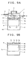
- FIG. 9 shows another related art, in which members or elements that are equivalent to those in FIG. 8 are given like reference numerals.
- a diesel filter 1 includes a cup-shaped case 2 forming an outer shell, and a cap 3 detachably attached to an upper opening end of the case 2.
- the cap 3 is provided with a fuel supply pipe 4, a fuel discharge pipe 5, and a hand pump 6. The supply and discharge of fuel are performed through the fuel supply pipe 4 and the fuel discharge pipe 5 respectively, and air is released from the fuel supply system by means of the hand pump 6.
- a filter member 11 Housed in the case 2 is a filter member 11 that includes an element 8 and a holding member 9 for holding an upper end of the element 8. Formed below the filter member 11 is a water reservoir 12.
- the holding member 9 includes a first member 9a that constitutes a lower portion thereof and holds the element 8, a second member 9b arranged above the first member 9a with a space 13 therebetween, and a third member 9c provided on the second member 9b.
- An inlet port 15 is so provided as to pass through the center of the second member 9b and the third member 9c, while an outlet port 14 is so provided as to pass through the first member 9a to the third member 9c.
- the case 2, the element 8, and the holding member 9 including the first member 9a to the third member 9c are assembled into a single unit by caulking to form a cartridge case as illustrated in FIG. 9B .
- a diesel filter 1 is assembled by fixing the cartridge case to the cap 3.
- Fuel is introduced to the space 13, from the upper center thereof, between the first member 9a and the second member 9b through the fuel supply pipe 4 and the inlet port 15 as indicated by arrows (1), (2), and (3).
- the fuel is then introduced to the water reservoir 12 through a fuel channel 7a formed between an inner peripheral surface of the case 2 and an outer peripheral surface of the element 8.
- the introduced fuel changes its direction by 180° in the water reservoir 12, and moves upward.
- the fuel is filtered by passing through the element 8 and discharged from a fuel discharge pipe 5 through the outlet port 14 as indicated by arrows (4), (5) and (6).
- water is separated.
- the separated water has a larger specific gravity than the fuel, so that the water is retained in the water reservoir 12 (see Japanese Patent Application Publication No. JP-A-8-291776 ).
- the degree of water atomization is lower than the related art device shown in FIG. 8 , and therefore the amount of water passing through the element 8 reduces.
- its structure is more complicated and the number of parts is larger than the device shown in FIG. 8 .
- the unit is assembled by caulking the components, which complicates its disassembly. Accordingly, the related art device is not desirable in terms of environmental friendliness.
- WO 97/40910 A1 discloses a filter apparatus including a fluted filter element in a filter housing having a first open end and a second closed end.
- the filter element includes fluted filter media coiled into a cylindrical shape and may include an end cap for support and fluid control. Fluid flows into the open end and either around the filter to the closed end and back through the filter element or through the filter element to the closed end and then back through a central opening in the filter element.
- US 2,563,548 discloses a filter in accordance with the preamble of claim 1. Specifically, US 2,563,548 discloses a filter for separating water from gasoline or similar liquids and for removing any solid foreign particles.
- the filter includes a case embodied by a glass bowl which is provided at an open upper end with a flange extending outwardly therefrom and is of a size to engage soft resilient gasket which fits within a recess in the undersurface of a cap embodied as a head an outer lower edge of which is threaded for a quick detachable connection with a ring having internal threads for engaging with the threads of the head and being provided with an inwardly extending lip to engage beneath the flange of the bowl.
- a side-flow diesel filter is employed in which the fuel introduced from the fuel inlet port to a portion above the element-holding member is introduced to the water reservoir via the passage formed between the inner peripheral surface of the case and the outer peripheral surface of the element.
- the fuel is dispersed and introduced to the water reservoir.
- the atomization of water in the water reservoir is suppressed and more water can thus be retained in the water reservoir, as compared to the case where a center-flow diesel filter is employed.
- the filter member is detachably housed in the case, so that disassembly can be easily performed at the time of disposal of the diesel filter.
- the element may include a wound filter element.
- Wound filter elements can be produced easily and thus at low cost, as compared to, for example, pleated filter elements.
- the filtration area of a wound filter element is larger than that of a pleated filter element, resulting in improved filtration efficiency.
- the case may be made of metal. In this case, the impact resistance of the case is made high, which increases the degree of freedom of the mounting position of the diesel filter, resulting in further reduction in production cost.
- the element-holding member includes a flange provided at an outer periphery of the element-holding member and having openings through which the fuel flows.
- the flange is arranged so as to be held by the cap and the case when the opening of the case is closed by the cap.
- the fuel inlet port may be offset from the center of the filter member.
- FIG. 8 shows a side-flow diesel filter in which fuel is introduced to a water reservoir via a passage provided between an inner peripheral surface of a case and an outer peripheral surface of an element.
- a fuel inlet port is arranged at the center, and water contained in the fuel introduced from the fuel inlet port is substantially evenly dispersed in all directions and then introduced to the water reservoir, allowing the water to be atomized accordingly.
- the foregoing diesel filter according to the invention may be used as a diesel filter for vehicles. By doing so, it is possible to reduce the production cost of vehicle parts, and consequently that of vehicles, as well as enhancing their environmental adaptability.
- FIG. 1 shows a cross sectional view of a diesel filter
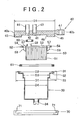
- FIG. 2 shows a cross sectional view of the diesel filter before assembly
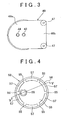
- FIG. 3 shows a plan view of a cap
- FIG. 4 shows a plan view of an element-holding member
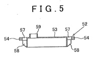
- FIG. 5 shows a cross sectional view taken along line V-V of the element-holding member shown in FIG. 4 .
- a diesel filter according to an embodiment of the invention may be employed in a fuel system of any machine, for example, a vehicle, construction machine, forklift, generator, and the like. In the following, however, a diesel filter used in a fuel system of a vehicle will be described.
- a diesel filter 20 includes a cup-shaped case 30 forming an outer shell, a cap 40 for closing an upper opening of the case 30, a filter member 50 housed in the case 30, and a fastening member 70 for coupling the case 30 and the cap 40.
- the case 30 is a hollow cylindrical member made of metal having an opening at an upper portion thereof.
- a horizontal ring-shaped upper stepped portion 31 having a diameter of D1 is formed such that it outwardly protrudes from an upper end of the case 30.
- a horizontal ring-shaped middle stepped portion 32 having a diameter of D2 is formed below the upper stepped portion 31.
- a horizontal ring-shaped lower stepped portion 33 having a diameter of D3 is formed below the middle stepped portion 32.
- the case 30 houses the cylindrical filter member 50 having a diameter of D4 that is disposed such that the bottom surface of the filter member 50 is lower than the stepped portion 33, thereby defining a space as a water reservoir 62 to be described later.
- a drain cock 34 that is opened when the amount of water in the water reservoir 62 reaches a predetermined value or more so as to discharge the retained water.
- the discharge of the water is performed, for example, in such a manner that a water level detector such as a float switch is provided in the water reservoir, and the water is discharged manually or automatically in accordance with signals received from the detector.
- the case 30 is made of metal, which enhances impact resistance of the case.
- the case may thus be arranged even at the bottom of the vehicle, which is likely to be hit by road debris, such as pebbles, thrown by the tires. Note that, if a safety place is ensured for the case in terms of impact resistance, the case may be made of plastic instead of metal.
- the cap 40 made of metal includes a round portion 40a and a square portion 40b, taking a forward-round and backward-square shape.
- a fuel inlet port 41 and a fuel outlet port 42 are provided in the round shape portion 40a so as to be opened in a vertical direction.
- a fuel supply pipe 43 is pressed into the fuel inlet port 41, and fuel in a fuel tank (not shown) is supplied through the fuel supply pipe 43.
- a fuel discharge pipe 44 is pressed into the fuel outlet port 42, and filtered fuel is fed to a fuel injection pump (not shown) through the fuel discharge pipe 44.
- the round portion 40a has a substantially the same diameter as the diameter D1 of the upper stepped portion 31 of the case 30.
- the outer peripheral surface of the lower portion of the round portion 40a is formed with a thread 45 to which the fastening member 70 can be attached.
- Formed at the bottom of the round portion 40a is a concave portion 46 having the same diameter as the diameter D3 of the lower stepped portion 33 of the case 30.
- the square portion 40b is integrally formed at one end of the round portion 40a.
- two set holes 47 are provided at left and right ends of the outer periphery of the square portion 40b so as to pass therethrough in the vertical direction.
- the diesel filter 20 is installed to an appropriate portion in the engine compartment of the vehicle by inserting bolts (not shown) into the set holes 47.
- the cap 40 is not provided with a hand pump such as that illustrated in FIG. 8 and FIG. 9 .
- the cap 40 may include a hand pump.
- the cap 40 is made of metal in the above description.
- the cap 40 may be made of plastic.
- the filter member 50 includes an element 51 and an element-holding member 52.
- the element 51 is a cylindrical member formed by bonding a plain filter element and a wavy filter element and then winding the bonded filter elements.
- fuel passages are arranged in an up-and-down direction. With this arrangement, fuel flows through many passages formed in the element 51, thereby catching foreign matter contained in the fuel by means of the filter elements.
- the outer diameter of the element 51 is made smaller than the inner diameter D4 of the water reservoir 62 of the case 30, and when the element 51 is housed in the case 30, a fuel passage 64 is defined therebetween.
- the element-holding member 52 is an integrally formed member made of plastic, and includes a body 53, a flange 54, and connecting portions 55.
- the body 53 is an umbrella-shaped member made by turning a shallow vessel upside down, and is downwardly opened.
- the inner diameter of the body 53 is substantially the same as the outer diameter of the element 51.
- the element 51, to the outer periphery of which an adhesive is applied, is inserted into the body 53 such that a small space 56 is left above the element 51.
- the body 53 and the element 51 are bonded together water-tightly with the adhesive.
- the filter member 50 is formed.
- an opening 59 for fuel outlet having a tubular shape is stood on the top surface of the body 53.
- the opening 59 for fuel outlet is provided at a position facing the fuel outlet port 42 of the cap 40.
- the flange 54 is a ring-shaped member, and its outer diameter is smaller than the inner diameter D2 of the middle stepped portion 32 of the case 30.
- the inner diameter of the flange 54 is substantially the same as the inner diameter D3 of the lower stepped portion 33 of the case 30.
- the bottom of the flange 54 is placed and held on the top surface of the middle stepped portion 32.
- a ring shaped second sealing material 61 is placed and held on the middle steeped portion 32 of the case 30.
- the outer diameter of the second sealing material 61 is slightly smaller than the inner diameter D2 of the middle stepped portion 32.
- the flange 54 is placed and held on the middle stepped portion 32 to the inner side of the second sealing member 61.
- the second sealing member 61 is thus sandwiched between the bottom surface of the cap 40 and the top surface of the middle stepped portion 32, thereby forming a sealed portion illustrated by circle A in FIG. 1 .
- the flange 54 is also held by the bottom surface of the cap 40 and the top surface of the nuddle stepped portion 32. Note that the order of placing the second sealing material 61 and the flange 54 may be reversed.
- the connecting portions 55 are provided for connecting the outer peripheral surface of the upper portion of the body 53 and the inner peripheral surface of the flange 54. As shown in FIG. 4 , the connecting portions 55 are radially arranged at 6 positions at equal intervals. Six arc-shaped notches 57, whose shapes are substantially identical to each other, are provided at equal intervals between the respective connecting portions 55. The fuel flows down, via the notches 57, to the fuel passage 64 extending in the up and down direction.
- ribs 58 are radially arranged at 6 positions below the connecting portions 55.
- the ribs 58 are identical in shape and length to the connecting portions 55.
- the outer diameter of the two opposing ribs 58 is slightly smaller than the inner diameter D3 of the lower stepped portion 33.
- the fastening member 70 is L-shaped in cross section, made of metal or plastic, and formed with a thread 71 on an inner side thereof.
- the fastening member 70 is inserted from below the case 30 and then attached to the case 30 by tightening the thread 71 to the thread 45 formed on the outer peripheral surface of the cap 40 until the horizontal surface of the bottom of the fastening member 70 comes in contact with the bottom surface of the upper stepped portion 31.
- the case 30 and the cap 40 are integrally fixed.
- the filter member 50 is housed in the case 30 such that the element 51 is inserted down to substantially the half depth of the case 30, thereby forming the water reservoir 62 below the element 51, as well as forming an upper chamber 63 between the top surface of the element-holding member 52 and the bottom surface of the concave portion 46 of the cap 40. Further, the fuel passage 64 is formed between the inner surface of the portion of the case 30 having the diameter of D4 and the outer peripheral surface of the element 51. Thus, the fuel supplied to the upper chamber 63 is introduced to the water reservoir 62 via the notches 57 formed between the body 53 and the flange 54 and the fuel passage 64.
- the fuel inlet port 41 is aligned with, when the opening of the case 30 is closed by the cap 40, substantially the center of the filter member 50, while the fuel outlet port 42 is offset from the center of the filter member 50.
- their arrangement may be modified so as to align the fuel outlet port 42 with substantially the center of the filter member 50 and to offset the fuel inlet port 41 from it.
- the fuel introduced from the fuel supply pipe 43 into the diesel filter 20 as shown by arrow (1) is dispersed in all directions in the upper chamber 63. Then, the fuel flows down from the notches 57 to the fuel passage 64 formed between the inner surface of the case 30 and the outer peripheral surface of the element 51 as shown by arrows (2), and is introduced to the water reservoir 62 as shown by arrows (3).
- Water content in the fuel is separated in the water reservoir 62, and the fuel free from the water content moves upward as shown by arrows (4). Then, the fuel passes through the element 51 as shown by arrows (5) to remove foreign matter contained in the fuel. After removal of the foreign matter, the fuel reaches the upper space 56 above the element 51. Then, the fuel is discharged via the opening 59 for fuel outlet, the fuel outlet port 42 and the fuel discharge pipe 44 as shown by arrow (6).
- the filter member 50 employed in the embodiment of the invention is detachable and includes only two members, namely, the element 51 and the element-holding member 52 provided above the element 51.
- production cost can be reduced, and when the element 51 clogs, it is sufficient to replace only the filter member 50 with new one.
- only one sealed portion is provided between the filter member 50 and another member (the cap 40 in this case), which is denoted by circle B in FIG. 1 . Accordingly, the structure of the filter element is more simplified than that of the related art including two sealed portions denoted by circle B and circle C in FIG. 12.
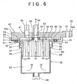
- FIG. 6 is a cross sectional view showing a second embodiment of the diesel filter. This embodiment is different from the first embodiment in that the fuel inlet port 41, which is provided in the cap 40 and into which the fuel supply pipe 43 is pressed, is arranged to deviate from the center of the filter member 50. Note that elements or members equivalent to those in the first embodiment are denoted by like reference numerals and detailed description thereof will be omitted.
- the case 30, the cap 40, the filter member 50, and the fastening member 70 included in the diesel filter 20 are the same as those in the first embodiment except the position of the fuel inlet port 41 provided in the cap 40. More specifically, the fuel inlet port 41 provided in the cap 40 is offset from the center of the filter member 50.
- FIG. 6 shows the case where the fuel outlet port 42 is aligned with the center of the filter member 50. However, the fuel outlet port 42 may be offset from it.
- the element-holding member 80 shown in FIG 9 may be employed as element-holding means.
- FIG. 7 shows experiment results.
- FIG. 7 shows the volume of water retained in the water reservoir 62 in units of mL with respect to the flow rate of the fuel flowing into the diesel filter 20.
- the water volumes mL corresponding to respective flow rates were compared.
- the least water volume was detected in the case of using a center-flow diesel filter shown in FIG. 8 .
- the water volume was increased in the following order: a center-inlet side-flow diesel filter shown in FIG.
- the experiment results are analyzed in the following manner.
- the fuel flowing down from the fuel inlet port 41 to the top surface of the filter member 50 disperses in all directions while flowing over the horizontal top surface of the filter member 50.
- the distance that the fuel flows before flowing down to the fuel passage 64 varies.
- the water content in the fuel becomes larger water droplets, falling down to the water reservoir 62.
- the large droplets are thus retained in the water reservoir 62 substantially as they are.
- the fuel introduced from the fuel supply pipe 43 into the diesel filter 20, i.e., through a position offset from the center of the diesel filter 20, as shown by arrow (1) is dispersed in all directions in the upper chamber 63.
- the fuel flows down from the notch spaces 78 to the fuel passage 64 formed between the inner surface of the case 30 and the outer peripheral surface of the element 51 as shown by arrows (2), and is introduced to the water reservoir 62 as shown by arrows (3).
- the fuel flowing as illustrated by arrow (2) on the right side of FIG. 6 flows a long distance, so that the water contained in the fuel is atomized to fall down to the fuel passage 64.
- the fuel flowing as illustrated by arrow (2) on the left side of FIG. 6 flows a short distance before flowing down to the fuel passage 64. Accordingly, the water contained in the fuel falls down through the fuel passage 64 in the form of large water droplets to fall down to the water reservoir 62, and the large water droplets are retained therein as they are.
- Water content in the fuel is separated in the water reservoir 62, and the fuel, from which a larger amount of water has been removed, moves upward as shown by arrows (4). Then, the fuel passes through the element 51 as shown by arrows (5) so that foreign matter contained in the fuel is removed. After removal of the foreign matter, the fuel reaches the upper space 56 above the element 51. Then, the fuel is discharged via the opening 59 for fuel outlet, the fuel outlet port 42 and the fuel discharge pipe 44 as shown by arrow (6).
- the water retainability in the water reservoir 62 can be improved more.
- the filter member 50 is detachable and includes only two members, namely, the element 51 and the element-holding member 75 provided above the element 51. Therefore, when the element 51 clogs, it is sufficient to replace only the filter member 50 with new one, thereby reducing maintenance cost.
- only one sealed portion of the filter member 50 and another member is provided as in the case of the first embodiment. Accordingly, the structure of the filter element is more simplified than that of the related art including two sealed portions.
- a side-flow diesel filter is employed in which the fuel introduced from the fuel inlet port to a portion above the element-holding member is introduced to the water reservoir via the passage formed between the inner peripheral surface of the case and the outer peripheral surface of the element.
- the fuel is dispersed and introduced to the water reservoir.
- the atomization of water in the water reservoir is suppressed and more water can thus be retained in the water reservoir, compared to the case where a center-flow diesel filter is employed.
- the filter member is detachably housed in the case, and sealing between the filter member and another member is accomplished, when the opening of the case is closed by the cap, by the sealed portion at the opening only.
- the structure of the filter member can be simplified, and the number of parts can be reduced, thereby reducing production cost.
- disassembly can be easily performed at the time of disposal of the diesel filter, which is advantageous to deal with environmental issues.
- the element by forming the element from a wound filter element, the production becomes easier compared to, for example, a known pleated filter element. Thus, production cost is reduced.
- the filtration area can be increased compared to a pleated filter element, resulting in improved filtration efficiency.
- the outer peripheral surface of the element-holding member is provided with a flange having notches for allowing the fuel to flow therethrough.
- the flange is held by the cap and the case.
- the fuel inlet port is offset from the center of the filter member in the foregoing embodiments of the invention.
- fuel is introduced to the water reservoir via the passage provided between the inner peripheral surface of the case and the outer peripheral surface of the element.
- this diesel filter has a certain degree of water retainability, the water contained in the fuel introduced from the fuel inlet port is substantially evenly dispersed in all directions due to the fuel inlet being arranged at the center, and the fuel is then introduced to the water reservoir, allowing the water to be atomized to a certain degree.
- a side-flow diesel filter realizes better water retainability than a center-flow diesel filter, as indicated by the diagram in FIG. 7 .
- experiment results show that the more the fuel inlet port is offset from the center of the filter member, the more water retainability is enhanced.
- the experiment results are analyzed as follows. When the distance between the fuel inlet port and a point at which the fuel begins to fall down is short, the fuel flows only a short distance before falling down, so atomization of the water in the fuel is not much facilitated. As a result, large droplets of water fall down to the water reservoir, and are retained in the water reservoir as they are.
Landscapes
- Chemical & Material Sciences (AREA)
- Engineering & Computer Science (AREA)
- Chemical Kinetics & Catalysis (AREA)
- Combustion & Propulsion (AREA)
- Mechanical Engineering (AREA)
- General Engineering & Computer Science (AREA)
- Filtration Of Liquid (AREA)
- Cooling, Air Intake And Gas Exhaust, And Fuel Tank Arrangements In Propulsion Units (AREA)
Description
- The invention relates to a diesel filter provided in a fuel supply system of a vehicle and the like, particularly to a diesel filter that improves water separation performance and/or reduces maintenance costs.
- Diesel engines have long been used as engines for vehicles and the like. In a diesel engine, a filter filters light oil in a fuel tank, and an injection pump compresses the filtered fuel to a high pressure, and an injector injects the fuel to a combustion chamber of the engine, whereby self-combustion takes place in the combustion chamber.
- Incidentally, fuel includes foreign matters, for example, water, dust, and solid undesirable materials such as rust. These foreign matters need to be removed because inclusion thereof results in reduced combustion efficiency and wear of the injector or the like. Diesel filters are, therefore, provided to deal with such problems. More specifically, water content in fuel is classified into dissolved water and free water. Dissolved water causes no negative effects, because it flows smoothly in fuel channels and is consumed together with fuel. Meanwhile, free water may cause some problems as follows. Free water appears in fuel when: rainwater intrudes into the fuel during fueling; water droplets formed by moisture in the air intrude into the fuel; or the water dissolved in the fuel is separated therefrom due to a decrease in fuel temperature. Such free water is large in specific gravity compared to light oil, so that it stagnates in the injection pump and the like, thus generating rust and stick. For this reason, free water particularly needs to be removed using a diesel filter.
- Auto parts are required to be easily disassembled taking consideration of cost reduction and environmental conservation. Diesel filters for automobile use are desired to have such structure.
-
FIG. 8 shows a diesel filter related to the invention. Adiesel filter 1 includes a cup-shaped case 2 forming an outer shell, and acap 3 detachably attached to an upper opening end of thecase 2. Thecap 3 is provided with afuel supply pipe 4, afuel discharge pipe 5, and ahand pump 6. The supply and discharge of fuel are performed through thefuel supply pipe 4 and thefuel discharge pipe 5 respectively, and air is released from the fuel supply system by means of thehand pump 6. - Housed in the
case 2 is afilter member 11 that includes anelement 8 having afuel passage 7 at the center thereof, and anupper holding member 9 and alower holding member 10 for holding the upper and lower ends of theelement 8. Awater reservoir 12 is formed below thefilter member 11. - Fuel is introduced to the
water reservoir 12 through thefuel supply pipe 4 and thefuel passage 7 as indicated by arrows (1), (2) and (3). The introduced fuel changes its direction by 180° in thewater reservoir 12, and then moves upward. Then, the fuel is filtered by passing through theelement 8 and discharged from thefuel discharge pipe 5 as indicated by arrows (4), (5) and (6). When the flow direction of the fuel changes in thewater reservoir 12, water is separated from the fuel. The separated water has a larger specific gravity than the fuel, so that the water is retained in the water reservoir 12 (see Japanese Patent Application Publication No.JP-A-2003-172224 - Note that the amount of water retained in the
water reservoir 12 becomes larger as the flow rate of fuel passing through theelement 8 reduces. The experiment using the related art device shown inFIG 8 shows that the amount of water retained in thewater reservoir 12 is not large when the flow rate of fuel is high, as indicated by, for example, the curve denoted by "CENTER FLOW" in the diagram ofFIG. 7 . Conceivably, this is because all the fuel flows into thewater reservoir 12 through thefuel passage 7 arranged at the center of theelement 8, so that the fuel flowing into thewater reservoir 12 strongly strikes the center of the bottom thereof, whereby the free water is pushed up to the bottom of theelement 8, and a portion thereof is discharged from thefuel discharge pipe 5 together with the fuel as indicated by arrows (4), (5) and (6). Thus, it has been proved that desired water retainability can not be always achieved in thewater reservoir 12 of the related art device. - In this related art device, in addition to a sealed position illustrated by circle A between the
case 2 and thecap 3, two other sealed positions illustrated by circles B and C are required between thefiltering portion 11 and another member. Thus, additional man-hours and further accuracy are required for assembly work. - Moreover, when the
filter member 11 is held by thecase 2 and thecap 3, thefiltering portion 11 is held by utilizing the upper and lower surfaces of thefilter member 11. Accordingly, anupper holding member 9 and alower holding member 10 are essential. Thus, the number of parts of thefilter member 11 is increased for these two members. This also leads to a problem that disassembly work becomes complicated at the time of disposal. -
FIG. 9 shows another related art, in which members or elements that are equivalent to those inFIG. 8 are given like reference numerals. Adiesel filter 1 includes a cup-shaped case 2 forming an outer shell, and acap 3 detachably attached to an upper opening end of thecase 2. Thecap 3 is provided with afuel supply pipe 4, afuel discharge pipe 5, and ahand pump 6. The supply and discharge of fuel are performed through thefuel supply pipe 4 and thefuel discharge pipe 5 respectively, and air is released from the fuel supply system by means of thehand pump 6. - Housed in the
case 2 is afilter member 11 that includes anelement 8 and aholding member 9 for holding an upper end of theelement 8. Formed below thefilter member 11 is awater reservoir 12. Theholding member 9 includes afirst member 9a that constitutes a lower portion thereof and holds theelement 8, asecond member 9b arranged above thefirst member 9a with aspace 13 therebetween, and athird member 9c provided on thesecond member 9b. Aninlet port 15 is so provided as to pass through the center of thesecond member 9b and thethird member 9c, while anoutlet port 14 is so provided as to pass through thefirst member 9a to thethird member 9c. Thecase 2, theelement 8, and theholding member 9 including thefirst member 9a to thethird member 9c are assembled into a single unit by caulking to form a cartridge case as illustrated inFIG. 9B . Then, adiesel filter 1 is assembled by fixing the cartridge case to thecap 3. - Fuel is introduced to the
space 13, from the upper center thereof, between thefirst member 9a and thesecond member 9b through thefuel supply pipe 4 and theinlet port 15 as indicated by arrows (1), (2), and (3). The fuel is then introduced to thewater reservoir 12 through afuel channel 7a formed between an inner peripheral surface of thecase 2 and an outer peripheral surface of theelement 8. The introduced fuel changes its direction by 180° in thewater reservoir 12, and moves upward. Then, the fuel is filtered by passing through theelement 8 and discharged from afuel discharge pipe 5 through theoutlet port 14 as indicated by arrows (4), (5) and (6). When the flow direction of the fuel is changed in thewater reservoir 12, water is separated. The separated water has a larger specific gravity than the fuel, so that the water is retained in the water reservoir 12 (see Japanese Patent Application Publication No.JP-A-8-291776 - In this related art device, the degree of water atomization is lower than the related art device shown in
FIG. 8 , and therefore the amount of water passing through theelement 8 reduces. However, its structure is more complicated and the number of parts is larger than the device shown inFIG. 8 . Further, the unit is assembled by caulking the components, which complicates its disassembly. Accordingly, the related art device is not desirable in terms of environmental friendliness. - Further,
WO 97/40910 A1 -
US 2,563,548 discloses a filter in accordance with the preamble ofclaim 1. Specifically,US 2,563,548 discloses a filter for separating water from gasoline or similar liquids and for removing any solid foreign particles. The filter includes a case embodied by a glass bowl which is provided at an open upper end with a flange extending outwardly therefrom and is of a size to engage soft resilient gasket which fits within a recess in the undersurface of a cap embodied as a head an outer lower edge of which is threaded for a quick detachable connection with a ring having internal threads for engaging with the threads of the head and being provided with an inwardly extending lip to engage beneath the flange of the bowl. When the ring is screwed up, it will draw the bowl tightly against the gasket and hold the head, bowl and ring in tightly sealed relation, with the ring being sufficiently compressed so as to spring load the threaded connection and prevent from jarring loose or moving in a direction to release the threaded connection. - Starting from
US 2,563,548 , it is the object of the invention to provide a diesel filter of simplified structure which prevents fuel leakage by preventing excessive compression of a sealing material placed between a case and a cap of the diesel filter. - This object is solved by a diesel filter according to
claim 1. - According to the invention, firstly, a side-flow diesel filter is employed in which the fuel introduced from the fuel inlet port to a portion above the element-holding member is introduced to the water reservoir via the passage formed between the inner peripheral surface of the case and the outer peripheral surface of the element. Thus, the fuel is dispersed and introduced to the water reservoir. The atomization of water in the water reservoir is suppressed and more water can thus be retained in the water reservoir, as compared to the case where a center-flow diesel filter is employed. Secondly, the filter member is detachably housed in the case, so that disassembly can be easily performed at the time of disposal of the diesel filter.
- In the diesel filter according to the invention, the element may include a wound filter element. Wound filter elements can be produced easily and thus at low cost, as compared to, for example, pleated filter elements. In addition, the filtration area of a wound filter element is larger than that of a pleated filter element, resulting in improved filtration efficiency. Further, the case may be made of metal. In this case, the impact resistance of the case is made high, which increases the degree of freedom of the mounting position of the diesel filter, resulting in further reduction in production cost.
- In the diesel filter according to the invention, the element-holding member includes a flange provided at an outer periphery of the element-holding member and having openings through which the fuel flows. The flange is arranged so as to be held by the cap and the case when the opening of the case is closed by the cap. With this arrangement, it is possible to prevent a sealing material (a second sealing material 61) from being cut by excessive compression due to deformation of the case that is caused by collision (impact) and groove formation for retaining the sealing material (the second sealing material 61). Thus, fuel leakage can be prevented. Further, the structure for holding the filter member can be simplified, leading to further reduction in production cost.
- The fuel inlet port may be offset from the center of the filter member.
- For example,
FIG. 8 shows a side-flow diesel filter in which fuel is introduced to a water reservoir via a passage provided between an inner peripheral surface of a case and an outer peripheral surface of an element. In this diesel filter, a fuel inlet port is arranged at the center, and water contained in the fuel introduced from the fuel inlet port is substantially evenly dispersed in all directions and then introduced to the water reservoir, allowing the water to be atomized accordingly. Thus, it is considered that, although better than center-flow type diesel filters as indicated inFIG. 6 , the water retainability of the diesel filter shown inFIG. 8 is not sufficient. On the other hand, as indicated by the diagram inFIG. 6 , it was confirmed by experiment that offsetting the fuel inlet port from the center of the filter member enhances the water retainability. This fact is analyzed as follows. When the distance between the fuel inlet port and a point at which the fuel begins to fall down is short, the fuel flows only a short distance before falling down, so atomization of the water in the fuel is not much facilitated. As a result, large droplets of water fall down to the water reservoir, and are introduced to the water reservoir as they are. That is, the water retainability in the water reservoir is more enhanced. - The foregoing diesel filter according to the invention may be used as a diesel filter for vehicles. By doing so, it is possible to reduce the production cost of vehicle parts, and consequently that of vehicles, as well as enhancing their environmental adaptability.
- The foregoing and further objects, features and advantages of the invention will become apparent from the following description of preferred embodiments with reference to the accompanying drawings, wherein like numerals are used to represent like elements and wherein:
-
FIG. 1 is a cross sectional view of a diesel filter; -
FIG. 2 is a cross sectional view of the diesel filter before assembly; -
FIG. 3 is a plan view of a diesel filter; -
FIG. 4 is a plan view of an element-holding member; -
FIG. 5 is a cross sectional view of the element-holding member; -
FIG. 6 is a cross sectional view of another diesel filter; -
FIG. 7 is a characteristic diagram showing the volume of retained water of a center-flow diesel filter and a side-flow diesel filter; -
FIG. 8 is a cross sectional view of a diesel filter according to a related art; and -
FIG. 9 is a cross sectional view of another diesel filter according to the related art. -
FIG. 1 shows a cross sectional view of a diesel filter, andFIG. 2 shows a cross sectional view of the diesel filter before assembly.FIG. 3 shows a plan view of a cap, andFIG. 4 shows a plan view of an element-holding member.FIG. 5 shows a cross sectional view taken along line V-V of the element-holding member shown inFIG. 4 . A diesel filter according to an embodiment of the invention may be employed in a fuel system of any machine, for example, a vehicle, construction machine, forklift, generator, and the like. In the following, however, a diesel filter used in a fuel system of a vehicle will be described. - A
diesel filter 20 includes a cup-shapedcase 30 forming an outer shell, acap 40 for closing an upper opening of thecase 30, afilter member 50 housed in thecase 30, and afastening member 70 for coupling thecase 30 and thecap 40. - The
case 30 is a hollow cylindrical member made of metal having an opening at an upper portion thereof. A horizontal ring-shaped upper steppedportion 31 having a diameter of D1 is formed such that it outwardly protrudes from an upper end of thecase 30. A horizontal ring-shaped middle steppedportion 32 having a diameter of D2 is formed below the upper steppedportion 31. A horizontal ring-shaped lower steppedportion 33 having a diameter of D3 is formed below the middle steppedportion 32. Further, thecase 30 houses thecylindrical filter member 50 having a diameter of D4 that is disposed such that the bottom surface of thefilter member 50 is lower than the steppedportion 33, thereby defining a space as awater reservoir 62 to be described later. - Provided at the bottom of the
case 30 is adrain cock 34 that is opened when the amount of water in thewater reservoir 62 reaches a predetermined value or more so as to discharge the retained water. The discharge of the water is performed, for example, in such a manner that a water level detector such as a float switch is provided in the water reservoir, and the water is discharged manually or automatically in accordance with signals received from the detector. - The
case 30 is made of metal, which enhances impact resistance of the case. The case may thus be arranged even at the bottom of the vehicle, which is likely to be hit by road debris, such as pebbles, thrown by the tires. Note that, if a safety place is ensured for the case in terms of impact resistance, the case may be made of plastic instead of metal. - As shown in
FIG. 3 , thecap 40 made of metal includes around portion 40a and asquare portion 40b, taking a forward-round and backward-square shape. Afuel inlet port 41 and afuel outlet port 42 are provided in theround shape portion 40a so as to be opened in a vertical direction. Afuel supply pipe 43 is pressed into thefuel inlet port 41, and fuel in a fuel tank (not shown) is supplied through thefuel supply pipe 43. Afuel discharge pipe 44 is pressed into thefuel outlet port 42, and filtered fuel is fed to a fuel injection pump (not shown) through thefuel discharge pipe 44. - The
round portion 40a has a substantially the same diameter as the diameter D1 of the upper steppedportion 31 of thecase 30. The outer peripheral surface of the lower portion of theround portion 40a is formed with athread 45 to which thefastening member 70 can be attached. Formed at the bottom of theround portion 40a is aconcave portion 46 having the same diameter as the diameter D3 of the lower steppedportion 33 of thecase 30. Thesquare portion 40b is integrally formed at one end of theround portion 40a. As shown inFIG. 3 , two setholes 47 are provided at left and right ends of the outer periphery of thesquare portion 40b so as to pass therethrough in the vertical direction. Thediesel filter 20 is installed to an appropriate portion in the engine compartment of the vehicle by inserting bolts (not shown) into the set holes 47. - Note that, in the above description, the
cap 40 is not provided with a hand pump such as that illustrated inFIG. 8 andFIG. 9 . Thecap 40, however, may include a hand pump. Further, thecap 40 is made of metal in the above description. However, when a safe position for installation is secured in terms of impact resistance, thecap 40 may be made of plastic. - The
filter member 50 includes anelement 51 and an element-holdingmember 52. Theelement 51 is a cylindrical member formed by bonding a plain filter element and a wavy filter element and then winding the bonded filter elements. In theelement 51, fuel passages are arranged in an up-and-down direction. With this arrangement, fuel flows through many passages formed in theelement 51, thereby catching foreign matter contained in the fuel by means of the filter elements. The outer diameter of theelement 51 is made smaller than the inner diameter D4 of thewater reservoir 62 of thecase 30, and when theelement 51 is housed in thecase 30, afuel passage 64 is defined therebetween. - The element-holding
member 52 is an integrally formed member made of plastic, and includes abody 53, aflange 54, and connectingportions 55. Thebody 53 is an umbrella-shaped member made by turning a shallow vessel upside down, and is downwardly opened. The inner diameter of thebody 53 is substantially the same as the outer diameter of theelement 51. Theelement 51, to the outer periphery of which an adhesive is applied, is inserted into thebody 53 such that asmall space 56 is left above theelement 51. Thebody 53 and theelement 51 are bonded together water-tightly with the adhesive. Thus, thefilter member 50 is formed. - Further, an
opening 59 for fuel outlet having a tubular shape is stood on the top surface of thebody 53. Theopening 59 for fuel outlet is provided at a position facing thefuel outlet port 42 of thecap 40. When closing the opening of thecase 30 by thecap 40, a ring-shaped first sealingmaterial 60 is put around the outer periphery of theopening 59 for fuel outlet and then sandwiched between the bottom surface of thecap 40 and the top surface of the element-holdingmember 52, thereby forming a sealed portion illustrated by circle B inFIG. 1 . The leakage of the discharged fuel into the inlet side is thus inhibited. - The
flange 54 is a ring-shaped member, and its outer diameter is smaller than the inner diameter D2 of the middle steppedportion 32 of thecase 30. The inner diameter of theflange 54 is substantially the same as the inner diameter D3 of the lower steppedportion 33 of thecase 30. The bottom of theflange 54 is placed and held on the top surface of the middle steppedportion 32. When thecap 40 closes the opening of thecase 30, a ring shaped second sealingmaterial 61 is placed and held on the middle steepedportion 32 of thecase 30. The outer diameter of thesecond sealing material 61 is slightly smaller than the inner diameter D2 of the middle steppedportion 32. Next, theflange 54 is placed and held on the middle steppedportion 32 to the inner side of the second sealingmember 61. Thesecond sealing member 61 is thus sandwiched between the bottom surface of thecap 40 and the top surface of the middle steppedportion 32, thereby forming a sealed portion illustrated by circle A inFIG. 1 . At the same time, theflange 54 is also held by the bottom surface of thecap 40 and the top surface of the nuddle steppedportion 32. Note that the order of placing thesecond sealing material 61 and theflange 54 may be reversed. - The connecting
portions 55 are provided for connecting the outer peripheral surface of the upper portion of thebody 53 and the inner peripheral surface of theflange 54. As shown inFIG. 4 , the connectingportions 55 are radially arranged at 6 positions at equal intervals. Six arc-shapednotches 57, whose shapes are substantially identical to each other, are provided at equal intervals between the respective connectingportions 55. The fuel flows down, via thenotches 57, to thefuel passage 64 extending in the up and down direction. - Further,
ribs 58 are radially arranged at 6 positions below the connectingportions 55. Theribs 58 are identical in shape and length to the connectingportions 55. The outer diameter of the two opposingribs 58 is slightly smaller than the inner diameter D3 of the lower steppedportion 33. When thefilter member 50 is housed in thecase 30, theseribs 58 guide thefilter member 50 along the inner peripheral surface of the lower steppedportion 33 of thecase 30 so that the axes of theelement 51 and thecase 3, as well as the axes of thefuel outlet port 42 and theopening 59 for fuel outlet, substantially coincide with each other after housing thefilter member 50 in thecase 30. - The
fastening member 70 is L-shaped in cross section, made of metal or plastic, and formed with athread 71 on an inner side thereof. When thecap 40 closes the opening of thecase 30, the outer surface of the bottom of thecap 40 is placed on the top surface of the upper steppedportion 31 of thecase 30. Thefastening member 70 is inserted from below thecase 30 and then attached to thecase 30 by tightening thethread 71 to thethread 45 formed on the outer peripheral surface of thecap 40 until the horizontal surface of the bottom of thefastening member 70 comes in contact with the bottom surface of the upper steppedportion 31. Thus, thecase 30 and thecap 40 are integrally fixed. - The
filter member 50 is housed in thecase 30 such that theelement 51 is inserted down to substantially the half depth of thecase 30, thereby forming thewater reservoir 62 below theelement 51, as well as forming anupper chamber 63 between the top surface of the element-holdingmember 52 and the bottom surface of theconcave portion 46 of thecap 40. Further, thefuel passage 64 is formed between the inner surface of the portion of thecase 30 having the diameter of D4 and the outer peripheral surface of theelement 51. Thus, the fuel supplied to theupper chamber 63 is introduced to thewater reservoir 62 via thenotches 57 formed between thebody 53 and theflange 54 and thefuel passage 64. Thefuel inlet port 41 is aligned with, when the opening of thecase 30 is closed by thecap 40, substantially the center of thefilter member 50, while thefuel outlet port 42 is offset from the center of thefilter member 50. However, their arrangement may be modified so as to align thefuel outlet port 42 with substantially the center of thefilter member 50 and to offset thefuel inlet port 41 from it. - Next, the flow of the fuel will be described. The fuel introduced from the
fuel supply pipe 43 into thediesel filter 20 as shown by arrow (1) is dispersed in all directions in theupper chamber 63. Then, the fuel flows down from thenotches 57 to thefuel passage 64 formed between the inner surface of thecase 30 and the outer peripheral surface of theelement 51 as shown by arrows (2), and is introduced to thewater reservoir 62 as shown by arrows (3). - Water content in the fuel is separated in the
water reservoir 62, and the fuel free from the water content moves upward as shown by arrows (4). Then, the fuel passes through theelement 51 as shown by arrows (5) to remove foreign matter contained in the fuel. After removal of the foreign matter, the fuel reaches theupper space 56 above theelement 51. Then, the fuel is discharged via theopening 59 for fuel outlet, thefuel outlet port 42 and thefuel discharge pipe 44 as shown by arrow (6). - The
filter member 50 employed in the embodiment of the invention is detachable and includes only two members, namely, theelement 51 and the element-holdingmember 52 provided above theelement 51. Thus, production cost can be reduced, and when theelement 51 clogs, it is sufficient to replace only thefilter member 50 with new one. Moreover, only one sealed portion is provided between thefilter member 50 and another member (thecap 40 in this case), which is denoted by circle B inFIG. 1 . Accordingly, the structure of the filter element is more simplified than that of the related art including two sealed portions denoted by circle B and circle C in FIG. 12. -
FIG. 6 is a cross sectional view showing a second embodiment of the diesel filter. This embodiment is different from the first embodiment in that thefuel inlet port 41, which is provided in thecap 40 and into which thefuel supply pipe 43 is pressed, is arranged to deviate from the center of thefilter member 50. Note that elements or members equivalent to those in the first embodiment are denoted by like reference numerals and detailed description thereof will be omitted. - The
case 30, thecap 40, thefilter member 50, and thefastening member 70 included in thediesel filter 20 are the same as those in the first embodiment except the position of thefuel inlet port 41 provided in thecap 40. More specifically, thefuel inlet port 41 provided in thecap 40 is offset from the center of thefilter member 50.FIG. 6 shows the case where thefuel outlet port 42 is aligned with the center of thefilter member 50. However, thefuel outlet port 42 may be offset from it. Further, the element-holding member 80 shown inFIG 9 may be employed as element-holding means. -
FIG. 7 shows experiment results.FIG. 7 shows the volume of water retained in thewater reservoir 62 in units of mL with respect to the flow rate of the fuel flowing into thediesel filter 20. The water volumes mL corresponding to respective flow rates were compared. The least water volume was detected in the case of using a center-flow diesel filter shown inFIG. 8 . Then, the water volume was increased in the following order: a center-inlet side-flow diesel filter shown inFIG. 9 in which thefuel inlet port 41 is aligned with the center of thefilter member 50; a 20 mm-offset-inlet side-flow diesel filter in which thefuel inlet port 41 is offset from the center of thefilter member 50 by 20 mm; and a 30 mm-offset inlet side-flow diesel filter in which thefuel inlet port 41 is offset from the center of thefilter member 50 by 30 mm. The experiment results show that the more thefuel inlet port 41 is offset from the center of thefilter member 50, the more the water retainability in thewater reservoir 62 is enhanced. - The experiment results are analyzed in the following manner. The fuel flowing down from the
fuel inlet port 41 to the top surface of thefilter member 50 disperses in all directions while flowing over the horizontal top surface of thefilter member 50. When thefuel inlet port 41 is offset from the center of thefilter member 50, the distance that the fuel flows before flowing down to thefuel passage 64 varies. As the flow distance becomes shorter, the water content in the fuel becomes larger water droplets, falling down to thewater reservoir 62. The large droplets are thus retained in thewater reservoir 62 substantially as they are. - Next, the flow of the fuel will be described. The fuel introduced from the
fuel supply pipe 43 into thediesel filter 20, i.e., through a position offset from the center of thediesel filter 20, as shown by arrow (1) is dispersed in all directions in theupper chamber 63. Then, the fuel flows down from the notch spaces 78 to thefuel passage 64 formed between the inner surface of thecase 30 and the outer peripheral surface of theelement 51 as shown by arrows (2), and is introduced to thewater reservoir 62 as shown by arrows (3). In this case, the fuel flowing as illustrated by arrow (2) on the right side ofFIG. 6 flows a long distance, so that the water contained in the fuel is atomized to fall down to thefuel passage 64. Meanwhile, the fuel flowing as illustrated by arrow (2) on the left side ofFIG. 6 flows a short distance before flowing down to thefuel passage 64. Accordingly, the water contained in the fuel falls down through thefuel passage 64 in the form of large water droplets to fall down to thewater reservoir 62, and the large water droplets are retained therein as they are. - Water content in the fuel is separated in the
water reservoir 62, and the fuel, from which a larger amount of water has been removed, moves upward as shown by arrows (4). Then, the fuel passes through theelement 51 as shown by arrows (5) so that foreign matter contained in the fuel is removed. After removal of the foreign matter, the fuel reaches theupper space 56 above theelement 51. Then, the fuel is discharged via theopening 59 for fuel outlet, thefuel outlet port 42 and thefuel discharge pipe 44 as shown by arrow (6). - According to the second embodiment, the water retainability in the
water reservoir 62 can be improved more. Further, thefilter member 50 is detachable and includes only two members, namely, theelement 51 and the element-holding member 75 provided above theelement 51. Therefore, when theelement 51 clogs, it is sufficient to replace only thefilter member 50 with new one, thereby reducing maintenance cost. Moreover, only one sealed portion of thefilter member 50 and another member (thecap 40 in this case) is provided as in the case of the first embodiment. Accordingly, the structure of the filter element is more simplified than that of the related art including two sealed portions. - According to the first and second embodiments, firstly, a side-flow diesel filter is employed in which the fuel introduced from the fuel inlet port to a portion above the element-holding member is introduced to the water reservoir via the passage formed between the inner peripheral surface of the case and the outer peripheral surface of the element. Thus, the fuel is dispersed and introduced to the water reservoir. The atomization of water in the water reservoir is suppressed and more water can thus be retained in the water reservoir, compared to the case where a center-flow diesel filter is employed. Secondly, the filter member is detachably housed in the case, and sealing between the filter member and another member is accomplished, when the opening of the case is closed by the cap, by the sealed portion at the opening only. Thus, the structure of the filter member can be simplified, and the number of parts can be reduced, thereby reducing production cost. In addition, disassembly can be easily performed at the time of disposal of the diesel filter, which is advantageous to deal with environmental issues.
- Further, by forming the element from a wound filter element, the production becomes easier compared to, for example, a known pleated filter element. Thus, production cost is reduced. In addition, the filtration area can be increased compared to a pleated filter element, resulting in improved filtration efficiency.
- By making the case from a metal material, impact resistance of the case is improved. Thus, the degree of freedom of the mounting position of the diesel filter can be increased, resulting in further reduction in production cost.
- The outer peripheral surface of the element-holding member is provided with a flange having notches for allowing the fuel to flow therethrough. When the opening of the case is closed by the cap, the flange is held by the cap and the case. Thus, the structure for holding the filter member can be simplified, leading to further reduction in production cost. Further, it is possible to prevent the sealing material (the second sealing material 61) from being cut by excessive compression due to deformation of the case that is caused by collision (impact) and groove formation for retaining the sealing material (the second sealing material 61). Thus, fuel leakage can be prevented.
- The fuel inlet port is offset from the center of the filter member in the foregoing embodiments of the invention. Meanwhile, in the side-flow diesel filter shown in
FIG. 9 , fuel is introduced to the water reservoir via the passage provided between the inner peripheral surface of the case and the outer peripheral surface of the element. Although this diesel filter has a certain degree of water retainability, the water contained in the fuel introduced from the fuel inlet port is substantially evenly dispersed in all directions due to the fuel inlet being arranged at the center, and the fuel is then introduced to the water reservoir, allowing the water to be atomized to a certain degree. Nevertheless, it is true that such a side-flow diesel filter realizes better water retainability than a center-flow diesel filter, as indicated by the diagram inFIG. 7 . However, the water retainability of such a side-flow diesel filter is not always sufficient. On the other hand, as indicated by the diagram inFIG. 7 , experiment results show that the more the fuel inlet port is offset from the center of the filter member, the more water retainability is enhanced. The experiment results are analyzed as follows. When the distance between the fuel inlet port and a point at which the fuel begins to fall down is short, the fuel flows only a short distance before falling down, so atomization of the water in the fuel is not much facilitated. As a result, large droplets of water fall down to the water reservoir, and are retained in the water reservoir as they are.
Claims (8)
- A diesel filter, comprising a case (30) including an opening that is upwardly opened, a cap (40) detachably attached to the opening of the case (30), for closing the opening, a filter member (50) detachably housed in the case (30), and a ring-shaped sealing material (61) placed and held between the case (30) and the cap (40), the filter member (50) including an element (51) and an element-holding member (52) for holding the element (51), wherein, in a state where the filter member (50) is housed in the case (30), a water reservoir (62) is formed in the case (30) below the filter member (50), and a passage (64) is formed between an inner peripheral surface of the case (30) and an outer peripheral surface of the element (51) so as to introduce fuel that has been introduced to a portion above the element-holding member (52) into the water reservoir (62), and the element-holding member (52) has an opening (59) for allowing the fuel to flow out from the element (51), the opening (59) being in communication with a fuel outlet port (42) formed in the cap (40), the diesel filter characterized in that
the element-holding member (52) comprises a body (53) with an inner diameter which is substantially the same as the outer diameter of the element (51),
an upper part of the element (51) is inserted into the body (53) such that a space (56) is left above the element (51) between a top surface thereof and a bottom surface of the element-holding member (52),
the body (53) and the upper part of the element (51) are bonded together watertightly,
the element-holding member (52) further includes a flange (54) which is provided at an outer periphery of the element-holding member (52) and which includes openings (57) through which the fuel flows,
the case (30) comprises a horizontal ring-shaped upper stepped portion (31) which is formed such that it outwardly protrudes from an upper end of the case (30), a horizontal ring-shaped middle stepped portion (32) which is formed below the upper stepped portion (31), and a horizontal ring-shaped lower stepped portion (33) which is formed below the middle stepped portion (32),
the flange (54) is held by the cap (40) and the case (30) in a state where the flange (54) is placed on a top surface of the middle stepped portion (32) of the case (30) and the cap (40) is placed on a top surface of the upper stepped portion (31) of the case (30) and closes the opening of the case (30), and
the rinq-shaped sealing material (61) is placed and held on the top surface of the middle stepped portion (32) of the case (30) and is sandwiched between a bottom surface of the cap (40) and a top surface of the middle stepped portion (32),
wherein fuel introduced into the water reservoir (62) flows upwardly from the water reservoir (62) through the element (51), reaches the space (56) between the top surface of the element (51) and the bottom surface of the element-holding member (51), and is discharged via the opening (59) to the fuel outlet port (42). - The filter according to claim 1, wherein;
the element (51) includes a wound filter element. - The filter according to claim 1 or 2, wherein;
the case (30) is made of metal. - The filter according to any one of claims 1 to 3, wherein;
the fuel outlet port (42) passes through the cap (40) in a vertical direction. - The filter according to any one of claims 1 to 4, wherein;
the fuel is introduced to a portion above the element-holding member (52) from a fuel inlet port (41) which is formed in the cap (40) and passes through the cap (40) in a vertical direction, and
the fuel inlet port (41) is offset from the center of the filter member (51). - The filter according to any one of claims 1 to 5, further comprising:a fastening member (70) for fixing the case to the cap.
- The filter according to claim 6, wherein;
the fastening member (70) includes a thread, and the thread is tightened to a corresponding thread in the cap (40). - Fuel system of a vehicle, comprising a diesel filter according to any one of claims 1 to 7.
Applications Claiming Priority (1)
| Application Number | Priority Date | Filing Date | Title |
|---|---|---|---|
| JP2005308073A JP4298693B2 (en) | 2005-10-24 | 2005-10-24 | Diesel filter |
Publications (2)
| Publication Number | Publication Date |
|---|---|
| EP1776993A1 EP1776993A1 (en) | 2007-04-25 |
| EP1776993B1 true EP1776993B1 (en) | 2012-11-28 |
Family
ID=37571860
Family Applications (1)
| Application Number | Title | Priority Date | Filing Date |
|---|---|---|---|
| EP06022075A Not-in-force EP1776993B1 (en) | 2005-10-24 | 2006-10-20 | Diesel filter |
Country Status (3)
| Country | Link |
|---|---|
| US (1) | US7922004B2 (en) |
| EP (1) | EP1776993B1 (en) |
| JP (1) | JP4298693B2 (en) |
Families Citing this family (7)
| Publication number | Priority date | Publication date | Assignee | Title |
|---|---|---|---|---|
| JP4308246B2 (en) * | 2006-12-20 | 2009-08-05 | 京三電機株式会社 | Fuel filter |
| DE202007013281U1 (en) * | 2007-09-21 | 2007-11-22 | A. Kayser Automotive Systems Gmbh | liquid filters |
| US8419938B2 (en) * | 2007-11-19 | 2013-04-16 | Catepillar Inc. | Fluid filter system |
| US8741137B2 (en) * | 2010-03-12 | 2014-06-03 | Clean & Clear Corporation | Filtering methods and configurations |
| US9416758B2 (en) | 2012-12-21 | 2016-08-16 | Ford Global Technologies, Llc | Fuel filter |
| US11459986B2 (en) * | 2018-09-24 | 2022-10-04 | Baldwin Filters, Inc. | Obround filter element |
| CN113969853A (en) * | 2021-12-07 | 2022-01-25 | 赵云清 | Fuel filter for improving power |
Citations (3)
| Publication number | Priority date | Publication date | Assignee | Title |
|---|---|---|---|---|
| US2563548A (en) * | 1951-08-07 | Filter fob liquids | ||
| WO1997040910A1 (en) * | 1996-04-26 | 1997-11-06 | Donaldson Company, Inc. | Filtering device with corrugated and rolled filter media |
| EP1179358A1 (en) * | 2000-08-09 | 2002-02-13 | Filterwerk Mann + Hummel Gmbh | Gas conducting system with filter for dehumidification |
Family Cites Families (15)
| Publication number | Priority date | Publication date | Assignee | Title |
|---|---|---|---|---|
| US4456529A (en) | 1982-10-21 | 1984-06-26 | Applied Diesel Engineering, Inc. | Filter device for diesel engines |
| JPS60108759A (en) | 1983-11-17 | 1985-06-14 | Mitsubishi Electric Corp | Suspended air detector |
| US4668393A (en) * | 1985-05-14 | 1987-05-26 | Parker-Hannifin Corporation | Semipermeable baffle fuel filter |
| GB8626393D0 (en) * | 1986-11-05 | 1986-12-03 | Harwood Ltd C T | Liquid separators |
| US4751901A (en) * | 1987-10-13 | 1988-06-21 | Moor Stephen E | Composite oil filter |
| US4824567A (en) * | 1988-02-08 | 1989-04-25 | Filter Systems, Inc. | Fuel oil filter assembly |
| US4933093A (en) | 1989-04-20 | 1990-06-12 | Keller Russel D | Fuel filter |
| US5104537A (en) * | 1990-07-20 | 1992-04-14 | Donaldson Company, Inc. | High pressure hydraulic spin-on filter |
| US5879543A (en) * | 1994-04-13 | 1999-03-09 | Amini; Bijan | Filter and dehydrator apparatus with threaded collar |
| JP3646342B2 (en) | 1995-04-21 | 2005-05-11 | 株式会社デンソー | Filter element fixing structure |
| JPH10325373A (en) | 1997-05-27 | 1998-12-08 | Kubota Corp | Fuel filter |
| JP2003172224A (en) | 2001-12-05 | 2003-06-20 | Tokyo Roki Co Ltd | Fuel filter |
| FR2844461B1 (en) * | 2002-09-17 | 2004-11-26 | Filtrauto | GAS FILTER COMPRISING A WATER DETECTOR |
| US7410575B1 (en) * | 2003-05-27 | 2008-08-12 | Wix Filtration Corp Llc | Fluid filter and cap member |
| JP2005087930A (en) | 2003-09-19 | 2005-04-07 | Kyosan Denki Co Ltd | Filter |
-
2005
- 2005-10-24 JP JP2005308073A patent/JP4298693B2/en not_active Expired - Fee Related
-
2006
- 2006-10-20 US US11/583,780 patent/US7922004B2/en not_active Expired - Fee Related
- 2006-10-20 EP EP06022075A patent/EP1776993B1/en not_active Not-in-force
Patent Citations (3)
| Publication number | Priority date | Publication date | Assignee | Title |
|---|---|---|---|---|
| US2563548A (en) * | 1951-08-07 | Filter fob liquids | ||
| WO1997040910A1 (en) * | 1996-04-26 | 1997-11-06 | Donaldson Company, Inc. | Filtering device with corrugated and rolled filter media |
| EP1179358A1 (en) * | 2000-08-09 | 2002-02-13 | Filterwerk Mann + Hummel Gmbh | Gas conducting system with filter for dehumidification |
Also Published As
| Publication number | Publication date |
|---|---|
| JP4298693B2 (en) | 2009-07-22 |
| US7922004B2 (en) | 2011-04-12 |
| EP1776993A1 (en) | 2007-04-25 |
| JP2007113539A (en) | 2007-05-10 |
| US20070090043A1 (en) | 2007-04-26 |
Similar Documents
| Publication | Publication Date | Title |
|---|---|---|
| JP3119484B2 (en) | Fuel filter | |
| US7731845B2 (en) | Fuel filter | |
| KR101146883B1 (en) | Liquid separator, particularly oil separator for compressed air systems | |
| US4500425A (en) | Pump valve for liquid separator | |
| US9546626B2 (en) | Depth coalescing filter with barrier media patch | |
| US6475380B1 (en) | Hydraulic oil reservoir | |
| US10668410B2 (en) | Fuel filter comprising a fuel filter insert with a prefilter element and a main filter element | |
| EP3250304B1 (en) | Flow cap and method for directing a fluid through a filter | |
| US5578221A (en) | Fuel filter with improved hand primer | |
| EP3352878B1 (en) | End cap for filter element | |
| EP3250305B1 (en) | Filter assembly including flow cap | |
| JPH03157109A (en) | Fuel filter assembly and cartridge | |
| EP2732147B1 (en) | Filtering unit | |
| US6019890A (en) | Fuel filter with hand primer | |
| EP3147016B1 (en) | Filter element and filter assembly for separating fluids | |
| US20260115633A1 (en) | Liquid filter equipped with an anti-leakage valve | |
| US10765977B2 (en) | Fuel filter insert, and fuel filter comprising a prefilter element and a main filter element and comprising a water separating unit | |
| US7922004B2 (en) | Diesel filter | |
| US7906022B2 (en) | Diesel filter | |
| JP2003336559A (en) | Diesel filter | |
| CN1962026A (en) | Liquid trap device for gas | |
| JP4308246B2 (en) | Fuel filter | |
| JP2008151090A (en) | Diesel filter | |
| JP4000018B2 (en) | Diesel filter | |
| US12257535B2 (en) | Filter cartridge for a liquid such as fuel, the upper end plate of which including an automatic degassing valve |
Legal Events
| Date | Code | Title | Description |
|---|---|---|---|
| PUAI | Public reference made under article 153(3) epc to a published international application that has entered the european phase |
Free format text: ORIGINAL CODE: 0009012 |
|
| AK | Designated contracting states |
Kind code of ref document: A1 Designated state(s): AT BE BG CH CY CZ DE DK EE ES FI FR GB GR HU IE IS IT LI LT LU LV MC NL PL PT RO SE SI SK TR |
|
| AX | Request for extension of the european patent |
Extension state: AL BA HR MK YU |
|
| 17P | Request for examination filed |
Effective date: 20070424 |
|
| AKX | Designation fees paid |
Designated state(s): DE FR GB |
|
| 17Q | First examination report despatched |
Effective date: 20080507 |
|
| GRAP | Despatch of communication of intention to grant a patent |
Free format text: ORIGINAL CODE: EPIDOSNIGR1 |
|
| GRAS | Grant fee paid |
Free format text: ORIGINAL CODE: EPIDOSNIGR3 |
|
| RIN1 | Information on inventor provided before grant (corrected) |
Inventor name: OTSUBO, SUMINOBU Inventor name: NAGATA, SATOSHI Inventor name: MATSUSHITA, YOSHIHARU Inventor name: NISHI, YASUJI |
|
| GRAA | (expected) grant |
Free format text: ORIGINAL CODE: 0009210 |
|
| AK | Designated contracting states |
Kind code of ref document: B1 Designated state(s): DE FR GB |
|
| REG | Reference to a national code |
Ref country code: GB Ref legal event code: FG4D |
|
| RIN1 | Information on inventor provided before grant (corrected) |
Inventor name: NISHI, YASUJI Inventor name: NAGATA, SATOSHI Inventor name: OTSUBO, SUMINOBU Inventor name: MATSUSHITA, YOSHIHARU |
|
| REG | Reference to a national code |
Ref country code: DE Ref legal event code: R096 Ref document number: 602006033293 Country of ref document: DE Effective date: 20130124 |
|
| RAP2 | Party data changed (patent owner data changed or rights of a patent transferred) |
Owner name: TOYOTA JIDOSHA KABUSHIKI KAISHA Owner name: KYOSAN DENKI CO., LTD. |
|
| PLBE | No opposition filed within time limit |
Free format text: ORIGINAL CODE: 0009261 |
|
| STAA | Information on the status of an ep patent application or granted ep patent |
Free format text: STATUS: NO OPPOSITION FILED WITHIN TIME LIMIT |
|
| 26N | No opposition filed |
Effective date: 20130829 |
|
| REG | Reference to a national code |
Ref country code: DE Ref legal event code: R097 Ref document number: 602006033293 Country of ref document: DE Effective date: 20130829 |
|
| REG | Reference to a national code |
Ref country code: FR Ref legal event code: PLFP Year of fee payment: 10 |
|
| PGFP | Annual fee paid to national office [announced via postgrant information from national office to epo] |
Ref country code: GB Payment date: 20151021 Year of fee payment: 10 Ref country code: DE Payment date: 20151022 Year of fee payment: 10 |
|
| PGFP | Annual fee paid to national office [announced via postgrant information from national office to epo] |
Ref country code: FR Payment date: 20151023 Year of fee payment: 10 |
|
| REG | Reference to a national code |
Ref country code: GB Ref legal event code: 746 Effective date: 20160713 |
|
| REG | Reference to a national code |
Ref country code: DE Ref legal event code: R084 Ref document number: 602006033293 Country of ref document: DE |
|
| REG | Reference to a national code |
Ref country code: DE Ref legal event code: R119 Ref document number: 602006033293 Country of ref document: DE |
|
| GBPC | Gb: european patent ceased through non-payment of renewal fee |
Effective date: 20161020 |
|
| REG | Reference to a national code |
Ref country code: FR Ref legal event code: ST Effective date: 20170630 |
|
| PG25 | Lapsed in a contracting state [announced via postgrant information from national office to epo] |
Ref country code: DE Free format text: LAPSE BECAUSE OF NON-PAYMENT OF DUE FEES Effective date: 20170503 Ref country code: FR Free format text: LAPSE BECAUSE OF NON-PAYMENT OF DUE FEES Effective date: 20161102 Ref country code: GB Free format text: LAPSE BECAUSE OF NON-PAYMENT OF DUE FEES Effective date: 20161020 |