EP1776854A1 - Disc cutter bar - Google Patents
Disc cutter bar Download PDFInfo
- Publication number
- EP1776854A1 EP1776854A1 EP06021383A EP06021383A EP1776854A1 EP 1776854 A1 EP1776854 A1 EP 1776854A1 EP 06021383 A EP06021383 A EP 06021383A EP 06021383 A EP06021383 A EP 06021383A EP 1776854 A1 EP1776854 A1 EP 1776854A1
- Authority
- EP
- European Patent Office
- Prior art keywords
- transmission
- mower according
- disc mower
- side wall
- trough
- Prior art date
- Legal status (The legal status is an assumption and is not a legal conclusion. Google has not performed a legal analysis and makes no representation as to the accuracy of the status listed.)
- Granted
Links
Images


Classifications
-
- A—HUMAN NECESSITIES
- A01—AGRICULTURE; FORESTRY; ANIMAL HUSBANDRY; HUNTING; TRAPPING; FISHING
- A01D—HARVESTING; MOWING
- A01D34/00—Mowers; Mowing apparatus of harvesters
- A01D34/01—Mowers; Mowing apparatus of harvesters characterised by features relating to the type of cutting apparatus
- A01D34/412—Mowers; Mowing apparatus of harvesters characterised by features relating to the type of cutting apparatus having rotating cutters
- A01D34/63—Mowers; Mowing apparatus of harvesters characterised by features relating to the type of cutting apparatus having rotating cutters having cutters rotating about a vertical axis
- A01D34/64—Mowers; Mowing apparatus of harvesters characterised by features relating to the type of cutting apparatus having rotating cutters having cutters rotating about a vertical axis mounted on a vehicle, e.g. a tractor, or drawn by an animal or a vehicle
- A01D34/66—Mowers; Mowing apparatus of harvesters characterised by features relating to the type of cutting apparatus having rotating cutters having cutters rotating about a vertical axis mounted on a vehicle, e.g. a tractor, or drawn by an animal or a vehicle with two or more cutters
- A01D34/664—Disc cutter bars
Abstract
Description
Die Erfindung betrifft einen Mähbalken für Scheibenmähwerke zur Verbesserung der Schnittqualität, insbesondere für die Grünfutterernte, in der Landwirtschaft gemäß dem Oberbegriff des unabhängigen Anspruchs 1.The invention relates to a cutter bar for disc mowers for improving the quality of cut, in particular for the green fodder harvest, in agriculture according to the preamble of
Derartige Mähwerke gibt es in vielfältigen Variationen, wie beispielsweise Heck-, Seiten-, Front- oder gezogene Mähwerke, oder Kombinationen aus vorgenannten Mähwerken und auch für selbstfahrende Mähwerke, oder auch für Direktfutterschneidwerke für Feldhäcksler.Such mowers are available in a variety of variations, such as rear, side, front or towed mowers, or combinations of the aforementioned mowers and also for self-propelled mowers, or even for direct chucks for forage harvesters.
Bekannt sind Scheibenmähwerke mit umlaufenden Mähwerkzeugen, deren Mähklingen frei- bzw. schwenkbeweglich am Umfang der Mähscheiben an einem Zapfen aufgehängt sind. Die Mähklingen werden erst durch die Zentrifugalkraft stabilisiert und mähen das Grünfutter dann ohne Gegenschneide ab. Dabei sind die Mähscheiben antriebsseitig mit dem Motor eines Trägerfahrzeugs verbunden und zugleich in einer Antriebskette, bestehend aus Zahnrädern, welche unterhalb der Mähscheiben in einem geschlossenen Getriebegehäuse gelagert und untergebracht sind, eingebunden.Disk mowers are known with rotating mowing tools, the mowing blades are freely or pivotally suspended on the circumference of the mower discs on a pin. The mower blades are only stabilized by the centrifugal force and then mow the green fodder without counter cutting. The mower discs are the drive side connected to the engine of a host vehicle and at the same time in a drive chain consisting of gears, which are stored and housed below the mower discs in a closed gear housing integrated.
Bekannt sind Getriebegehäuse, bestehend aus abgekanteten Stahlblechwannen mit einem verschraubten oder verschweißten oberen Getriebedeckel, indem die Getriebekette und die Mähscheiben gelagert sind. Durch die Fertigungstechnik des Abkantens sind die Stahlblechwannen in ihrer Längserstreckung als Prisma ausgebildet, welches den Nachteil beinhaltet, dass die von den Flugkreisen der Messerklingen überdeckten Schnittflächen stärker eingeschränkt sind, als dieses zwingend notwendig wäre, so dass dieses das Mähbild insbesondere bei am Boden liegendem Grünfutter negativ beeinträchtigt, wodurch die unerwünschte Streifenbildung durch ungleichmäßige Stoppellänge im Mähbild gefördert wird.Are known transmission housing, consisting of bent steel trays with a screwed or welded upper gear cover by the transmission chain and the mowing discs are stored. Through the production technology of the chamfering the steel sheet pans are formed in their longitudinal extent as a prism, which includes the disadvantage that the overlapped by the flight circles of the knife blades cutting surfaces are more limited than this would be mandatory, so this negatively affects the mowing especially when lying on the ground green fodder, whereby the unwanted streaking is promoted by uneven stubble length in the mowing image.
Die Erfindung befasst sich mit diesem Problem der unerwünschten Streifenbildung, und damit, das Schneidverhalten und die Schnittqualität von Scheibenmähwerken zu verbessern.The invention addresses this problem of unwanted streaking and thus improving the cutting performance and cut quality of disc mowers.
Gelöst wird die Aufgabe der Erfindung mit den kennzeichnenden Merkmalen des Anspruchs 1. Weitere vorteilhafte Ausgestaltungen der Erfindung sind den abhängigen Ansprüchen, der Beschreibung und den Figurendarstellungen zu entnehmen.The object of the invention is achieved with the characterizing features of
Das Scheibenmähwerk nach der Erfindung besitzt ein Getriebegehäuse, welches eine vergrößerte Schnittfläche zum Mähen des Grünfutters am Boden und damit eine große Angriffsfläche für die Mähklingen darbietet. Erreicht wird dieses, indem die vordere Kontur des Getriebegehäuses so ausgestaltet ist, dass die Zahnräder der Getriebekette möglichst eng von der Seitenwand wellenförmig umschlossen werden. Die damit einhergehende Schwächung des Flächenträgheitsmoments im Querschnitt des Getriebegehäuses kann durch eine verstärkte Seitenwand des Getriebegehäuses kompensiert werden. Bevorzugt ist daher die Seitenwand dabei als Hohlprofil ausgebildet. Das Hohlprofil kann dabei gleichzeitig als Kühlmittel führendes Element ausgebildet sein, welches dazu dienen kann, dem Getriebegehäuse die Abwärme des Getriebeöls zu entziehen, um somit die Lebensdauer des Getriebeöls zu erhöhen.The Scheibenmähwerk according to the invention has a gear housing, which presents an enlarged cutting surface for mowing the green fodder on the ground and thus a large attack surface for the Mähklingen. This is achieved by the front contour of the gear housing is designed so that the gears of the transmission chain are as close as possible enclosed by the side wall wavy. The concomitant weakening of the area moment of inertia in the cross section of the transmission housing can by a reinforced side wall of the Gearbox be compensated. Preferably, therefore, the side wall is designed as a hollow profile. The hollow profile can be formed at the same time as a coolant leading element, which can serve to extract the waste heat of the transmission oil to the transmission housing, thus increasing the life of the transmission oil.
Nähere Einzelheiten der Erfindung sind den nachfolgenden Figurendarstellungen und deren Beschreibungen zu entnehmen.Further details of the invention are given in the following figure representations and their descriptions.
Es zeigen:
- Fig. 1
- zeigt einen Mähbalken in einer Draufsicht mit offenem Getriebegehäuse, so dass die Antriebskette sichtbar ist
- Fig. 2
- zeigt den Mähbalken in einer Ansicht von hinten entgegen der Fahrtrichtung
- Fig. 3
- zeigt die Untenansicht des Mähbalkens
- Fig. 4
- zeigt einen Ausschnitt aus der Untenansicht gemäß Ansicht X des Mähbalkens der Fig. 2 in perspektivischer Ansicht
- Fig. 5
- zeigt den Ausschnitt analog Fig. 4, jedoch mit geöffnetem Getriebegehäuse, so dass ein Teil der Antriebskette sichtbar ist
- Fig. 6
- zeigt einen Ausschnitt aus der Untenansicht gemäß Ansicht Y des Mähbalkens der Fig. 2 in perspektivischer Ansicht
- Fig. 7
- zeigt den Ausschnitt analog Fig. 6, jedoch mit geöffnetem Getriebegehäuse, so dass ein Teil der Antriebskette sichtbar ist
- Fig. 8
- zeigt die Ansicht Fig. 7 in diametraler Ansicht
- Fig.9
- zeigt das Mähwerk gemäß Fig.1 in einer Draufsicht ohne Mähscheiben zur besseren Kenntlichmachung des wellenförmigen Verlaufs der Außenwand des Getriebegehäuses
- Fig.10
- zeigt das Mähwerk gemäß Fig.1 in einer Draufsicht ohne Mähscheiben in vereinfachter Darstellung mit Kenntlichmachung des Zugewinns an Schnittfläche
- Fig.11 1
- zeigt den Schnitt A-A durch den Mähbalken gemäß Fig.4
- Fig.12
- zeigt den Schnitt A-A durch den Mähbalken gemäß Fig.4, jedoch mit einer alternativen Ausführung der vorderen Seitenwandausgestaltung
- Fig.13
- zeigt die Einzelheit Z gemäß Fig.12 in vergrößerter Darstellung
- Fig.14
- zeigt die Einzelheit Z gemäß Fig.12 in vergrößerter Darstellung jedoch mit einer alternativen Ausführung der vorderen Seitenwandausgestaltung als vollwandiger Querschnitt
- Fig. 1
- shows a cutter bar in a plan view with open gear housing, so that the drive chain is visible
- Fig. 2
- shows the cutter bar in a view from the rear against the direction of travel
- Fig. 3
- shows the bottom view of the cutter bar
- Fig. 4
- shows a section of the bottom view according to view X of the cutter bar of Fig. 2 in a perspective view
- Fig. 5
- shows the detail analogous to Fig. 4, but with the gearbox open, so that a part of the drive chain is visible
- Fig. 6
- shows a section of the bottom view according to view Y of the cutter bar of Fig. 2 in a perspective view
- Fig. 7
- shows the detail analogous to FIG. 6, but with the gearbox housing open, so that a part of the drive chain is visible
- Fig. 8
- shows the view Fig. 7 in diametric view
- Figure 9
- shows the mower according to Figure 1 in a plan view without mowing discs for better identification of the wave-shaped course of the outer wall of the gear housing
- Figure 10
- shows the mower according to Figure 1 in a plan view without mowing discs in a simplified representation with identification of the gain in cutting surface
- Fig. 11
- shows the section AA through the cutter bar according to Figure 4
- Figure 12
- shows the section AA through the cutter bar according to Figure 4, but with an alternative embodiment of the front side wall configuration
- Figure 13
- shows the detail Z of Figure 12 in an enlarged view
- Figure 14
- shows the detail Z of Figure 12 in an enlarged view, however, with an alternative embodiment of the front side wall configuration as a solid-walled cross-section
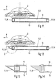
In Fig. 1 ist ein Mähbalken 1 in einer Draufsicht mit offenem Getriebegehäuse 8 dargestellt, so dass die Antriebskette 12 mit den Stirnrädern 6 sichtbar ist. Das offene Getriebegehäuse 8 dient lediglich der besseren Sichtbarmachung und Beschreibung der Antriebskette 12, bestehend aus den in Reihe liegenden Stirnrädern 6 einschließlich der Zahnritzel zum Antrieb der Mähscheiben 2. Die Antriebskette 12 besteht somit aus den Stirnrädern 6 und den Ritzeln 5, welche antriebsseitig mit dem Motor eines Trägerfahrzeugs in Verbindung stehen.In Fig. 1, a
In Fig. 2 ist der Mähbalken 1 in einer Ansicht entgegen der Fahrtrichtung F von hinten, und in Fig. 3 die Untenansicht des Mähbalkens 1 dargestellt.In Fig. 2, the
In Fig. 4 ist ein Ausschnitt aus der Untenansicht gemäß Ansicht X des Mähbalkens 1 der Fig. 2 in perspektivischer Ansicht, und in Fig. 5 ist analog der Fig. 4 das Getriebegehäuse in geöffnetem Zustand, jedoch mit geöffnetem Getriebegehäuse dargestellt, so dass ein Teil der Antriebskette sichtbar ist. In Fig. 6 ist ein Ausschnitt aus der Untenansicht gemäß Ansicht Y des Mähbalkens der Fig. 2 in perspektivischer Ansicht dargestellt und Fig. 7 zeigt den Ausschnitt analog Fig. 6, jedoch mit geöffnetem Getriebegehäuse 8, so dass ein Teil der Antriebskette 12, bestehend aus den Stirnrädern 6 und den Ritzeln 5, sichtbar ist.In Fig. 4 is a detail of the bottom view according to view X of the
Oberhalb des Mähbalkens 1 befinden sich in bekannter Anordnung die äußeren Mähscheiben 3 mit aufgesetzten Fördertrommeln 13 und den inneren Mähscheiben 2. Die äußeren und inneren Mähscheiben sind an ihrem Umfang in bekannter Weise mit Mähklingen 4 bestückt, deren äußere Kontur während des Umlaufs der Mähscheiben die Flugkreise 7 überstreichen. Die Antriebskette 12 besteht aus den Stirnrädern 6 und den Ritzeln 5, wobei die Ritzel 5 eine Antriebswelle aufweisen, welche im Getriebedeckel 9 des Getriebegehäuses 8 gelagert ist und wobei die Mähscheiben 2,3 mit dem jeweiligen Ritzel 5 eine drehfeste Verbindung eingehen.Above the
Die Getriebeseitenwand 11 des Getriebegehäuses 8 besteht aus einem Hohlprofil 14, welches wie in Fig. 7 bzw. Fig. 8 dargestellt, der Kontur der Antriebskette 12 folgend, diese umschließt. Dabei ist in Fig. 8 ein Ausschnitt aus dem Mähbalken 1 gemäß Fig. 2 die Ansicht Y ohne den Getriebewannenboden 15 dargestellt. In dem Ausführungsbeispiel ist das Hohlprofil 14 als Rechteckhohlprofil dargestellt.The
Das Hohlprofil 14 kann wahlweise entweder mit dem Getriebedeckel 10 oder mit dem Getriebewannenboden verschweißt sein, so dass Getriebewannenboden und Getriebedeckel beispielsweise miteinander verschraubt werden können. Möglich ist auch, dass Getriebewannenboden und Getriebewannendeckel nach der Montage der Getriebekette dauerhaft miteinander verschweißt werden. Dadurch bedingt, dass das Hohlprofil 14 als Getriebeseitenwand die Ritzel 5 und die Stirnräder 6 möglichst eng umschließt, können die Konturkreise der Mähklingen eine größere Fläche überdecken, als dieses der Fall wäre, wenn der Mähbalken an der Vorder- bzw. Hinterseite eine gerade verlaufende Kontur aufweisen würde.The
In Fig. 8 zeigt die Ansicht Fig. 7 in einer diametralen Ansicht und Fig.9 und Fig.10 zeigen das Mähwerk gemäß Fig.1 in einer Draufsicht ohne Mähscheiben. Fig.9 zeigt damit in anschaulicher Darstellung den wellenförmigen Verlauf der vorderen Kontur 16 und auch einen wellenförmigen Verlauf der hinteren Kontur 17 der Seitenwand 11 des Getriebegehäuses 8. Insbesondere in Fahrtrichtung F vor dem Getriebegehäuses 8 wird damit der schraffierte Zugewinn an Schnittfläche 18,19 in den Wellentälern 21 der vorderen Kontur 16 deutlich, welche von den umlaufenden Mähklingen 4 innerhalb der Konturkreises 7 liegend, zusätzlich gegenüber einer gerade verlaufenden Linie 20, welche die Abschlusskante eines abgekanteten Blechgehäuses bilden würde, überdeckt werden und somit von den Klingen mähtechnisch erreichbar sind.FIG. 8 shows the view in FIG. 7 in a diametrical view, and FIGS. 9 and 10 show the mower according to FIG. 1 in a plan view without mowing disks. 9 shows in an illustrative representation the undulating course of the
Fig.11 zeigt den Schnitt A-A durch den Mähbalken gemäß Fig.4, wobei die Getriebeseitenwand 11 des Getriebegehäuses 8 als Rechteck-Hohlprofil 14 ausgebildet ist. Fig.12 zeigt den Schnitt A-A durch den Mähbalken analog Fig.4, jedoch mit einer alternativen Ausführung der Ausgestaltung vorderen Seitenwand 11 als Hohlprofil 14 jedoch mit einer schrägen Abweisfläche 22, die das Übergleiten von Bodenunebenheiten durch geringere Wiederstandskräfte begünstigt. Fig.13 zeigt die Einzelheit Z gemäß Fig.12 in vergrößerter Darstellung und Fig.14 zeigt die Einzelheit Z gemäß Fig.12 in vergrößerter Darstellung jedoch mit einer alternativen Ausführung der vorderen Seitenwandausgestaltung mit einem vollwandiger Querschnitt 23. Dabei ist der Getriebedeckel 10 und der Getriebewannenboden 15 mit der Getriebeseitenwand 11 mittels einer Nietverbindung 24 als Ausführungsbeispiel einer möglichen Verbindungstechnik dargestellt.11 shows the section AA through the cutter bar according to Figure 4, wherein the
Getriebewannenboden (15), und Getriebedeckel (10) sind somit als planebene scheibenförmige Bauteile ausgebildet sind, welche die Getriebeseitenwand (11) nach der Sandwichbauweise zwischen sich aufnehmen.Gear tray bottom (15), and gear cover (10) are thus formed as a flat disc-shaped components which receive the transmission side wall (11) according to the sandwich construction between them.
Getriebewannenboden (15), Getriebeseitenwand (11) und Getriebedeckel (10) können als separate Einzelteile ausgebildet, die lösbar zusammengefügt, das Getriebegehäuse (8) bilden.Transmission trough bottom (15), transmission side wall (11) and gear cover (10) can be formed as separate items that are detachably joined together, the transmission housing (8).
Wahlweise kann die Getriebewanne (9) auch lösbar zusammengefügt sein mit dem Getriebedeckel (10) das Getriebegehäuse (8) oder alternativ können Getriebewannenboden (15) und Getriebeseitenwand (11) ebenso eine unlösbar miteinander verbundene Einheit als Getriebewanne (9) bilden.Optionally, the transmission pan (9) can also be releasably joined together with the transmission cover (10) the transmission housing (8) or alternatively the transmission trough bottom (15) and transmission side wall (11) also form a non-releasably interconnected unit as a transmission trough (9).
Ebenso ist es auch möglich, dass Getriebedeckel (10) und Getriebeseitenwand (11) eine unlösbar miteinander verbundene Einheit bilden die aber mit dem Getriebeboden (15) wiederum eine lösbare Einheit bilden.Likewise, it is also possible that the gear cover (10) and the transmission side wall (11) form an inseparable unit which, however, together with the gear base (15) form a detachable unit.
In einer weiteren Ausgestaltungsmöglichkeit können Getriebewannenboden (15), Getriebeseitenwand (11) und Getriebedeckel (10) separate Einzelteile bilden, die unlösbar zusammengefügt, das Getriebegehäuse (8) bilden.In a further embodiment, the transmission trough bottom (15), the transmission side wall (11) and the gear cover (10) may form separate individual parts which, when unsolvable, form the transmission housing (8).
Dabei kann die unlösbare Verbindung beispielsweise eine Schweissverbindung oder eine .Klebeverbindung sein oder auch eine Mischverbindung aus Klebeverbindung oder Vernietung sein.In this case, the insoluble compound may be, for example, a welded connection or a .Klebeverbindung or even a mixed compound of adhesive or riveting.
- 11
- MähbalkenCutting Bar
- 22
- innere Mähscheibeinner mower disc
- 33
- äußere Mähscheibeouter mower disc
- 44
- Mähklingemower blade
- 55
- Ritzelpinion
- 66
- Stirnräderspur gears
- 77
- Flugkreiscircle
- 88th
- Getriebegehäusegearbox
- 99
- Getriebewannetransmission pan
- 1010
- Getriebedeckeltransmission cover
- 1111
- GetriebeseitenwandTransmission sidewall
- 1212
- Antriebskettedrive chain
- 1313
- Fördertrommelconveyor drum
- 1414
- Hohlprofilhollow profile
- 1515
- GetriebewannenbodenTransmission trough base
- 1616
- vordere Konturfront contour
- 1717
- hintere Konturrear contour
- 1818
- Zugewinn an SchnittflächeGain in cutting area
- 1919
- Zugewinn an SchnittflächeGain in cutting area
- 2020
- gerade Liniestraight line
- 2121
- Wellentaltrough
- 2222
- schrägen Abweisflächesloping deflecting surface
- 2323
- vollwandiger Querschnittsolid wall cross-section
- 2424
- Nietverbindungrivet
- FF
- Fahrtrichtungdirection of travel
Claims (18)
Applications Claiming Priority (1)
| Application Number | Priority Date | Filing Date | Title |
|---|---|---|---|
| DE102005050187A DE102005050187A1 (en) | 2005-10-18 | 2005-10-18 | Scheibenmähwerk |
Publications (2)
| Publication Number | Publication Date |
|---|---|
| EP1776854A1 true EP1776854A1 (en) | 2007-04-25 |
| EP1776854B1 EP1776854B1 (en) | 2008-12-17 |
Family
ID=37547035
Family Applications (1)
| Application Number | Title | Priority Date | Filing Date |
|---|---|---|---|
| EP06021383A Not-in-force EP1776854B1 (en) | 2005-10-18 | 2006-10-12 | Disc cutter bar |
Country Status (3)
| Country | Link |
|---|---|
| EP (1) | EP1776854B1 (en) |
| AT (1) | ATE417496T1 (en) |
| DE (2) | DE102005050187A1 (en) |
Citations (5)
| Publication number | Priority date | Publication date | Assignee | Title |
|---|---|---|---|---|
| NL7100850A (en) * | 1965-09-17 | 1971-05-25 | ||
| DE2640704A1 (en) * | 1975-09-11 | 1977-03-17 | Lely Nv C Van Der | GYRO MACHINE |
| US4237679A (en) * | 1977-03-30 | 1980-12-09 | Lely Nv C Van Der | Mowing machine |
| EP0965258A1 (en) * | 1998-06-18 | 1999-12-22 | Maschinenfabrik Bernard Krone GmbH | Mowing machine |
| FR2840765A1 (en) * | 2002-06-14 | 2003-12-19 | Kuhn Sa | Rotary mower comprises housing consisting of upper and lower parts and front component of greater thickness than upper part, cutting member connected to housing through guide bearing connected by pin anchored in front component |
-
2005
- 2005-10-18 DE DE102005050187A patent/DE102005050187A1/en not_active Withdrawn
-
2006
- 2006-10-12 DE DE502006002366T patent/DE502006002366D1/en active Active
- 2006-10-12 AT AT06021383T patent/ATE417496T1/en active
- 2006-10-12 EP EP06021383A patent/EP1776854B1/en not_active Not-in-force
Patent Citations (5)
| Publication number | Priority date | Publication date | Assignee | Title |
|---|---|---|---|---|
| NL7100850A (en) * | 1965-09-17 | 1971-05-25 | ||
| DE2640704A1 (en) * | 1975-09-11 | 1977-03-17 | Lely Nv C Van Der | GYRO MACHINE |
| US4237679A (en) * | 1977-03-30 | 1980-12-09 | Lely Nv C Van Der | Mowing machine |
| EP0965258A1 (en) * | 1998-06-18 | 1999-12-22 | Maschinenfabrik Bernard Krone GmbH | Mowing machine |
| FR2840765A1 (en) * | 2002-06-14 | 2003-12-19 | Kuhn Sa | Rotary mower comprises housing consisting of upper and lower parts and front component of greater thickness than upper part, cutting member connected to housing through guide bearing connected by pin anchored in front component |
Also Published As
| Publication number | Publication date |
|---|---|
| ATE417496T1 (en) | 2009-01-15 |
| DE102005050187A1 (en) | 2007-06-14 |
| EP1776854B1 (en) | 2008-12-17 |
| DE502006002366D1 (en) | 2009-01-29 |
Similar Documents
| Publication | Publication Date | Title |
|---|---|---|
| EP1776855B1 (en) | Disc cutter bar | |
| DE3149887C2 (en) | ||
| DE2722554A1 (en) | MOWER | |
| EP0566981B1 (en) | Screen arrangement | |
| AT390162B (en) | CUTTER BARS WITH DISC WHEELS AROUND NEARBAL AXIS | |
| DE2640704A1 (en) | GYRO MACHINE | |
| EP0891693B1 (en) | Disc cutter bar and mower device | |
| DE3526333A1 (en) | MOTORBOW MOWER | |
| DE10055366A1 (en) | Eccentric drive, especially for a hand-held implement | |
| DE102006042990B3 (en) | Strainer | |
| EP0057936A2 (en) | Rotary-scythe mower | |
| DE112011105538B4 (en) | Cutting knife | |
| DE2832902C2 (en) | Mower conditioner | |
| DE102011016284B4 (en) | disc mower | |
| EP1776854B1 (en) | Disc cutter bar | |
| DE2843063A1 (en) | MOWER | |
| EP1353544B1 (en) | Cutting and transport device for a line-independent cutting tool | |
| DE102010011123A1 (en) | Cutting unit for a harvester | |
| EP2508061B1 (en) | Disc mower | |
| EP1369019B1 (en) | Disc cutter bar | |
| DE102009028410A1 (en) | Flat Knife blade for agricultural combine harvester i.e. combine, has edge extended parallel to longitudinal axis of rotor, and slot dividing knife blade into set of members, where edge is cut against longitudinally extending knife blade | |
| EP1285565B1 (en) | Cutting device and mower or cutter | |
| DE19821655C2 (en) | mowing machine | |
| DE10115652C1 (en) | Pneumatic conveyor, for field chopper, has cylindrical housing containing rotor mounted on shaft, with rocker shovels, circular discs, segments and tines. | |
| DE917706C (en) | Grain harvester for threshing the standing stalk |
Legal Events
| Date | Code | Title | Description |
|---|---|---|---|
| PUAI | Public reference made under article 153(3) epc to a published international application that has entered the european phase |
Free format text: ORIGINAL CODE: 0009012 |
|
| AK | Designated contracting states |
Kind code of ref document: A1 Designated state(s): AT BE BG CH CY CZ DE DK EE ES FI FR GB GR HU IE IS IT LI LT LU LV MC NL PL PT RO SE SI SK TR |
|
| AX | Request for extension of the european patent |
Extension state: AL BA HR MK YU |
|
| 17P | Request for examination filed |
Effective date: 20071025 |
|
| AKX | Designation fees paid |
Designated state(s): AT BE BG CH CY CZ DE DK EE ES FI FR GB GR HU IE IS IT LI LT LU LV MC NL PL PT RO SE SI SK TR |
|
| 17Q | First examination report despatched |
Effective date: 20071213 |
|
| GRAP | Despatch of communication of intention to grant a patent |
Free format text: ORIGINAL CODE: EPIDOSNIGR1 |
|
| GRAS | Grant fee paid |
Free format text: ORIGINAL CODE: EPIDOSNIGR3 |
|
| GRAA | (expected) grant |
Free format text: ORIGINAL CODE: 0009210 |
|
| AK | Designated contracting states |
Kind code of ref document: B1 Designated state(s): AT BE BG CH CY CZ DE DK EE ES FI FR GB GR HU IE IS IT LI LT LU LV MC NL PL PT RO SE SI SK TR |
|
| REG | Reference to a national code |
Ref country code: GB Ref legal event code: FG4D Free format text: NOT ENGLISH |
|
| REG | Reference to a national code |
Ref country code: CH Ref legal event code: EP |
|
| REG | Reference to a national code |
Ref country code: IE Ref legal event code: FG4D Free format text: LANGUAGE OF EP DOCUMENT: GERMAN |
|
| REF | Corresponds to: |
Ref document number: 502006002366 Country of ref document: DE Date of ref document: 20090129 Kind code of ref document: P |
|
| PG25 | Lapsed in a contracting state [announced via postgrant information from national office to epo] |
Ref country code: LT Free format text: LAPSE BECAUSE OF FAILURE TO SUBMIT A TRANSLATION OF THE DESCRIPTION OR TO PAY THE FEE WITHIN THE PRESCRIBED TIME-LIMIT Effective date: 20081217 |
|
| PG25 | Lapsed in a contracting state [announced via postgrant information from national office to epo] |
Ref country code: SI Free format text: LAPSE BECAUSE OF FAILURE TO SUBMIT A TRANSLATION OF THE DESCRIPTION OR TO PAY THE FEE WITHIN THE PRESCRIBED TIME-LIMIT Effective date: 20081217 Ref country code: NL Free format text: LAPSE BECAUSE OF FAILURE TO SUBMIT A TRANSLATION OF THE DESCRIPTION OR TO PAY THE FEE WITHIN THE PRESCRIBED TIME-LIMIT Effective date: 20081217 Ref country code: FI Free format text: LAPSE BECAUSE OF FAILURE TO SUBMIT A TRANSLATION OF THE DESCRIPTION OR TO PAY THE FEE WITHIN THE PRESCRIBED TIME-LIMIT Effective date: 20081217 Ref country code: PL Free format text: LAPSE BECAUSE OF FAILURE TO SUBMIT A TRANSLATION OF THE DESCRIPTION OR TO PAY THE FEE WITHIN THE PRESCRIBED TIME-LIMIT Effective date: 20081217 Ref country code: LV Free format text: LAPSE BECAUSE OF FAILURE TO SUBMIT A TRANSLATION OF THE DESCRIPTION OR TO PAY THE FEE WITHIN THE PRESCRIBED TIME-LIMIT Effective date: 20081217 |
|
| NLV1 | Nl: lapsed or annulled due to failure to fulfill the requirements of art. 29p and 29m of the patents act | ||
| REG | Reference to a national code |
Ref country code: IE Ref legal event code: FD4D |
|
| PG25 | Lapsed in a contracting state [announced via postgrant information from national office to epo] |
Ref country code: IE Free format text: LAPSE BECAUSE OF FAILURE TO SUBMIT A TRANSLATION OF THE DESCRIPTION OR TO PAY THE FEE WITHIN THE PRESCRIBED TIME-LIMIT Effective date: 20081217 Ref country code: BG Free format text: LAPSE BECAUSE OF FAILURE TO SUBMIT A TRANSLATION OF THE DESCRIPTION OR TO PAY THE FEE WITHIN THE PRESCRIBED TIME-LIMIT Effective date: 20090317 Ref country code: RO Free format text: LAPSE BECAUSE OF FAILURE TO SUBMIT A TRANSLATION OF THE DESCRIPTION OR TO PAY THE FEE WITHIN THE PRESCRIBED TIME-LIMIT Effective date: 20081217 Ref country code: EE Free format text: LAPSE BECAUSE OF FAILURE TO SUBMIT A TRANSLATION OF THE DESCRIPTION OR TO PAY THE FEE WITHIN THE PRESCRIBED TIME-LIMIT Effective date: 20081217 Ref country code: ES Free format text: LAPSE BECAUSE OF FAILURE TO SUBMIT A TRANSLATION OF THE DESCRIPTION OR TO PAY THE FEE WITHIN THE PRESCRIBED TIME-LIMIT Effective date: 20090328 |
|
| PG25 | Lapsed in a contracting state [announced via postgrant information from national office to epo] |
Ref country code: CZ Free format text: LAPSE BECAUSE OF FAILURE TO SUBMIT A TRANSLATION OF THE DESCRIPTION OR TO PAY THE FEE WITHIN THE PRESCRIBED TIME-LIMIT Effective date: 20081217 Ref country code: SE Free format text: LAPSE BECAUSE OF FAILURE TO SUBMIT A TRANSLATION OF THE DESCRIPTION OR TO PAY THE FEE WITHIN THE PRESCRIBED TIME-LIMIT Effective date: 20090317 Ref country code: IS Free format text: LAPSE BECAUSE OF FAILURE TO SUBMIT A TRANSLATION OF THE DESCRIPTION OR TO PAY THE FEE WITHIN THE PRESCRIBED TIME-LIMIT Effective date: 20090417 Ref country code: PT Free format text: LAPSE BECAUSE OF FAILURE TO SUBMIT A TRANSLATION OF THE DESCRIPTION OR TO PAY THE FEE WITHIN THE PRESCRIBED TIME-LIMIT Effective date: 20090518 |
|
| PG25 | Lapsed in a contracting state [announced via postgrant information from national office to epo] |
Ref country code: SK Free format text: LAPSE BECAUSE OF FAILURE TO SUBMIT A TRANSLATION OF THE DESCRIPTION OR TO PAY THE FEE WITHIN THE PRESCRIBED TIME-LIMIT Effective date: 20081217 |
|
| PLBE | No opposition filed within time limit |
Free format text: ORIGINAL CODE: 0009261 |
|
| STAA | Information on the status of an ep patent application or granted ep patent |
Free format text: STATUS: NO OPPOSITION FILED WITHIN TIME LIMIT |
|
| PG25 | Lapsed in a contracting state [announced via postgrant information from national office to epo] |
Ref country code: DK Free format text: LAPSE BECAUSE OF FAILURE TO SUBMIT A TRANSLATION OF THE DESCRIPTION OR TO PAY THE FEE WITHIN THE PRESCRIBED TIME-LIMIT Effective date: 20081217 |
|
| 26N | No opposition filed |
Effective date: 20090918 |
|
| BERE | Be: lapsed |
Owner name: CLAAS SAULGAU G.M.B.H. Effective date: 20091031 |
|
| PG25 | Lapsed in a contracting state [announced via postgrant information from national office to epo] |
Ref country code: MC Free format text: LAPSE BECAUSE OF NON-PAYMENT OF DUE FEES Effective date: 20091031 |
|
| PG25 | Lapsed in a contracting state [announced via postgrant information from national office to epo] |
Ref country code: GR Free format text: LAPSE BECAUSE OF FAILURE TO SUBMIT A TRANSLATION OF THE DESCRIPTION OR TO PAY THE FEE WITHIN THE PRESCRIBED TIME-LIMIT Effective date: 20090318 Ref country code: BE Free format text: LAPSE BECAUSE OF NON-PAYMENT OF DUE FEES Effective date: 20091031 |
|
| PG25 | Lapsed in a contracting state [announced via postgrant information from national office to epo] |
Ref country code: IT Free format text: LAPSE BECAUSE OF FAILURE TO SUBMIT A TRANSLATION OF THE DESCRIPTION OR TO PAY THE FEE WITHIN THE PRESCRIBED TIME-LIMIT Effective date: 20081217 |
|
| PG25 | Lapsed in a contracting state [announced via postgrant information from national office to epo] |
Ref country code: LU Free format text: LAPSE BECAUSE OF NON-PAYMENT OF DUE FEES Effective date: 20091012 |
|
| REG | Reference to a national code |
Ref country code: CH Ref legal event code: PL |
|
| GBPC | Gb: european patent ceased through non-payment of renewal fee |
Effective date: 20101012 |
|
| PG25 | Lapsed in a contracting state [announced via postgrant information from national office to epo] |
Ref country code: HU Free format text: LAPSE BECAUSE OF FAILURE TO SUBMIT A TRANSLATION OF THE DESCRIPTION OR TO PAY THE FEE WITHIN THE PRESCRIBED TIME-LIMIT Effective date: 20090618 |
|
| PG25 | Lapsed in a contracting state [announced via postgrant information from national office to epo] |
Ref country code: CH Free format text: LAPSE BECAUSE OF NON-PAYMENT OF DUE FEES Effective date: 20101031 Ref country code: LI Free format text: LAPSE BECAUSE OF NON-PAYMENT OF DUE FEES Effective date: 20101031 |
|
| PG25 | Lapsed in a contracting state [announced via postgrant information from national office to epo] |
Ref country code: TR Free format text: LAPSE BECAUSE OF FAILURE TO SUBMIT A TRANSLATION OF THE DESCRIPTION OR TO PAY THE FEE WITHIN THE PRESCRIBED TIME-LIMIT Effective date: 20081217 Ref country code: GB Free format text: LAPSE BECAUSE OF NON-PAYMENT OF DUE FEES Effective date: 20101012 |
|
| PG25 | Lapsed in a contracting state [announced via postgrant information from national office to epo] |
Ref country code: CY Free format text: LAPSE BECAUSE OF FAILURE TO SUBMIT A TRANSLATION OF THE DESCRIPTION OR TO PAY THE FEE WITHIN THE PRESCRIBED TIME-LIMIT Effective date: 20081217 |
|
| REG | Reference to a national code |
Ref country code: FR Ref legal event code: PLFP Year of fee payment: 10 |
|
| REG | Reference to a national code |
Ref country code: FR Ref legal event code: PLFP Year of fee payment: 11 |
|
| PGFP | Annual fee paid to national office [announced via postgrant information from national office to epo] |
Ref country code: DE Payment date: 20161020 Year of fee payment: 11 Ref country code: FR Payment date: 20161020 Year of fee payment: 11 |
|
| PGFP | Annual fee paid to national office [announced via postgrant information from national office to epo] |
Ref country code: AT Payment date: 20161020 Year of fee payment: 11 |
|
| REG | Reference to a national code |
Ref country code: DE Ref legal event code: R119 Ref document number: 502006002366 Country of ref document: DE |
|
| REG | Reference to a national code |
Ref country code: AT Ref legal event code: MM01 Ref document number: 417496 Country of ref document: AT Kind code of ref document: T Effective date: 20171012 |
|
| REG | Reference to a national code |
Ref country code: FR Ref legal event code: ST Effective date: 20180629 |
|
| PG25 | Lapsed in a contracting state [announced via postgrant information from national office to epo] |
Ref country code: DE Free format text: LAPSE BECAUSE OF NON-PAYMENT OF DUE FEES Effective date: 20180501 |
|
| PG25 | Lapsed in a contracting state [announced via postgrant information from national office to epo] |
Ref country code: AT Free format text: LAPSE BECAUSE OF NON-PAYMENT OF DUE FEES Effective date: 20171012 Ref country code: FR Free format text: LAPSE BECAUSE OF NON-PAYMENT OF DUE FEES Effective date: 20171031 |
|
| P01 | Opt-out of the competence of the unified patent court (upc) registered |
Effective date: 20230511 |