EP1776544B1 - Light engine - Google Patents
Light engine Download PDFInfo
- Publication number
- EP1776544B1 EP1776544B1 EP05773347A EP05773347A EP1776544B1 EP 1776544 B1 EP1776544 B1 EP 1776544B1 EP 05773347 A EP05773347 A EP 05773347A EP 05773347 A EP05773347 A EP 05773347A EP 1776544 B1 EP1776544 B1 EP 1776544B1
- Authority
- EP
- European Patent Office
- Prior art keywords
- light
- led
- chamber
- light engine
- aperture
- Prior art date
- Legal status (The legal status is an assumption and is not a legal conclusion. Google has not performed a legal analysis and makes no representation as to the accuracy of the status listed.)
- Expired - Lifetime
Links
Images


Classifications
-
- G—PHYSICS
- G02—OPTICS
- G02B—OPTICAL ELEMENTS, SYSTEMS OR APPARATUS
- G02B6/00—Light guides; Structural details of arrangements comprising light guides and other optical elements, e.g. couplings
- G02B6/0001—Light guides; Structural details of arrangements comprising light guides and other optical elements, e.g. couplings specially adapted for lighting devices or systems
- G02B6/0011—Light guides; Structural details of arrangements comprising light guides and other optical elements, e.g. couplings specially adapted for lighting devices or systems the light guides being planar or of plate-like form
- G02B6/0065—Manufacturing aspects; Material aspects
-
- F—MECHANICAL ENGINEERING; LIGHTING; HEATING; WEAPONS; BLASTING
- F21—LIGHTING
- F21K—NON-ELECTRIC LIGHT SOURCES USING LUMINESCENCE; LIGHT SOURCES USING ELECTROCHEMILUMINESCENCE; LIGHT SOURCES USING CHARGES OF COMBUSTIBLE MATERIAL; LIGHT SOURCES USING SEMICONDUCTOR DEVICES AS LIGHT-GENERATING ELEMENTS; LIGHT SOURCES NOT OTHERWISE PROVIDED FOR
- F21K9/00—Light sources using semiconductor devices as light-generating elements, e.g. using light-emitting diodes [LED] or lasers
- F21K9/60—Optical arrangements integrated in the light source, e.g. for improving the colour rendering index or the light extraction
- F21K9/62—Optical arrangements integrated in the light source, e.g. for improving the colour rendering index or the light extraction using mixing chambers, e.g. housings with reflective walls
-
- F—MECHANICAL ENGINEERING; LIGHTING; HEATING; WEAPONS; BLASTING
- F21—LIGHTING
- F21K—NON-ELECTRIC LIGHT SOURCES USING LUMINESCENCE; LIGHT SOURCES USING ELECTROCHEMILUMINESCENCE; LIGHT SOURCES USING CHARGES OF COMBUSTIBLE MATERIAL; LIGHT SOURCES USING SEMICONDUCTOR DEVICES AS LIGHT-GENERATING ELEMENTS; LIGHT SOURCES NOT OTHERWISE PROVIDED FOR
- F21K9/00—Light sources using semiconductor devices as light-generating elements, e.g. using light-emitting diodes [LED] or lasers
- F21K9/60—Optical arrangements integrated in the light source, e.g. for improving the colour rendering index or the light extraction
- F21K9/64—Optical arrangements integrated in the light source, e.g. for improving the colour rendering index or the light extraction using wavelength conversion means distinct or spaced from the light-generating element, e.g. a remote phosphor layer
-
- F—MECHANICAL ENGINEERING; LIGHTING; HEATING; WEAPONS; BLASTING
- F21—LIGHTING
- F21S—NON-PORTABLE LIGHTING DEVICES; SYSTEMS THEREOF; VEHICLE LIGHTING DEVICES SPECIALLY ADAPTED FOR VEHICLE EXTERIORS
- F21S41/00—Illuminating devices specially adapted for vehicle exteriors, e.g. headlamps
- F21S41/30—Illuminating devices specially adapted for vehicle exteriors, e.g. headlamps characterised by reflectors
- F21S41/37—Illuminating devices specially adapted for vehicle exteriors, e.g. headlamps characterised by reflectors characterised by their material, surface treatment or coatings
-
- F—MECHANICAL ENGINEERING; LIGHTING; HEATING; WEAPONS; BLASTING
- F21—LIGHTING
- F21V—FUNCTIONAL FEATURES OR DETAILS OF LIGHTING DEVICES OR SYSTEMS THEREOF; STRUCTURAL COMBINATIONS OF LIGHTING DEVICES WITH OTHER ARTICLES, NOT OTHERWISE PROVIDED FOR
- F21V7/00—Reflectors for light sources
- F21V7/22—Reflectors for light sources characterised by materials, surface treatments or coatings, e.g. dichroic reflectors
-
- F—MECHANICAL ENGINEERING; LIGHTING; HEATING; WEAPONS; BLASTING
- F21—LIGHTING
- F21V—FUNCTIONAL FEATURES OR DETAILS OF LIGHTING DEVICES OR SYSTEMS THEREOF; STRUCTURAL COMBINATIONS OF LIGHTING DEVICES WITH OTHER ARTICLES, NOT OTHERWISE PROVIDED FOR
- F21V7/00—Reflectors for light sources
- F21V7/22—Reflectors for light sources characterised by materials, surface treatments or coatings, e.g. dichroic reflectors
- F21V7/28—Reflectors for light sources characterised by materials, surface treatments or coatings, e.g. dichroic reflectors characterised by coatings
- F21V7/30—Reflectors for light sources characterised by materials, surface treatments or coatings, e.g. dichroic reflectors characterised by coatings the coatings comprising photoluminescent substances
-
- G—PHYSICS
- G02—OPTICS
- G02B—OPTICAL ELEMENTS, SYSTEMS OR APPARATUS
- G02B6/00—Light guides; Structural details of arrangements comprising light guides and other optical elements, e.g. couplings
- G02B6/0001—Light guides; Structural details of arrangements comprising light guides and other optical elements, e.g. couplings specially adapted for lighting devices or systems
- G02B6/0011—Light guides; Structural details of arrangements comprising light guides and other optical elements, e.g. couplings specially adapted for lighting devices or systems the light guides being planar or of plate-like form
- G02B6/0066—Light guides; Structural details of arrangements comprising light guides and other optical elements, e.g. couplings specially adapted for lighting devices or systems the light guides being planar or of plate-like form characterised by the light source being coupled to the light guide
- G02B6/0068—Arrangements of plural sources, e.g. multi-colour light sources
-
- F—MECHANICAL ENGINEERING; LIGHTING; HEATING; WEAPONS; BLASTING
- F21—LIGHTING
- F21S—NON-PORTABLE LIGHTING DEVICES; SYSTEMS THEREOF; VEHICLE LIGHTING DEVICES SPECIALLY ADAPTED FOR VEHICLE EXTERIORS
- F21S41/00—Illuminating devices specially adapted for vehicle exteriors, e.g. headlamps
- F21S41/20—Illuminating devices specially adapted for vehicle exteriors, e.g. headlamps characterised by refractors, transparent cover plates, light guides or filters
- F21S41/24—Light guides
-
- F—MECHANICAL ENGINEERING; LIGHTING; HEATING; WEAPONS; BLASTING
- F21—LIGHTING
- F21V—FUNCTIONAL FEATURES OR DETAILS OF LIGHTING DEVICES OR SYSTEMS THEREOF; STRUCTURAL COMBINATIONS OF LIGHTING DEVICES WITH OTHER ARTICLES, NOT OTHERWISE PROVIDED FOR
- F21V2200/00—Use of light guides, e.g. fibre optic devices, in lighting devices or systems
- F21V2200/10—Use of light guides, e.g. fibre optic devices, in lighting devices or systems of light guides of the optical fibres type
- F21V2200/17—Use of light guides, e.g. fibre optic devices, in lighting devices or systems of light guides of the optical fibres type characterised by the admission of light into the guide
-
- F—MECHANICAL ENGINEERING; LIGHTING; HEATING; WEAPONS; BLASTING
- F21—LIGHTING
- F21V—FUNCTIONAL FEATURES OR DETAILS OF LIGHTING DEVICES OR SYSTEMS THEREOF; STRUCTURAL COMBINATIONS OF LIGHTING DEVICES WITH OTHER ARTICLES, NOT OTHERWISE PROVIDED FOR
- F21V29/00—Protecting lighting devices from thermal damage; Cooling or heating arrangements specially adapted for lighting devices or systems
- F21V29/50—Cooling arrangements
- F21V29/56—Cooling arrangements using liquid coolants
- F21V29/58—Cooling arrangements using liquid coolants characterised by the coolants
-
- F—MECHANICAL ENGINEERING; LIGHTING; HEATING; WEAPONS; BLASTING
- F21—LIGHTING
- F21V—FUNCTIONAL FEATURES OR DETAILS OF LIGHTING DEVICES OR SYSTEMS THEREOF; STRUCTURAL COMBINATIONS OF LIGHTING DEVICES WITH OTHER ARTICLES, NOT OTHERWISE PROVIDED FOR
- F21V31/00—Gas-tight or water-tight arrangements
- F21V31/04—Provision of filling media
-
- F—MECHANICAL ENGINEERING; LIGHTING; HEATING; WEAPONS; BLASTING
- F21—LIGHTING
- F21Y—INDEXING SCHEME ASSOCIATED WITH SUBCLASSES F21K, F21L, F21S and F21V, RELATING TO THE FORM OR THE KIND OF THE LIGHT SOURCES OR OF THE COLOUR OF THE LIGHT EMITTED
- F21Y2115/00—Light-generating elements of semiconductor light sources
- F21Y2115/10—Light-emitting diodes [LED]
-
- G—PHYSICS
- G02—OPTICS
- G02B—OPTICAL ELEMENTS, SYSTEMS OR APPARATUS
- G02B6/00—Light guides; Structural details of arrangements comprising light guides and other optical elements, e.g. couplings
- G02B6/0001—Light guides; Structural details of arrangements comprising light guides and other optical elements, e.g. couplings specially adapted for lighting devices or systems
- G02B6/0011—Light guides; Structural details of arrangements comprising light guides and other optical elements, e.g. couplings specially adapted for lighting devices or systems the light guides being planar or of plate-like form
- G02B6/0066—Light guides; Structural details of arrangements comprising light guides and other optical elements, e.g. couplings specially adapted for lighting devices or systems the light guides being planar or of plate-like form characterised by the light source being coupled to the light guide
- G02B6/0073—Light emitting diode [LED]
-
- Y—GENERAL TAGGING OF NEW TECHNOLOGICAL DEVELOPMENTS; GENERAL TAGGING OF CROSS-SECTIONAL TECHNOLOGIES SPANNING OVER SEVERAL SECTIONS OF THE IPC; TECHNICAL SUBJECTS COVERED BY FORMER USPC CROSS-REFERENCE ART COLLECTIONS [XRACs] AND DIGESTS
- Y10—TECHNICAL SUBJECTS COVERED BY FORMER USPC
- Y10S—TECHNICAL SUBJECTS COVERED BY FORMER USPC CROSS-REFERENCE ART COLLECTIONS [XRACs] AND DIGESTS
- Y10S362/00—Illumination
- Y10S362/80—Light emitting diode
Definitions
- This invention relates to a light engine comprising a chamber with at least one aperture and a number of LED elements positioned inside this chamber.
- An example is a light engine comprising an intense single light source, for example a HID lamp.
- secondary optics usually comprising at least a parabolic mirror and a collimating lens
- the light from the light source is projected and focused onto an optical fibre array, which allows for light transport.
- optical fibre array which allows for light transport. Examples of the latter include a display backlight and an automotive headlight.
- the limited luminous output per LED die still presents a hurdle to be overcome on the way to a general application of LEDs for lightning purposes in the foreseeable future.
- General lighting sources must produce luminous fluxes within the range of 500 - 1000 lumens for domestic use, and 1000 - 3000 lumens for occupational use, i.e. the current output of ordinary incandescent and fluorescent lighting sources. This can only be accomplished with LEDs when the light output from up to a few dozen LED dies is combined within a single fixture, giving a so-called light engine.
- LED light engine also called 'light generator'
- 'light generator' capable of combining the light output from various LED dies together to achieve a single concentrated (collimated) beam of emitted light
- US 6,402,347 Therein, individual LED elements are mounted on a back plate, each of them equipped with a collimating dome.
- An adjacent aligned Fresnel lens allows for the projection of the individual LED light beams onto a single output element, for example an optical light guide.
- a main problem of this system is the large light loss, which may amount up to about 60 % due to reflections from the various optical interfaces.
- Other disadvantages of this light engine are its bulk, and the required precision alignment of the secondary optics, raising the cost for such a light engine. As yet, the size and cost of such a LED light engine far exceeds that of an ordinary high-intensity light source.
- US 6,422,718 B1 discloses a light source system in which light scattered inside a chamber exits from a hole to provide a light output from the system. It describes the use of an efficient scatter chamber as a uniform illumination light source.
- the material of the interior portion of the chamber shows a minimum absorption of the incident light and is especially efficient at scattering light. Scattering materials having an absorption of less than 5% and more preferably less than 1% are preferred.
- glass powder is mentioned, which can be affixed to the inside wall of the chamber using adhesive or other type of cement. It could also be mixed into paint, raisin, or some other carrier, which is either coated onto the inside of the chamber or makes up the structure of the chamber.
- the scattering materials are described to also reflect light to some degree although the main property of the preferred materials is that of scattering to provide a uniform intensity light output.
- an object of the present invention is to provide an alternative and improved solution that allows to locate a diffuse-reflective material at the inner surface of the camber of the LED-based light engine.
- the present invention provides a light engine comprising a chamber with at least one aperture and a number of LED elements positioned inside this chamber, where, effectively, all inside surfaces of the chamber are realized as high-reflective, preferably diffuse-reflective (also called 'white-reflective'), surfaces which are essentially non-absorbing towards light within a desired wavelength region, particularly the visible region, the UV region, and/or the infrared region, and the high-reflective surfaces are realized by a diffuse-reflective material distributed over the inside surface of the chamber walls, characterized in that the diffuse-reflective material is enclosed between a transparent covering plate and the inside surface of the chamber walls.
- high-reflective preferably diffuse-reflective (also called 'white-reflective')
- the term 'high-reflective' is to be understood as a reflectivity approaching 100%, preferably ⁇ 95%, more preferably ⁇ 98 %.
- the reflectivity of the inside surfaces can be achieved in basically any manner.
- the highly-reflective surfaces may be realized by distributing a diffuse reflective material over the inside surface of the chamber walls.
- the inside surfaces can be coated with an appropriate material in the form of a particle/binder coating of sufficient thickness.
- the diffuse-reflective material is enclosed between the inside surface of the chamber walls, and a covering plate which is transparent in at least the desired wavelength region. The diffuse reflective material is thus 'sandwiched' between the inside surfaces of the chamber walls and the transparent covering plate.
- the light engine according to the invention does not comprise the internal secondary optics from prior art light engines, and is therefore more economical to manufacture. If desirable, the light engine according to the invention can be provided with external secondary optics, preferably provided near the light engine aperture, for the purpose of shaping and/or collimating the emitted light beam from the light engine.
- the LEDs are solid-state inorganic LED dies, since these are currently available with sufficient luminous intensity.
- any other electro-luminescent elements can be used, for example, laser diodes, other types of semiconductor light emitting elements or organic LEDs, as long as these deliver sufficient performance. Therefore, the term 'LED' in the following is to be regarded as a synonym for any type of appropriate electro-luminescent element.
- Suitable reflective white powder may comprise inorganic particles such as Al 2 O 3 , YBO 3 , BaSO 4 , TiO 2 , Ca-pyrophosphate, Ca-halophosphate, MgO, or mixtures of these particles.
- the absence of any organic binder material increases the reflectivity of the powder particles and avoids gradual discolouration over time.
- Ca-pyrophosphate at an average particle diameter of 5 - 15 ⁇ m is particularly recommended because of its cheapness and ready availability, chemical purity, resistance to high temperatures (> 1000°C), its ability to behave as a free-flowing powder when mixed with approximately 1% w/w Alon-C nanoparticles (i.e. Al 2 O 3 nanoparticles, Degussa GmbH, Germany) which is useful for enabling an easy filling of the relatively narrow space between the inside surfaces of the chamber and the covering plate with dry powder particles, and its proven non-absorbing characteristics towards visible light after annealing at 900°C.
- the reflective powder layers should preferably have a thickness of at least 2 mm in order to accomplish a reflectivity of at least 98-99%.
- the light engine comprises outcoupling means for enhancing outcoupling of the light emitted by the LED elements into the chamber.
- the outcoupling means might comprise transparent domes, made, for example, from a silicone resin and/or some organic polymeric material, each of which is optically connected to a light emitting surface of an associated LED element.
- the domes protrude through holes in a covering plate, when such a covering plate is used for covering the chamber wall on which the LED elements and/or LED device bodies are mounted, and for covering/sandwiching a diffuse-reflective white material.
- transparent domes around the LED elements promotes light outcoupling from the LED dies. On the other hand, their presence may adversely affect the efficiency with which the internal light recycling inside the light engine chamber can be realised.
- the LED domes are simply omitted.
- the white-reflective coatings can then be applied in between the LED die elements and will cover a substantially larger fraction of the inside wall surface area when compared with the situation in which domes are used.
- the exposed LED die surfaces are preferably covered with a transparent scattering coating layer that is in optical contact with the die, or a microstructure is applied directly to the LED die surfaces. These latter measures promote light outcoupling from the LED dies.
- the transparent covering plate which covers the reflective material also covers the LED elements
- the outcoupling means comprises a number of transparent outcoupling elements, each of which extends from a light emitting surface of an associated LED element to the transparent covering plate.
- the optical transparent outcoupling elements may itself form part of the covering plate.
- the transparent outcoupling elements preferably have a cross section which is wider at an interface between the outcoupling element and the transparent covering plate than at an interface between the outcoupling element and the associated LED element.
- the transparent outcoupling elements may have a conical; parabolic, or pyramidal form featuring a cross-section that widens in the direction facing away from the associated LED elements.
- Such a form ensures that the transparent outcoupling element not only helps to out-couple the light generated in the LED die and to conduct it, like a light conductor, through the transparent covering plate into the inside of the chamber, but also helps to act as a collimator for the LED, limiting the emission angle of the LED.
- any LED element can be used, for example LED dies that are coated with a light converting substance (usually called fluorescent or just 'phosphor' coating).
- the phosphor coating of such LEDs ensures that at least a part of the light emitted by the LED at a certain wavelength is converted into a different wavelength, so that, overall, light is emitted with a desired wavelength characteristic, i.e. a certain colour.
- An optical interference layer may be arranged between the LED die and the phosphor coating on the LED die surface serving to promote the transmission of the light generated inside the LED die into the phosphor layer and to diminish the transmission of phosphor-converted light from the phosphor layer into the LED die.
- the light converting substance - such as phosphor particles - can be distributed either on or in the reflective material, for example the white reflective powder, which is distributed either as a particle/binder coating over the inside surfaces of the chamber walls or which is sandwiched as a binder-free dry powder layer between the inside surfaces of the chamber walls and a transparent covering plate.
- the white reflective powder which is distributed either as a particle/binder coating over the inside surfaces of the chamber walls or which is sandwiched as a binder-free dry powder layer between the inside surfaces of the chamber walls and a transparent covering plate.
- a simple mixing of the dry powders simplifies the manufacture of the LED elements and avoids phosphor saturation at high light intensities since a larger amount of phosphor can then be spread across a relatively large surface area.
- the amount and positioning of the phosphors in the diffuse-reflective white powder layer or the diffuse-reflective particle/binder coating can be optimized such that a suitable colour point is obtained. In this case, phosphor-free LED elements can also be used.
- LED elements of differing wavelength characteristics e.g. red, green, blue can be used, positioned as desired within the light engine.
- the issue of adequate colour mixing is automatically solved when a light engine according to the invention is utilised, since the individual LED dies cannot directly be observed from the outside and internal colour mixing is taken care of by the internal light recycling process.
- the aperture can consist basically of a simple opening in the chamber wall. The effect of the aperture parameters on the performance of the light engine will be discussed in detail later.
- a light conductor element can be arranged near, in, or on the aperture, for example an optical fibre or similar, in which the light, generated in the light engine, is caught.
- a beam-forming element is arranged in or near the aperture.
- a light collimating element e.g. in the form of a lens, a conical element, a pyramidal element, or a parabolic element, is particularly preferred.
- the light exiting through the aperture is collimated within a defined emission angle and/or is shaped within a defined spatial/angular light intensity distribution pattern by such a collimating element.
- the chamber is preferably filled with a material which has a refractive index that approaches or, more preferably, matches the refractive index of the transparent covering plate and/or of the outcoupling means and/or of the collimating element and/or of the LED elements, and which therefore reduces or even eliminates the 'optically visibility' of the various optical interfaces with respect to visible light and/or with respect to the light generated inside and emitted from the LED dies.
- This material may be an organic medium such as a transparent liquid, particularly an oil, or a solid resin, particularly a silicone resin, possessing the desired (matching) refractive index, and which is preferably substantially non-absorbing with respect to visible light and/or with respect to the light generated inside and emitted from the LED dies.
- This measure also minimises Fresnel reflections from the optical element positioned at the aperture of the light engine when the filling material inside the cavity is in optical contact with the said optical element.
- the material is a liquid material that is also used for the front-end cooling of the LED elements.
- the liquid material is then pumped around as a fluid between the light engine cavity and some additional external cooling device in order to increase the cooling effect of the fluid.
- the light engine according to the invention can be used for any LED luminaire application, characterised in that the luminaire possesses a light output aperture of restricted-area, with a light output beam of adjustable brightness and colour, from where the light can be transported to several remote locations, particularly in automotive light systems such as automotive headlamps.
- the brightness of the emitted light output beam can be conveniently adjusted by altering the electrical power delivered to individual LED elements inside the light engine.
- the colour of the emitted light output beam can also be adjusted by altering the electrical power delivered to individual LED elements under the circumstance that LED elements of differing wavelength characteristics are present inside the light engine, e.g. red, green, and blue LED elements.
- Figs. 1 and 2 show a particularly preferred embodiment of a light engine according to the present invention, whereby Fig.1 shows a cross-section through the entire light engine, and Fig. 2 shows an enlarged cross-section through the chamber wall.
- the light engine 1 comprises a chamber 6, constructed, for example, in a rectangular or cylindrical manner.
- An opening or aperture 7 of surface area A exit is located at the top of the chamber 6 and connects to a collimating element 8.
- LED elements 13 are positioned on the inside wall 10 of the chamber 6 at a certain distance from each other, i.e. in a particular grid, along the mantle and on the inside surface opposite the aperture 7. These LED elements 13 are connected via outcoupling elements 15 to a transparent covering plate 11.
- This transparent covering plate 11 is positioned in the chamber 6 at a certain distance to the inside wall of the chamber 6. All walls 10 of the chamber 6, including the top side with the aperture 7, are covered by the transparent covering plate 11.
- the gap between the transparent covering plate 11 and the inside surfaces of the walls 10 of the chamber 6 is filled with a diffuse reflective white powder.
- Suitable candidates for the reflective white powder are Al 2 O 3 , TiO 2 , YBO 3 , BaSO 4 , Ca-pyrophosphate, Ca-halophosphate, or MgO.
- Suitable materials for the transparent covering plate 11 include PMMA (polymethyl-methacrylate), PC (polycarbonate), resinous silicone compounds, and glass. This construction ensures that all inside surfaces 20 of the chamber 6, not occupied by a LED die, are highly reflective.
- the construction of the walls can be seen in detail in Fig. 2 .
- the individual LED dies 13 are mounted on mounting slugs 14 which, preferably, also feature a reflective top surface around the LED dies.
- Transparent truncated inverted pyramids or cones serve as outcoupling elements 15 that are optically coupled to the transparent covering plate 11.
- these outcoupling elements 15 are optically coupled to the LED dies 13 by means of a resin or some other suitable glue-like material. Instead of optically coupling these outcoupling elements 15 with resin or a similar material to the transparent covering plate 11, they can preferably also be directly formed as part of the transparent covering plate 11.
- the outcoupling elements 15 guide the emitted light towards the interior 9 of the light engine 1.
- the outcoupling elements 15 widens in the direction facing away from the associated-LED dies 13.
- the outcoupling elements feature an angle of inclination between 5°and 65° with respect to the vertical, more preferably featuring an angle of inclination between 20° and 50° with respect to the vertical, and most preferably featuring an angle of inclination of about 45° with respect to the vertical.
- the distance between the transparent covering plate 11 and the inside surface of the non-transparent outer wall 10 of the chamber 6, i.e. the thickness of the diffuse reflective powder layer 12, is preferably about 2-3 mm.
- the powder layer 12 provides the highly reflective surfaces 20 of the chamber 6, which enable internal light recycling.
- a collimating element 8 is arranged on the aperture 7, and is made from, for instance, transparent plastic material, and receives light that is emitted from the aperture 7 of the light engine 1.
- the shape of the collimating element 8 is chosen such that substantially no light is emitted from the exit surface of the collimating element 8at an angle greater than the collimation half angle ⁇ c measured with respect to the propagation direction of the emitted light beam.
- the interior 9 of the entire chamber 6 is filled with a solid or liquid medium 22 which has a refractive index approaching or, more preferably, matching that of the transparent covering plate 11 and possibly also that of the collimating element 8. Unwanted light-loss inducing reflections at the boundary interfaces between the covering plate 11 and the medium 22, and at the interface between the collimating element 8 and the medium 22 are thereby avoided or at least diminished.
- the medium 22 is a liquid medium
- the liquid can also be utilised for front-end LED cooling purposes, for instance by pumping the liquid medium 22 between the chamber 9 and an external cooling device.
- FIG 3 shows a somewhat modified construction of the inside surface of the wall 10 of the chamber 6.
- the LED dies 13 are mounted directly on the inside surface of the chamber wall 10.
- An optical contact layer 16 is positioned on each LED die 13. This contact layer 16 may contain scattering particles to promote light outcoupling from the LED die 13.
- the transparent covering plate 11 features block-shaped outcoupling elements 15', which protrude from the transparent covering plate 11 towards the LED die 13, acting as an extension or bridge, and providing optical contact with the contact layer 16.
- the space between the transparent covering plate 11 and the inside surface of the wall 10 is here also filled with a reflective dry white powder 12.
- Figure 4 shows a further possible construction according to the state of the art.
- the LED dies 13 are positioned on the inside wall 10.
- the LED dies 13 are preferably surrounded by a transparent scattering layer 17 that is in optical contact with the LED die surface, thereby promoting light outcoupling from the LED dies 13 into the chamber 6.
- a highly diffuse-reflective white particle/binder layer 18 covers the surfaces of the inside wall 10 that are located between the individual LEDs 13.
- FIG. 5 a further possible construction can be seen, where LED device bodies 23, each with a LED die element (not shown in the diagram), are mounted on the inside surface of the outer wall 10.
- the LED die elements themselves are enclosed in LED domes 19, which ensure good outcoupling of the light emitted from the LED dies.
- the surface of the covering plate 21 between the LED domes 19 is covered with a white diffuse-reflective particle/binder coating 18 possessing a sufficient thickness to yield a highly reflective coating layer 18.
- FIG. 6 A further example construction of a light engine 2 is shown in Fig. 6 .
- the basic difference between it and the example shown in Fig. 1 is that the chamber 6 is constructed differently than that of the light engine 1 in Fig. 1 .
- the chamber 6 features a floor wall 10, upon which the individual LEDs are mounted as in the example shown in Fig. 1 .
- the side walls 10' now extend conically from the floor wall 10 towards the aperture 7. No LEDs are positioned on these side walls 10'.
- a transparent covering plate 11 is, as for the floor wall 10, arranged at a distance of about 2-3 mm from the inside of the side walls 10', and the space between the covering plate 11 and the side walls 10', as well as the space between the floor wall 10 and the covering plate 11 in between the LED mounting elements 14, dies 13, and outcoupling elements 15 are filled with a highly reflective white powder 12.
- a collimating element 8 is arranged at the aperture 7.
- FIG. 7 A further embodiment of a light engine 3 according to the present invention is shown in Fig. 7 .
- the housing 6 of this light engine 3 features the same geometry as the housing of the light engine 2.
- the LED elements are mounted on the base 10 in the same manner shown in Fig. 5 , i.e. LED device bodies 23, supporting LED domes 19 in which the LED dies (not shown in the diagram) are enclosed, occupy the base 10.
- Both the surface of the base wall 10 upon which the LEDs are mounted as well as the side walls and the tops of the LED device bodies 23 are covered with a white diffuse reflective coating 18 leaving only the protruding domes 19 to remain uncoated.
- a transparent covering plate 11' with suitable openings in a grid pattern through which the LED domes 19 protrude, covers the LED device bodies 23.
- the space between this transparent covering plate 11' and the inside surface of the outer wall 10 is filled with a reflective white dry powder 12.
- the conical side wall 10' narrowing to the aperture 7 with the reflective material 12 disposed between the inside surface of the side wall 10' and a transparent covering plate 11 is constructed in the same manner as for the light engine 2 of Fig. 6 .
- Fig. 8 shows a further embodiment of a light engine 4 according to the state of the art, which, as regards outer housing 6, is constructed in a similar manner as the example described in Fig. 7 .
- outer housing 6 is constructed in a similar manner as the example described in Fig. 7 .
- a transparent covering plate 11' nor a reflective white dry powder 12 are used here.
- the conical chamber walls 10' are now also covered on the inside with a white diffuse-reflective particle/binder layer 18 to give a highly reflective surface 20.
- a white diffuse-reflective particle/binder layer 18 is present on the inside surfaces of the chamber wall 10, and on the surfaces of the LED device bodies 23 located between the transparent domes 19.
- Figure 9 shows a further embodiment of a light engine 5 according to the present invention, which essentially only differs from the examples in Fig. 1 and Fig. 6 in the outer shape of the chamber 6.
- the lower part of the chamber 6 is cylindrically or rectangularly shaped, with a base wall 10 and a side wall 10, each occupied by LED elements 13 arranged in a certain grid pattern.
- the upper part of the chamber 6 narrows conically to the aperture 7, in the same way as the conically formed side wall 10' of the light engine 2 in Fig. 6 .
- This conical wall 10' of the upper part of the chamber 6 is not occupied on the inside by LED elements 13, having only a highly reflective surface 20.
- This highly reflective surface 20 is formed again by a transparent covering plate 11 arranged at a distance from the walls 10, 10' and a white reflective powder 12 filling the space between the inside surface of the walls 10, 10' and the covering plate 11.
- the interior 9 of the chamber 6 is preferably filled with a solid or liquid medium 22 possessing a suitable refractive index, as described in connection with the light engine 1 of Figure 1 .
- the chamber 6 can basically have any kind of external geometry.
- the aperture 7 does not necessarily have to be a circular opening in a side wall and that it is not necessarily provided with an optical element 8.
- Any side wall, preferably of relatively small dimensions, can be simply left out of the construction, giving an aperture 7.
- such a chamber 6 can have any basic surface geometry, for example an aperture on opposite sides.
- elongated light engine cubes with both small faces open to the outside world. This depends on the intended function of the light engine, and the spatial constraints under which the light engine will operate.
- Equation (1) erroneously predicts a T ⁇ 1 but the error is still not substantial as long as R av > 0.90, which can readily be accomplished.
- an upper limit f ⁇ 0.3 - 0.4 should preferably be maintained, but the concept of a light engine according to the invention is obviously more interesting for much smaller values of f.
- the aperture fraction f should be ⁇ 0.15, more preferably ⁇ 0.1.
- L( ⁇ c ) B exit ⁇ c B screen ⁇ c which denotes the ratio of the brightness B exit ( ⁇ c ) of the light-emitting exit surface (which may be the projected light-emitting exit surface A col of the collimating element 8) to the screen-averaged brightness B screen ( ⁇ c ) of an imaginary flat screen of surface area
- a screen A engine - A exit whereupon LED elements 13 are mounted at a packing density ⁇ LED .
- light is assumed to be emitted as a collimated beam that is angularly bounded within a collimation half-angle ⁇ c with respect to the propagation direction of the beam.
- ⁇ c 90°.
- L( ⁇ c ) indicates whether or not a net light concentration has been achieved by packing N LED dies together inside a light engine 1 at a surface packing density ⁇ LED in comparison with the simpler situation wherein the N LED dies are simply mounted on a flat light emitting screen at the same surface packing density.
- a value L( ⁇ c ) > 1 indicates a relative light (brightness) concentration and a value L( ⁇ c ) ⁇ 1 indicates a relative light (brightness) dilution.
- a value of L( ⁇ c ) as large as is practically possible, and certainly higher than 1, is generally desirable.
- the relevant exit port surface area becomes that of the projected output surface A col of the collimating element 8 mounted on the exit port 7 of the light engine 1.
- the individual LED elements are provided with a collimating element in the form of pyramidal outcoupling elements 15. Therefore, the apparent light emitting surface area of an individual LED also increases but these can be directly accommodated on the mounting screen (the imaginary flat screen of surface area A screen defined above for derivation of equation (4)) without enlarging the screen as long as the LED packing density constraint ⁇ LED ⁇ sin 2 ⁇ c on the flat mounting screen is satisfied.
- the screen surface area A screen can then be taken to be independent of ⁇ c .
- the quality parameter Q drops noticeably, i.e. the curve flattens out, if the reflectivities R LED and R wall decrease.
- Rall and R LED are always chosen as high as practically possible, it is primarily the packing density ⁇ LED of the LED elements on the inner wall that affects the performance as a function of the aperture fraction f.
- ⁇ LED of the LED elements on the inner wall affects the performance as a function of the aperture fraction f.
- a compromise will always have to be sought between brightness on the one hand and lumen efficiency on the other hand.
- the total required lumen output must be considered, whereby the size of the light engine is directly proportional to the total lumen output.
Landscapes
- Engineering & Computer Science (AREA)
- Physics & Mathematics (AREA)
- Optics & Photonics (AREA)
- General Engineering & Computer Science (AREA)
- Microelectronics & Electronic Packaging (AREA)
- General Physics & Mathematics (AREA)
- Manufacturing & Machinery (AREA)
- Non-Portable Lighting Devices Or Systems Thereof (AREA)
- Led Device Packages (AREA)
- Cylinder Crankcases Of Internal Combustion Engines (AREA)
- Led Devices (AREA)
Abstract
Description
- This invention relates to a light engine comprising a chamber with at least one aperture and a number of LED elements positioned inside this chamber.
- A general need exists for highly intense and highly luminous localised light sources for the purpose of, for example, coupling this light into one or into a plurality of optical fibres, thereby allowing the light to be transported away from a single light source to several remote locations, e.g. to a number of automotive headlights/taillights etc., or, for example, for emitting a concentrated very bright light beam directly into the outside world or into some embodiment of a light guide or into a collimating element for the purpose of shaping and/or collimating the emitted light beam according to certain desired specifications. An example is a light engine comprising an intense single light source, for example a HID lamp. With secondary optics, usually comprising at least a parabolic mirror and a collimating lens, the light from the light source is projected and focused onto an optical fibre array, which allows for light transport. Examples of the latter include a display backlight and an automotive headlight. In recent years, because of some well-known advantages of LED lights sources when compared with traditional light sources, interest in the use of LED light sources instead of traditional light sources has grown considerably.
- During the past decade, the technology concerning the design and manufacture of LEDs, particularly solid-state inorganic LEDs, has rapidly improved up to the point where inorganic white-light emitting LEDs can now be manufactured at an efficiency of just over 40 Im/Watt. This clearly surpasses that of traditional white incandescent lamps (16 lm/Watt at best) and most halogen lamps (30 - 35 Im/Watt at best). The lumen output from a single LED die has now increased to well beyond 100 lm and it is expected that in a few years it should be possible to achieve an efficiency of 75 lumens/Watt at an input power of 2.7 Watt per LED die, thus producing 200 lumen/LED. On the other hand, the limited luminous output per LED die still presents a hurdle to be overcome on the way to a general application of LEDs for lightning purposes in the foreseeable future. General lighting sources must produce luminous fluxes within the range of 500 - 1000 lumens for domestic use, and 1000 - 3000 lumens for occupational use, i.e. the current output of ordinary incandescent and fluorescent lighting sources. This can only be accomplished with LEDs when the light output from up to a few dozen LED dies is combined within a single fixture, giving a so-called light engine. In itself this should not be a problem, however, it starts to be a problem when a high-brightness light source is required, because, for instance, the emitted light from all LEDs combined has to be collimated with the aid of a small-sized compact collimating element. A well-known example of the latter is an automotive headlamp. Here, one commonly makes use of H7 halogen lamps (55 W input power) which emit some 1500 lumens. These lumens are emitted at a brightness of about 30 Mcd/m2. In case of using a Xenon HID lamp, the achieved brightness increases to about 80 Mcd/m2. In contrast, when a single 1 mm2 LED die is made to emit 50 lumens of white light, which is about the best that can be achieved with the technology currently available, the brightness of a single die is only 8 Mcd/m2, still a few times below that of a halogen lamp and an order of magnitude below the brightness of a conventional HID lamp. The situation significantly worsens when multiple LED dies are required, due to the necessary spacing between adjacent dies.
- One example of a LED light engine (also called 'light generator'), capable of combining the light output from various LED dies together to achieve a single concentrated (collimated) beam of emitted light, is disclosed in
US 6,402,347 . Therein, individual LED elements are mounted on a back plate, each of them equipped with a collimating dome. An adjacent aligned Fresnel lens allows for the projection of the individual LED light beams onto a single output element, for example an optical light guide. A main problem of this system is the large light loss, which may amount up to about 60 % due to reflections from the various optical interfaces. Other disadvantages of this light engine are its bulk, and the required precision alignment of the secondary optics, raising the cost for such a light engine. As yet, the size and cost of such a LED light engine far exceeds that of an ordinary high-intensity light source. -
US 6,422,718 B1 discloses a light source system in which light scattered inside a chamber exits from a hole to provide a light output from the system. It describes the use of an efficient scatter chamber as a uniform illumination light source. The material of the interior portion of the chamber shows a minimum absorption of the incident light and is especially efficient at scattering light. Scattering materials having an absorption of less than 5% and more preferably less than 1% are preferred. In this context also glass powder is mentioned, which can be affixed to the inside wall of the chamber using adhesive or other type of cement. It could also be mixed into paint, raisin, or some other carrier, which is either coated onto the inside of the chamber or makes up the structure of the chamber. The scattering materials are described to also reflect light to some degree although the main property of the preferred materials is that of scattering to provide a uniform intensity light output. - Therefore, an object of the present invention is to provide an alternative and improved solution that allows to locate a diffuse-reflective material at the inner surface of the camber of the LED-based light engine.
- To this end, the present invention provides a light engine comprising a chamber with at least one aperture and a number of LED elements positioned inside this chamber, where, effectively, all inside surfaces of the chamber are realized as high-reflective, preferably diffuse-reflective (also called 'white-reflective'), surfaces which are essentially non-absorbing towards light within a desired wavelength region, particularly the visible region, the UV region, and/or the infrared region, and the high-reflective surfaces are realized by a diffuse-reflective material distributed over the inside surface of the chamber walls, characterized in that the diffuse-reflective material is enclosed between a transparent covering plate and the inside surface of the chamber walls.
- The term 'high-reflective' is to be understood as a reflectivity approaching 100%, preferably ≥ 95%, more preferably ≥ 98 %. The reflectivity of the inside surfaces can be achieved in basically any manner. The highly-reflective surfaces may be realized by distributing a diffuse reflective material over the inside surface of the chamber walls. For example, the inside surfaces can be coated with an appropriate material in the form of a particle/binder coating of sufficient thickness. In a particularly preferred embodiment of the invention, the diffuse-reflective material is enclosed between the inside surface of the chamber walls, and a covering plate which is transparent in at least the desired wavelength region. The diffuse reflective material is thus 'sandwiched' between the inside surfaces of the chamber walls and the transparent covering plate.
- If, according to the invention, all inside surfaces which are not occupied by a LED element - including the surface area between the LED elements - are highly reflective, then essentially all light emitted by the LED elements will leave the chamber through the aperture, perhaps after multiple, possibly numerous, reflections. Such a phenomenon of multiple reflection of the light inside the chamber is known as 'internal light recycling'. In such a construction, every internal chamber surface is effectively an emissive surface, whether it emits light itself, as is the case with the surface of a LED element, or reflects light. The light engine according to the invention does not comprise the internal secondary optics from prior art light engines, and is therefore more economical to manufacture. If desirable, the light engine according to the invention can be provided with external secondary optics, preferably provided near the light engine aperture, for the purpose of shaping and/or collimating the emitted light beam from the light engine.
- In a chamber designed in this way, constructed as a 'integrating sphere' or so-called 'Ulbricht sphere', by far the greatest part of the light emitted by the LEDs within the chamber will indeed exit the chamber through the aperture. Evidently, the efficiency of the entire light engine ultimately depends on the attained reflectivity of the inside surfaces of the chamber. Although the reflectivity of the inside surfaces is unlikely to reach exactly 100%, this limit can still be reasonably well approached. That an exceptionally good performance can be attained with a light engine according to the present invention is demonstrated in the following, whereby the values ultimately attained will always depend on the exact construction parameters of the light engine, such as the LED packing density within the chamber, the reflectivity of the LEDs, and the size of the aperture opening in relation to the total inner surface area of the light engine that is exposed to light. The exact construction parameters should therefore be chosen to suit the desired application.
- In the following, it is assumed that the LEDs are solid-state inorganic LED dies, since these are currently available with sufficient luminous intensity. Nevertheless, any other electro-luminescent elements can be used, for example, laser diodes, other types of semiconductor light emitting elements or organic LEDs, as long as these deliver sufficient performance. Therefore, the term 'LED' in the following is to be regarded as a synonym for any type of appropriate electro-luminescent element.
- The dependent claims and the subsequent description disclose particularly advantageous embodiments and features of the invention.
- This construction permits use of a diffuse reflective material such as a reflective dry powder, preferably a free-flowing powder. Suitable reflective white powder may comprise inorganic particles such as Al2O3, YBO3, BaSO4, TiO2, Ca-pyrophosphate, Ca-halophosphate, MgO, or mixtures of these particles. The absence of any organic binder material increases the reflectivity of the powder particles and avoids gradual discolouration over time. Use of Ca-pyrophosphate at an average particle diameter of 5 - 15 µm is particularly recommended because of its cheapness and ready availability, chemical purity, resistance to high temperatures (> 1000°C), its ability to behave as a free-flowing powder when mixed with approximately 1% w/w Alon-C nanoparticles (i.e. Al2O3 nanoparticles, Degussa GmbH, Germany) which is useful for enabling an easy filling of the relatively narrow space between the inside surfaces of the chamber and the covering plate with dry powder particles, and its proven non-absorbing characteristics towards visible light after annealing at 900°C. With Ca-pyrophosphate powder, the reflective powder layers should preferably have a thickness of at least 2 mm in order to accomplish a reflectivity of at least 98-99%.
- In order to attain a greatest possible efficiency as regards converting the input power into light, it is necessary that as much as possible of the light generated inside the LED elements actually exits the LEDs into the chamber interior. This is not without problems, owing to the internal reflections arising at the boundary layer between the LED die surface and the surroundings. Therefore, in a preferred embodiment of the invention, the light engine comprises outcoupling means for enhancing outcoupling of the light emitted by the LED elements into the chamber.
- The outcoupling means might comprise transparent domes, made, for example, from a silicone resin and/or some organic polymeric material, each of which is optically connected to a light emitting surface of an associated LED element. Preferably, the domes protrude through holes in a covering plate, when such a covering plate is used for covering the chamber wall on which the LED elements and/or LED device bodies are mounted, and for covering/sandwiching a diffuse-reflective white material. The presence of such transparent domes around the LED elements promotes light outcoupling from the LED dies. On the other hand, their presence may adversely affect the efficiency with which the internal light recycling inside the light engine chamber can be realised. Depending on the LED characteristics and the wavelengths involved, light absorption might take place at the bottom of the domes inside or directly adjacent to the associated LED elements. Furthermore, a highly-reflective coating on the inside of the light engine is present only on the inside wall surface areas located in between the domes, the domes having a significantly larger cross-section than the cross-section of the associated LED dies themselves.
- Therefore, in an alternative embodiment, the LED domes are simply omitted. The white-reflective coatings can then be applied in between the LED die elements and will cover a substantially larger fraction of the inside wall surface area when compared with the situation in which domes are used. As light outcoupling from bare LED dies is intrinsically less efficient, the exposed LED die surfaces are preferably covered with a transparent scattering coating layer that is in optical contact with the die, or a microstructure is applied directly to the LED die surfaces. These latter measures promote light outcoupling from the LED dies.
- In a most preferred embodiment, the transparent covering plate which covers the reflective material also covers the LED elements, and the outcoupling means comprises a number of transparent outcoupling elements, each of which extends from a light emitting surface of an associated LED element to the transparent covering plate. Thereby, the optical transparent outcoupling elements may itself form part of the covering plate.
- The transparent outcoupling elements preferably have a cross section which is wider at an interface between the outcoupling element and the transparent covering plate than at an interface between the outcoupling element and the associated LED element. For example, the transparent outcoupling elements may have a conical; parabolic, or pyramidal form featuring a cross-section that widens in the direction facing away from the associated LED elements. Such a form ensures that the transparent outcoupling element not only helps to out-couple the light generated in the LED die and to conduct it, like a light conductor, through the transparent covering plate into the inside of the chamber, but also helps to act as a collimator for the LED, limiting the emission angle of the LED.
- Essentially, any LED element can be used, for example LED dies that are coated with a light converting substance (usually called fluorescent or just 'phosphor' coating). The phosphor coating of such LEDs ensures that at least a part of the light emitted by the LED at a certain wavelength is converted into a different wavelength, so that, overall, light is emitted with a desired wavelength characteristic, i.e. a certain colour. An optical interference layer may be arranged between the LED die and the phosphor coating on the LED die surface serving to promote the transmission of the light generated inside the LED die into the phosphor layer and to diminish the transmission of phosphor-converted light from the phosphor layer into the LED die.
- In case phosphor conversion LEDs are used, the light converting substance - such as phosphor particles - can be distributed either on or in the reflective material, for example the white reflective powder, which is distributed either as a particle/binder coating over the inside surfaces of the chamber walls or which is sandwiched as a binder-free dry powder layer between the inside surfaces of the chamber walls and a transparent covering plate. This is not only easier and cheaper from a processing/packing point of view, but also offers a strategy which counteracts phosphor saturation phenomena and should help to raise the lumen output from the dies. Incorporating the phosphors in the diffuse reflective white powder through e.g. a simple mixing of the dry powders, simplifies the manufacture of the LED elements and avoids phosphor saturation at high light intensities since a larger amount of phosphor can then be spread across a relatively large surface area. The amount and positioning of the phosphors in the diffuse-reflective white powder layer or the diffuse-reflective particle/binder coating can be optimized such that a suitable colour point is obtained. In this case, phosphor-free LED elements can also be used.
- Additionally or alternatively, LED elements of differing wavelength characteristics, e.g. red, green, blue can be used, positioned as desired within the light engine. The issue of adequate colour mixing is automatically solved when a light engine according to the invention is utilised, since the individual LED dies cannot directly be observed from the outside and internal colour mixing is taken care of by the internal light recycling process.
- The aperture can consist basically of a simple opening in the chamber wall. The effect of the aperture parameters on the performance of the light engine will be discussed in detail later. A light conductor element can be arranged near, in, or on the aperture, for example an optical fibre or similar, in which the light, generated in the light engine, is caught. In a preferred embodiment of the invention, a beam-forming element is arranged in or near the aperture. A light collimating element, e.g. in the form of a lens, a conical element, a pyramidal element, or a parabolic element, is particularly preferred. The light exiting through the aperture is collimated within a defined emission angle and/or is shaped within a defined spatial/angular light intensity distribution pattern by such a collimating element.
- To minimise light losses through internal reflections at the various optical interfaces existing within the light engine, for instance the interfaces between the chamber interior and the transparent covering plate and/or between the chamber interior and the outcoupling means and/or between the chamber interior and the collimating element disposed at the light engine aperture, and/or between the chamber interior and the LED die surfaces, the chamber is preferably filled with a material which has a refractive index that approaches or, more preferably, matches the refractive index of the transparent covering plate and/or of the outcoupling means and/or of the collimating element and/or of the LED elements, and which therefore reduces or even eliminates the 'optically visibility' of the various optical interfaces with respect to visible light and/or with respect to the light generated inside and emitted from the LED dies.
- This material may be an organic medium such as a transparent liquid, particularly an oil, or a solid resin, particularly a silicone resin, possessing the desired (matching) refractive index, and which is preferably substantially non-absorbing with respect to visible light and/or with respect to the light generated inside and emitted from the LED dies. This measure also minimises Fresnel reflections from the optical element positioned at the aperture of the light engine when the filling material inside the cavity is in optical contact with the said optical element. A preferred embodiment is obtained when the material is a liquid material that is also used for the front-end cooling of the LED elements. Preferably, the liquid material is then pumped around as a fluid between the light engine cavity and some additional external cooling device in order to increase the cooling effect of the fluid.
- The light engine according to the invention can be used for any LED luminaire application, characterised in that the luminaire possesses a light output aperture of restricted-area, with a light output beam of adjustable brightness and colour, from where the light can be transported to several remote locations, particularly in automotive light systems such as automotive headlamps. The brightness of the emitted light output beam can be conveniently adjusted by altering the electrical power delivered to individual LED elements inside the light engine. The colour of the emitted light output beam can also be adjusted by altering the electrical power delivered to individual LED elements under the circumstance that LED elements of differing wavelength characteristics are present inside the light engine, e.g. red, green, and blue LED elements.
- Other objects and features of the present invention will become apparent from the following detailed descriptions considered in conjunction with the accompanying drawings. It is to be understood, however, that the drawings are designed solely for the purposes of illustration and not as a definition of the limits of the invention. In the drawings, wherein like reference characters denote the same elements throughout:
-
Fig. 1 shows a first embodiment of a light engine according to the invention; -
Fig. 2 shows an enlarged image of a part of the walls of the chamber of the light engine according tofigure 1 ; -
Fig. 3 shows an enlarged portion of a wall of a chamber of a light engine according to a second embodiment of the invention; -
Fig. 4 shows an enlarged portion of a wall of a chamber of a light engine according to the state of the art; -
Fig. 5 shows an enlarged portion of a wall of a chamber of a light engine according to a fourth embodiment of the invention; -
Fig. 6 shows a fifth embodiment of a light engine according to the invention; -
Fig. 7 shows a sixth embodiment of a light engine according to the invention; -
Fig. 8 shows a seventh embodiment of a light engine according to the state of the art; -
Fig. 9 shows an eight embodiment of a light engine according to the invention; -
Fig. 10 shows a simplified schematic representation of the shape of a chamber for a light engine according to a ninth embodiment of the invention. -
Fig. 11 is a diagram illustrating the influence of the aperture fraction f on:- the fraction T of the internally generated light that is emitted (transmitted) from the light engine;
the brightness ratio B denoting the brightness of the emitted light beam from the aperture of the light engine normalised with respect to the brightness of an individual LED element; - a quality parameter Q.
- the fraction T of the internally generated light that is emitted (transmitted) from the light engine;
-
Fig. 12 is a diagram showing the dependence of the quality parameter Q on the aperture fraction f for various reflectivities of the inside reflecting wall surfaces and LED surfaces. -
Fig. 13 is a diagram showing the dependence of the quality parameter Q on the aperture fraction f for several packing densities θLED of the LED elements on the inside walls of the light engine. -
Fig. 14 is a diagram showing the dependence of the light concentration factor L on the collimation angle θc for various aperture fractions f. -
Fig. 15 is a diagram showing the dependence of a light concentration factor L on the collimation angle θc for various LED packing densities θLED for a particular first aperture fraction f. -
Fig. 16 is a diagram showing the dependence of a light concentration factor L on the collimation angle θc for various LED packing densities θLED for a particular second aperture fraction f. - The dimensions of the objects in the figures have been chosen for the sake of clarity and do not necessarily reflect the actual relative dimensions.
-
Figs. 1 and2 show a particularly preferred embodiment of a light engine according to the present invention, wherebyFig.1 shows a cross-section through the entire light engine, andFig. 2 shows an enlarged cross-section through the chamber wall. - The
light engine 1 comprises achamber 6, constructed, for example, in a rectangular or cylindrical manner. An opening oraperture 7 of surface area Aexit is located at the top of thechamber 6 and connects to acollimating element 8.LED elements 13 are positioned on theinside wall 10 of thechamber 6 at a certain distance from each other, i.e. in a particular grid, along the mantle and on the inside surface opposite theaperture 7. TheseLED elements 13 are connected viaoutcoupling elements 15 to atransparent covering plate 11. - This
transparent covering plate 11 is positioned in thechamber 6 at a certain distance to the inside wall of thechamber 6. Allwalls 10 of thechamber 6, including the top side with theaperture 7, are covered by thetransparent covering plate 11. The gap between thetransparent covering plate 11 and the inside surfaces of thewalls 10 of thechamber 6 is filled with a diffuse reflective white powder. Suitable candidates for the reflective white powder are Al2O3, TiO2, YBO3, BaSO4, Ca-pyrophosphate, Ca-halophosphate, or MgO. Suitable materials for thetransparent covering plate 11 include PMMA (polymethyl-methacrylate), PC (polycarbonate), resinous silicone compounds, and glass. This construction ensures that all inside surfaces 20 of thechamber 6, not occupied by a LED die, are highly reflective. - The construction of the walls can be seen in detail in
Fig. 2 . Here, the individual LED dies 13 are mounted on mountingslugs 14 which, preferably, also feature a reflective top surface around the LED dies. Transparent truncated inverted pyramids or cones serve asoutcoupling elements 15 that are optically coupled to thetransparent covering plate 11. Furthermore, theseoutcoupling elements 15 are optically coupled to the LED dies 13 by means of a resin or some other suitable glue-like material. Instead of optically coupling theseoutcoupling elements 15 with resin or a similar material to thetransparent covering plate 11, they can preferably also be directly formed as part of thetransparent covering plate 11. Theoutcoupling elements 15 guide the emitted light towards theinterior 9 of thelight engine 1. The cross-section of the conicaloutcoupling elements 15 widens in the direction facing away from the associated-LED dies 13. Preferably, the outcoupling elements feature an angle of inclination between 5°and 65° with respect to the vertical, more preferably featuring an angle of inclination between 20° and 50° with respect to the vertical, and most preferably featuring an angle of inclination of about 45° with respect to the vertical. - The distance between the
transparent covering plate 11 and the inside surface of the non-transparentouter wall 10 of thechamber 6, i.e. the thickness of the diffusereflective powder layer 12, is preferably about 2-3 mm. Thepowder layer 12 provides the highlyreflective surfaces 20 of thechamber 6, which enable internal light recycling. Acollimating element 8 is arranged on theaperture 7, and is made from, for instance, transparent plastic material, and receives light that is emitted from theaperture 7 of thelight engine 1. The shape of thecollimating element 8 is chosen such that substantially no light is emitted from the exit surface of the collimating element 8at an angle greater than the collimation half angle θc measured with respect to the propagation direction of the emitted light beam. - In order to improve the light outcoupling from the
transparent covering plate 11 into the inside of thechamber 6, and to simplify the coupling of the light from thechamber 6 into thecollimating element 8, theinterior 9 of theentire chamber 6 is filled with a solid or liquid medium 22 which has a refractive index approaching or, more preferably, matching that of thetransparent covering plate 11 and possibly also that of thecollimating element 8. Unwanted light-loss inducing reflections at the boundary interfaces between the coveringplate 11 and the medium 22, and at the interface between thecollimating element 8 and the medium 22 are thereby avoided or at least diminished. In case the medium 22 is a liquid medium, the liquid can also be utilised for front-end LED cooling purposes, for instance by pumping the liquid medium 22 between thechamber 9 and an external cooling device. -
Figure 3 shows a somewhat modified construction of the inside surface of thewall 10 of thechamber 6. Here, the LED dies 13 are mounted directly on the inside surface of thechamber wall 10. Anoptical contact layer 16 is positioned on each LED die 13. Thiscontact layer 16 may contain scattering particles to promote light outcoupling from the LED die 13. Thetransparent covering plate 11 features block-shaped outcoupling elements 15', which protrude from thetransparent covering plate 11 towards the LED die 13, acting as an extension or bridge, and providing optical contact with thecontact layer 16. The space between thetransparent covering plate 11 and the inside surface of thewall 10 is here also filled with a reflective drywhite powder 12. -
Figure 4 shows a further possible construction according to the state of the art. As inFig.3 , the LED dies 13 are positioned on theinside wall 10. To facilitate outcoupling of the light emitted by the LED die 13 through the LED die surface, the LED dies 13 are preferably surrounded by atransparent scattering layer 17 that is in optical contact with the LED die surface, thereby promoting light outcoupling from the LED dies 13 into thechamber 6. A highly diffuse-reflective white particle/binder layer 18 covers the surfaces of theinside wall 10 that are located between theindividual LEDs 13. - In
Fig. 5 , a further possible construction can be seen, whereLED device bodies 23, each with a LED die element (not shown in the diagram), are mounted on the inside surface of theouter wall 10. The LED die elements themselves are enclosed inLED domes 19, which ensure good outcoupling of the light emitted from the LED dies. A coveringplate 21, with suitable openings in a grid pattern through which the LED domes 19 protrude, covers theLED device bodies 23. The surface of the coveringplate 21 between the LED domes 19 is covered with a white diffuse-reflective particle/binder coating 18 possessing a sufficient thickness to yield a highlyreflective coating layer 18. - A further example construction of a
light engine 2 is shown inFig. 6 . The basic difference between it and the example shown inFig. 1 is that thechamber 6 is constructed differently than that of thelight engine 1 inFig. 1 . Here, thechamber 6 features afloor wall 10, upon which the individual LEDs are mounted as in the example shown inFig. 1 . However, the side walls 10' now extend conically from thefloor wall 10 towards theaperture 7. No LEDs are positioned on these side walls 10'. To give the desired highly reflective insidesurface 20, atransparent covering plate 11 is, as for thefloor wall 10, arranged at a distance of about 2-3 mm from the inside of the side walls 10', and the space between the coveringplate 11 and the side walls 10', as well as the space between thefloor wall 10 and the coveringplate 11 in between theLED mounting elements 14, dies 13, andoutcoupling elements 15 are filled with a highly reflectivewhite powder 12. Again, acollimating element 8 is arranged at theaperture 7. The advantage of thislight engine 2 over thelight engine 1 lies in its reduced volume and, in particular, in its reduced height. On the other hand, the number of LED elements relative to the total area of the chamber's inside walls is lower, since the side walls 10' are not occupied by LED elements. - A further embodiment of a
light engine 3 according to the present invention is shown inFig. 7 . Thehousing 6 of thislight engine 3 features the same geometry as the housing of thelight engine 2. However, the LED elements are mounted on the base 10 in the same manner shown inFig. 5 , i.e.LED device bodies 23, supportingLED domes 19 in which the LED dies (not shown in the diagram) are enclosed, occupy thebase 10. Both the surface of thebase wall 10 upon which the LEDs are mounted as well as the side walls and the tops of theLED device bodies 23 are covered with a white diffusereflective coating 18 leaving only the protrudingdomes 19 to remain uncoated. A transparent covering plate 11', with suitable openings in a grid pattern through which the LED domes 19 protrude, covers theLED device bodies 23. The space between this transparent covering plate 11' and the inside surface of theouter wall 10 is filled with a reflective whitedry powder 12. The conical side wall 10' narrowing to theaperture 7 with thereflective material 12 disposed between the inside surface of the side wall 10' and atransparent covering plate 11 is constructed in the same manner as for thelight engine 2 ofFig. 6 . -
Fig. 8 shows a further embodiment of alight engine 4 according to the state of the art, which, as regardsouter housing 6, is constructed in a similar manner as the example described inFig. 7 . Other than in the example ofFig. 7 , however, neither a transparent covering plate 11' nor a reflective whitedry powder 12 are used here. Instead, the conical chamber walls 10' are now also covered on the inside with a white diffuse-reflective particle/binder layer 18 to give a highlyreflective surface 20. In addition, a white diffuse-reflective particle/binder layer 18 is present on the inside surfaces of thechamber wall 10, and on the surfaces of theLED device bodies 23 located between thetransparent domes 19. -
Figure 9 shows a further embodiment of alight engine 5 according to the present invention, which essentially only differs from the examples inFig. 1 andFig. 6 in the outer shape of thechamber 6. The lower part of thechamber 6 is cylindrically or rectangularly shaped, with abase wall 10 and aside wall 10, each occupied byLED elements 13 arranged in a certain grid pattern. The upper part of thechamber 6 narrows conically to theaperture 7, in the same way as the conically formed side wall 10' of thelight engine 2 inFig. 6 . This conical wall 10' of the upper part of thechamber 6 is not occupied on the inside byLED elements 13, having only a highlyreflective surface 20. This highlyreflective surface 20 is formed again by atransparent covering plate 11 arranged at a distance from thewalls 10, 10' and a whitereflective powder 12 filling the space between the inside surface of thewalls 10, 10' and the coveringplate 11. - In all cases shown in the
figures 6 to 9 , theinterior 9 of thechamber 6 is preferably filled with a solid or liquid medium 22 possessing a suitable refractive index, as described in connection with thelight engine 1 ofFigure 1 . - The different examples show that the
chamber 6 can basically have any kind of external geometry. Furthermore, it must be stressed that theaperture 7 does not necessarily have to be a circular opening in a side wall and that it is not necessarily provided with anoptical element 8. Any side wall, preferably of relatively small dimensions, can be simply left out of the construction, giving anaperture 7. This is shown by thecylindrical chamber 6 of the simplified schematic inFig. 10 . Basically, such achamber 6 can have any basic surface geometry, for example an aperture on opposite sides. For example, one can also imagine elongated light engine cubes with both small faces open to the outside world. This depends on the intended function of the light engine, and the spatial constraints under which the light engine will operate. - The exact construction parameters such as chamber geometry, number of LED elements in the chamber, size of aperture etc., depend on constraints such as the maximum size of the light engine, and the desired output parameters. The following therefore describes how the attainable output parameters depend on the construction parameters of the light engine:
- Consider the light engine box depicted in
Figure 1 possessing a single aperture orexit port 7 of surface area Aexit, and a total interior surface area Aengine, which includes the exit port surface area Aexit. Suppose that a total number NLED of individual LED dieelements 13, each possessing a (projected) flat top area ALED, are mounted on the inner surface of thewall 10 of thelight engine 1. EachLED element 13 is assumed to possess a reflectivity RLED and emit a lumen flux φLED from its die area ALED. A white diffuse-reflective wall 20 of reflectivity Rwall is laterally present around theLED elements 13. - The transmitted fraction T of the internally produced light that escapes via the
aperture exit port 7 into the outside world follows from the series:
which, with the 'aperture fraction'
is equivalent to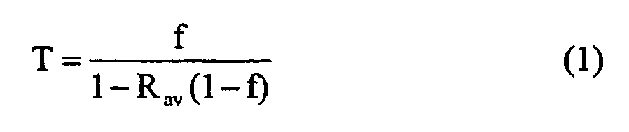
- Thereby, Rav denotes the averaged internal reflectivity Rav of the non-exit part of the light engine's inner wall surface according to

wherein
denotes the fraction of the internally reflecting light engine surface area Aengine - Aexit that is covered withLED elements 13. - The above equations do not assume any specific shape of the internal light engine wall. On the other hand, the series expansion in Equation (1) only holds for small aperture fractions f. In the extreme case of a light engine comprising a single flat light-emitting surface, one has a maximum f = 0.5 and, by definition, T = 1 since no reflecting surfaces are in the way of the emitting light sources. In this case, Equation (1) erroneously predicts a T < 1 but the error is still not substantial as long as Rav > 0.90, which can readily be accomplished.
- For realistic light engines, an upper limit f ≈ 0.3 - 0.4 should preferably be maintained, but the concept of a light engine according to the invention is obviously more interesting for much smaller values of f. For example a light engine embodied as a square cube that is open on only one of its six sides possesses an aperture fraction f = 0.17. Smaller values for the aperture fraction f can be easily obtained by making the cube more rectangular while keeping only one of its two small sides open. In a preferred embodiment of the invention, the aperture fraction f should be ≤ 0.15, more preferably ≤ 0.1. For example, a
light engine 1 according toFigure 1 with a diameter of 2 cm, a chamber length of 3 cm and an aperture diameter of 1 cm has an aperture fraction f = 0.03. - In case RLED = Rwall = Rav = 1, no light losses are present and one obtains T = 1 according to Equation (1) for any arbitrarily small aperture fraction f. This would theoretically allow the creation of extremely high brightness levels when f→ 0. In reality, however, this is impossible since optical light losses can never be fully avoided.
- It is therefore also of interest to derive an equation for the obtainable brightness at the
aperture exit port 7 of thelight engine 1 as a function of the system parameters. The brightness ratio B, denoting the brightness Bexit at the aperture exit port 7 (assuming that nocollimating element 8 is present) normalised with respect to the brightness level BLED of an individual LED dieelement 13, follows from
which is valid when both the LED dies 13 and theaperture exit port 7 emit non-collimated light (i.e. Lambertian light with θc = 90°). - In addition, it is instructive to derive a relation for a second brightness ratio L(θc), also called 'brightness concentration factor' in the following, with

which denotes the ratio of the brightness Bexit(θc) of the light-emitting exit surface (which may be the projected light-emitting exit surface Acol of the collimating element 8) to the screen-averaged brightness Bscreen(θc) of an imaginary flat screen of surface area Ascreen = Aengine - Aexit whereuponLED elements 13 are mounted at a packing density θLED. Here, light is assumed to be emitted as a collimated beam that is angularly bounded within a collimation half-angle θc with respect to the propagation direction of the beam. For non-collimated light, one has θc = 90°. - Knowledge of the brightness concentration factor L(θc) indicates whether or not a net light concentration has been achieved by packing NLED dies together inside a
light engine 1 at a surface packing density θLED in comparison with the simpler situation wherein the NLED dies are simply mounted on a flat light emitting screen at the same surface packing density. A value L(θc) > 1 indicates a relative light (brightness) concentration and a value L(θc) < 1 indicates a relative light (brightness) dilution. Evidently, a value of L(θc) as large as is practically possible, and certainly higher than 1, is generally desirable. - In case the
light engine 1 is made to emit 2D-collimated light, as shown infigure 1 , the relevant exit port surface area becomes that of the projected output surface Acol of thecollimating element 8 mounted on theexit port 7 of thelight engine 1. Following the etendue law, for a given collimation half-angle θc, the minimum required output surface area Acol of thecollimating element 8 relates to the output area Aexit of theaperture 7 of thelight engine 1 infigure 1 according to
and thus indicates an inevitable enlargement of the emitting surface Acol at decreasing θc. - The screen-averaged brightness level Bscreen(θc) relates to BLED(θc) according to

- In the embodiment of the
light engine 1 according toFigure 1 , the individual LED elements are provided with a collimating element in the form of pyramidaloutcoupling elements 15. Therefore, the apparent light emitting surface area of an individual LED also increases but these can be directly accommodated on the mounting screen (the imaginary flat screen of surface area Ascreen defined above for derivation of equation (4)) without enlarging the screen as long as the LED packing density constraint
on the flat mounting screen is satisfied. The screen surface area Ascreen can then be taken to be independent of θc. - From the above, and bearing in mind that Bexit in Equation (4) denotes the brightness Bcol at the light output surface of the
collimating element 8 mounted on theaperture opening 7 of thelight engine 1 as soon as θc < 90°, it follows that L(θc) can be obtained from:

- For the special case θc = 90° (Lambertian light)
Figure 11 shows calculated values for the transmission T and the brightness ratio B as a function of the aperture fraction f at a packing density θLED = 0.05 and at reflectivities Rwall = 0.98 and RLED = 0.50 which corresponds to realistic conditions. - It is clear from
Figure 11 that, at decreasing aperture fraction f, the attainable brightness ratio B at the exit port increases, albeit at a significantly decreasing lumen output, which is proportional to the transmitted fraction T of the internally produced light that leaves the light engine. Because lumen flux and brightness exhibit opposite trends in their relationship with the aperture fraction f, it makes sense to define a quality parameter Q according to
- In
Figure 11 the quality parameter Q is also plotted as a function of the aperture fraction f. From this plot it becomes apparent that Q goes through a maximum at an optimum aperture fraction fopt. Values for fopt follow from
with Rav given by Equation (2). - However, Q does not strongly depend on the aperture fraction f near f = fopt. In case a high T is more important than a high B (for example when a general lighting application is concerned), one is advised to choose a value f > fopt. The reverse is true when a high B is more important than a high T.
-
Figure 12 shows calculations of the quality parameter Q factor as a function of the aperture fraction f for various values of RLED and Rwall at a packing density θLED = 0.05 and for θc = 90°. (I: Rwall = 0.98 and RLED = 0.7; II: Rwall = 0.98 and RLED = 0.5; III: Rwall = 0.96 and RLED = 0.5). For aperture fractions around fopt, the quality parameter Q drops noticeably, i.e. the curve flattens out, if the reflectivities RLED and Rwall decrease. - Furthermore,
Figure 13 shows calculations of the quality parameter Q as a function of the aperture fraction f for various values θLED at constant Rwall = 0.98 and RLED = 0.5 and for θc = 90°. As can be seen, the quality parameter Q increases over the entire range of f with increasing packing density θLED. -
Figures 14 ,15 and 16 show calculations for the light concentration factor L(θc) at realistic reflectivities Rwall = 0.98 and RLED = 0.5 for various values of the aperture fraction f (inFigure 14 with a constant packing density θLED = 0.05) and for various values θLED (inFigure 15 with a constant aperture fraction f = 0.05 and inFigure 16 with a constant aperture fraction f = 0.1). In all figures the lines are drawn subject to the constraint according to Equation (7). - It is evident that, at least for θc = 60° (general lighting applications), use of a light engine according to the invention allows a significant brightness concentration to be accomplished with a numerical value up to a
factor 5 at 80% lumen output (i.e. T = 0.8). Also, higher light concentration factors L are achievable by reducing the aperture fraction f but at the cost of a reduced lumen efficiency. - Taking for granted that Rall and RLED are always chosen as high as practically possible, it is primarily the packing density θLED of the LED elements on the inner wall that affects the performance as a function of the aperture fraction f. A compromise will always have to be sought between brightness on the one hand and lumen efficiency on the other hand. Also the total required lumen output must be considered, whereby the size of the light engine is directly proportional to the total lumen output.
- In case a high lumen efficiency is most important, it is advisable to choose the aperture fraction f ≈ 0.10 - 0.12 at a low θLED ≈ 0.01. This allows for T ≈ 0.8 and B ≈ 0.07 which, at θc = 90°, is still seven times brighter than the screen-averaged brightness of the mounting wall. The brightness concentration factor L(θc) decreases at decreasing θc but remains substantial down to θc = 40°.
- In case a high brightness is most important, it is advisable to choose a higher LED packing density θLED ≈ 0.05, or even more if practicable. To raise the maximum attainable LED packing density, cooling of the LED elements should be provided, for example, by means of a matching refractive index cooling liquid as proposed above. At f ≈ 0.1, one has a smaller T = 0.65 but a higher brightness ratio B = 0.3, which, at θc = 90°, is still six times brighter than the screen-averaged brightness B = θLED of the mounting wall. The brightness can be further increased by decreasing the aperture fraction f down to, for example, f = 0.05. At f ≈ 0.1, the quality parameter Q significantly improves at increasing θLED. To obtain most benefit from the light engine according to the invention, it is therefore of great interest to increase θLED up to levels at and beyond θLED = 0.10
- Although the present invention has been disclosed in the form of preferred embodiments and variations thereon, it will be understood that numerous additional modifications and variations could be made thereto without departing from the scope of the invention. For the sake of clarity, it is also to be understood that the use of "a" or "an" throughout this application does not exclude a plurality, and "comprising" does not exclude other steps or elements.
Claims (14)
- Light engine (1, 2, 3, 4, 5) comprising a chamber (6) with at least one aperture (7) and a number of LED elements (13) positioned inside this chamber, wherein effectively all inner surfaces of the chamber (6) are realized as high-reflective surfaces (20) which are essentially non-absorbing towards light within a desired wavelength region and the high-reflective surfaces (20) are realized by a diffuse-reflective material (12, 18) distributed over the inside surface of the chamber walls (10, 10'),
characterized in that the diffuse-reflective material (12) is enclosed between a transparent covering plate (11, 11') and the inside surface of the chamber walls (10, 10'). - A light engine according to claim 1, comprising outcoupling means (15, 15', 16, 17, 19) for enhancing outcoupling of the light emitted by the LED elements (13) into the chamber (6).
- A light engine according to claim 1 or 2, wherein the diffuse-reflective material (12) comprises a reflective dry powder (12).
- A light engine according to claim 2, wherein the transparent covering plate (11) covers the LED elements (13), and the outcoupling means (15, 15') comprise a number of transparent outcoupling elements (15, 15') each of which extends from a light emitting surface of an associated LED element (13) to the transparent covering plate (11).
- A light engine according to claim 4, wherein the transparent outcoupling elements (15) have a cross section which is wider at an interface between the outcoupling element (15) and the transparent covering plate (11) than at an interface between the outcoupling element (15) and the associated LED element (13).
- A light engine according to any of claim 2 to 5, wherein the outcoupling means (19) comprise transparent domes (19) each of which is optically connected to a light emitting surface of an associated LED element.
- A light engine according to claim 6, wherein the domes (19) protrude through holes (22) in a covering plate (11', 21) covering the chamber wall (10) on which the LED elements are mounted.
- A light engine according to any of the claims 1 to 7, where the reflective material (12) distributed over the inside surface of the chamber walls (10, 10') comprises a light converting substance.
- A light engine according to any of the preceding claims where LED elements of different wavelength characteristics are positioned inside the chamber.
- A light engine according to any of the preceding claims comprising a light collimating element (8) positioned at the aperture (7) of the chamber (6).
- A light engine according to any of the preceding claims, wherein the chamber (6) is filled with a material (22) which has a refractive index that approaches or, preferably, matches the refractive index of the transparent covering plate (11, 11') and/or of the outcoupling means (15, 15', 19) and/or of the collimating element (8) and/or of the LED elements (13).
- A light engine according to claim 11, wherein the material (22) is a liquid material that is also used for the front-end cooling of the LED elements (13).
- A light engine according to any of the preceding claims, wherein an aperture fraction (f) defmed by the ratio of a surface area (Aexit) of the aperture (7) to a total interior surface area (Aengine) of the light engine ((1, 2, 3, 4, 5), which includes the surface area (Aexit) of the aperture (7), is preferably ≤ 0.15, more preferably ≤ 0.1.
- Automotive light system enclosing a light engine (1, 2, 3, 4, 5) according to any of the preceding claims.
Priority Applications (1)
| Application Number | Priority Date | Filing Date | Title |
|---|---|---|---|
| EP05773347A EP1776544B1 (en) | 2004-08-06 | 2005-08-02 | Light engine |
Applications Claiming Priority (3)
| Application Number | Priority Date | Filing Date | Title |
|---|---|---|---|
| EP04103783 | 2004-08-06 | ||
| EP05773347A EP1776544B1 (en) | 2004-08-06 | 2005-08-02 | Light engine |
| PCT/IB2005/052583 WO2006016324A1 (en) | 2004-08-06 | 2005-08-02 | Light engine |
Publications (2)
| Publication Number | Publication Date |
|---|---|
| EP1776544A1 EP1776544A1 (en) | 2007-04-25 |
| EP1776544B1 true EP1776544B1 (en) | 2010-01-20 |
Family
ID=35170024
Family Applications (1)
| Application Number | Title | Priority Date | Filing Date |
|---|---|---|---|
| EP05773347A Expired - Lifetime EP1776544B1 (en) | 2004-08-06 | 2005-08-02 | Light engine |
Country Status (9)
| Country | Link |
|---|---|
| US (1) | US7722211B2 (en) |
| EP (1) | EP1776544B1 (en) |
| JP (1) | JP4829230B2 (en) |
| KR (1) | KR101214135B1 (en) |
| CN (1) | CN100510512C (en) |
| AT (1) | ATE456000T1 (en) |
| DE (1) | DE602005019055D1 (en) |
| TW (1) | TWI343463B (en) |
| WO (1) | WO2006016324A1 (en) |
Cited By (1)
| Publication number | Priority date | Publication date | Assignee | Title |
|---|---|---|---|---|
| US20220016304A1 (en) * | 2020-07-17 | 2022-01-20 | 12180235 Canada Ltd. | Apparatus for reflecting an incident ray of electromagnetic radiation |
Families Citing this family (94)
| Publication number | Priority date | Publication date | Assignee | Title |
|---|---|---|---|---|
| US20020176259A1 (en) | 1999-11-18 | 2002-11-28 | Ducharme Alfred D. | Systems and methods for converting illumination |
| US8215815B2 (en) * | 2005-06-07 | 2012-07-10 | Oree, Inc. | Illumination apparatus and methods of forming the same |
| WO2006131924A2 (en) * | 2005-06-07 | 2006-12-14 | Oree, Advanced Illumination Solutions Inc. | Illumination apparatus |
| US8272758B2 (en) | 2005-06-07 | 2012-09-25 | Oree, Inc. | Illumination apparatus and methods of forming the same |
| US20080007936A1 (en) * | 2006-07-05 | 2008-01-10 | Jie Liu | Organic illumination source and method for controlled illumination |
| US20080025040A1 (en) * | 2006-07-25 | 2008-01-31 | Swantner Michael J | LED light engine |
| KR101394007B1 (en) * | 2007-09-11 | 2014-05-13 | 엘지이노텍 주식회사 | Light unit and display apparatus having thereof |
| US8172447B2 (en) | 2007-12-19 | 2012-05-08 | Oree, Inc. | Discrete lighting elements and planar assembly thereof |
| US20090161369A1 (en) * | 2007-12-19 | 2009-06-25 | Keren Regev | Waveguide sheet and methods for manufacturing the same |
| EP2260341A2 (en) * | 2008-03-05 | 2010-12-15 | Oree, Advanced Illumination Solutions INC. | Illumination apparatus and methods of forming the same |
| US7845825B2 (en) * | 2009-12-02 | 2010-12-07 | Abl Ip Holding Llc | Light fixture using near UV solid state device and remote semiconductor nanophosphors to produce white light |
| US8172424B2 (en) * | 2009-05-01 | 2012-05-08 | Abl Ip Holding Llc | Heat sinking and flexible circuit board, for solid state light fixture utilizing an optical cavity |
| US7980728B2 (en) * | 2008-05-27 | 2011-07-19 | Abl Ip Holding Llc | Solid state lighting using light transmissive solid in or forming optical integrating volume |
| US8021008B2 (en) * | 2008-05-27 | 2011-09-20 | Abl Ip Holding Llc | Solid state lighting using quantum dots in a liquid |
| US8028537B2 (en) * | 2009-05-01 | 2011-10-04 | Abl Ip Holding Llc | Heat sinking and flexible circuit board, for solid state light fixture utilizing an optical cavity |
| US8212469B2 (en) | 2010-02-01 | 2012-07-03 | Abl Ip Holding Llc | Lamp using solid state source and doped semiconductor nanophosphor |
| US8690384B2 (en) * | 2008-06-06 | 2014-04-08 | Relume Technologies, Inc. | Integral heat sink and housing light emitting diode assembly |
| US8297786B2 (en) * | 2008-07-10 | 2012-10-30 | Oree, Inc. | Slim waveguide coupling apparatus and method |
| US8301002B2 (en) | 2008-07-10 | 2012-10-30 | Oree, Inc. | Slim waveguide coupling apparatus and method |
| US7946735B2 (en) * | 2008-08-22 | 2011-05-24 | Joseph Chou | LED lighting apparatus having heat dissipating frame |
| CN102187486B (en) * | 2008-10-17 | 2014-01-15 | 皇家飞利浦电子股份有限公司 | Light emitting device |
| US8408724B2 (en) * | 2008-12-26 | 2013-04-02 | Toshiba Lighting & Technology Corporation | Light source module and lighting apparatus |
| US8624527B1 (en) | 2009-03-27 | 2014-01-07 | Oree, Inc. | Independently controllable illumination device |
| US8328406B2 (en) | 2009-05-13 | 2012-12-11 | Oree, Inc. | Low-profile illumination device |
| US8007129B2 (en) * | 2009-05-22 | 2011-08-30 | Chen-Sheng Yang | LED-based christmas light string assembly with parallel-wired lighting units |
| WO2010150202A2 (en) | 2009-06-24 | 2010-12-29 | Oree, Advanced Illumination Solutions Inc. | Illumination apparatus with high conversion efficiency and methods of forming the same |
| WO2011019666A1 (en) * | 2009-08-12 | 2011-02-17 | Alcon Research, Ltd. | Ophthalmic endoillumination with light collector for white phosphor |
| US20110110079A1 (en) * | 2009-11-11 | 2011-05-12 | Cheng-Chao Jong | Light guide illumination device |
| US8118454B2 (en) | 2009-12-02 | 2012-02-21 | Abl Ip Holding Llc | Solid state lighting system with optic providing occluded remote phosphor |
| US9163802B2 (en) * | 2009-12-02 | 2015-10-20 | Abl Ip Holding Llc | Lighting fixtures using solid state device and remote phosphors to produce white light |
| US8217406B2 (en) * | 2009-12-02 | 2012-07-10 | Abl Ip Holding Llc | Solid state light emitter with pumped nanophosphors for producing high CRI white light |
| US20110127555A1 (en) * | 2009-12-02 | 2011-06-02 | Renaissance Lighting, Inc. | Solid state light emitter with phosphors dispersed in a liquid or gas for producing high cri white light |
| DE102010001007B4 (en) * | 2010-01-19 | 2013-01-03 | Osram Ag | Luminaire for illuminating a target area by means of backward reflection of light from a light-emitting diode module on a reflector |
| US9719012B2 (en) * | 2010-02-01 | 2017-08-01 | Abl Ip Holding Llc | Tubular lighting products using solid state source and semiconductor nanophosphor, E.G. for florescent tube replacement |
| US8517550B2 (en) | 2010-02-15 | 2013-08-27 | Abl Ip Holding Llc | Phosphor-centric control of color of light |
| US8820950B2 (en) * | 2010-03-12 | 2014-09-02 | Toshiba Lighting & Technology Corporation | Light emitting device and illumination apparatus |
| US8322884B2 (en) | 2010-03-31 | 2012-12-04 | Abl Ip Holding Llc | Solid state lighting with selective matching of index of refraction |
| US8089207B2 (en) * | 2010-05-10 | 2012-01-03 | Abl Ip Holding Llc | Lighting using solid state device and phosphors to produce light approximating a black body radiation spectrum |
| US20130063964A1 (en) * | 2010-05-12 | 2013-03-14 | Oree, Inc. | Illumination Apparatus with High Conversion Efficiency and Methods of Forming the Same |
| US9033530B2 (en) | 2010-06-22 | 2015-05-19 | Osram Gmbh | Phosphor device and lighting apparatus comprising the same |
| US8568009B2 (en) | 2010-08-20 | 2013-10-29 | Dicon Fiberoptics Inc. | Compact high brightness LED aquarium light apparatus, using an extended point source LED array with light emitting diodes |
| US8523385B2 (en) * | 2010-08-20 | 2013-09-03 | DiCon Fibêroptics Inc. | Compact high brightness LED grow light apparatus, using an extended point source LED array with light emitting diodes |
| US8217557B2 (en) * | 2010-08-31 | 2012-07-10 | Micron Technology, Inc. | Solid state lights with thermosiphon liquid cooling structures and methods |
| DE112010005320T5 (en) * | 2010-11-09 | 2012-12-20 | Osram Ag | Phosphor arrangement with phosphor element and optical system |
| US20120140463A1 (en) * | 2010-12-07 | 2012-06-07 | Kinzer David J | Led profile luminaire |
| EP2466375B1 (en) * | 2010-12-17 | 2019-12-25 | Maxell, Ltd. | Light Source Apparatus |
| KR101771557B1 (en) | 2011-01-05 | 2017-08-25 | 엘지전자 주식회사 | Display Apparatus |
| WO2012103508A2 (en) * | 2011-01-29 | 2012-08-02 | Kim Gerald Ho | Silicon-based cooling package for light-emitting devices |
| US9570666B2 (en) * | 2011-01-29 | 2017-02-14 | Gerald Ho Kim | Silicon-based cooling package for light-emitting devices |
| US8226274B2 (en) * | 2011-03-01 | 2012-07-24 | Switch Bulb Company, Inc. | Liquid displacer in LED bulbs |
| WO2012136572A1 (en) * | 2011-04-05 | 2012-10-11 | Valitutti Pierfranco | Light source for testing a photovoltaic panel or cell |
| US8596815B2 (en) | 2011-04-15 | 2013-12-03 | Dicon Fiberoptics Inc. | Multiple wavelength LED array illuminator for fluorescence microscopy |
| US9797589B2 (en) | 2011-05-09 | 2017-10-24 | Cree, Inc. | High efficiency LED lamp |
| US10094548B2 (en) | 2011-05-09 | 2018-10-09 | Cree, Inc. | High efficiency LED lamp |
| US8833980B2 (en) | 2011-05-09 | 2014-09-16 | Cree, Inc. | High efficiency LED lamp |
| US8979316B2 (en) | 2011-05-11 | 2015-03-17 | Dicon Fiberoptics Inc. | Zoom spotlight using LED array |
| KR101807664B1 (en) * | 2011-05-30 | 2017-12-11 | 삼성전자 주식회사 | Omnidirectional light emitting device lamp |
| US9447931B2 (en) | 2011-06-24 | 2016-09-20 | Koninklijke Philips N.V. | LED-based lighting unit with optical component for mixing light output from a plurality of LEDs |
| CN102322575A (en) * | 2011-08-31 | 2012-01-18 | 广东威创视讯科技股份有限公司 | Device for obtaining mixed light type point light source |
| US8803414B2 (en) * | 2011-09-02 | 2014-08-12 | Cree, Inc. | Lighting device |
| US8591072B2 (en) | 2011-11-16 | 2013-11-26 | Oree, Inc. | Illumination apparatus confining light by total internal reflection and methods of forming the same |
| US9360192B2 (en) | 2011-11-17 | 2016-06-07 | Osram Gmbh | LED illuminating device |
| EP2798265B1 (en) * | 2011-12-27 | 2017-09-13 | Philips Lighting Holding B.V. | Reflector device and lighting device comprising such a reflector device |
| KR20130078959A (en) * | 2012-01-02 | 2013-07-10 | 삼성전자주식회사 | A light source module and a lighting device including the same |
| DE202012000325U1 (en) | 2012-01-13 | 2012-04-26 | Osram Ag | LED module with improved cooling |
| CN103239202A (en) * | 2012-02-01 | 2013-08-14 | 恒景科技股份有限公司 | Endoscope with integrated light source |
| DE102012205571A1 (en) * | 2012-04-04 | 2013-10-10 | Osram Gmbh | ILLUMINATION DEVICE |
| TWI476353B (en) * | 2012-04-13 | 2015-03-11 | Radiant Opto Electronics Corp | Lighting module |
| US9239133B2 (en) | 2012-05-24 | 2016-01-19 | Excelitas Canada, Inc. | High brightness solid state illumination system for fluorescence imaging and analysis |
| US9952442B2 (en) | 2012-05-24 | 2018-04-24 | Excelitas Canada, Inc. | High brightness solid state illumination system for fluorescence imaging and analysis |
| US20130314893A1 (en) * | 2012-05-24 | 2013-11-28 | Lumen Dynamics Group Inc. | High brightness illumination system and wavelength conversion module for microscopy and other applications |
| DE102012209131A1 (en) * | 2012-05-31 | 2013-12-05 | Osram Gmbh | LIGHTING DEVICE WITH SEMICONDUCTOR LIGHT SOURCES AND COMMON DIFFUSER |
| US9857519B2 (en) | 2012-07-03 | 2018-01-02 | Oree Advanced Illumination Solutions Ltd. | Planar remote phosphor illumination apparatus |
| TW201405048A (en) * | 2012-07-19 | 2014-02-01 | 瓦維安股份有限公司 | Phosphor-based luminaire for projection displays |
| US20150138779A1 (en) * | 2012-08-10 | 2015-05-21 | Goldeneye, Inc. | Lightweight low profile solid state panel light source |
| CN104937336A (en) * | 2012-09-18 | 2015-09-23 | 维文公司 | Illuminator system comprising a parabolic reflector with two reflections for recycling light |
| CA2803835A1 (en) * | 2013-01-15 | 2014-07-15 | George Uh-Schu Liau | A light character producer and its extended application in photovoltaics |
| US9133990B2 (en) | 2013-01-31 | 2015-09-15 | Dicon Fiberoptics Inc. | LED illuminator apparatus, using multiple luminescent materials dispensed onto an array of LEDs, for improved color rendering, color mixing, and color temperature control |
| US9235039B2 (en) | 2013-02-15 | 2016-01-12 | Dicon Fiberoptics Inc. | Broad-spectrum illuminator for microscopy applications, using the emissions of luminescent materials |
| US8933478B2 (en) | 2013-02-19 | 2015-01-13 | Cooledge Lighting Inc. | Engineered-phosphor LED packages and related methods |
| US8754435B1 (en) | 2013-02-19 | 2014-06-17 | Cooledge Lighting Inc. | Engineered-phosphor LED package and related methods |
| US10788678B2 (en) | 2013-05-17 | 2020-09-29 | Excelitas Canada, Inc. | High brightness solid state illumination system for fluorescence imaging and analysis |
| DE202013005254U1 (en) | 2013-06-10 | 2013-07-01 | Anh Minh Do | LED spotlight with water cooling system |
| EP2846085B1 (en) | 2013-09-09 | 2017-03-01 | OSRAM GmbH | A lighting device and corresponding method |
| JP6476592B2 (en) * | 2014-05-22 | 2019-03-06 | 信越化学工業株式会社 | Wavelength conversion member |
| EP3170203B1 (en) | 2014-07-18 | 2020-05-06 | Lumileds Holding B.V. | Light emitting diodes and reflector |
| JP6583813B2 (en) * | 2015-07-30 | 2019-10-02 | パナソニックIpマネジメント株式会社 | Light source and illumination device using the light source |
| US9548255B1 (en) * | 2015-08-17 | 2017-01-17 | Freescale Semiconductor, Inc. | IC package having non-horizontal die pad and flexible substrate therefor |
| US9478587B1 (en) | 2015-12-22 | 2016-10-25 | Dicon Fiberoptics Inc. | Multi-layer circuit board for mounting multi-color LED chips into a uniform light emitter |
| KR102682009B1 (en) * | 2018-11-13 | 2024-07-08 | 삼성전자주식회사 | Light emitting module and light apparatus for car including the same |
| US11773016B2 (en) | 2018-12-14 | 2023-10-03 | Corning Incorporated | Diffuse reflector and methods of use |
| JP7756637B2 (en) * | 2019-10-18 | 2025-10-20 | シグニファイ ホールディング ビー ヴィ | Light emitting device having a mixing chamber |
| CN115117100B (en) * | 2021-03-17 | 2025-10-03 | 联合微电子中心有限责任公司 | Image sensor and method for preparing isolated scattering structure for image sensor |
| US12344552B2 (en) | 2021-10-08 | 2025-07-01 | Corning Incorporated | Spacer and methods for optimizing optical fiber curing process |
Family Cites Families (29)
| Publication number | Priority date | Publication date | Assignee | Title |
|---|---|---|---|---|
| FR2471014A1 (en) | 1979-11-28 | 1981-06-12 | Radiotechnique Compelec | ELECTROLUMINESCENT DIODE DISPLAY DEVICE |
| FR2472135A1 (en) * | 1979-12-20 | 1981-06-26 | Cibie Projecteurs | PROJECTOR, IN PARTICULAR FOR MOTOR VEHICLES |
| US4935665A (en) * | 1987-12-24 | 1990-06-19 | Mitsubishi Cable Industries Ltd. | Light emitting diode lamp |
| JPH0368705U (en) * | 1989-07-26 | 1991-07-08 | ||
| JPH0381941U (en) * | 1989-09-19 | 1991-08-21 | ||
| DE4040020C2 (en) * | 1990-12-14 | 1999-07-15 | Bosch Gmbh Robert | Lighting device for vehicles |
| JPH08203305A (en) * | 1995-01-25 | 1996-08-09 | Makino:Kk | Decorative illumination plate |
| AUPN898196A0 (en) * | 1996-03-28 | 1996-04-26 | Nulite Systems International Pty Ltd | Apparatus and method for polymerising dental photopolymerisable compositions |
| US5890794A (en) * | 1996-04-03 | 1999-04-06 | Abtahi; Homayoon | Lighting units |
| TW408497B (en) | 1997-11-25 | 2000-10-11 | Matsushita Electric Works Ltd | LED illuminating apparatus |
| JPH11340378A (en) | 1998-05-22 | 1999-12-10 | Sanken Electric Co Ltd | Method for manufacturing semiconductor light emitting device |
| JP4366016B2 (en) * | 1998-09-28 | 2009-11-18 | コーニンクレッカ フィリップス エレクトロニクス エヌ ヴィ | Lighting device |
| JP2002532893A (en) | 1998-12-17 | 2002-10-02 | コーニンクレッカ フィリップス エレクトロニクス エヌ ヴィ | Light engine |
| JP3149402B2 (en) | 1999-02-09 | 2001-03-26 | 株式会社ナカニシ | Medical lighting equipment |
| JP3068705U (en) * | 1999-11-02 | 2000-05-16 | 松生 小野 | Surface light source plate for liquid crystal display |
| US6422718B1 (en) * | 1999-11-18 | 2002-07-23 | Integrated Systems Technologies Limited | Non-imaging light source for uniform illumination applications |
| JP4445082B2 (en) * | 1999-12-07 | 2010-04-07 | ラディアント リサーチ リミテッド | Illumination device |
| DE10016714C2 (en) | 2000-04-04 | 2003-03-27 | Vishay Semiconductor Gmbh | Radiation-emitting device |
| JP2001325809A (en) * | 2000-05-15 | 2001-11-22 | Sanaa Electronics Kk | Light bulb type light emitting diode |
| JP4371551B2 (en) * | 2000-08-02 | 2009-11-25 | 市光工業株式会社 | Vehicle lighting |
| US6547423B2 (en) * | 2000-12-22 | 2003-04-15 | Koninklijke Phillips Electronics N.V. | LED collimation optics with improved performance and reduced size |
| JP2002280617A (en) * | 2001-03-19 | 2002-09-27 | Matsushita Electric Ind Co Ltd | Lighting equipment |
| US7152996B2 (en) | 2001-04-27 | 2006-12-26 | Altman Stage Lighting Co., Inc. | Diode lighting system |
| GB0112867D0 (en) | 2001-05-26 | 2001-07-18 | Enfis Ltd | Light emitting apparatus unit |
| DE10142541B9 (en) | 2001-08-30 | 2014-05-28 | Osram Opto Semiconductors Gmbh | Electroluminescent body |
| JP2004210921A (en) | 2002-12-27 | 2004-07-29 | Nichia Chem Ind Ltd | Oxynitride phosphor, method of manufacturing the same, and light emitting device using the same |
| US6995355B2 (en) * | 2003-06-23 | 2006-02-07 | Advanced Optical Technologies, Llc | Optical integrating chamber lighting using multiple color sources |
| US7145125B2 (en) * | 2003-06-23 | 2006-12-05 | Advanced Optical Technologies, Llc | Integrating chamber cone light using LED sources |
| US7521667B2 (en) * | 2003-06-23 | 2009-04-21 | Advanced Optical Technologies, Llc | Intelligent solid state lighting |
-
2005
- 2005-08-02 DE DE602005019055T patent/DE602005019055D1/en not_active Expired - Lifetime
- 2005-08-02 US US11/573,051 patent/US7722211B2/en not_active Expired - Lifetime
- 2005-08-02 AT AT05773347T patent/ATE456000T1/en not_active IP Right Cessation
- 2005-08-02 WO PCT/IB2005/052583 patent/WO2006016324A1/en not_active Ceased
- 2005-08-02 JP JP2007524453A patent/JP4829230B2/en not_active Expired - Lifetime
- 2005-08-02 KR KR1020077005239A patent/KR101214135B1/en not_active Expired - Lifetime
- 2005-08-02 EP EP05773347A patent/EP1776544B1/en not_active Expired - Lifetime
- 2005-08-02 CN CNB2005800266466A patent/CN100510512C/en not_active Expired - Lifetime
- 2005-08-03 TW TW094126390A patent/TWI343463B/en not_active IP Right Cessation
Cited By (1)
| Publication number | Priority date | Publication date | Assignee | Title |
|---|---|---|---|---|
| US20220016304A1 (en) * | 2020-07-17 | 2022-01-20 | 12180235 Canada Ltd. | Apparatus for reflecting an incident ray of electromagnetic radiation |
Also Published As
| Publication number | Publication date |
|---|---|
| KR101214135B1 (en) | 2012-12-21 |
| US20080094835A1 (en) | 2008-04-24 |
| ATE456000T1 (en) | 2010-02-15 |
| DE602005019055D1 (en) | 2010-03-11 |
| US7722211B2 (en) | 2010-05-25 |
| CN1993581A (en) | 2007-07-04 |
| EP1776544A1 (en) | 2007-04-25 |
| TWI343463B (en) | 2011-06-11 |
| JP4829230B2 (en) | 2011-12-07 |
| WO2006016324A1 (en) | 2006-02-16 |
| CN100510512C (en) | 2009-07-08 |
| TW200617320A (en) | 2006-06-01 |
| JP2008509515A (en) | 2008-03-27 |
| KR20070044483A (en) | 2007-04-27 |
Similar Documents
| Publication | Publication Date | Title |
|---|---|---|
| US7722211B2 (en) | Light engine | |
| US20230135796A1 (en) | Light-Emitting Devices Providing Asymmetrical Propagation of Light | |
| KR101460484B1 (en) | Lighting system using multiple colored light-emitting sources and deffuser element | |
| EP1769193B1 (en) | High efficiency light source using solid-state emitter and down-conversion material | |
| JP5711147B2 (en) | Light source with LED, light guide and reflector | |
| US10677981B2 (en) | Large area light source and large area luminaire | |
| CN100521266C (en) | LED lamp system | |
| US20120140436A1 (en) | Solid-state lamps with light guide and photoluminescence material | |
| KR20110106919A (en) | An optical element having an LED, and a light source including the same | |
| CN104024728A (en) | Led-based light source with sharply defined field angle | |
| JP2006521667A (en) | Light projecting device and light projecting element | |
| KR20070058380A (en) | Optical manifold for light-emitting diodes | |
| JP2022524356A (en) | LED filament configuration | |
| US20110062454A1 (en) | Light emitting device having remotely located light scattering material | |
| CN101203965B (en) | Lighting device and method for lighting device design | |
| WO2014044513A1 (en) | Led illumination device |
Legal Events
| Date | Code | Title | Description |
|---|---|---|---|
| PUAI | Public reference made under article 153(3) epc to a published international application that has entered the european phase |
Free format text: ORIGINAL CODE: 0009012 |
|
| 17P | Request for examination filed |
Effective date: 20070306 |
|
| AK | Designated contracting states |
Kind code of ref document: A1 Designated state(s): AT BE BG CH CY CZ DE DK EE ES FI FR GB GR HU IE IS IT LI LT LU LV MC NL PL PT RO SE SI SK TR |
|
| DAX | Request for extension of the european patent (deleted) | ||
| 17Q | First examination report despatched |
Effective date: 20080624 |
|
| GRAP | Despatch of communication of intention to grant a patent |
Free format text: ORIGINAL CODE: EPIDOSNIGR1 |
|
| GRAS | Grant fee paid |
Free format text: ORIGINAL CODE: EPIDOSNIGR3 |
|
| GRAA | (expected) grant |
Free format text: ORIGINAL CODE: 0009210 |
|
| AK | Designated contracting states |
Kind code of ref document: B1 Designated state(s): AT BE BG CH CY CZ DE DK EE ES FI FR GB GR HU IE IS IT LI LT LU LV MC NL PL PT RO SE SI SK TR |
|
| REG | Reference to a national code |
Ref country code: GB Ref legal event code: FG4D |
|
| REG | Reference to a national code |
Ref country code: CH Ref legal event code: EP |
|
| REG | Reference to a national code |
Ref country code: IE Ref legal event code: FG4D |
|
| REF | Corresponds to: |
Ref document number: 602005019055 Country of ref document: DE Date of ref document: 20100311 Kind code of ref document: P |
|
| REG | Reference to a national code |
Ref country code: NL Ref legal event code: VDEP Effective date: 20100120 |
|
| LTIE | Lt: invalidation of european patent or patent extension |
Effective date: 20100120 |
|
| PG25 | Lapsed in a contracting state [announced via postgrant information from national office to epo] |
Ref country code: AT Free format text: LAPSE BECAUSE OF FAILURE TO SUBMIT A TRANSLATION OF THE DESCRIPTION OR TO PAY THE FEE WITHIN THE PRESCRIBED TIME-LIMIT Effective date: 20100120 |
|
| PG25 | Lapsed in a contracting state [announced via postgrant information from national office to epo] |
Ref country code: IS Free format text: LAPSE BECAUSE OF FAILURE TO SUBMIT A TRANSLATION OF THE DESCRIPTION OR TO PAY THE FEE WITHIN THE PRESCRIBED TIME-LIMIT Effective date: 20100520 Ref country code: NL Free format text: LAPSE BECAUSE OF FAILURE TO SUBMIT A TRANSLATION OF THE DESCRIPTION OR TO PAY THE FEE WITHIN THE PRESCRIBED TIME-LIMIT Effective date: 20100120 Ref country code: LT Free format text: LAPSE BECAUSE OF FAILURE TO SUBMIT A TRANSLATION OF THE DESCRIPTION OR TO PAY THE FEE WITHIN THE PRESCRIBED TIME-LIMIT Effective date: 20100120 Ref country code: PT Free format text: LAPSE BECAUSE OF FAILURE TO SUBMIT A TRANSLATION OF THE DESCRIPTION OR TO PAY THE FEE WITHIN THE PRESCRIBED TIME-LIMIT Effective date: 20100520 Ref country code: ES Free format text: LAPSE BECAUSE OF FAILURE TO SUBMIT A TRANSLATION OF THE DESCRIPTION OR TO PAY THE FEE WITHIN THE PRESCRIBED TIME-LIMIT Effective date: 20100501 |
|
| PG25 | Lapsed in a contracting state [announced via postgrant information from national office to epo] |
Ref country code: FI Free format text: LAPSE BECAUSE OF FAILURE TO SUBMIT A TRANSLATION OF THE DESCRIPTION OR TO PAY THE FEE WITHIN THE PRESCRIBED TIME-LIMIT Effective date: 20100120 Ref country code: SI Free format text: LAPSE BECAUSE OF FAILURE TO SUBMIT A TRANSLATION OF THE DESCRIPTION OR TO PAY THE FEE WITHIN THE PRESCRIBED TIME-LIMIT Effective date: 20100120 Ref country code: PL Free format text: LAPSE BECAUSE OF FAILURE TO SUBMIT A TRANSLATION OF THE DESCRIPTION OR TO PAY THE FEE WITHIN THE PRESCRIBED TIME-LIMIT Effective date: 20100120 Ref country code: LV Free format text: LAPSE BECAUSE OF FAILURE TO SUBMIT A TRANSLATION OF THE DESCRIPTION OR TO PAY THE FEE WITHIN THE PRESCRIBED TIME-LIMIT Effective date: 20100120 |
|
| PG25 | Lapsed in a contracting state [announced via postgrant information from national office to epo] |
Ref country code: BE Free format text: LAPSE BECAUSE OF FAILURE TO SUBMIT A TRANSLATION OF THE DESCRIPTION OR TO PAY THE FEE WITHIN THE PRESCRIBED TIME-LIMIT Effective date: 20100120 Ref country code: EE Free format text: LAPSE BECAUSE OF FAILURE TO SUBMIT A TRANSLATION OF THE DESCRIPTION OR TO PAY THE FEE WITHIN THE PRESCRIBED TIME-LIMIT Effective date: 20100120 Ref country code: CY Free format text: LAPSE BECAUSE OF FAILURE TO SUBMIT A TRANSLATION OF THE DESCRIPTION OR TO PAY THE FEE WITHIN THE PRESCRIBED TIME-LIMIT Effective date: 20100120 Ref country code: SE Free format text: LAPSE BECAUSE OF FAILURE TO SUBMIT A TRANSLATION OF THE DESCRIPTION OR TO PAY THE FEE WITHIN THE PRESCRIBED TIME-LIMIT Effective date: 20100120 Ref country code: RO Free format text: LAPSE BECAUSE OF FAILURE TO SUBMIT A TRANSLATION OF THE DESCRIPTION OR TO PAY THE FEE WITHIN THE PRESCRIBED TIME-LIMIT Effective date: 20100120 Ref country code: GR Free format text: LAPSE BECAUSE OF FAILURE TO SUBMIT A TRANSLATION OF THE DESCRIPTION OR TO PAY THE FEE WITHIN THE PRESCRIBED TIME-LIMIT Effective date: 20100421 |
|
| PLBE | No opposition filed within time limit |
Free format text: ORIGINAL CODE: 0009261 |
|
| STAA | Information on the status of an ep patent application or granted ep patent |
Free format text: STATUS: NO OPPOSITION FILED WITHIN TIME LIMIT |
|
| PG25 | Lapsed in a contracting state [announced via postgrant information from national office to epo] |
Ref country code: CZ Free format text: LAPSE BECAUSE OF FAILURE TO SUBMIT A TRANSLATION OF THE DESCRIPTION OR TO PAY THE FEE WITHIN THE PRESCRIBED TIME-LIMIT Effective date: 20100120 Ref country code: BG Free format text: LAPSE BECAUSE OF FAILURE TO SUBMIT A TRANSLATION OF THE DESCRIPTION OR TO PAY THE FEE WITHIN THE PRESCRIBED TIME-LIMIT Effective date: 20100420 Ref country code: SK Free format text: LAPSE BECAUSE OF FAILURE TO SUBMIT A TRANSLATION OF THE DESCRIPTION OR TO PAY THE FEE WITHIN THE PRESCRIBED TIME-LIMIT Effective date: 20100120 |
|
| 26N | No opposition filed |
Effective date: 20101021 |
|
| PG25 | Lapsed in a contracting state [announced via postgrant information from national office to epo] |
Ref country code: DK Free format text: LAPSE BECAUSE OF FAILURE TO SUBMIT A TRANSLATION OF THE DESCRIPTION OR TO PAY THE FEE WITHIN THE PRESCRIBED TIME-LIMIT Effective date: 20100120 |
|
| PG25 | Lapsed in a contracting state [announced via postgrant information from national office to epo] |
Ref country code: IT Free format text: LAPSE BECAUSE OF FAILURE TO SUBMIT A TRANSLATION OF THE DESCRIPTION OR TO PAY THE FEE WITHIN THE PRESCRIBED TIME-LIMIT Effective date: 20100120 Ref country code: MC Free format text: LAPSE BECAUSE OF NON-PAYMENT OF DUE FEES Effective date: 20100831 |
|
| REG | Reference to a national code |
Ref country code: CH Ref legal event code: PL |
|
| PG25 | Lapsed in a contracting state [announced via postgrant information from national office to epo] |
Ref country code: LI Free format text: LAPSE BECAUSE OF NON-PAYMENT OF DUE FEES Effective date: 20100831 Ref country code: CH Free format text: LAPSE BECAUSE OF NON-PAYMENT OF DUE FEES Effective date: 20100831 |
|
| PG25 | Lapsed in a contracting state [announced via postgrant information from national office to epo] |
Ref country code: IE Free format text: LAPSE BECAUSE OF NON-PAYMENT OF DUE FEES Effective date: 20100802 |
|
| PG25 | Lapsed in a contracting state [announced via postgrant information from national office to epo] |
Ref country code: LU Free format text: LAPSE BECAUSE OF NON-PAYMENT OF DUE FEES Effective date: 20100802 Ref country code: HU Free format text: LAPSE BECAUSE OF FAILURE TO SUBMIT A TRANSLATION OF THE DESCRIPTION OR TO PAY THE FEE WITHIN THE PRESCRIBED TIME-LIMIT Effective date: 20100721 |
|
| PG25 | Lapsed in a contracting state [announced via postgrant information from national office to epo] |
Ref country code: TR Free format text: LAPSE BECAUSE OF FAILURE TO SUBMIT A TRANSLATION OF THE DESCRIPTION OR TO PAY THE FEE WITHIN THE PRESCRIBED TIME-LIMIT Effective date: 20100120 |
|
| REG | Reference to a national code |
Ref country code: DE Ref legal event code: R082 Ref document number: 602005019055 Country of ref document: DE Representative=s name: MEISSNER, BOLTE & PARTNER GBR, DE |
|
| REG | Reference to a national code |
Ref country code: DE Ref legal event code: R082 Ref document number: 602005019055 Country of ref document: DE Representative=s name: MEISSNER BOLTE PATENTANWAELTE RECHTSANWAELTE P, DE Effective date: 20140328 Ref country code: DE Ref legal event code: R081 Ref document number: 602005019055 Country of ref document: DE Owner name: PHILIPS LIGHTING HOLDING B.V., NL Free format text: FORMER OWNER: KONINKLIJKE PHILIPS ELECTRONICS N.V., EINDHOVEN, NL Effective date: 20140328 Ref country code: DE Ref legal event code: R082 Ref document number: 602005019055 Country of ref document: DE Representative=s name: MEISSNER, BOLTE & PARTNER GBR, DE Effective date: 20140328 Ref country code: DE Ref legal event code: R081 Ref document number: 602005019055 Country of ref document: DE Owner name: KONINKLIJKE PHILIPS N.V., NL Free format text: FORMER OWNER: KONINKLIJKE PHILIPS ELECTRONICS N.V., EINDHOVEN, NL Effective date: 20140328 |
|
| REG | Reference to a national code |
Ref country code: FR Ref legal event code: CA Effective date: 20141126 Ref country code: FR Ref legal event code: CD Owner name: KONINKLIJKE PHILIPS ELECTRONICS N.V., NL Effective date: 20141126 |
|
| REG | Reference to a national code |
Ref country code: FR Ref legal event code: PLFP Year of fee payment: 12 |
|
| REG | Reference to a national code |
Ref country code: GB Ref legal event code: 732E Free format text: REGISTERED BETWEEN 20161006 AND 20161012 |
|
| REG | Reference to a national code |
Ref country code: DE Ref legal event code: R081 Ref document number: 602005019055 Country of ref document: DE Owner name: SIGNIFY HOLDING B.V., NL Free format text: FORMER OWNER: KONINKLIJKE PHILIPS N.V., EINDHOVEN, NL Ref country code: DE Ref legal event code: R082 Ref document number: 602005019055 Country of ref document: DE Representative=s name: MEISSNER BOLTE PATENTANWAELTE RECHTSANWAELTE P, DE Ref country code: DE Ref legal event code: R081 Ref document number: 602005019055 Country of ref document: DE Owner name: PHILIPS LIGHTING HOLDING B.V., NL Free format text: FORMER OWNER: KONINKLIJKE PHILIPS N.V., EINDHOVEN, NL |
|
| REG | Reference to a national code |
Ref country code: FR Ref legal event code: PLFP Year of fee payment: 13 |
|
| REG | Reference to a national code |
Ref country code: FR Ref legal event code: PLFP Year of fee payment: 14 |
|
| REG | Reference to a national code |
Ref country code: DE Ref legal event code: R082 Ref document number: 602005019055 Country of ref document: DE Representative=s name: MEISSNER BOLTE PATENTANWAELTE RECHTSANWAELTE P, DE Ref country code: DE Ref legal event code: R081 Ref document number: 602005019055 Country of ref document: DE Owner name: SIGNIFY HOLDING B.V., NL Free format text: FORMER OWNER: PHILIPS LIGHTING HOLDING B.V., EINDHOVEN, NL |
|
| P01 | Opt-out of the competence of the unified patent court (upc) registered |
Effective date: 20230421 |
|
| PGFP | Annual fee paid to national office [announced via postgrant information from national office to epo] |
Ref country code: GB Payment date: 20240827 Year of fee payment: 20 |
|
| PGFP | Annual fee paid to national office [announced via postgrant information from national office to epo] |
Ref country code: FR Payment date: 20240826 Year of fee payment: 20 |
|
| PGFP | Annual fee paid to national office [announced via postgrant information from national office to epo] |
Ref country code: DE Payment date: 20241029 Year of fee payment: 20 |
|
| REG | Reference to a national code |
Ref country code: DE Ref legal event code: R071 Ref document number: 602005019055 Country of ref document: DE |
|
| REG | Reference to a national code |
Ref country code: GB Ref legal event code: PE20 Expiry date: 20250801 |