EP1775733A1 - Method and device for handling a container with radioactive material - Google Patents
Method and device for handling a container with radioactive material Download PDFInfo
- Publication number
- EP1775733A1 EP1775733A1 EP05022433A EP05022433A EP1775733A1 EP 1775733 A1 EP1775733 A1 EP 1775733A1 EP 05022433 A EP05022433 A EP 05022433A EP 05022433 A EP05022433 A EP 05022433A EP 1775733 A1 EP1775733 A1 EP 1775733A1
- Authority
- EP
- European Patent Office
- Prior art keywords
- container
- handling device
- snap
- snap connecting
- connecting member
- Prior art date
- Legal status (The legal status is an assumption and is not a legal conclusion. Google has not performed a legal analysis and makes no representation as to the accuracy of the status listed.)
- Withdrawn
Links
- 238000000034 method Methods 0.000 title claims abstract description 20
- 239000012857 radioactive material Substances 0.000 title claims abstract description 19
- 230000005855 radiation Effects 0.000 claims abstract description 31
- 230000000694 effects Effects 0.000 claims abstract description 10
- 239000000463 material Substances 0.000 claims description 11
- 230000002093 peripheral effect Effects 0.000 claims description 4
- 238000005452 bending Methods 0.000 claims description 3
- 239000002775 capsule Substances 0.000 description 12
- 230000002285 radioactive effect Effects 0.000 description 4
- 208000024770 Thyroid neoplasm Diseases 0.000 description 2
- 238000013265 extended release Methods 0.000 description 2
- 238000005259 measurement Methods 0.000 description 2
- 201000002510 thyroid cancer Diseases 0.000 description 2
- PNDPGZBMCMUPRI-HVTJNCQCSA-N 10043-66-0 Chemical compound [131I][131I] PNDPGZBMCMUPRI-HVTJNCQCSA-N 0.000 description 1
- ZCYVEMRRCGMTRW-UHFFFAOYSA-N 7553-56-2 Chemical compound [I] ZCYVEMRRCGMTRW-UHFFFAOYSA-N 0.000 description 1
- 206010073306 Exposure to radiation Diseases 0.000 description 1
- 208000024799 Thyroid disease Diseases 0.000 description 1
- 230000005540 biological transmission Effects 0.000 description 1
- 230000006835 compression Effects 0.000 description 1
- 238000007906 compression Methods 0.000 description 1
- 238000002405 diagnostic procedure Methods 0.000 description 1
- 201000010099 disease Diseases 0.000 description 1
- 208000037265 diseases, disorders, signs and symptoms Diseases 0.000 description 1
- 238000003780 insertion Methods 0.000 description 1
- 230000037431 insertion Effects 0.000 description 1
- 229910052740 iodine Inorganic materials 0.000 description 1
- 239000011630 iodine Substances 0.000 description 1
- 230000002035 prolonged effect Effects 0.000 description 1
- FVAUCKIRQBBSSJ-LAIFMVDKSA-M sodium;iodine-131(1-) Chemical compound [Na+].[131I-] FVAUCKIRQBBSSJ-LAIFMVDKSA-M 0.000 description 1
- 230000001225 therapeutic effect Effects 0.000 description 1
- 210000001685 thyroid gland Anatomy 0.000 description 1
- WFKWXMTUELFFGS-UHFFFAOYSA-N tungsten Chemical compound [W] WFKWXMTUELFFGS-UHFFFAOYSA-N 0.000 description 1
- 229910052721 tungsten Inorganic materials 0.000 description 1
- 239000010937 tungsten Substances 0.000 description 1
Images


Classifications
-
- G—PHYSICS
- G21—NUCLEAR PHYSICS; NUCLEAR ENGINEERING
- G21F—PROTECTION AGAINST X-RADIATION, GAMMA RADIATION, CORPUSCULAR RADIATION OR PARTICLE BOMBARDMENT; TREATING RADIOACTIVELY CONTAMINATED MATERIAL; DECONTAMINATION ARRANGEMENTS THEREFOR
- G21F5/00—Transportable or portable shielded containers
- G21F5/06—Details of, or accessories to, the containers
- G21F5/14—Devices for handling containers or shipping-casks, e.g. transporting devices loading and unloading, filling of containers
-
- G—PHYSICS
- G21—NUCLEAR PHYSICS; NUCLEAR ENGINEERING
- G21F—PROTECTION AGAINST X-RADIATION, GAMMA RADIATION, CORPUSCULAR RADIATION OR PARTICLE BOMBARDMENT; TREATING RADIOACTIVELY CONTAMINATED MATERIAL; DECONTAMINATION ARRANGEMENTS THEREFOR
- G21F5/00—Transportable or portable shielded containers
- G21F5/015—Transportable or portable shielded containers for storing radioactive sources, e.g. source carriers for irradiation units; Radioisotope containers
Definitions
- the present invention relates to a method of handling a container with radioactive material that is stored in a radiation shielding enclosure.
- containers When handling containers that are filled with radioactive material, special care is required to avoid prolonged exposure to radiation.
- An example of such containers are plastic vials containing capsules of for instance iodine 131 that are used for therapeutic purposes, e.g. in oncology. These containers or vials are usually stored in radiation shielding enclosures, for instance thick walled cylinders made of lead or tungsten and closed by a lid of the same material.
- I-131 Sodium iodide (I-131), administered in the form of capsules, is used to treat patients with thyroid diseases: hyperthyroidia and thyroid cancer.
- thyroid diseases hyperthyroidia and thyroid cancer.
- I-131 radioactivity This defined amount depends for example on the type of disease, the amount of radioactive iodine that is taken up by the thyroid during a diagnostic procedure preceding the actual administration, the age of the patient, the radiation dose that the physician wants to deliver, etc.
- the capsules In order to achieve optimal patient care, it is important to measure the exact radioactive content of a I-131 capsule that is to be administered to the patient. This measurement may be performed in a suitable ionization chamber.
- the radioactivity of the capsules can be quite high (capsules of 7.4 GBq (200 mCi) are sometimes administered to patients with metastasized thyroid cancer), so the time that this amount of radioactivity is outside of its radiation shielded enclosure should be as short as possible in order to minimize the radiation dose to the hospital staff handling the capsules.
- the capsules should be kept at a sufficient distance from the hands of a person handling the material.
- the present invention is directed at providing a method which will allow radioactive material to be handled swiftly and securely, so as to minimize the time that the material is outside its radiation shielding enclosure.
- the invention is further aimed at providing a method of handling radioactive material that will ensure that the material is kept at a suitable distance from the hands of a handler.
- the present invention involves a method of handling a container with radioactive material that is stored in a radiation shielding enclosure, comprising the steps of inserting a substantially elongated handling device into the radiation shielding enclosure, connecting the handling device to the container, taking the container from the radiation shielding enclosure, performing one or more activities with or on the container, replacing the container into the radiation shielding enclosure, and disconnecting the handling device from the container.
- the use of a handling device with which the radioactive material may be taken from its shielding enclosure, subjected to one or more activities and then replaced allows swift and efficient handling of the material, thus minimizing the time the material is outside the shielding enclosure.
- the elongated handling device will maintain certain distance between the radioactive material and the hands of the handler, thus further reducing the radiation burden of hospital personnel working with the radioactive material.
- the connecting step preferably includes snapping the handling device onto the container. This is a quick and reliable way of forming a positive connection.
- the connecting step advantageously includes pressing the at least one snap connecting member with its guide surface onto the container such that the snap connecting member is temporarily deformed and then returns to its undeformed state, thus engaging a part of the container.
- the disconnecting step may then include deforming the at least one snap connecting member to disengage it from the container and then pulling back the handling device while holding the at least one snap connecting member in its deformed state.
- the handling device may advantageously include a release mechanism acting on the at least one snap connecting member and the disconnecting step may include operating the release mechanism.
- a user holds the handling device in one hand and the release mechanism is operated by the user's other hand. In this way disconnecting the container requires a conscious movement and inadvertent release is avoided.
- the activities performing step preferably includes measuring the radioactivity of the material in the container.
- the activities performing step may advantageously include the sub-steps of inserting the handling device holding the container into a well-type ionization chamber, measuring the radioactivity of the material in the ionization chamber, and retracting the handling device holding the container from the ionization chamber.
- a well-type ionization chamber allows the radioactivity to be measured accurately and reliably, thus resulting in an optimum dose being administered to the patient.
- the invention also relates to a handling device for use in the method as described above.
- a handling device for handling a container with radioactive material comprises an elongated body having a tip and including means arranged at or near the tip for releasably connecting the device to the container.
- the handling device preferably comprises a release mechanism acting on the connecting means, and where the connecting means include at least one resiliently flexible snap connecting member having a guide surface for engaging a part of the container, the release mechanism is advantageously adapted to deform the at least one snap connecting member and hold it in its deformed state.
- the release mechanism includes at least one deforming member that is movably arranged in the body and operating means operatively connected to the at least one deforming member- The user may then conveniently move the deforming member through the operating means.
- the handling device of the invention preferably comprises means for biasing the at least one deforming member to a position of rest in which it does not deform the at least one snap connecting member, the operating means being adapted to move the at least one deforming member against the biasing means to a release position in which it does deform the at least one snap connecting member.
- the release mechanism When the release mechanism is adapted for double-handed operation, its operation requires a conscious action, thus further reducing the possibility of inadvertent disconnection of the container from the handling device.
- the operating means include two parts that are rotatable around a common axis and movable along the common axis, the rotating parts comprising mutually engaging surfaces running at an angle to the common axis, one of the parts being connected to the at least one deforming member.
- the deforming member preferably comprises a shaft having a plurality of engagement surfaces, each of which corresponds with a snap connecting member.
- the tip of the handling device is preferably formed by a disposable tip part releasably connected to the body, so that it may easily be replaced when the connecting means wear out from repeated use.
- a device 1 for handling a container 2 with a capsule of radioactive material 3 comprises an elongated body 4 having a tip 5.
- the body 4 comprises a hollow tube accommodating the various functional elements of the handling device 1.
- Means 6 are arranged at or near the tip for releasably connecting the handling device 1 to the container 2.
- These connecting means 6 are adapted for establishing a snap connection with the container 2 and include a plurality of resiliently flexible snap connecting members 7 each having a guide surface 8 for engaging a protruding peripheral flange 9 of the container 2.
- the handling device 1 further comprises a release mechanism 10 acting on the connecting means 6.
- This release mechanism 10 is adapted to deform the snap connecting members 7 and hold them in their deformed states.
- the release mechanism 10 includes a deforming member 11 that is movably arranged in the body 4 and operating means 12 that are operatively connected to the deforming member 11.
- the deforming member 11 is slidable along an axis A of the body 4 between a retracted position of rest (Fig. 4) in which it does not deform the snap connecting members 7 and an extended release position (Fig. 10) in which it engages and deforms the snap connecting members 7 so as to disconnect the handling device 1 from the container 2.
- the handling device further comprises means 13 for biasing the deforming member 11 to its retracted position of rest.
- the deforming member 11 has a stepped configuration defining a shoulder 14 and the biasing means 13 comprise a compression spring arranged around the narrowed part of the deforming member 11 and held between the shoulder 14 and a locking ring 15, which also serves as bearing (Fig. 4).
- the operating means 12 are adapted to force the deforming member 11 to its extended release position against the action of the biasing means 13.
- the release mechanism 10 is adapted for double-handed operation.
- the operating means 12 include two parts 16, 17 that are arranged within the body 4. These parts 16, 17 are mutually rotatable around the axis A and slidable along that same axis A.
- the rotating parts 16, 17 comprise mutually engaging surfaces 18, 19 running at an angle ⁇ to the axis A.
- the rotating parts 16, 17 further include coaxial bores 20, 21 accommodating a pin 22 about which the parts 16, 17 may rotate.
- part 16 is connected to (or in this case integrally formed with) the deforming member 11, while the other part 17 is connected to a turning knob 23 protruding from the body 4.
- the part 17 carrying the knob 23 is rotatably arranged within the body 4 and held therein by a locking ring 27 surrounding a narrowed end of the rotating part 17 and also serving as bearing for that part 17 (Fig. 7).
- the part 16 carrying the deforming member 11 is slidably arranged in the body 4. In order to prevent this part 16 from rotating within the body 4 it has a transverse bore 24 into which an anti-rotation pin 25 is inserted. This anti-rotation pin 25 is slidably received in longitudinal slots 26 formed in body 4.
- the deforming member 11 comprises a shaft 28 carrying a propellor shaped deforming element 29 having a plurality of engagement surfaces 30, each corresponding with one of the snap connecting members 7.
- the engagement surfaces will contact the insides of the snap connecting members 7, bending these outward to disengage from the flange or ridge 9 of the container 2 (Fig. 10).
- the tip 5 is formed by a disposable hollow tip part 31 that is releasably connected to the body 4.
- This tip part 31 is tapered, having a relatively wide opening 32 which may be slid and clamped around the end of the body 4 from which the deforming member 11 protrudes and a relatively narrow opening 33 defined by the free ends of the snap connecting members 7.
- the wider opening 32 is provided with inwardly protruding resilient ridges 34 which ensure a tight fit but still allow the tip part 31 to be released from the body without requiring excessive force.
- the container 2 with the capsule of radioactive material 3 that is stored in a radiation shielding enclosure 36 may be safely handled.
- the radiation shielding enclosure 36 which may consist of a body 37 and a lid 38, is opened by unscrewing the lid 38 (Fig. 1). Since the lid 38 carries a plug-type lid 39 closing the container 2, unscrewing the lid 38 will simultaneously lead to the container 2 being opened (Fig. 2).
- the container 2 is arranged in the body 37 of the radiation shielding enclosure with its flange 9 protruding therefrom, so that this is easily accessible to the handling device 1.
- the handling device 1 is then inserted into the radiation shielding enclosure 36 and connected to the container 2 by means of the snap connecting members 7 engaging the flange 9.
- the snap connecting members 7 are bent outward as the handling device is lowered onto the container 2, due to their guide surfaces 8 sliding along the sloping edge of the container flange 9.
- the container 2 may be taken from the radiation shielding enclosure 36 by simply pulling it from the body 37, thus releasing a snap connection 40 between the container 2 and the enclosure body 37 (Fig. 3).
- the container 2 is then ready to be handled, for instance to be inserted into a well-type ionization chamber for measuring the radioactive content of the capsule 3.
- the ionization chamber may be activated to measure the radioactivity of the material in the container 2. Since the ionization chamber is well-shaped, the elongated handling device 1 has no discernible effect on the measurement.
- the container 2 may then be withdrawn from the ionization chamber and returned to its radiation shielding container 36, where it may be pressed into the body 37 again, thus re-establishing the snap connecting 40.
- After replacing the container 2 in the body 37 it may be released from the handling device 1 by using the operating means 12. To this end the user holds the body 4 of the handling device 1 in one hand and the knob 23 in the other. By then turning the knob 23 relative to the body 4, using both hands, the parts 16, 17 are rotated with respect to each other.
- a patient may take the body 37 holding the open container 2 and put it to his lips to swallow the capsule 3.
- the lid 38 may first be screwed back onto the body 37, thus simultaneously closing the radiation shielding enclosure 36 and the container 2.
- the enclosure 36 may then be temporarily stored until the patient is ready to swallow the radioactive material 3, or it may be transported to a location where the patient is waiting for the radioactive material 3.
- the handling method and device of the invention have been described above by way of a single exemplary embodiment, it will be clear that the invention may be practiced in various other ways. If for instance it would be preferable to shield the user's hands from radiation by using a bent or curved body, the operating means could include a transmission for transmitting the rotary movement from the knob to the tip. Moreover, the connecting means could be embodied in a different way, in which case the release mechanism would also have to be modified. It is also conceivable to use different ways of operating the release mechanism, for instance by a trigger or the like.
Landscapes
- Physics & Mathematics (AREA)
- Engineering & Computer Science (AREA)
- General Engineering & Computer Science (AREA)
- High Energy & Nuclear Physics (AREA)
- Medical Preparation Storing Or Oral Administration Devices (AREA)
- Medicines That Contain Protein Lipid Enzymes And Other Medicines (AREA)
- Sampling And Sample Adjustment (AREA)
Abstract
The invention relates to a method of handling a container with radioactive material that is stored in a radiation shielding enclosure, comprising the steps of:
a) inserting a substantially elongated handling device into the radiation shielding enclosure,
b) connecting the handling device to the container,
c) taking the container from the radiation shielding enclosure,
d) performing one or more activities with or on the container,
e) replacing the container into the radiation shielding enclosure, and
f) disconnecting the handling device from the container.
a) inserting a substantially elongated handling device into the radiation shielding enclosure,
b) connecting the handling device to the container,
c) taking the container from the radiation shielding enclosure,
d) performing one or more activities with or on the container,
e) replacing the container into the radiation shielding enclosure, and
f) disconnecting the handling device from the container.
The invention further relates to a device for carrying out this method, comprising an elongated body having a tip and including means arranged at or near the tip for releasably connecting the device to the container. These connecting means may be adapted for establishing a snap connection with the container, and the handling device may further comprise a release mechanism acting on the connecting means.
Description
- The present invention relates to a method of handling a container with radioactive material that is stored in a radiation shielding enclosure.
- When handling containers that are filled with radioactive material, special care is required to avoid prolonged exposure to radiation. An example of such containers are plastic vials containing capsules of for instance iodine 131 that are used for therapeutic purposes, e.g. in oncology. These containers or vials are usually stored in radiation shielding enclosures, for instance thick walled cylinders made of lead or tungsten and closed by a lid of the same material.
- Sodium iodide (I-131), administered in the form of capsules, is used to treat patients with thyroid diseases: hyperthyroidia and thyroid cancer. There are numerous references in the literature linking the efficacy of the treatment and the absence of (major) side effects to the administration of a well defined amount of I-131 radioactivity. This defined amount depends for example on the type of disease, the amount of radioactive iodine that is taken up by the thyroid during a diagnostic procedure preceding the actual administration, the age of the patient, the radiation dose that the physician wants to deliver, etc.
- In order to achieve optimal patient care, it is important to measure the exact radioactive content of a I-131 capsule that is to be administered to the patient. This measurement may be performed in a suitable ionization chamber. However, the radioactivity of the capsules can be quite high (capsules of 7.4 GBq (200 mCi) are sometimes administered to patients with metastasized thyroid cancer), so the time that this amount of radioactivity is outside of its radiation shielded enclosure should be as short as possible in order to minimize the radiation dose to the hospital staff handling the capsules. Moreover, to further minimize radiation, the capsules should be kept at a sufficient distance from the hands of a person handling the material.
- Accordingly, the present invention is directed at providing a method which will allow radioactive material to be handled swiftly and securely, so as to minimize the time that the material is outside its radiation shielding enclosure. The invention is further aimed at providing a method of handling radioactive material that will ensure that the material is kept at a suitable distance from the hands of a handler.
- To this end, the present invention involves a method of handling a container with radioactive material that is stored in a radiation shielding enclosure, comprising the steps of inserting a substantially elongated handling device into the radiation shielding enclosure, connecting the handling device to the container, taking the container from the radiation shielding enclosure, performing one or more activities with or on the container, replacing the container into the radiation shielding enclosure, and disconnecting the handling device from the container. The use of a handling device with which the radioactive material may be taken from its shielding enclosure, subjected to one or more activities and then replaced allows swift and efficient handling of the material, thus minimizing the time the material is outside the shielding enclosure. Moreover, the elongated handling device will maintain certain distance between the radioactive material and the hands of the handler, thus further reducing the radiation burden of hospital personnel working with the radioactive material.
- The connecting step preferably includes snapping the handling device onto the container. This is a quick and reliable way of forming a positive connection.
- When the handling device includes at least one resiliently flexible snap connecting member having a guide surface, the connecting step advantageously includes pressing the at least one snap connecting member with its guide surface onto the container such that the snap connecting member is temporarily deformed and then returns to its undeformed state, thus engaging a part of the container.
- The disconnecting step may then include deforming the at least one snap connecting member to disengage it from the container and then pulling back the handling device while holding the at least one snap connecting member in its deformed state.
- In order to allow swift and easy release of the container, the handling device may advantageously include a release mechanism acting on the at least one snap connecting member and the disconnecting step may include operating the release mechanism.
- In a preferred embodiment of the method of the invention a user holds the handling device in one hand and the release mechanism is operated by the user's other hand. In this way disconnecting the container requires a conscious movement and inadvertent release is avoided.
- The activities performing step preferably includes measuring the radioactivity of the material in the container. In that case the activities performing step may advantageously include the sub-steps of inserting the handling device holding the container into a well-type ionization chamber, measuring the radioactivity of the material in the ionization chamber, and retracting the handling device holding the container from the ionization chamber. A well-type ionization chamber allows the radioactivity to be measured accurately and reliably, thus resulting in an optimum dose being administered to the patient.
- The invention also relates to a handling device for use in the method as described above. In accordance with the present invention, such a device for handling a container with radioactive material comprises an elongated body having a tip and including means arranged at or near the tip for releasably connecting the device to the container. By arranging the connecting means at the tip of the elongate body, the hands of a handler are kept sufficiently far from the radioactive material.
- The handling device preferably comprises a release mechanism acting on the connecting means, and where the connecting means include at least one resiliently flexible snap connecting member having a guide surface for engaging a part of the container, the release mechanism is advantageously adapted to deform the at least one snap connecting member and hold it in its deformed state.
- In a preferred embodiment the release mechanism includes at least one deforming member that is movably arranged in the body and operating means operatively connected to the at least one deforming member- The user may then conveniently move the deforming member through the operating means.
- In order to avoid accidental release of a container, the handling device of the invention preferably comprises means for biasing the at least one deforming member to a position of rest in which it does not deform the at least one snap connecting member, the operating means being adapted to move the at least one deforming member against the biasing means to a release position in which it does deform the at least one snap connecting member.
- When the release mechanism is adapted for double-handed operation, its operation requires a conscious action, thus further reducing the possibility of inadvertent disconnection of the container from the handling device.
- A structurally simple and rugged design of the handling device is obtained when the operating means include two parts that are rotatable around a common axis and movable along the common axis, the rotating parts comprising mutually engaging surfaces running at an angle to the common axis, one of the parts being connected to the at least one deforming member.
- In case the handling device comprises a plurality of snap connecting members for engaging a protruding peripheral flange or ridge of the container, the deforming member preferably comprises a shaft having a plurality of engagement surfaces, each of which corresponds with a snap connecting member.
- The tip of the handling device is preferably formed by a disposable tip part releasably connected to the body, so that it may easily be replaced when the connecting means wear out from repeated use.
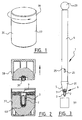
- The invention is now further illustrated by way of an exemplary embodiment, with reference being made to the annexed drawings, in which:
- Fig. 1 is a perspective view of a two part cylindrical radiation shielding enclosure in which a container with radioactive material is stored, indicating the direction in which it is opened,
- Fig. 2 is a cross-sectional view of the radiation shielding enclosure of fig. 1 after opening, showing the container and radioactive capsule immediately before withdrawal,
- Fig. 3 is a side elevation of the handling device of the invention being used to withdraw the container from the radiation shielding enclosure,
- Fig. 4 is an enlarged scale cross-sectional view of the tip part of the handling device of fig. 3, showing the means for connection to the container and the release mechanism,
- Fig. 5 is a top view in the direction of the arrow V in fig. 4, showing the deforming member of the release machanism,
- Fig. 6 is a perspective top view of the tip part connected to the container in which the body of the handling device has been left out for reasons of clarity,
- Fig. 7 is a cross-sectional view of the body of the handling device,
- Figs. 8 and 9 are schematic cross-sectional views showing the rotating parts of the release mechanism operation in their two extreme positions, defining the retracted and extended position of the deforming member, and
- Fig. 10 is a view corresponding with fig. 4 and showing the container being disconnected from the handling tool by deforming the snap connecting members.
- A
device 1 for handling acontainer 2 with a capsule ofradioactive material 3 comprises anelongated body 4 having a tip 5. In the illustrated embodiment thebody 4 comprises a hollow tube accommodating the various functional elements of thehandling device 1.Means 6 are arranged at or near the tip for releasably connecting thehandling device 1 to thecontainer 2. These connectingmeans 6 are adapted for establishing a snap connection with thecontainer 2 and include a plurality of resiliently flexiblesnap connecting members 7 each having aguide surface 8 for engaging a protrudingperipheral flange 9 of thecontainer 2. - The
handling device 1 further comprises arelease mechanism 10 acting on theconnecting means 6. Thisrelease mechanism 10 is adapted to deform thesnap connecting members 7 and hold them in their deformed states. To that end therelease mechanism 10 includes adeforming member 11 that is movably arranged in thebody 4 and operating means 12 that are operatively connected to the deformingmember 11. Thedeforming member 11 is slidable along an axis A of thebody 4 between a retracted position of rest (Fig. 4) in which it does not deform thesnap connecting members 7 and an extended release position (Fig. 10) in which it engages and deforms thesnap connecting members 7 so as to disconnect thehandling device 1 from thecontainer 2. - In order to prevent accidental release of the
container 2, the handling device further comprises means 13 for biasing the deformingmember 11 to its retracted position of rest. In the illustrated embodiment the deformingmember 11 has a stepped configuration defining ashoulder 14 and the biasing means 13 comprise a compression spring arranged around the narrowed part of the deformingmember 11 and held between theshoulder 14 and alocking ring 15, which also serves as bearing (Fig. 4). - The
operating means 12 are adapted to force the deformingmember 11 to its extended release position against the action of the biasing means 13. In order to avoid inadvertent operation of thehandling device 1, therelease mechanism 10 is adapted for double-handed operation. To this end the operating means 12 include twoparts body 4. Theseparts parts engaging surfaces parts coaxial bores pin 22 about which theparts - One of these parts,
part 16, is connected to (or in this case integrally formed with) thedeforming member 11, while theother part 17 is connected to a turningknob 23 protruding from thebody 4. In fact, thepart 17 carrying theknob 23 is rotatably arranged within thebody 4 and held therein by alocking ring 27 surrounding a narrowed end of the rotatingpart 17 and also serving as bearing for that part 17 (Fig. 7). On the other hand, thepart 16 carrying thedeforming member 11 is slidably arranged in thebody 4. In order to prevent thispart 16 from rotating within thebody 4 it has atransverse bore 24 into which ananti-rotation pin 25 is inserted. Thisanti-rotation pin 25 is slidably received inlongitudinal slots 26 formed inbody 4. - In the illustrated embodiment the deforming
member 11 comprises ashaft 28 carrying a propellor shaped deformingelement 29 having a plurality of engagement surfaces 30, each corresponding with one of thesnap connecting members 7. Thus, when moving the deformingmember 11 to its extended position through use of the operating means 12, the engagement surfaces will contact the insides of thesnap connecting members 7, bending these outward to disengage from the flange orridge 9 of the container 2 (Fig. 10). - In the illustrated embodiment of the handling device the tip 5 is formed by a disposable
hollow tip part 31 that is releasably connected to thebody 4. Thistip part 31 is tapered, having a relativelywide opening 32 which may be slid and clamped around the end of thebody 4 from which the deformingmember 11 protrudes and a relativelynarrow opening 33 defined by the free ends of thesnap connecting members 7. Thewider opening 32 is provided with inwardly protrudingresilient ridges 34 which ensure a tight fit but still allow thetip part 31 to be released from the body without requiring excessive force. Between thesnap connecting members 7 inwardly extendingsupports 35 are arranged, which limit the movement of thecontainer 2 when this is connected to thetip part 31. - Using the
handling device 1 described above, thecontainer 2 with the capsule ofradioactive material 3 that is stored in aradiation shielding enclosure 36 may be safely handled. First of all, theradiation shielding enclosure 36, which may consist of abody 37 and alid 38, is opened by unscrewing the lid 38 (Fig. 1). Since thelid 38 carries a plug-type lid 39 closing thecontainer 2, unscrewing thelid 38 will simultaneously lead to thecontainer 2 being opened (Fig. 2). Thecontainer 2 is arranged in thebody 37 of the radiation shielding enclosure with itsflange 9 protruding therefrom, so that this is easily accessible to thehandling device 1. Thehandling device 1 is then inserted into theradiation shielding enclosure 36 and connected to thecontainer 2 by means of thesnap connecting members 7 engaging theflange 9. Thesnap connecting members 7 are bent outward as the handling device is lowered onto thecontainer 2, due to theirguide surfaces 8 sliding along the sloping edge of thecontainer flange 9. - After the
handling device 1 has been connected to thecontainer 2, thecontainer 2 may be taken from theradiation shielding enclosure 36 by simply pulling it from thebody 37, thus releasing asnap connection 40 between thecontainer 2 and the enclosure body 37 (Fig. 3). Thecontainer 2 is then ready to be handled, for instance to be inserted into a well-type ionization chamber for measuring the radioactive content of thecapsule 3. - After insertion of the
container 2, the ionization chamber may be activated to measure the radioactivity of the material in thecontainer 2. Since the ionization chamber is well-shaped, theelongated handling device 1 has no discernible effect on the measurement. Thecontainer 2 may then be withdrawn from the ionization chamber and returned to itsradiation shielding container 36, where it may be pressed into thebody 37 again, thus re-establishing the snap connecting 40. After replacing thecontainer 2 in thebody 37, it may be released from thehandling device 1 by using the operating means 12. To this end the user holds thebody 4 of thehandling device 1 in one hand and theknob 23 in the other. By then turning theknob 23 relative to thebody 4, using both hands, theparts angled surfaces parts member 11 is extended, compressing the biasingspring 13 and bending thesnap connecting members 7 outward so as to disconnect thecontainer 2 from thehandling device 1. When the user releases his grip on the handling device, the biasingspring 13 will force the deformingmember 11 back to its retracted position, thus rotating theparts body 4 andknob 23 back to their initial position. - After the
handling device 1 has been disconnected from thecontainer 2, a patient may take thebody 37 holding theopen container 2 and put it to his lips to swallow thecapsule 3. - Alternatively, the
lid 38 may first be screwed back onto thebody 37, thus simultaneously closing theradiation shielding enclosure 36 and thecontainer 2. Theenclosure 36 may then be temporarily stored until the patient is ready to swallow theradioactive material 3, or it may be transported to a location where the patient is waiting for theradioactive material 3. - Although the handling method and device of the invention have been described above by way of a single exemplary embodiment, it will be clear that the invention may be practiced in various other ways. If for instance it would be preferable to shield the user's hands from radiation by using a bent or curved body, the operating means could include a transmission for transmitting the rotary movement from the knob to the tip. Moreover, the connecting means could be embodied in a different way, in which case the release mechanism would also have to be modified. It is also conceivable to use different ways of operating the release mechanism, for instance by a trigger or the like.
- Consequently, the scope of the invention is determined solely by the annexed claims.
Claims (22)
- Method of handling a container with radioactive material that is stored in a radiation shielding enclosure, comprising the steps of:a) inserting a substantially elongated handling device into the radiation shielding enclosure,b) connecting the handling device to the container,c) taking the container from the radiation shielding enclosure,d) performing one or more activities with or on the container,e) replacing the container into the radiation shielding enclosure, andf) disconnecting the handling device from the container.
- Method as claimed in claim 1, wherein the connecting step includes snapping the handling device onto the container.
- Method as claimed in claim 2, wherein the handling device includes at least one resiliently flexible snap connecting member having a guide surface and wherein the connecting step includes pressing the at least one snap connecting member with its guide surface onto the container such that the snap connecting member is temporarily deformed and then returns to its undeformed state, thus engaging a part of the container.
- Method as claimed in claim 3, wherein the container has a protruding peripheral flange or ridge and wherein the handling device includes a plurality of snap connecting members engaging said flange or ridge.
- Method as claimed in claim 3 or 4, wherein the disconnecting step includes deforming the at least one snap connecting member to disengage it from the container and then pulling back the handling device while holding the at least one snap connecting member in its deformed state.
- Method as claimed in claims 4 and 5, wherein the snap connecting members engage said flange or ridge from the outside and wherein the disconnecting step includes bending the snap connecting members outwards.
- Method as claimed in claim 5 or 6, wherein the handling device includes a release mechanism acting on the at least one snap connecting member and wherein the disconnecting step includes operating the release mechanism.
- Method as claimed in claim 7, wherein a user holds the handling device in one hand and wherein the release mechanism is operated by the user's other hand.
- Method as claimed in any one of the preceding claims, wherein the activities performing step includes measuring the radioactivity of the material in the container.
- Method as claimed in claim 9, wherein the activities performing step includes Lhe sub-steps of:d1) inserting the handling device holding the container into a well-type ionization chamber,d2) measuring the radioactivity of the material in the ionization chamber, andd3) retracting the handling device holding the container from the ionization chamber.
- Device for handling a container with radioactive material, comprising an elongated body having a tip and including means arranged at or near the tip for releasably connecting the device to the container.
- Handling device as claimed in claim 11, wherein the connecting means are adapted for establishing a snap connection with the container.
- Handling device as claimed in claim 12, wherein the connecting means include at least one resiliently flexible snap connecting member having a guide surface for engaging a part of the container.
- Handling device as claimed in claim 13, further comprising a plurality of snap connecting members for engaging a protruding peripheral flange or ridge of the container.
- Handling device as claimed in any one of claims 11 to 14, further comprising a release mechanism acting on the connecting means.
- Handling device as claimed in claim 13 or 14 and 15, wherein the release mechanism is adapted to deform the at least one snap connecting member and hold it in its deformed state.
- Handling device as claimed in claim 16, wherein the release mechanism includes at least one deforming member that is movably arranged in the body and operating means operatively connected to the at least one deforming member.
- Handling device as claimed in claim 17, further comprising means for biasing the at least one deforming member to a position of rest in which it does not deform the at least one snap connecting member, the operating means being adapted to move the at least one deforming member against the biasing means to a release position in which it does deform the at least one snap connecting member.
- Handling device as claimed in any one of claims 15 to 18, wherein the release mechanism is adapted for double-handed operation.
- Handling device as claimed in claims 17 or 18 and 19, wherein the operating means include two parts that are rotatable around a common axis and movable along the common axis, the rotating parts comprising mutually engaging surfaces running at an angle to the common axis, one of the parts being connected to the at least one deforming member.
- Handling device as claimed in any one of claims 17 to 20, wherein the deforming member comprises a shaft having a plurality of engagement surfaces, each of which corresponds with a snap connecting member.
- Handling device as claimed in any one of claims 11 to 21, wherein the tip is formed by a disposable tip part releasably connected to the body.
Priority Applications (5)
| Application Number | Priority Date | Filing Date | Title |
|---|---|---|---|
| EP05022433A EP1775733A1 (en) | 2005-10-14 | 2005-10-14 | Method and device for handling a container with radioactive material |
| US12/090,127 US20080265183A1 (en) | 2005-10-14 | 2006-10-16 | Method and Device for Handling a Container with Radioactive Material |
| JP2008535787A JP2009511920A (en) | 2005-10-14 | 2006-10-16 | Method and device for handling containers with radioactive material |
| EP06826110A EP1966804A1 (en) | 2005-10-14 | 2006-10-16 | Method and device for handling a container with radioactive material |
| PCT/US2006/040539 WO2007047666A1 (en) | 2005-10-14 | 2006-10-16 | Method and device for handling a container with radioactive material |
Applications Claiming Priority (1)
| Application Number | Priority Date | Filing Date | Title |
|---|---|---|---|
| EP05022433A EP1775733A1 (en) | 2005-10-14 | 2005-10-14 | Method and device for handling a container with radioactive material |
Publications (1)
| Publication Number | Publication Date |
|---|---|
| EP1775733A1 true EP1775733A1 (en) | 2007-04-18 |
Family
ID=35787489
Family Applications (2)
| Application Number | Title | Priority Date | Filing Date |
|---|---|---|---|
| EP05022433A Withdrawn EP1775733A1 (en) | 2005-10-14 | 2005-10-14 | Method and device for handling a container with radioactive material |
| EP06826110A Withdrawn EP1966804A1 (en) | 2005-10-14 | 2006-10-16 | Method and device for handling a container with radioactive material |
Family Applications After (1)
| Application Number | Title | Priority Date | Filing Date |
|---|---|---|---|
| EP06826110A Withdrawn EP1966804A1 (en) | 2005-10-14 | 2006-10-16 | Method and device for handling a container with radioactive material |
Country Status (4)
| Country | Link |
|---|---|
| US (1) | US20080265183A1 (en) |
| EP (2) | EP1775733A1 (en) |
| JP (1) | JP2009511920A (en) |
| WO (1) | WO2007047666A1 (en) |
Families Citing this family (5)
| Publication number | Priority date | Publication date | Assignee | Title |
|---|---|---|---|---|
| FR2998822B1 (en) * | 2012-12-04 | 2015-02-20 | Commissariat Energie Atomique | LOCKING / UNLOCKING SYSTEM, APPLICATION TO SAMPLE DOOR HANDLING OF NUCLEAR MATERIALS |
| US9757306B2 (en) * | 2013-03-13 | 2017-09-12 | Bayer Healthcare Llc | Vial container with collar cap |
| CN118742357B (en) | 2022-02-21 | 2026-02-03 | 拜耳医药保健有限责任公司 | Systems, methods, and devices for delivery of therapeutic or diagnostic agents |
| CN114927252A (en) * | 2022-05-23 | 2022-08-19 | 成都纽瑞特医疗科技股份有限公司 | Container device for administering a radiopharmaceutical and method of administering a radiopharmaceutical |
| TW202603747A (en) * | 2024-03-29 | 2026-01-16 | 美商亞特生物公司 | Radionuclide source clip attachment system |
Citations (5)
| Publication number | Priority date | Publication date | Assignee | Title |
|---|---|---|---|---|
| US3120613A (en) * | 1956-02-13 | 1964-02-04 | Technical Operations Inc | Radioactive source storage container with elongated flexible means for removing sources from the container |
| US5342158A (en) * | 1992-09-30 | 1994-08-30 | Gamma-Metrics | Handling and deploying radioactive sources |
| FR2742088A1 (en) * | 1995-12-11 | 1997-06-13 | Framatome Sa | Remote handling device for screwing and unscrewing of screws |
| WO2000052707A1 (en) * | 1999-03-02 | 2000-09-08 | Mallinckrodt Inc. | Holder for radioactive substances |
| EP1551035A1 (en) * | 2003-12-31 | 2005-07-06 | Services Petroliers Schlumberger | Handling tool for radioactive sources of logging while drilling devices |
Family Cites Families (1)
| Publication number | Priority date | Publication date | Assignee | Title |
|---|---|---|---|---|
| US4144461A (en) * | 1977-01-17 | 1979-03-13 | Victoreen, Inc. | Method and apparatus for assay and storage of radioactive solutions |
-
2005
- 2005-10-14 EP EP05022433A patent/EP1775733A1/en not_active Withdrawn
-
2006
- 2006-10-16 JP JP2008535787A patent/JP2009511920A/en active Pending
- 2006-10-16 EP EP06826110A patent/EP1966804A1/en not_active Withdrawn
- 2006-10-16 WO PCT/US2006/040539 patent/WO2007047666A1/en not_active Ceased
- 2006-10-16 US US12/090,127 patent/US20080265183A1/en not_active Abandoned
Patent Citations (5)
| Publication number | Priority date | Publication date | Assignee | Title |
|---|---|---|---|---|
| US3120613A (en) * | 1956-02-13 | 1964-02-04 | Technical Operations Inc | Radioactive source storage container with elongated flexible means for removing sources from the container |
| US5342158A (en) * | 1992-09-30 | 1994-08-30 | Gamma-Metrics | Handling and deploying radioactive sources |
| FR2742088A1 (en) * | 1995-12-11 | 1997-06-13 | Framatome Sa | Remote handling device for screwing and unscrewing of screws |
| WO2000052707A1 (en) * | 1999-03-02 | 2000-09-08 | Mallinckrodt Inc. | Holder for radioactive substances |
| EP1551035A1 (en) * | 2003-12-31 | 2005-07-06 | Services Petroliers Schlumberger | Handling tool for radioactive sources of logging while drilling devices |
Also Published As
| Publication number | Publication date |
|---|---|
| US20080265183A1 (en) | 2008-10-30 |
| EP1966804A1 (en) | 2008-09-10 |
| JP2009511920A (en) | 2009-03-19 |
| WO2007047666A1 (en) | 2007-04-26 |
Similar Documents
| Publication | Publication Date | Title |
|---|---|---|
| US11383038B2 (en) | Pre-filled cartridge-based drug delivery device | |
| EP1323444B1 (en) | Medical needle assemblies | |
| US10179211B2 (en) | Safety needle device | |
| US4994042A (en) | Combined catheter and needle | |
| US20220203042A1 (en) | Safety housing based implant/medicament injecting system | |
| US20130172820A1 (en) | IV Catheter Insertion Device and Method of Using It | |
| US7744558B2 (en) | Pill plunger | |
| US20030125677A1 (en) | Medical needle assemblies | |
| AU2019229849A1 (en) | Radiotherapy seeds and applicators | |
| US8211065B2 (en) | Enveloping needle stick protection device | |
| JP2009502344A (en) | Radiopharmaceutical dispensing device with counterforce access mechanism, system and method | |
| US20080265183A1 (en) | Method and Device for Handling a Container with Radioactive Material | |
| CN119013073A (en) | Device for subcutaneous insertion of solid media | |
| US11554216B2 (en) | Shielded syringe holding device for filling a syringe with a radioactive solution | |
| JP2009511920A5 (en) | ||
| CN219090819U (en) | Needle cap unlocking and returning device for radiopharmaceutical syringe | |
| CA3018120A1 (en) | Medical and dental safety syringe | |
| HK40035141B (en) | Radiotherapy seeds and applicators | |
| AU4238802A (en) | Medical needle assemblies |
Legal Events
| Date | Code | Title | Description |
|---|---|---|---|
| PUAI | Public reference made under article 153(3) epc to a published international application that has entered the european phase |
Free format text: ORIGINAL CODE: 0009012 |
|
| AK | Designated contracting states |
Kind code of ref document: A1 Designated state(s): AT BE BG CH CY CZ DE DK EE ES FI FR GB GR HU IE IS IT LI LT LU LV MC NL PL PT RO SE SI SK TR |
|
| AX | Request for extension of the european patent |
Extension state: AL BA HR MK YU |
|
| AKX | Designation fees paid | ||
| REG | Reference to a national code |
Ref country code: DE Ref legal event code: 8566 |
|
| STAA | Information on the status of an ep patent application or granted ep patent |
Free format text: STATUS: THE APPLICATION IS DEEMED TO BE WITHDRAWN |
|
| 18D | Application deemed to be withdrawn |
Effective date: 20071019 |