EP1775507A1 - Fitting für Rohrleitungen - Google Patents
Fitting für Rohrleitungen Download PDFInfo
- Publication number
- EP1775507A1 EP1775507A1 EP05022203A EP05022203A EP1775507A1 EP 1775507 A1 EP1775507 A1 EP 1775507A1 EP 05022203 A EP05022203 A EP 05022203A EP 05022203 A EP05022203 A EP 05022203A EP 1775507 A1 EP1775507 A1 EP 1775507A1
- Authority
- EP
- European Patent Office
- Prior art keywords
- connecting piece
- holding
- compression sleeve
- retaining rib
- fitting according
- Prior art date
- Legal status (The legal status is an assumption and is not a legal conclusion. Google has not performed a legal analysis and makes no representation as to the accuracy of the status listed.)
- Granted
Links
- 230000006835 compression Effects 0.000 claims description 49
- 238000007906 compression Methods 0.000 claims description 49
- 238000007789 sealing Methods 0.000 claims description 44
- 239000002184 metal Substances 0.000 description 7
- 239000012530 fluid Substances 0.000 description 4
- 239000000463 material Substances 0.000 description 3
- 150000001875 compounds Chemical class 0.000 description 2
- 238000009434 installation Methods 0.000 description 2
- 230000000295 complement effect Effects 0.000 description 1
- 238000010276 construction Methods 0.000 description 1
- 230000000694 effects Effects 0.000 description 1
- 238000005096 rolling process Methods 0.000 description 1
- 229910001220 stainless steel Inorganic materials 0.000 description 1
- 239000010935 stainless steel Substances 0.000 description 1
- 230000007704 transition Effects 0.000 description 1
- 238000003466 welding Methods 0.000 description 1
Images


Classifications
-
- F—MECHANICAL ENGINEERING; LIGHTING; HEATING; WEAPONS; BLASTING
- F16—ENGINEERING ELEMENTS AND UNITS; GENERAL MEASURES FOR PRODUCING AND MAINTAINING EFFECTIVE FUNCTIONING OF MACHINES OR INSTALLATIONS; THERMAL INSULATION IN GENERAL
- F16L—PIPES; JOINTS OR FITTINGS FOR PIPES; SUPPORTS FOR PIPES, CABLES OR PROTECTIVE TUBING; MEANS FOR THERMAL INSULATION IN GENERAL
- F16L13/00—Non-disconnectible pipe-joints, e.g. soldered, adhesive or caulked joints
- F16L13/14—Non-disconnectible pipe-joints, e.g. soldered, adhesive or caulked joints made by plastically deforming the material of the pipe, e.g. by flanging, rolling
- F16L13/141—Non-disconnectible pipe-joints, e.g. soldered, adhesive or caulked joints made by plastically deforming the material of the pipe, e.g. by flanging, rolling by crimping or rolling from the outside
- F16L13/143—Non-disconnectible pipe-joints, e.g. soldered, adhesive or caulked joints made by plastically deforming the material of the pipe, e.g. by flanging, rolling by crimping or rolling from the outside with a sealing element placed around the male part before crimping or rolling
-
- F—MECHANICAL ENGINEERING; LIGHTING; HEATING; WEAPONS; BLASTING
- F16—ENGINEERING ELEMENTS AND UNITS; GENERAL MEASURES FOR PRODUCING AND MAINTAINING EFFECTIVE FUNCTIONING OF MACHINES OR INSTALLATIONS; THERMAL INSULATION IN GENERAL
- F16L—PIPES; JOINTS OR FITTINGS FOR PIPES; SUPPORTS FOR PIPES, CABLES OR PROTECTIVE TUBING; MEANS FOR THERMAL INSULATION IN GENERAL
- F16L13/00—Non-disconnectible pipe-joints, e.g. soldered, adhesive or caulked joints
- F16L13/14—Non-disconnectible pipe-joints, e.g. soldered, adhesive or caulked joints made by plastically deforming the material of the pipe, e.g. by flanging, rolling
- F16L13/148—Non-disconnectible pipe-joints, e.g. soldered, adhesive or caulked joints made by plastically deforming the material of the pipe, e.g. by flanging, rolling specially designed to ensure an intended leakage until correct deformation
-
- F—MECHANICAL ENGINEERING; LIGHTING; HEATING; WEAPONS; BLASTING
- F16—ENGINEERING ELEMENTS AND UNITS; GENERAL MEASURES FOR PRODUCING AND MAINTAINING EFFECTIVE FUNCTIONING OF MACHINES OR INSTALLATIONS; THERMAL INSULATION IN GENERAL
- F16L—PIPES; JOINTS OR FITTINGS FOR PIPES; SUPPORTS FOR PIPES, CABLES OR PROTECTIVE TUBING; MEANS FOR THERMAL INSULATION IN GENERAL
- F16L33/00—Arrangements for connecting hoses to rigid members; Rigid hose connectors, i.e. single members engaging both hoses
- F16L33/20—Undivided rings, sleeves or like members contracted on the hose or expanded in the hose by means of tools; Arrangements using such members
- F16L33/207—Undivided rings, sleeves or like members contracted on the hose or expanded in the hose by means of tools; Arrangements using such members only a sleeve being contracted on the hose
- F16L33/2071—Undivided rings, sleeves or like members contracted on the hose or expanded in the hose by means of tools; Arrangements using such members only a sleeve being contracted on the hose the sleeve being a separate connecting member
- F16L33/2078—Undivided rings, sleeves or like members contracted on the hose or expanded in the hose by means of tools; Arrangements using such members only a sleeve being contracted on the hose the sleeve being a separate connecting member connected to the rigid member via an intermediate element
Definitions
- the invention relates to a fitting for pipelines with at least one connecting piece, to which the end of a pipeline can be connected.
- the invention particularly relates to a fitting or press fitting with more than one connection piece.
- This may be a linear fitting with two opposing connecting pieces arranged at its ends or, for example, an angle-shaped fitting with two connecting pieces arranged at the angle ends.
- the fitting according to the invention can also be designed as a T-shaped fitting with three connecting pieces.
- the end of a pipe to be connected is either pushed onto the connection piece or inserted into the connection piece.
- At least one sealing element which is formed, for example, as an O-ring, runs over the outer circumference of the connection piece.
- at least one over the outer circumference of the connecting piece circumferential raised area is provided, on which the pipe end is pushed as it were form-fitting and which serves to hold the pipe end to the spigot.
- the inner surface of the pushed pipe end also comes in contact with the top of the sealing element.
- connection between a pipe end and a connecting piece is made as follows. If the end of the pipe is to be pushed onto the connection piece, a compression sleeve is positioned above the connection piece, which surrounds the connection piece at a radial distance. The end of the pipeline is then pushed onto the connecting piece between the compression sleeve and the connecting piece. To fix this connection is then the compression sleeve with a pressing tool pressed, so that the pipe end plastically deformed. The pipe end is then pressed onto a sealing element or on a sealing ring, so to speak, so that a tight connection results. When installing on construction sites usually a variety of such compounds must be made.
- the invention is based on the technical problem of specifying a fitting of the type mentioned in the not properly prepared or not or not properly pressed joints are easily recognizable and nonetheless can be produced in a simple and inexpensive manner.
- the invention teaches a fitting or press fitting for pipelines with at least one connecting piece, to which the end of a pipeline can be connected, wherein at least two holding ribs, which encircle the circumference of the connecting piece, are provided on the connecting piece for holding an open or pushed-in pipe end, wherein in each retaining rib at least one axial flow channel is introduced and wherein the flow channel is arranged in the one retaining rib in the circumferential direction offset from the flow channel in the other retaining rib.
- the fitting is made of metal, preferably of gunmetal. According to another embodiment, the fitting is made of plastic.
- That a holding rib is provided for holding an up or inserted pipe end means, in particular, that the up or inserted pipe end is in positive and / or frictional contact with the holding rib over the circumference of the pipe end, so that the pipe end does not readily slides or slips off the connecting piece.
- An inventive flow channel passes through a retaining rib in the axial direction. Staggered arrangement of the flow channels means that the staggered flow channels are not aligned in the axial direction.
- the invention is based on the finding that the above-described technical problem can be solved very effectively with the feature combination according to the invention.
- the flow channels passing through the retaining ribs initially ensure that, even with a sealing connection between the pushed-on pipe end and holding ribs in the unpressed state, a leak can nonetheless be detected at any time in the above-described pressure test.
- This the axial flow channels flowing fluid medium causes these leaks.
- the fluid medium is guided past the flow channels as it were at a primary sealing connection between the pushed-on pipe end and holding ribs.
- the fact that the axial flow channels of the adjacent retaining ribs are arranged offset from one another has a special significance in the context of the invention.
- the at least two holding ribs extend over the outer circumference of the connecting piece and accordingly the end of the pipe is pushed onto the connecting piece or on the holding ribs of the connecting piece.
- the connecting piece of a is expediently surrounded on the fitting fixed compression sleeve, so that the pipe end between the connecting piece and compression sleeve can be inserted or pushed onto the connecting piece.
- the pipe end, connecting piece and compression sleeve are cylindrical. If the pipe end between the compression sleeve and connection piece is pushed onto the connection piece, the compression sleeve can then be pressed.
- the at least two holding ribs can also extend over the inner circumference of the connecting piece.
- the pipe end is inserted into the connection piece.
- the connecting piece of the fitting is then pressed, so that the connecting piece is plastically deformed and in this way, the above-mentioned sealing element comes into sealing contact with the pipe end and at least the largest part of the flow channels is closed by the material of the plastically deformed connecting piece.
- At least one circumferential over the circumference of the connecting piece receiving groove is provided with therein sealing element and that at least a portion or at least a portion of the sealing element with respect to the most protruding from the connecting piece wall top or upper edge of a retaining rib in Radial direction is set back.
- the at least one extends Receiving groove with the sealing element received therein over the outer circumference of the connecting piece.
- the sealing element is preferably a sealing ring or O-ring. According to another embodiment, the sealing element may also be sealing compound injected into the receiving groove.
- the sealing element is arranged over the entire circumference of the connecting piece relative to the retaining rib or against the retaining ribs reset, ie, the top of the sealing element lies over the entire circumference of the connecting piece under the top or top edge of the retaining ribs.
- a sealing element or at least a part of this sealing element is arranged opposite at least two retaining ribs in the manner described reset.
- the recessed arrangement of the sealing element or the sealing elements is of particular importance in the context of the invention. First, this can be avoided that a sealing element in the unpressed state assumes an unwanted sealing function and thus could simulate a compressed state in a pressure test.
- the sealing element is damaged when pushed or when inserting the pipe end.
- the arrangement requires that a relatively simple frictional resistance-free sliding of the pipe end is possible. This is especially true when the holding function fulfilling holding ribs according to a preferred embodiment of the invention have a V-shaped cross section or a U-shaped cross section, wherein the V-tip or the U-curvature with the pipe end or with the inner surface of the pipe end in Contact is coming.
- a receiving groove with the sealing element received therein is arranged between two holding ribs, in each of which flow channels offset from one another are provided. That's it Sealing element expediently arranged opposite to two retaining ribs in the manner described reset.
- a connection piece has two receiving grooves each having a sealing element received therein, and each of these receiving grooves or each of these sealing elements is arranged between two holding ribs.
- a preferred embodiment of the invention is characterized in that at least three each around the circumference of the connecting piece circumferential retaining ribs are provided and that the at least one axial flow channel of the first retaining rib both with respect to the at least one axial flow channel of the second retaining rib and with respect to the at least one axial flow channel the third retaining rib is offset in the circumferential direction.
- the at least one axial flow channel of the second retaining rib is offset in the circumferential direction in relation to the at least one axial flow channel of the third retaining rib.
- all the axial flow channels of the first retaining rib are arranged offset relative to all axial flow channels of the second retaining rib as well as with respect to all axial flow channels of the third retaining rib and all axial flow channels of the second retaining rib are arranged offset from all axial flow channels of the third retaining rib.
- a holding rib has at least two flow channels.
- at least three axial flow channels are provided in a retaining rib. If three or more axial flow channels are introduced in a retaining rib, these axial flow channels preferably have equal distances or approximately equal distances from each other in the circumferential direction.
- the flow channels of the holding ribs are formed open on the pipe side.
- the flow channels are thus open to the outside axial grooves.
- the flow channels are formed in cross-section U-shaped or V-shaped.
- the fitting or its connection piece consists of metal, preferably of gunmetal.
- the connecting pieces of a metal fitting according to the invention preferably have a circumferentially extending knurled holding area for holding the pipe end.
- This knurled holding area is expediently in the push-on direction of the pipe end behind the holding ribs or behind at least part of the holding ribs.
- the knurled holding area preferably consists of axial ribs with a holding function for the pipe end, wherein the upper edges of these axial ribs are preferably arranged at the same level as the upper edges of the holding ribs.
- the knurled holding area has axial grooves between the axial ribs.
- this knurling is combined, d. H. introduced in one step with the axial flow channels in the holding ribs.
- a suitable rolling tool is expediently used.
- the knurling is performed increased in a particularly preferred embodiment relative to the front retaining ribs in order to hold even chamfered pipe ends in each case.
- a raised holding region made of plastic is preferably provided, which extends over the circumference of the connecting piece.
- This holding area made of plastic is expediently in Postponement of the pipe end behind the holding ribs or behind at least a portion of the holding ribs.
- This holding area made of plastic like the knurled holding area of the metal fitting described above, also fulfills a holding function for the pushed-on pipe end.
- the upper side of the raised holding area made of plastic is preferably at the same level or approximately at the same level as the upper edge of the holding ribs.
- the holding area made of plastic is executed increased in a particularly preferred embodiment relative to the front retaining ribs in order to keep chamfered pipe ends in each case.
- a very preferred embodiment of the invention is characterized in that a compression sleeve is provided for connection to an associated connection piece, which compression sleeve is connected at its connection end with a connection ring, with which it can be connected to the connection piece and that the compression sleeve in her to the connecting piece connected unpressed state is rotatable relative to the connecting ring.
- the compression sleeve is preferably made of metal, preferably of stainless steel. It is within the scope of the invention that the compression sleeve is a deep-drawn part. It is also within the scope of the invention that the compression sleeve is cylindrical or approximately cylindrical in shape.
- the connecting ring is preferably made of plastic.
- the connecting ring forms as it were a transition element between the compression sleeve and connecting piece. It is within the scope of the invention that according to the preferred embodiment described above, the compression sleeve is permanently connected to the connection ring, but (in the unpressed state) is rotatable relative to the connection ring. Preferably, a corresponding positive connection between the compression sleeve and connecting ring is realized, on the one hand ensures the insolubility and on the other hand makes the relative rotation of the compression sleeve to the connection ring possible. It has proven itself, this the Fix plastic connection ring by ultrasonic welding to the compression sleeve.
- a projecting flange projecting beyond the circumference of the compression sleeve is provided on the end face of the compression sleeve facing away from the connection ring. It is within the scope of the invention that the connecting ring in the radial direction also protrudes beyond the press sleeve jacket, so that the connecting ring at the other end of the compression sleeve also forms a flange.
- the two aforementioned flanges have proven to be so far, as they allow optimal guidance and positioning of the pressing tool.
- the connecting ring is connected via a latching connection to the connecting piece, which latching connection is made detachable in the non-pressed state of the compression sleeve.
- a plurality of locking lugs are distributed over the circumference of the connecting ring and these locking lugs preferably engage in a locking groove of the connecting piece.
- the connection ring is rotatable relative to the connection piece.
- the compression sleeve has at least one opening serving as a viewing window at its connection-side end.
- the opening area of such a viewing window is expediently small in comparison to the press sleeve lateral surface.
- a plurality of openings distributed over the circumference of the compression sleeve or viewing window are provided. The fact that the viewing windows are provided in front of the connection ring in the compression sleeve jacket, can be detected through the viewing window, whether the pipe end is fully inserted on the associated connection piece or completely in the associated compression sleeve. Due to the relative rotatability this can be determined from each side of the fitting.
- connection ring has the particular advantage that the control described above by rotation of the press sleeve is also possible if the connection ring is hampered in its rotatability, for example by contact with an adjacent wall, so that the unit of connection ring and compression sleeve not common can be rotated relative to the connection piece.
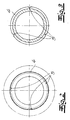
- the figures show fittings with two connecting pieces 1, wherein to a connecting piece 1, a pipe end 2 of a pipeline can be connected.
- the pipe end 2 is pushed onto an associated connection piece 1 and this pipe end 2 is then located between a compression sleeve 3 (Fig. 6) and the connecting piece 1.
- the compression sleeve 3 was not shown for the sake of simplicity.
- the compression sleeve 3 is pressed with a pressing tool, not shown, and thereby the pipe end 2 is plastically deformed, so that a sealing contact with the connecting piece 1 results.
- These retaining ribs 4 are provided for holding a deferred pipe end 2 (before pressing). The inner surface of the pipe end 2 comes into contact with the upper edges of the holding ribs 4, so that the pipe end 2 is held as it were positive and frictional before pressing on the connecting piece 1.
- FIGS. 1 to 5 A first embodiment of a fitting according to the invention is shown in FIGS. 1 to 5, in which the fitting consists of metal or gunmetal.
- the fitting is designed here as a linear fitting with two opposing connection pieces 1.
- three retaining ribs 4 are provided in each case, which rotate over the outer periphery of the associated connecting piece 1.
- three V-shaped axial flow channels 5 are provided in cross-section, which have the same distances from each other with respect to the circumference of a retaining rib 4 in the embodiment (see Fig. 2 to 4).
- the axial flow channels 5 of the first retaining rib 4 (FIG. 2) are offset with respect to both the axial flow channels 5 of the second retaining rib 4 (FIG.
- the axial flow channels 5 of the second retaining rib 4 (FIG. 3) are also offset relative to the axial flow channels 5 of the third retaining rib 4 (FIG. 4). According to the invention it is avoided that the axial flow channels 5 of two or more retaining ribs 4 complement each other in alignment with a linear axial channel.
- FIG. 1 two circumferential over the circumference of a connecting piece 1 receiving grooves 6 are each shown with each received therein sealing element 7.
- the sealing elements 7 are formed as O-rings.
- Each receiving groove 6 with sealing element 7 is arranged between two holding ribs 4.
- the sealing elements 7 are arranged opposite the upper edges of the retaining ribs 4 in the radial direction reset.
- the retaining ribs 4 protrude beyond the sealing elements 7, preferably in the exemplary embodiment over the entire circumference of the connecting piece 1.
- the metal fitting according to FIGS. 1 to 5 has a knurled holding region 8 on each connecting piece 1, which also serves to hold the respective associated pipe end 2 in the unpressed state.
- the knurled holding region 8 of a connecting piece 1 is in the direction of the end of the pipe 2 behind the retaining ribs 4.
- the knurled holding portion 8 has axial ribs 9 with V-shaped cross-section and axial grooves 10 also with V-shaped cross section (see in particular Fig. 5) , Preferably, this knurling is introduced together with the axial flow channels 5 in one step in the connecting piece 1.
- the upper edges of the axial ribs 9 are otherwise arranged at the same level or at the same height as the upper edges of the holding ribs 4.
- Fig. 6 shows a second embodiment of a fitting according to the invention, in which the fitting consists of plastic.
- This fitting is formed angularly with two mutually perpendicular connection piece 1.
- the press sleeves 3 are shown, which are arranged above the respective connecting piece 1 or above the pipe end 2. It is Also recognizable that the compression sleeves 3, the pipe ends 2 and the connecting piece 1 are cylindrical.
- Each connecting piece 1 of the plastic fitting according to FIG. 6 has a total of five retaining ribs 4.
- a plurality of axial flow channels 5 are introduced.
- the axial flow channels 5 of each retaining rib are offset relative to the axial flow channels 5 of the remaining retaining ribs 4.
- two receiving grooves 6 are provided with recorded sealing element 7 here.
- the sealing elements 7 are arranged here in the manner described above with respect to the upper edges of the retaining ribs 4 in the radial direction.
- Each compression sleeve 3 is connected in Fig. 6 to the respectively associated connection piece 1, in each case via a connection ring 11.
- the connection ring 11 is connected via a latching connection with the associated connection piece 1 and relative to the connection piece 1 is relatively rotatable.
- the compression sleeve 3 is connected to the associated connection ring 11 with the proviso that it (in the unpressed state) is rotatable relative to the connection ring 11. This was indicated in Fig. 6, as well as the relative rotatability of the connection ring 11.
- the compression sleeve 3 is inextricably connected via a corresponding positive connection with the connection ring 11, but relative to the connection ring 11 rotatable.
- the compression sleeve 3 has at its connection-side end serving as a viewing window openings 12.
- a viewing window openings 12 Preferably and in the exemplary embodiment may be distributed over the circumference of the compression sleeve 3 a total of three openings 12 with the same distance from each other.
- FIG. 6 it can be seen that the opening area of an opening 12 is small relative to the lateral surface of the compression sleeve 3. Through the viewing window can be seen whether the pipe end 2 properly and was fully inserted. Due to the relative rotatability, this is possible at virtually any point or on each side of the fitting.
- the pressing sleeves 3 each have at its front end a circumferential flange 13 projecting over its circumference.
- the connecting ring 11 each forms an opposite corresponding flange.
- the two flanges allow optimal guidance or positioning of a pressing tool.
- the plastic fitting in FIG. 6 has a raised holding area 14 for holding the pipe end 2 in the unpressed state.
- This raised holding portion 14 is arranged in the embodiment of FIG. 6 in the direction of the pipe end 2 behind the retaining ribs 4.
- the top of this raised holding portion 14 is expediently and arranged in the embodiment at the same level or at the same height as the upper edges of the retaining ribs 4.
- a receiving groove 6 with a received sealing element 7 between a holding rib 4 and this raised Holding area 14 is arranged.
Abstract
Description
- Die Erfindung betrifft einen Fitting für Rohrleitungen mit zumindest einem Anschlussstutzen, an dem das Ende einer Rohrleitung anschließbar ist. Die Erfindung betrifft insbesondere einen Fitting bzw. Pressfitting mit mehr als einem Anschlussstutzen. Dabei kann es sich um einen linearen Fitting mit zwei an seinen Enden angeordneten gegenüberliegenden Anschlussstutzen handeln oder aber beispielsweise um einen winkelförmigen Fitting mit zwei an den Winkelenden angeordneten Anschlussstutzen. Der erfindungsgemäße Fitting kann aber auch als T-förmiger Fitting mit drei Anschlussstutzen ausgebildet sein. Bei den vorstehend genannten Fittings wird das Ende einer anzuschließenden Rohrleitung entweder auf den Anschlussstutzen aufgeschoben oder in den Anschlussstutzen eingeschoben. Wenn zur Herstellung der Verbindung das Ende der Rohrleitung auf den Anschlussstutzen aufgeschoben werden muss, läuft über den Außenumfang des Anschlussstutzens zumindest ein Dichtelement um, das beispielsweise als O-Ring ausgebildet ist. Außerdem ist normalerweise zumindest ein über den Außenumfang des Anschlussstutzens umlaufender erhabener Bereich vorgesehen, auf den das Rohrleitungsende gleichsam formschlüssig aufgeschoben wird und der zum Halten des Rohrleitungsendes an dem Anschlussstutzen dient. Bei vielen Fittings kommt die Innenoberfläche des aufgeschobenen Rohrleitungsendes auch in Kontakt mit der Oberseite des Dichtelementes.
- Die Verbindung zwischen einem Rohrleitungsende und einem Anschlussstutzen wird wie folgt hergestellt. Wenn das Ende der Rohrleitung auf den Anschlussstutzen aufgeschoben werden soll, wird vorher eine Presshülse über dem Anschlussstutzen positioniert, die den Anschlussstutzen mit radialem Abstand umgibt. Das Ende der Rohrleitung wird dann zwischen Presshülse und Anschlussstutzen auf den Anschlussstutzen aufgeschoben. Zur Fixierung dieser Verbindung wird anschließend die Presshülse mit einem Presswerkzeug verpresst, so dass sich das Rohrleitungsende plastisch verformt. Das Rohrleitungsende wird dann auf ein Dichtelement bzw. auf einen Dichtring gleichsam aufgepresst, so dass eine dichte Verbindung resultiert. Bei Installationsarbeiten auf Baustellen muss in der Regel eine Vielzahl solcher Verbindungen hergestellt werden. Um festzustellen, ob alle Verbindungen ordnungsgemäß hergestellt bzw. verpresst wurden, wird normalerweise zur Probe ein Medium unter Druck bei der Abnahme der Installation durch das Rohrsystem geleitet. Man geht dabei davon aus, dass sich nicht ordnungsgemäß hergestellte Verbindungen durch Leckagen bemerkbar machen. Es kann aber vorkommen, dass beim Aufschieben des Rohrleitungsendes auf den Anschlussstutzen der über den Umfang des Anschlussstutzens umlaufende erhabene Bereich bereits in mehr oder weniger dichtenden Kontakt mit der Innenseite des Rohrleitungsendes kommt. Wenn an einer solchen Verbindungsstelle das Verpressen der Verbindung vergessen wird, ist es möglich, dass bei der beschriebenen Druckprobe eine Leckage an dieser Verbindungsstelle nicht festgestellt wird. Das kann dazu führen, dass die Rohrinstallation mit einer nicht verpressten Verbindungsstelle in Betrieb genommen wird. Zu einem späteren Zeitpunkt kommt es dann aber während des Betriebes des Rohrleitungssystems aufgrund von Druckstößen der durch das Rohrleitungssystem geführten fluiden Medien zu unerwünschten Leckagen.
- Der Erfindung liegt das technische Problem zugrunde, einen Fitting der eingangs genannten Art anzugeben, bei dem nicht ordnungsgemäß hergestellte bzw. nicht oder nicht ordnungsgemäß verpresste Verbindungsstellen problemlos erkennbar sind und der nichtsdestoweniger auf einfache und wenig aufwendige Weise herstellbar ist.
- Zur Lösung dieses technischen Problems lehrt die Erfindung einen Fitting bzw. Pressfitting für Rohrleitungen mit zumindest einem Anschlussstutzen, an den das Ende einer Rohrleitung anschließbar ist,
wobei an dem Anschlussstutzen zumindest zwei jeweils über den Umfang des Anschlussstutzens umlaufende Halterippen zum Halten eines auf- bzw. eingeschobenen Rohrleitungsendes vorgesehen sind,
wobei in jeder Halterippe zumindest ein axialer Strömungskanal eingebracht ist und wobei der Strömungskanal in der einen Halterippe in Umfangsrichtung versetzt zu dem Strömungskanal in der anderen Halterippe angeordnet ist. - Gemäß einer Ausführungsform der Erfindung besteht der Fitting aus Metall, vorzugsweise aus Rotguss. Nach einer anderen Ausführungsform besteht der Fitting aus Kunststoff.
- Dass eine Halterippe zum Halten eines auf- bzw. eingeschobenen Rohrleitungsendes vorgesehen ist, meint insbesondere, dass das auf- bzw. eingeschobene Rohrleitungsende über den Umfang des Rohrleitungsendes in formschlüssigem und/oder reibschlüssigem Kontakt mit der Halterippe steht, so dass das Rohrleitungsende nicht ohne weiteres von dem Anschlussstutzen gleitet bzw. rutscht. Ein erfindungsgemäßer Strömungskanal durchsetzt eine Halterippe in axialer Richtung. Versetzte Anordnung der Strömungskanäle meint, dass die versetzt angeordneten Strömungskanäle in axialer Richtung nicht fluchten.
- Der Erfindung liegt die Erkenntnis zugrunde, dass das oben dargelegte technische Problem mit der erfindungsgemäßen Merkmalskombination sehr effektiv gelöst werden kann. Die die Halterippen durchsetzenden Strömungskanäle gewährleisten zunächst, dass auch bei einer dichtenden Verbindung zwischen aufgeschobenem Rohrleitungsende und Halterippen im unverpressten Zustand nichtsdestoweniger jederzeit eine Leckage bei der oben erläuterten Druckprobe feststellbar ist. Das die axialen Strömungskanäle durchströmende fluide Medium verursacht diese Leckagen. Das fluide Medium wird über die Strömungskanäle gleichsam an einer primären dichtenden Verbindung zwischen aufgeschobenem Rohrleitungsende und Halterippen vorbeigeleitet. Dass die axialen Strömungskanäle der benachbarten Halterippen versetzt zueinander angeordnet sind, hat im Rahmen der Erfindung eine besondere Bedeutung. Beim Einsatz des Presswerkzeuges und beim Verpressen der Presshülse kann es vorkommen, dass beispielsweise aufgrund der Position der Pressbacken insbesondere aufgrund geringerer Presshülsen-Kompression bzw. plastischer Presshülsen-Verformung an den gegenüberliegenden Schließpunkten der beiden Pressbackenschalen ein Strömungskanal nicht durch das plastisch verformte Rohrleitungsende bzw. durch das Material des plastisch verformten Rohrleitungsendes geschlossen wird. Durch diesen im verpressten Zustand nicht verschlossenen Strömungskanal kann also fluides Medium strömen, wodurch eine Leckage verursacht werden könnte. Der Erfindung liegt die Erkenntnis zugrunde, dass ein weiterer Strömungskanal, der versetzt zu dem ersten Strömungskanal in einer benachbarten Halterippe vorgesehen ist, bei der plastischen Verformung des Rohrleitungsendes durch das Material des Rohrleitungsendes mit höchster Wahrscheinlichkeit verschlossen wird. Somit kann eine Leckage aufgrund der dichtenden Wirkung dieser letztgenannten Halterippe vermieden werden. Zu betonen ist, dass das technische Problem mit der erfindungsgemäßen Merkmalskombination einerseits auf sehr einfache und wenig aufwendige Weise und andererseits nichtsdestoweniger auf sehr effektive Weise gelöst wird.
- Nach besonders bevorzugter Ausführungsform der Erfindung verlaufen die zumindest zwei Halterippen über den Außenumfang des Anschlussstutzens und dementsprechend wird das Ende der Rohrleitung auf den Anschlussstutzen bzw. auf die Halterippen des Anschlussstutzens aufgeschoben. Dabei liegt es im Rahmen der Erfindung, dass der Anschlussstutzen von einer, zweckmäßigerweise am Fitting fixierten Presshülse umgeben wird, so dass das Rohrleitungsende zwischen Anschlussstutzen und Presshülse einschiebbar bzw. auf den Anschlussstutzen aufschiebbar ist. Es liegt weiterhin im Rahmen der Erfindung, dass Rohrleitungsende, Anschlussstutzen und Presshülse zylinderförmig ausgebildet sind. Wenn das Rohrleitungsende zwischen Presshülse und Anschlussstutzen auf den Anschlussstutzen aufgeschoben ist, kann anschließend das Verpressen der Presshülse erfolgen. Dabei wird das Rohrleitungsende ebenso wie die Presshülse plastisch verformt und auf diese Weise kommt ein weiter unten noch beschriebenes Dichtelement in dichtenden Kontakt mit dem Rohrleitungsende. Außerdem wird zumindest der größte Teil der Strömungskanäle in den Halterippen bei dieser plastischen Verformung verschlossen.
- Gemäß einer anderen Ausführungsform der Erfindung können die zumindest zwei Halterippen auch über den Innenumfang des Anschlussstutzens verlaufen. Bei dieser Ausführungsform wird das Rohrleitungsende in den Anschlussstutzen eingeschoben. Anschließend wird dann der Anschlussstutzen des Fittings verpresst, so dass der Anschlussstutzen plastisch verformt wird und auf diese Weise kommt das oben genannte Dichtelement in dichtenden Kontakt mit dem Rohrleitungsende und zumindest der größte Teil der Strömungskanäle wird von dem Material des plastisch verformten Anschlussstutzens verschlossen.
- Es liegt im Rahmen der Erfindung, dass zumindest eine über den Umfang des Anschlussstutzens umlaufende Aufnahmenut mit darin aufgenommenem Dichtelement vorgesehen ist und dass zumindest ein Teil bzw. zumindest ein Teilbereich des Dichtelementes gegenüber der am weitesten aus der Anschlussstutzenwand herausragenden Oberseite bzw. Oberkante einer Halterippe in radialer Richtung zurückgesetzt angeordnet ist. Nach sehr bevorzugter Ausführungsform der Erfindung verläuft dabei die zumindest eine Aufnahmenut mit dem darin aufgenommenen Dichtelement über den Außenumfang des Anschlussstutzens. Bei dem Dichtelement handelt es sich vorzugsweise um einen Dichtring bzw. O-Ring. Gemäß einer anderen Ausführungsform kann es sich bei dem Dichtelement aber auch um in die Aufnahmenut eingespritzte Dichtmasse handeln. Nach besonders bevorzugter Ausführungsform der Erfindung ist das Dichtelement über den gesamten Umfang des Anschlussstutzens gegenüber der Halterippe bzw. gegenüber den Halterippen zurückgesetzt angeordnet, d. h., die Oberseite des Dichtelementes liegt über den gesamten Umfang des Anschlussstutzens unter der Oberseite bzw. Oberkante der Halterippen. Gemäß sehr bevorzugter Ausführungsform der Erfindung ist ein Dichtelement bzw. zumindest ein Teil dieses Dichtelementes gegenüber zumindest zwei Halterippen in der beschriebenen Weise zurückgesetzt angeordnet. Der zurückgesetzten Anordnung des Dichtelementes oder der Dichtelemente kommt im Rahmen der Erfindung besondere Bedeutung zu. Zunächst kann dadurch vermieden werden, dass ein Dichtelement im unverpressten Zustand eine ungewollte abdichtende Funktion übernimmt und somit bei einer Druckprobe einen verpressten Zustand vortäuschen könnte. Außerdem wird durch die zurückgesetzte Anordnung vermieden, dass das Dichtelement beim Aufschieben bzw. beim Einschieben des Rohrleitungsendes beschädigt wird. Fernerhin bedingt die Anordnung, dass ein relativ einfaches reibwiderstandsfreies Aufschieben des Rohrleitungsendes möglich ist. Das gilt insbesondere, wenn die die Haltefunktion erfüllenden Halterippen nach bevorzugter Ausführungsform der Erfindung einen V-förmigen Querschnitt oder einen U-förmigen Querschnitt aufweisen, wobei die V-Spitze bzw. die U-Wölbung mit dem Rohrleitungsende bzw. mit der Innenoberfläche des Rohrleitungsendes in Kontakt kommt.
- Es liegt im Rahmen der Erfindung, dass eine Aufnahmenut mit darin aufgenommenem Dichtelement zwischen zwei Halterippen angeordnet ist, in denen jeweils zueinander versetzte Strömungskanäle vorgesehen sind. Dabei ist das Dichtelement zweckmäßigerweise gegenüber beiden Halterippen in der beschriebenen Weise zurückgesetzt angeordnet. Gemäß einer Ausführungsform der Erfindung weist ein Anschlussstutzen zwei Aufnahmenuten mit jeweils darin aufgenommenem Dichtelement auf und jede dieser Aufnahmenuten bzw. jedes dieser Dichtelemente ist zwischen zwei Halterippen angeordnet.
- Eine bevorzugte Ausführungsform der Erfindung ist dadurch gekennzeichnet, dass zumindest drei jeweils über den Umfang des Anschlussstutzens umlaufende Halterippen vorgesehen sind und dass der zumindest eine axiale Strömungskanal der ersten Halterippe sowohl gegenüber dem zumindest einen axialen Strömungskanal der zweiten Halterippe als auch gegenüber dem zumindest einen axialen Strömungskanal der dritten Halterippe in Umfangsrichtung versetzt angeordnet ist. Zweckmäßigerweise ist dabei auch der zumindest eine axiale Strömungskanal der zweiten Halterippe gegenüber dem zumindest einen axialen Strömungskanal der dritten Halterippe in Umfangsrichtung versetzt angeordnet. Gemäß besonders bevorzugter Ausführungsform der Erfindung sind alle axialen Strömungskanäle der ersten Halterippe gegenüber allen axialen Strömungskanälen der zweiten Halterippe als auch gegenüber allen axialen Strömungskanälen der dritten Halterippe versetzt angeordnet und sind weiterhin alle axialen Strömungskanäle der zweiten Halterippe gegenüber allen axialen Strömungskanälen der dritten Halterippe versetzt angeordnet. Entsprechendes gilt, wenn zumindest vier oder mehr Halterippen an dem Anschlussstutzen vorgesehen sind.
- Es liegt im Rahmen der Erfindung, dass eine Halterippe zumindest zwei Strömungskanäle aufweist. Vorzugsweise sind zumindest drei axiale Strömungskanäle in einer Halterippe vorgesehen. Wenn drei oder mehr axiale Strömungskanäle in einer Halterippe eingebracht sind, weisen diese axialen Strömungskanäle bevorzugt gleiche Abstände bzw. in etwa gleiche Abstände voneinander in Umfangsrichtung auf.
- Es liegt im Rahmen der Erfindung, dass die Strömungskanäle der Halterippen rohrleitungsseitig offen ausgebildet sind. Bei den Strömungskanälen handelt es sich somit um nach außen hin offene axiale Nuten. Vorzugsweise sind die Strömungskanäle im Querschnitt U-förmig oder V-förmig ausgebildet.
- Wie oben bereits dargelegt besteht der Fitting bzw. seine Anschlussstutzen nach einer Ausführungsform der Erfindung aus Metall, bevorzugt aus Rotguss. Die Anschlussstutzen eines erfindungsgemäßen Metall-Fittings weisen vorzugsweise einen in Umfangsrichtung umlaufenden gerändelten Haltebereich zum Halten des Rohrleitungsendes auf. Dieser gerändelte Haltebereich befindet sich zweckmäßigerweise in Aufschubrichtung des Rohrleitungsendes hinter den Halterippen bzw. hinter zumindest einem Teil der Halterippen. Der gerändelte Haltebereich besteht bevorzugt aus axialen Rippen mit Haltefunktion für das Rohrleitungsende, wobei die Oberkanten dieser axialen Rippen vorzugsweise auf gleichem Niveau angeordnet sind wie die Oberkanten der Halterippen. Der gerändelte Haltebereich weist zwischen den axialen Rippen axiale Nuten auf. Nach besonders bevorzugter Ausführungsform der Erfindung wird diese Rändelung zusammen, d. h. in einem Arbeitsschritt mit den axialen Strömungskanälen in den Halterippen eingebracht. Dazu wird zweckmäßigerweise ein geeignetes Rollwerkzeug eingesetzt. Die Rändelung ist in einer besonders bevorzugten Ausführungsform gegenüber den vorderen Halterippen erhöht ausgeführt, um auch angefaste Rohrenden in jedem Fall halten zu können.
- Wie ebenfalls oben bereits dargelegt, besteht der Fitting bzw. bestehen die Anschlussstutzen des Fittings gemäß einer zweiten Ausführungsform der Erfindung aus Kunststoff. Bei diesen Kunststoff-Fittings ist statt des vorstehend beschriebenen gerändelten Haltebereiches vorzugsweise ein erhabener über den Umfang des Anschlussstutzens umlaufender Haltebereich aus Kunststoff vorgesehen. Dieser Haltebereich aus Kunststoff liegt zweckmäßigerweise in Aufschubrichtung des Rohrleitungsendes hinter den Halterippen bzw. hinter zumindest einem Teil der Halterippen. Auch dieser Haltebereich aus Kunststoff erfüllt wie der oben beschriebene gerändelte Haltebereich des Metall-Fittings eine Haltefunktion für das aufgeschobene Rohrleitungsende. Die Oberseite des erhabenen Haltebereiches aus Kunststoff liegt bevorzugt auf gleichem Niveau bzw. in etwa auf gleichem Niveau wie die Oberkante der Halterippen. Der Haltebereich aus Kunststoff ist in einer besonders bevorzugten Ausführungsform gegenüber den vorderen Halterippen erhöht ausgeführt, um auch angefaste Rohrenden in jedem Fall halten zu können.
- Eine sehr bevorzugte Ausführungsform der Erfindung ist dadurch gekennzeichnet, dass eine Presshülse zum Anschluss an einen zugeordneten Anschlussstutzen vorgesehen ist, welche Presshülse an ihrem Anschlussende mit einem Anschlussring verbunden ist, mit dem sie an den Anschlussstutzen anschließbar ist und dass die Presshülse in ihrem an den Anschlussstutzen angeschlossenen unverpressten Zustand relativ zu dem Anschlussring drehbar ist. Die Presshülse besteht vorzugsweise aus Metall, bevorzugt aus Edelstahl. Es liegt im Rahmen der Erfindung, dass es sich bei der Presshülse um ein Tiefziehteil handelt. Es liegt fernerhin im Rahmen der Erfindung, dass die Presshülse zylinderförmig bzw. in etwa zylinderförmig ausgebildet ist. Der Anschlussring besteht vorzugsweise aus Kunststoff. Der Anschlussring bildet gleichsam ein Übergangselement zwischen Presshülse und Anschlussstutzen. Es liegt im Rahmen der Erfindung, dass gemäß der vorstehend beschriebenen bevorzugten Ausführungsform die Presshülse unlösbar mit dem Anschlussring verbunden ist, jedoch (im unverpressten Zustand) relativ zum Anschlussring verdrehbar ist. Vorzugsweise ist eine entsprechende formschlüssige Verbindung zwischen Presshülse und Anschlussring verwirklicht, die einerseits die Unlösbarkeit gewährleistet und andererseits die relative Drehung der Presshülse zum Anschlussring möglich macht. Es hat sich bewährt, hierzu den Anschlussring aus Kunststoff durch Ultraschweißen an der Presshülse zu fixieren.
- Vorzugsweise ist am anschlussringabgewandten Stirnende der Presshülse ein über den Umfang der Presshülse umlaufender vorstehender Flansch vorgesehen. Es liegt im Rahmen der Erfindung, dass der Anschlussring in radialer Richtung ebenfalls über den Presshülsenmantel vorsteht, so dass auch der Anschlussring an dem anderen Ende der Presshülse gleichsam einen Flansch bildet. Die beiden vorgenannten Flansche haben sich insoweit bewährt, als sie eine optimale Führung bzw. Positionierung des Presswerkzeuges ermöglichen.
- Es liegt im Rahmen der Erfindung, dass der Anschlussring über eine Rastverbindung an den Anschlussstutzen angeschlossen ist, welche Rastverbindung im unverpressten Zustand der Presshülse lösbar ausgeführt ist. Zweckmäßigerweise sind mehrere Rastnasen über den Umfang des Anschlussringes verteilt und diese Rastnasen greifen vorzugsweise in eine Rastnut des Anschlussstutzens ein. Nach sehr bevorzugter Ausführungsform der Erfindung ist der Anschlussring relativ zum Anschlussstutzen verdrehbar.
- Es liegt im Rahmen der Erfindung, dass die Presshülse an ihrem anschlussringseitigen Ende zumindest eine als Sichtfenster dienende Öffnung aufweist. Dabei ist die Öffnungsfläche eines solchen Sichtfensters zweckmäßigerweise gering im Vergleich zur Presshülsenmantelfläche. Vorzugsweise sind mehrere über den Umfang der Presshülse verteilte Öffnungen bzw. Sichtfenster vorgesehen. Dadurch, dass die Sichtfenster vor dem Anschlussring in dem Presshülsenmantel vorgesehen sind, kann durch die Sichtfenster erkannt werden, ob das Rohrleitungsende vollständig auf den zugeordneten Anschlussstutzen bzw. vollständig in die zugeordnete Presshülse eingeschoben ist. Aufgrund der relativen Verdrehbarkeit kann das gleichsam von jeder Seite des Fittings her festgestellt werden. Die relative Verdrehbarkeit der Presshülse gegenüber dem Anschlussring hat insbesondere den Vorteil, dass die vorstehend beschriebene Kontrolle durch alleinige Drehung der Presshülse auch dann möglich ist, wenn der Anschlussring in seiner Drehbarkeit behindert ist, beispielsweise durch Kontakt mit einer benachbarten Wand, so dass das Aggregat aus Anschlussring und Presshülse nicht gemeinsam relativ zum Anschlussstutzen verdreht werden kann.
- Nachfolgend wird die Erfindung anhand einer lediglich ein Ausführungsbeispiel darstellenden Zeichnung näher erläutert. Es zeigen in schematischer Darstellung:
- Fig. 1
- eine Seitenansicht eines erfindungsgemäßen Fittings in einer ersten Ausführungsform,
- Fig. 2
- einen Schnitt A-A durch den Gegenstand gemäß Fig. 1,
- Fig. 3
- einen Schnitt B-B durch den Gegenstand nach Fig. 1,
- Fig. 4
- einen Schnitt C-C durch den Gegenstand gemäß Fig. 1,
- Fig. 5
- einen Schnitt D-D durch den Gegenstand nach Fig. 1 und
- Fig. 6
- eine Seitenansicht im Schnitt einer weiteren Ausführungsform des erfindungsgemäßen Fittings.
- Die Figuren zeigen Fittings mit zwei Anschlussstutzen 1, wobei an einen Anschlussstutzen 1 ein Rohrleitungsende 2 einer Rohrleitung anschließbar ist. Im Ausführungsbeispiel nach den Figuren wird das Rohrleitungsende 2 auf einen zugeordneten Anschlussstutzen 1 aufgeschoben und dieses Rohrleitungsende 2 befindet sich dann zwischen einer Presshülse 3 (Fig. 6) und dem Anschlussstutzen 1. In der Fig. 1 wurde die Presshülse 3 der Einfachheit halber nicht dargestellt. Um eine Verbindung zwischen Rohrleitungsende 2 und Anschlussstutzen 1 herzustellen, wird die Presshülse 3 mit einem nicht dargestellten Presswerkzeug verpresst und dadurch wird das Rohrleitungsende 2 plastisch verformt, so dass ein dichtender Kontakt mit dem Anschlussstutzen 1 resultiert. Erfindungsgemäß weisen die Anschlussstutzen 1 Halterippen 4 auf, die über den Außenumfang des Anschlussstutzens umlaufen. Diese Halterippen 4 sind zum Halten eines aufgeschobenen Rohrleitungsendes 2 (vor dem Verpressen) vorgesehen. Die Innenoberfläche des Rohrleitungsendes 2 kommt dabei in Kontakt mit den Oberkanten der Halterippen 4, so dass das Rohrleitungsende 2 gleichsam form- und reibschlüssig vor dem Verpressen auf dem Anschlussstutzen 1 gehalten wird.
- In den Fig. 1 bis 5 ist eine erste Ausführungsform eines erfindungsgemäßen Fittings dargestellt, bei der der Fitting aus Metall bzw. Rotguss besteht. Der Fitting ist hier als linearer Fitting mit zwei gegenüberliegenden Anschlussstutzen 1 ausgebildet. An einem Anschlussstutzen 1 sind jeweils drei Halterippen 4 vorgesehen, die über den Außenumfang des zugeordneten Anschlussstutzens 1 umlaufen. In jeder Halterippe 4 sind drei im Querschnitt V-förmige axiale Strömungskanäle 5 vorgesehen, die bezüglich des Umfangs einer Halterippe 4 im Ausführungsbeispiel gleiche Abstände voneinander aufweisen (siehe Fig. 2 bis 4). Dabei sind die axialen Strömungskanäle 5 der ersten Halterippe 4 (Fig. 2) sowohl gegenüber den axialen Strömungskanälen 5 der zweiten Halterippe 4 (Fig. 3) als auch gegenüber den axialen Strömungskanälen 5 der dritten Halterippe 4 (Fig. 4) bezüglich der Umfangsrichtung versetzt zueinander angeordnet. Auch die axialen Strömungskanäle 5 der zweiten Halterippe 4 (Fig. 3) sind versetzt gegenüber den axialen Strömungskanälen 5 der dritten Halterippe 4 (Fig. 4) angeordnet. Erfindungsgemäß wird vermieden, dass sich die axialen Strömungskanäle 5 von zwei oder mehr Halterippen 4 fluchtend zu einem linearen axialen Kanal ergänzen.
- In der Fig. 1 sind jeweils zwei über den Umfang eines Anschlussstutzens 1 umlaufende Aufnahmenuten 6 mit jeweils darin aufgenommenem Dichtelement 7 dargestellt. Die Dichtelemente 7 sind als O-Ringe ausgebildet. Jede Aufnahmenut 6 mit Dichtelement 7 ist zwischen zwei Halterippen 4 angeordnet. In der Fig. 1 ist erkennbar, dass die Dichtelemente 7 gegenüber den Oberkanten der Halterippen 4 in radialer Richtung zurückgesetzt angeordnet sind. Mit anderen Worten überragen die Halterippen 4 die Dichtelemente 7 und zwar vorzugsweise und im Ausführungsbeispiel über den gesamten Umfang des Anschlussstutzens 1.
- Der Metall-Fitting nach den Fig. 1 bis 5 weist im Ausführungsbeispiel an jedem Anschlussstutzen 1 einen gerändelten Haltebereich 8 auf, der ebenfalls zum Halten des jeweils zugeordneten Rohrleitungsendes 2 im unverpressten Zustand dient. Der gerändelte Haltebereich 8 eines Anschlussstutzens 1 befindet sich in Aufschubrichtung des Rohrleitungsendes 2 hinter den Halterippen 4. Der gerändelte Haltebereich 8 weist axiale Rippen 9 mit V-förmigem Querschnitt sowie axiale Nuten 10 mit ebenfalls V-förmigem Querschnitt auf (siehe insbesondere Fig. 5). Vorzugsweise wird diese Rändelung gemeinsam mit den axialen Strömungskanälen 5 in einem Arbeitsschritt in den Anschlussstutzen 1 eingebracht. Zweckmäßigerweise sind im Übrigen die Oberkanten der axialen Rippen 9 auf gleichem Niveau bzw. auf gleicher Höhe wie die Oberkanten der Halterippen 4 angeordnet.
- Fig. 6 zeigt eine zweite Ausführungsform eines erfindungsgemäßen Fittings, bei der der Fitting aus Kunststoff besteht. Dieser Fitting ist winkelförmig mit zwei senkrecht zueinander angeordneten Anschlussstutzen 1 ausgebildet. In der Fig. 6 sind im Übrigen die Presshülsen 3 dargestellt, die über dem jeweiligen Anschlussstutzen 1 bzw. über dem Rohrleitungsende 2 angeordnet sind. Es ist auch erkennbar, dass die Presshülsen 3, die Rohrleitungsenden 2 und die Anschlussstutzen 1 zylinderförmig ausgebildet sind.
- Jeder Anschlussstutzen 1 des Kunststoff-Fittings gemäß Fig. 6 weist insgesamt fünf Halterippen 4 auf. In jeder Halterippe 4 sind mehrere axiale Strömungskanäle 5 eingebracht. Die axialen Strömungskanäle 5 jeder Halterippe sind gegenüber den axialen Strömungskanälen 5 der übrigen Halterippen 4 versetzt angeordnet. In Fig. 6 ist weiterhin erkennbar, dass auch hier zwei Aufnahmenuten 6 mit aufgenommenem Dichtelement 7 vorgesehen sind. Die Dichtelemente 7 sind auch hier in der oben beschriebenen Weise gegenüber den Oberkanten der Halterippen 4 in radialer Richtung zurückgesetzt angeordnet.
- Jede Presshülse 3 ist in Fig. 6 an den jeweils zugeordneten Anschlussstutzen 1 angeschlossen und zwar jeweils über einen Anschlussring 11. Der Anschlussring 11 ist über eine Rastverbindung mit dem zugeordneten Anschlussstutzen 1 verbunden und ist gegenüber dem Anschlussstutzen 1 relativ verdrehbar. Die Presshülse 3 ist an den zugeordneten Anschlussring 11 mit der Maßgabe angeschlossen, dass sie (im unverpressten Zustand) relativ zu dem Anschlussring 11 drehbar ist. Das wurde in Fig. 6 angedeutet, wie auch die relative Verdrehbarkeit des Anschlussringes 11. Die Presshülse 3 ist über eine entsprechende Formschlussverbindung unlösbar mit dem Anschlussring 11 verbunden, jedoch relativ zum Anschlussring 11 verdrehbar. Die Presshülse 3 weist an ihrem anschlussringseitigen Ende als Sichtfenster dienende Öffnungen 12 auf. Vorzugsweise und im Ausführungsbeispiel mögen über den Umfang der Presshülse 3 insgesamt drei Öffnungen 12 mit gleichem Abstand zueinander verteilt sein. In der Fig. 6 ist erkennbar, dass die Öffnungsfläche einer Öffnung 12 klein gegenüber der Mantelfläche der Presshülse 3 ist. Durch die Sichtfenster kann man erkennen, ob das Rohrleitungsende 2 ordnungsgemäß und vollständig eingeschoben wurde. Aufgrund der relativen Verdrehbarkeit ist das quasi an jeder Stelle bzw. an jeder Seite des Fittings möglich.
- In Fig. 6 ist weiterhin erkennbar, dass die Presshülsen 3 an ihrem Stirnende jeweils einen über ihren Umfang umlaufenden vorstehenden Flansch 13 aufweisen. Der Anschlussring 11 bildet jeweils einen gegenüberliegenden entsprechenden Flansch. Die beiden Flansche ermöglichen eine optimale Führung bzw. Positionierung eines Presswerkzeuges.
Statt des gerändelten Haltebereiches 8 weist der Kunststoff-Fitting in Fig. 6 einen erhabenen Haltebereich 14 zum Halten des Rohrleitungsendes 2 im unverpressten Zustand auf. Dieser erhabene Haltebereich 14 ist im Ausführungsbeispiel gemäß Fig. 6 in Aufschubrichtung des Rohrleitungsendes 2 hinter den Halterippen 4 angeordnet. Die Oberseite dieses erhabenen Haltebereiches 14 ist zweckmäßigerweise und im Ausführungsbeispiel auf gleichem Niveau bzw. auf gleicher Höhe angeordnet wie die Oberkanten der Halterippen 4. Im Ausführungsbeispiel gemäß Fig. 6 ist im Übrigen eine Aufnahmenut 6 mit aufgenommenem Dichtelement 7 zwischen einer Halterippe 4 und diesem erhabenen Haltebereich 14 angeordnet.
Claims (10)
- Fitting für Rohrleitungen mit zumindest einem Anschlussstutzen (1), an den das Ende einer Rohrleitung anschließbar ist,
wobei an den Anschlussstutzen (1) zumindest zwei über den Umfang des Anschlussstutzens (1) umlaufende Halterippen (4) zum Halten eines auf- bzw. einschiebbaren Rohrleitungsendes (2) vorgesehen sind,
wobei in jeder Halterippe (4) zumindest ein axialer Strömungskanal (5) eingebracht ist und wobei der Strömungskanal (5) in der einen Halterippe (4) versetzt zu dem Strömungskanal (5) in der anderen Halterippe (4) angeordnet ist. - Fitting nach Anspruch 1, wobei die zumindest zwei Halterippen (4) über den Außenumfang des Anschlussstutzens (1) umlaufen und wobei das Ende der Rohrleitung auf den Anschlussstutzen (1) aufschiebbar ist.
- Fitting nach einem der Ansprüche 1 oder 2, wobei zumindest eine über den Umfang des Anschlussstutzens (1) umlaufende Aufnahmenut (6) mit darin aufgenommenem Dichtelement (7) vorgesehen ist und wobei zumindest ein Teil des Dichtelementes (7) gegenüber der am weitesten aus der Anschlussstutzenwand herausragenden Oberseite bzw. Oberkante einer Halterippe (4) zurückgesetzt angeordnet ist.
- Fitting nach Anspruch 3, wobei die Aufnahmenut (6) mit darin aufgenommenem Dichtelement (7) zwischen zwei Halterippen (4) angeordnet ist.
- Fitting nach einem der Ansprüche 1 bis 4, wobei zumindest drei jeweils über den Umfang des Anschlussstutzens (1) umlaufende Halterippen (4) vorgesehen sind und wobei der zumindest eine axiale Strömungskanal (5) der ersten Halterippe (4) sowohl gegenüber dem zumindest einen axialen Strömungskanal (5) der zweiten Halterippe (4) als auch gegenüber dem zumindest einen axialen Strömungskanal (5) der dritten Halterippe (4) versetzt angeordnet ist.
- Fitting nach einem der Ansprüche 1 bis 5, wobei eine Halterippe (4) zumindest zwei axiale Strömungskanäle (5) aufweist.
- Fitting nach einem der Ansprüche 1 bis 6, wobei die Strömungskanäle (5) rohrleitungsseitig offen ausgebildet sind.
- Fitting nach einem der Ansprüche 1 bis 7, wobei der Anschlussstutzen (1) einen Haltebereich (8, 14) zum Halten des Rohrleitungsendes (2) im unverpressten Zustand aufweist und wobei der Haltebereich (8, 14) gegenüber den Halterippen (4) erhöht ausgeführt ist.
- Fitting nach einem der Ansprüche 1 bis 8, wobei eine Presshülse (3) zum Anschluss an einen Anschlussstutzen (1) vorgesehen ist, welche Presshülse (3) an ihrem Anschlussende mit einem Anschlussring (11) verbunden ist, mit dem sie an den Anschlussstutzen (1) anschließbar ist und wobei die Presshülse (3) in ihrem an den Anschlussstutzen (1) angeschlossenen unverpressten Zustand relativ zu dem Anschlussring (11) drehbar ist.
- Fitting nach Anspruch 9, wobei die Presshülse (3) an ihrem anschlussringseitigen Ende zumindest eine als Sichtfenster dienende Öffnung (12) aufweist.
Priority Applications (8)
| Application Number | Priority Date | Filing Date | Title |
|---|---|---|---|
| ES05022203T ES2298904T3 (es) | 2005-10-12 | 2005-10-12 | Accesorio para tuberias. |
| SI200530216T SI1775507T1 (sl) | 2005-10-12 | 2005-10-12 | Fiting za cevovod |
| PL05022203T PL1775507T3 (pl) | 2005-10-12 | 2005-10-12 | Kształtka rurowa do przewodów rurowych |
| PT05022203T PT1775507E (pt) | 2005-10-12 | 2005-10-12 | Acessório para tubagens |
| DK05022203T DK1775507T3 (da) | 2005-10-12 | 2005-10-12 | Fitting til rörledninger |
| AT05022203T ATE388362T1 (de) | 2005-10-12 | 2005-10-12 | Fitting für rohrleitungen |
| DE502005003120T DE502005003120D1 (de) | 2005-10-12 | 2005-10-12 | Fitting für Rohrleitungen |
| EP05022203A EP1775507B1 (de) | 2005-10-12 | 2005-10-12 | Fitting für Rohrleitungen |
Applications Claiming Priority (1)
| Application Number | Priority Date | Filing Date | Title |
|---|---|---|---|
| EP05022203A EP1775507B1 (de) | 2005-10-12 | 2005-10-12 | Fitting für Rohrleitungen |
Publications (2)
| Publication Number | Publication Date |
|---|---|
| EP1775507A1 true EP1775507A1 (de) | 2007-04-18 |
| EP1775507B1 EP1775507B1 (de) | 2008-03-05 |
Family
ID=35789102
Family Applications (1)
| Application Number | Title | Priority Date | Filing Date |
|---|---|---|---|
| EP05022203A Active EP1775507B1 (de) | 2005-10-12 | 2005-10-12 | Fitting für Rohrleitungen |
Country Status (8)
| Country | Link |
|---|---|
| EP (1) | EP1775507B1 (de) |
| AT (1) | ATE388362T1 (de) |
| DE (1) | DE502005003120D1 (de) |
| DK (1) | DK1775507T3 (de) |
| ES (1) | ES2298904T3 (de) |
| PL (1) | PL1775507T3 (de) |
| PT (1) | PT1775507E (de) |
| SI (1) | SI1775507T1 (de) |
Cited By (6)
| Publication number | Priority date | Publication date | Assignee | Title |
|---|---|---|---|---|
| EP1930640A1 (de) | 2006-12-06 | 2008-06-11 | Uponor Innovation Ab | Fitting für ein Rohr, insbesondere Kunststoffrohr oder Kunststoff-/Metall-Verbundrohr |
| EP2330326A1 (de) * | 2009-12-07 | 2011-06-08 | VIEGA GmbH & Co. KG | Rohrförmiges Bauteil |
| WO2012020372A1 (en) * | 2010-08-10 | 2012-02-16 | Netafim Ltd | Fitting assembly |
| US9027966B2 (en) | 2009-12-16 | 2015-05-12 | Uponor Innovation Ab | Fitting for a pipe |
| US9188260B2 (en) | 2008-08-01 | 2015-11-17 | Nibco Inc. | Crimp evident seal |
| EP3816495A1 (de) * | 2019-10-31 | 2021-05-05 | Fränkische Rohrwerke Gebr. Kirchner GmbH + Co KG | Pressfitting |
Citations (6)
| Publication number | Priority date | Publication date | Assignee | Title |
|---|---|---|---|---|
| EP1265019A1 (de) * | 2001-06-07 | 2002-12-11 | Franz Viegener II GmbH & Co. KG. | Stützrohr und Verbindungsanordnung |
| EP1265018A1 (de) * | 2001-06-07 | 2002-12-11 | Franz Viegener II GmbH & Co. KG. | Stützrohr und Verbindungsanordnung |
| WO2003012328A1 (de) * | 2001-07-28 | 2003-02-13 | Uponor Innovation Ab | Pressfitting für rohre |
| DE10217824C1 (de) * | 2002-04-15 | 2003-07-24 | Mapress Gmbh & Co Kg | Rohrverbindung |
| EP1331427A1 (de) * | 2002-01-25 | 2003-07-30 | Franz Viegener II GmbH & Co. KG. | Fitting oder Armatur zur Herstellung einer Pressverbindung mit einem eingesteckten Rohrende |
| EP1361385A1 (de) * | 2002-05-10 | 2003-11-12 | Franz Viegener II GmbH & Co. KG. | Rohrpressverbindung |
-
2005
- 2005-10-12 SI SI200530216T patent/SI1775507T1/sl unknown
- 2005-10-12 DE DE502005003120T patent/DE502005003120D1/de active Active
- 2005-10-12 AT AT05022203T patent/ATE388362T1/de active
- 2005-10-12 EP EP05022203A patent/EP1775507B1/de active Active
- 2005-10-12 DK DK05022203T patent/DK1775507T3/da active
- 2005-10-12 PT PT05022203T patent/PT1775507E/pt unknown
- 2005-10-12 ES ES05022203T patent/ES2298904T3/es active Active
- 2005-10-12 PL PL05022203T patent/PL1775507T3/pl unknown
Patent Citations (6)
| Publication number | Priority date | Publication date | Assignee | Title |
|---|---|---|---|---|
| EP1265019A1 (de) * | 2001-06-07 | 2002-12-11 | Franz Viegener II GmbH & Co. KG. | Stützrohr und Verbindungsanordnung |
| EP1265018A1 (de) * | 2001-06-07 | 2002-12-11 | Franz Viegener II GmbH & Co. KG. | Stützrohr und Verbindungsanordnung |
| WO2003012328A1 (de) * | 2001-07-28 | 2003-02-13 | Uponor Innovation Ab | Pressfitting für rohre |
| EP1331427A1 (de) * | 2002-01-25 | 2003-07-30 | Franz Viegener II GmbH & Co. KG. | Fitting oder Armatur zur Herstellung einer Pressverbindung mit einem eingesteckten Rohrende |
| DE10217824C1 (de) * | 2002-04-15 | 2003-07-24 | Mapress Gmbh & Co Kg | Rohrverbindung |
| EP1361385A1 (de) * | 2002-05-10 | 2003-11-12 | Franz Viegener II GmbH & Co. KG. | Rohrpressverbindung |
Cited By (9)
| Publication number | Priority date | Publication date | Assignee | Title |
|---|---|---|---|---|
| EP1930640A1 (de) | 2006-12-06 | 2008-06-11 | Uponor Innovation Ab | Fitting für ein Rohr, insbesondere Kunststoffrohr oder Kunststoff-/Metall-Verbundrohr |
| US9188260B2 (en) | 2008-08-01 | 2015-11-17 | Nibco Inc. | Crimp evident seal |
| EP2330326A1 (de) * | 2009-12-07 | 2011-06-08 | VIEGA GmbH & Co. KG | Rohrförmiges Bauteil |
| US8770230B2 (en) | 2009-12-07 | 2014-07-08 | Viega Gmbh & Co. Kg | Tubular component |
| US9027966B2 (en) | 2009-12-16 | 2015-05-12 | Uponor Innovation Ab | Fitting for a pipe |
| WO2012020372A1 (en) * | 2010-08-10 | 2012-02-16 | Netafim Ltd | Fitting assembly |
| US9052045B2 (en) | 2010-08-10 | 2015-06-09 | Netafim, Ltd. | Fitting assembly having separate seal and barb arrangement for engaging a flexible pipe |
| AU2011288159B2 (en) * | 2010-08-10 | 2016-03-10 | Netafim Ltd | Fitting assembly |
| EP3816495A1 (de) * | 2019-10-31 | 2021-05-05 | Fränkische Rohrwerke Gebr. Kirchner GmbH + Co KG | Pressfitting |
Also Published As
| Publication number | Publication date |
|---|---|
| DE502005003120D1 (de) | 2009-05-07 |
| PT1775507E (pt) | 2008-05-27 |
| PL1775507T3 (pl) | 2008-08-29 |
| ES2298904T3 (es) | 2008-05-16 |
| SI1775507T1 (sl) | 2008-06-30 |
| DK1775507T3 (da) | 2008-06-30 |
| ATE388362T1 (de) | 2008-03-15 |
| EP1775507B1 (de) | 2008-03-05 |
Similar Documents
| Publication | Publication Date | Title |
|---|---|---|
| EP1359361B1 (de) | Rohrkupplung für Rohrleitungen | |
| EP1722146B1 (de) | Verbindungsanordnung für Leitungssystem mit Ringelement | |
| EP2088357A2 (de) | Unlösbare Verbindung aus einem Fitting, einer Hülse und einem Rohr sowie Fitting für Fluidleitungen und Hülse für Fluidleitungsrohre | |
| DE202007018890U1 (de) | Fitting für Wasserrohre und Rohrverbindung mit einem solchen Fitting | |
| EP1775507B1 (de) | Fitting für Rohrleitungen | |
| DE102017105505A1 (de) | Fitting zum Verbinden mit mindestens einem Rohr und Verfahren zum Herstellen einer Verbindung | |
| DE202006020632U1 (de) | Anschlussstück | |
| EP3441657A1 (de) | Anschlussvorrichtung für rohrleitungen mit leckageanzeige | |
| EP2404097B1 (de) | Anschlusssystem zum anschliessen eines rohrs an ein hauptrohr | |
| EP1046855B1 (de) | Schnellkupplung | |
| EP1636521B1 (de) | Verbindungseinrichtung für ein rohr oder dgl | |
| DE19717185C2 (de) | Rohrverbindung für Kurzrohre | |
| EP0390747A2 (de) | Abdichtende Verbindung von insbesondere mehrschichtigen Kunststoffrohren | |
| DE10118955C2 (de) | Rohrverbindung | |
| DE10002974B4 (de) | Rohrkupplung mit Toleranzausgleich | |
| DE10217824C1 (de) | Rohrverbindung | |
| DE102011112050B4 (de) | Modularer Pressverbinder und Sytem hierfür | |
| EP1821019B1 (de) | Rohrverbindung | |
| DE10261851B4 (de) | Rohrverbindung | |
| DE202011000062U1 (de) | Anschlussverbinder zum Anschließen eines Rohrendes | |
| DE102018107505A1 (de) | "Anschlussvorrichtung für Medienleitungen" | |
| DE19614278A1 (de) | Kugelhahn aus Kunststoff | |
| DE10125243C1 (de) | Steckverbindung für Rohrleitungen | |
| EP1927804A1 (de) | Rohrverbindung | |
| AT519965B1 (de) | Steckmuffenverbindung für Rohre |
Legal Events
| Date | Code | Title | Description |
|---|---|---|---|
| PUAI | Public reference made under article 153(3) epc to a published international application that has entered the european phase |
Free format text: ORIGINAL CODE: 0009012 |
|
| AK | Designated contracting states |
Kind code of ref document: A1 Designated state(s): AT BE BG CH CY CZ DE DK EE ES FI FR GB GR HU IE IS IT LI LT LU LV MC NL PL PT RO SE SI SK TR |
|
| AX | Request for extension of the european patent |
Extension state: AL BA HR MK YU |
|
| 17P | Request for examination filed |
Effective date: 20070525 |
|
| GRAP | Despatch of communication of intention to grant a patent |
Free format text: ORIGINAL CODE: EPIDOSNIGR1 |
|
| GRAS | Grant fee paid |
Free format text: ORIGINAL CODE: EPIDOSNIGR3 |
|
| AKX | Designation fees paid |
Designated state(s): AT BE BG CH CY CZ DE DK EE ES FI FR GB GR HU IE IS IT LI LT LU LV MC NL PL PT RO SE SI SK TR |
|
| GRAA | (expected) grant |
Free format text: ORIGINAL CODE: 0009210 |
|
| AK | Designated contracting states |
Kind code of ref document: B1 Designated state(s): AT BE BG CH CY CZ DE DK EE ES FI FR GB GR HU IE IS IT LI LT LU LV MC NL PL PT RO SE SI SK TR |
|
| REG | Reference to a national code |
Ref country code: GB Ref legal event code: FG4D Free format text: NOT ENGLISH |
|
| REG | Reference to a national code |
Ref country code: CH Ref legal event code: EP |
|
| REG | Reference to a national code |
Ref country code: IE Ref legal event code: FG4D Free format text: LANGUAGE OF EP DOCUMENT: GERMAN |
|
| REG | Reference to a national code |
Ref country code: ES Ref legal event code: FG2A Ref document number: 2298904 Country of ref document: ES Kind code of ref document: T3 |
|
| REG | Reference to a national code |
Ref country code: PT Ref legal event code: SC4A Free format text: AVAILABILITY OF NATIONAL TRANSLATION Effective date: 20080508 |
|
| REG | Reference to a national code |
Ref country code: DK Ref legal event code: T3 |
|
| REG | Reference to a national code |
Ref country code: SE Ref legal event code: TRGR |
|
| REG | Reference to a national code |
Ref country code: HU Ref legal event code: AG4A Ref document number: E003270 Country of ref document: HU |
|
| REG | Reference to a national code |
Ref country code: PL Ref legal event code: T3 |
|
| NLV1 | Nl: lapsed or annulled due to failure to fulfill the requirements of art. 29p and 29m of the patents act | ||
| PG25 | Lapsed in a contracting state [announced via postgrant information from national office to epo] |
Ref country code: LV Free format text: LAPSE BECAUSE OF FAILURE TO SUBMIT A TRANSLATION OF THE DESCRIPTION OR TO PAY THE FEE WITHIN THE PRESCRIBED TIME-LIMIT Effective date: 20080305 |
|
| PG25 | Lapsed in a contracting state [announced via postgrant information from national office to epo] |
Ref country code: CZ Free format text: LAPSE BECAUSE OF FAILURE TO SUBMIT A TRANSLATION OF THE DESCRIPTION OR TO PAY THE FEE WITHIN THE PRESCRIBED TIME-LIMIT Effective date: 20080305 Ref country code: NL Free format text: LAPSE BECAUSE OF FAILURE TO SUBMIT A TRANSLATION OF THE DESCRIPTION OR TO PAY THE FEE WITHIN THE PRESCRIBED TIME-LIMIT Effective date: 20080305 Ref country code: SK Free format text: LAPSE BECAUSE OF FAILURE TO SUBMIT A TRANSLATION OF THE DESCRIPTION OR TO PAY THE FEE WITHIN THE PRESCRIBED TIME-LIMIT Effective date: 20080305 |
|
| PG25 | Lapsed in a contracting state [announced via postgrant information from national office to epo] |
Ref country code: RO Free format text: LAPSE BECAUSE OF FAILURE TO SUBMIT A TRANSLATION OF THE DESCRIPTION OR TO PAY THE FEE WITHIN THE PRESCRIBED TIME-LIMIT Effective date: 20080305 |
|
| ET | Fr: translation filed | ||
| PG25 | Lapsed in a contracting state [announced via postgrant information from national office to epo] |
Ref country code: IS Free format text: LAPSE BECAUSE OF FAILURE TO SUBMIT A TRANSLATION OF THE DESCRIPTION OR TO PAY THE FEE WITHIN THE PRESCRIBED TIME-LIMIT Effective date: 20080705 |
|
| PLBE | No opposition filed within time limit |
Free format text: ORIGINAL CODE: 0009261 |
|
| STAA | Information on the status of an ep patent application or granted ep patent |
Free format text: STATUS: NO OPPOSITION FILED WITHIN TIME LIMIT |
|
| PG25 | Lapsed in a contracting state [announced via postgrant information from national office to epo] |
Ref country code: LT Free format text: LAPSE BECAUSE OF FAILURE TO SUBMIT A TRANSLATION OF THE DESCRIPTION OR TO PAY THE FEE WITHIN THE PRESCRIBED TIME-LIMIT Effective date: 20080305 |
|
| PGFP | Annual fee paid to national office [announced via postgrant information from national office to epo] |
Ref country code: IE Payment date: 20081023 Year of fee payment: 4 |
|
| 26N | No opposition filed |
Effective date: 20081208 |
|
| BERE | Be: lapsed |
Owner name: ROTH WERKE G.M.B.H. Effective date: 20081031 |
|
| PG25 | Lapsed in a contracting state [announced via postgrant information from national office to epo] |
Ref country code: EE Free format text: LAPSE BECAUSE OF FAILURE TO SUBMIT A TRANSLATION OF THE DESCRIPTION OR TO PAY THE FEE WITHIN THE PRESCRIBED TIME-LIMIT Effective date: 20080305 Ref country code: BG Free format text: LAPSE BECAUSE OF FAILURE TO SUBMIT A TRANSLATION OF THE DESCRIPTION OR TO PAY THE FEE WITHIN THE PRESCRIBED TIME-LIMIT Effective date: 20080605 |
|
| REF | Corresponds to: |
Ref document number: 502005003120 Country of ref document: DE Date of ref document: 20090507 Kind code of ref document: P |
|
| PG25 | Lapsed in a contracting state [announced via postgrant information from national office to epo] |
Ref country code: MC Free format text: LAPSE BECAUSE OF NON-PAYMENT OF DUE FEES Effective date: 20081031 |
|
| PGFP | Annual fee paid to national office [announced via postgrant information from national office to epo] |
Ref country code: SI Payment date: 20081006 Year of fee payment: 4 |
|
| PG25 | Lapsed in a contracting state [announced via postgrant information from national office to epo] |
Ref country code: BE Free format text: LAPSE BECAUSE OF NON-PAYMENT OF DUE FEES Effective date: 20081031 Ref country code: CY Free format text: LAPSE BECAUSE OF FAILURE TO SUBMIT A TRANSLATION OF THE DESCRIPTION OR TO PAY THE FEE WITHIN THE PRESCRIBED TIME-LIMIT Effective date: 20080305 |
|
| PGFP | Annual fee paid to national office [announced via postgrant information from national office to epo] |
Ref country code: HU Payment date: 20081015 Year of fee payment: 4 |
|
| REG | Reference to a national code |
Ref country code: CH Ref legal event code: PL |
|
| PG25 | Lapsed in a contracting state [announced via postgrant information from national office to epo] |
Ref country code: HU Free format text: LAPSE BECAUSE OF NON-PAYMENT OF DUE FEES Effective date: 20091013 Ref country code: LU Free format text: LAPSE BECAUSE OF NON-PAYMENT OF DUE FEES Effective date: 20081012 |
|
| REG | Reference to a national code |
Ref country code: SI Ref legal event code: KO00 Effective date: 20100628 |
|
| PG25 | Lapsed in a contracting state [announced via postgrant information from national office to epo] |
Ref country code: SI Free format text: LAPSE BECAUSE OF NON-PAYMENT OF DUE FEES Effective date: 20091013 Ref country code: TR Free format text: LAPSE BECAUSE OF FAILURE TO SUBMIT A TRANSLATION OF THE DESCRIPTION OR TO PAY THE FEE WITHIN THE PRESCRIBED TIME-LIMIT Effective date: 20080305 |
|
| PG25 | Lapsed in a contracting state [announced via postgrant information from national office to epo] |
Ref country code: IE Free format text: LAPSE BECAUSE OF NON-PAYMENT OF DUE FEES Effective date: 20091012 Ref country code: LI Free format text: LAPSE BECAUSE OF NON-PAYMENT OF DUE FEES Effective date: 20091031 Ref country code: CH Free format text: LAPSE BECAUSE OF NON-PAYMENT OF DUE FEES Effective date: 20091031 |
|
| PG25 | Lapsed in a contracting state [announced via postgrant information from national office to epo] |
Ref country code: GB Free format text: LAPSE BECAUSE OF NON-PAYMENT OF DUE FEES Effective date: 20091012 |
|
| PG25 | Lapsed in a contracting state [announced via postgrant information from national office to epo] |
Ref country code: GR Free format text: LAPSE BECAUSE OF NON-PAYMENT OF DUE FEES Effective date: 20081031 |
|
| PGFP | Annual fee paid to national office [announced via postgrant information from national office to epo] |
Ref country code: PT Payment date: 20130412 Year of fee payment: 9 |
|
| PGFP | Annual fee paid to national office [announced via postgrant information from national office to epo] |
Ref country code: ES Payment date: 20131029 Year of fee payment: 9 Ref country code: IT Payment date: 20131025 Year of fee payment: 9 |
|
| REG | Reference to a national code |
Ref country code: PT Ref legal event code: MM4A Free format text: LAPSE DUE TO NON-PAYMENT OF FEES Effective date: 20150413 |
|
| PG25 | Lapsed in a contracting state [announced via postgrant information from national office to epo] |
Ref country code: PT Free format text: LAPSE BECAUSE OF NON-PAYMENT OF DUE FEES Effective date: 20150413 |
|
| PG25 | Lapsed in a contracting state [announced via postgrant information from national office to epo] |
Ref country code: IT Free format text: LAPSE BECAUSE OF NON-PAYMENT OF DUE FEES Effective date: 20141012 |
|
| REG | Reference to a national code |
Ref country code: FR Ref legal event code: PLFP Year of fee payment: 11 |
|
| REG | Reference to a national code |
Ref country code: ES Ref legal event code: FD2A Effective date: 20151127 |
|
| PGFP | Annual fee paid to national office [announced via postgrant information from national office to epo] |
Ref country code: DK Payment date: 20151021 Year of fee payment: 11 |
|
| PGFP | Annual fee paid to national office [announced via postgrant information from national office to epo] |
Ref country code: FI Payment date: 20151013 Year of fee payment: 11 |
|
| PG25 | Lapsed in a contracting state [announced via postgrant information from national office to epo] |
Ref country code: ES Free format text: LAPSE BECAUSE OF NON-PAYMENT OF DUE FEES Effective date: 20141013 |
|
| PGFP | Annual fee paid to national office [announced via postgrant information from national office to epo] |
Ref country code: SE Payment date: 20151021 Year of fee payment: 11 Ref country code: FR Payment date: 20151023 Year of fee payment: 11 Ref country code: AT Payment date: 20151022 Year of fee payment: 11 Ref country code: PL Payment date: 20151012 Year of fee payment: 11 |
|
| REG | Reference to a national code |
Ref country code: DK Ref legal event code: EBP Effective date: 20161031 |
|
| REG | Reference to a national code |
Ref country code: AT Ref legal event code: MM01 Ref document number: 388362 Country of ref document: AT Kind code of ref document: T Effective date: 20161012 |
|
| REG | Reference to a national code |
Ref country code: FR Ref legal event code: ST Effective date: 20170630 |
|
| PG25 | Lapsed in a contracting state [announced via postgrant information from national office to epo] |
Ref country code: FR Free format text: LAPSE BECAUSE OF NON-PAYMENT OF DUE FEES Effective date: 20161102 Ref country code: FI Free format text: LAPSE BECAUSE OF NON-PAYMENT OF DUE FEES Effective date: 20161012 |
|
| PG25 | Lapsed in a contracting state [announced via postgrant information from national office to epo] |
Ref country code: SE Free format text: LAPSE BECAUSE OF NON-PAYMENT OF DUE FEES Effective date: 20161013 Ref country code: AT Free format text: LAPSE BECAUSE OF NON-PAYMENT OF DUE FEES Effective date: 20161012 |
|
| PG25 | Lapsed in a contracting state [announced via postgrant information from national office to epo] |
Ref country code: DK Free format text: LAPSE BECAUSE OF NON-PAYMENT OF DUE FEES Effective date: 20161031 |
|
| PG25 | Lapsed in a contracting state [announced via postgrant information from national office to epo] |
Ref country code: PL Free format text: LAPSE BECAUSE OF NON-PAYMENT OF DUE FEES Effective date: 20161012 |
|
| PGFP | Annual fee paid to national office [announced via postgrant information from national office to epo] |
Ref country code: DE Payment date: 20231024 Year of fee payment: 19 |