EP1775481A1 - Joint structure of pipe - Google Patents
Joint structure of pipe Download PDFInfo
- Publication number
- EP1775481A1 EP1775481A1 EP06405404A EP06405404A EP1775481A1 EP 1775481 A1 EP1775481 A1 EP 1775481A1 EP 06405404 A EP06405404 A EP 06405404A EP 06405404 A EP06405404 A EP 06405404A EP 1775481 A1 EP1775481 A1 EP 1775481A1
- Authority
- EP
- European Patent Office
- Prior art keywords
- pipe
- face
- joined
- joint structure
- mortice
- Prior art date
- Legal status (The legal status is an assumption and is not a legal conclusion. Google has not performed a legal analysis and makes no representation as to the accuracy of the status listed.)
- Granted
Links
Images




Classifications
-
- F—MECHANICAL ENGINEERING; LIGHTING; HEATING; WEAPONS; BLASTING
- F16—ENGINEERING ELEMENTS AND UNITS; GENERAL MEASURES FOR PRODUCING AND MAINTAINING EFFECTIVE FUNCTIONING OF MACHINES OR INSTALLATIONS; THERMAL INSULATION IN GENERAL
- F16B—DEVICES FOR FASTENING OR SECURING CONSTRUCTIONAL ELEMENTS OR MACHINE PARTS TOGETHER, e.g. NAILS, BOLTS, CIRCLIPS, CLAMPS, CLIPS OR WEDGES; JOINTS OR JOINTING
- F16B7/00—Connections of rods or tubes, e.g. of non-circular section, mutually, including resilient connections
- F16B7/04—Clamping or clipping connections
-
- F—MECHANICAL ENGINEERING; LIGHTING; HEATING; WEAPONS; BLASTING
- F16—ENGINEERING ELEMENTS AND UNITS; GENERAL MEASURES FOR PRODUCING AND MAINTAINING EFFECTIVE FUNCTIONING OF MACHINES OR INSTALLATIONS; THERMAL INSULATION IN GENERAL
- F16B—DEVICES FOR FASTENING OR SECURING CONSTRUCTIONAL ELEMENTS OR MACHINE PARTS TOGETHER, e.g. NAILS, BOLTS, CIRCLIPS, CLAMPS, CLIPS OR WEDGES; JOINTS OR JOINTING
- F16B17/00—Connecting constructional elements or machine parts by a part of or on one member entering a hole in the other and involving plastic deformation
- F16B17/004—Connecting constructional elements or machine parts by a part of or on one member entering a hole in the other and involving plastic deformation of rods or tubes mutually
-
- Y—GENERAL TAGGING OF NEW TECHNOLOGICAL DEVELOPMENTS; GENERAL TAGGING OF CROSS-SECTIONAL TECHNOLOGIES SPANNING OVER SEVERAL SECTIONS OF THE IPC; TECHNICAL SUBJECTS COVERED BY FORMER USPC CROSS-REFERENCE ART COLLECTIONS [XRACs] AND DIGESTS
- Y10—TECHNICAL SUBJECTS COVERED BY FORMER USPC
- Y10T—TECHNICAL SUBJECTS COVERED BY FORMER US CLASSIFICATION
- Y10T403/00—Joints and connections
- Y10T403/34—Branched
-
- Y—GENERAL TAGGING OF NEW TECHNOLOGICAL DEVELOPMENTS; GENERAL TAGGING OF CROSS-SECTIONAL TECHNOLOGIES SPANNING OVER SEVERAL SECTIONS OF THE IPC; TECHNICAL SUBJECTS COVERED BY FORMER USPC CROSS-REFERENCE ART COLLECTIONS [XRACs] AND DIGESTS
- Y10—TECHNICAL SUBJECTS COVERED BY FORMER USPC
- Y10T—TECHNICAL SUBJECTS COVERED BY FORMER US CLASSIFICATION
- Y10T403/00—Joints and connections
- Y10T403/34—Branched
- Y10T403/341—Three or more radiating members
- Y10T403/344—Plural pairs of axially aligned members
-
- Y—GENERAL TAGGING OF NEW TECHNOLOGICAL DEVELOPMENTS; GENERAL TAGGING OF CROSS-SECTIONAL TECHNOLOGIES SPANNING OVER SEVERAL SECTIONS OF THE IPC; TECHNICAL SUBJECTS COVERED BY FORMER USPC CROSS-REFERENCE ART COLLECTIONS [XRACs] AND DIGESTS
- Y10—TECHNICAL SUBJECTS COVERED BY FORMER USPC
- Y10T—TECHNICAL SUBJECTS COVERED BY FORMER US CLASSIFICATION
- Y10T403/00—Joints and connections
- Y10T403/44—Three or more members connected at single locus
-
- Y—GENERAL TAGGING OF NEW TECHNOLOGICAL DEVELOPMENTS; GENERAL TAGGING OF CROSS-SECTIONAL TECHNOLOGIES SPANNING OVER SEVERAL SECTIONS OF THE IPC; TECHNICAL SUBJECTS COVERED BY FORMER USPC CROSS-REFERENCE ART COLLECTIONS [XRACs] AND DIGESTS
- Y10—TECHNICAL SUBJECTS COVERED BY FORMER USPC
- Y10T—TECHNICAL SUBJECTS COVERED BY FORMER US CLASSIFICATION
- Y10T403/00—Joints and connections
- Y10T403/44—Three or more members connected at single locus
- Y10T403/447—Mutually contacting
Definitions
- the present invention relates to a joint structure of a pipe.
- FIG. 7 is a perspective view showing a conventional joint structure of a pipe
- FIG. 8 is a block diagram of parts.
- a pipe 1 for example, a pipe 1, a pipe 2, a pipe 3 and a pipe 4 are prepared and a joint member 5 is prepared as a separate member, and after each of the pipes are abutted to the joint member 5, welding W 1 is performed at joined portions to join them.
- This joint member 5 is made by forging of a steel material, for example.
- beveling machining is needed on the pipes and the joint member.
- the joint structure of a pipe structure is disclosed in Japanese Patent Laid-Open Publication No. 05-295800 and Japanese Patent Laid-Open Publication No. 2001-165126 .
- an object of the present invention is to provide a joint structure of a pipe which can directly join ends of a plurality of pipes.
- the joint structure of a pipe of the present invention comprises a tenon formed on a joined end face of a first pipe and a mortice formed on a joined end face of a second pipe, and the joined end face of the first pipe and the joined end face of the second pipe are in surface contact and joined to each other by fitting the tenon and the mortice with each other.
- the plurality of pipes provided with the mortice formed on the outer circumferential surface of the first pipe, the mortice formed on the outer circumferential surface of the second pipe, and tenons formed on the joined end faces are brought into surface contact with the outer circumferences of the first pipe and the second pipe and joined to each other by fitting the tenons to the mortice of the first pipe and the mortice of the second pipe.
- the joined end face of the pipe, the tenon and the mortice are formed by laser machining.
- the joint structure of a pipe of the present invention is provided with the above means and ends of a plurality of pipes can be collected at one location and joined to each other without requiring a joint member.
- the entire structure can be constructed with a light weight, and the number of processes required for assembling can be drastically reduced.
- FIG. 1 is a perspective view showing a joint structure of a pipe of the present invention
- FIG. 2 is an explanatory view showing the detail of a joint portion.
- a first pipe 10 and a second pipe 20 are directly joined to each other at their ends. And both the pipes 10, 20 are joined having an angle ⁇ 1 .
- the first pipe 10 has a joined end face 11 obtained by laser machining at a predetermined angle to an axis and tenons 12 projecting from the joined end face 11.
- the number of tenons 12 is 2, but the number, location and the like of the tenons may be selected as appropriate.
- mortices 13 for receiving tenons of a third pipe and a fourth pipe, which will be described later, are provided.
- the second pipe 20 has a joined end face 21 obtained by laser machining at a predetermined angle to an axis and a mortice 22 cut from the joined end face 21.
- This mortice 22 has a shape in which the tenon 12 of the first pipe is fitted, and the position of the mortice 22 is also formed by precision laser machining at a position corresponding to that of the tenon 12.
- the joined end face 11 of the first pipe 10 and the joined end face of the second pipe 20 are in surface contact over the entire thickness of the pipes, and the first pipe 10 and the second pipe 20 are joined to each other by fitting the tenons 12 into the mortices 22.
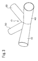
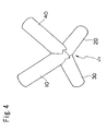
- FIGS. 3 and 4 show a joint structure J 1 further connecting the third pipe 30 and the fourth pipe 40 to the joined portion between the first pipe 10 and the second pipe 20.
- FIG. 3 is a view looking down on the joint structure J 1 from above, while FIG. 4 is a view looking up on the joint structure J 1 from below.
- the joint structure J 1 can be formed in which the four pipes are joined at one location.
- FIG. 5 shows a structure for joining the third pipe 30 and the fourth pipe 40 to the first pipe 10 and the second pipe 20 joined together.
- the third pipe 30 has a joined end face 31 obtained by laser machining into the shape corresponding to outer circumferential surfaces of the joined first pipe 10 and the second pipe 20. And two tenons 32 are provided protruding from this joined end face 31. On the joined end face 31, projections 34 and recesses 33 corresponding to the joined end face of the other face to be joined are formed.
- the third pipe 30 can be joined to the joint portion of the first pipe 10 and the second pipe 20.
- the joined end face 31 of the third pipe 30 is joined in the surface contact state with the outer circumferential surface of the first pipe 10 and the outer circumferential surface of the second pipe 20.
- the fourth pipe 40 also has a joined end face 41 and two tenons 42 obtained by laser machining into the same shape as that of the joined end face 31 of the third pipe 30.
- the fourth pipe 40 can be joined.
- the joined end face 41 of the fourth pipe 40 is joined in the surface contact state with the outer circumferential surface of the first pipe 10 and the outer circumferential surface of the second pipe 20.
- FIG. 6 shows a state where the two tenons 42 of the fourth pipe 40 are opposed to the corresponding mortice 13 of the first pipe 10 and the corresponding mortice 23 of the second pipe 20.
- such a joint structure can be constructed that the ends of the four pipes are collected and joined at one location.
- Point welding or the like may be performed on the joined end face as necessary to obtain a firm joint structure.
Landscapes
- Engineering & Computer Science (AREA)
- General Engineering & Computer Science (AREA)
- Mechanical Engineering (AREA)
- Joining Of Building Structures In Genera (AREA)
- Mutual Connection Of Rods And Tubes (AREA)
- Laser Beam Processing (AREA)
Abstract
Description
- The present invention relates to a joint structure of a pipe.
- FIG. 7 is a perspective view showing a conventional joint structure of a pipe, and FIG. 8 is a block diagram of parts.
- In the conventional joint structure for connecting ends of four pipes to each other, for example, a pipe 1, a
pipe 2, apipe 3 and apipe 4 are prepared and ajoint member 5 is prepared as a separate member, and after each of the pipes are abutted to thejoint member 5, welding W1 is performed at joined portions to join them. - That is, it is structurally difficult to directly join the ends of the four pipes to each other, and the
joint member 5 is required. Thisjoint member 5 is made by forging of a steel material, for example. - For welding to be conducted at the joined portion, beveling machining is needed on the pipes and the joint member.
- The joint structure of a pipe structure is disclosed in
Japanese Patent Laid-Open Publication No. 05-295800 Japanese Patent Laid-Open Publication No. 2001-165126 - Use of a joint member was indispensable in the above-mentioned conventional structure.
- Therefore, an object of the present invention is to provide a joint structure of a pipe which can directly join ends of a plurality of pipes.
- In order to achieve the above object, the joint structure of a pipe of the present invention comprises a tenon formed on a joined end face of a first pipe and a mortice formed on a joined end face of a second pipe, and the joined end face of the first pipe and the joined end face of the second pipe are in surface contact and joined to each other by fitting the tenon and the mortice with each other.
- Moreover, the plurality of pipes provided with the mortice formed on the outer circumferential surface of the first pipe, the mortice formed on the outer circumferential surface of the second pipe, and tenons formed on the joined end faces are brought into surface contact with the outer circumferences of the first pipe and the second pipe and joined to each other by fitting the tenons to the mortice of the first pipe and the mortice of the second pipe.
- Also, the joined end face of the pipe, the tenon and the mortice are formed by laser machining.
- The joint structure of a pipe of the present invention is provided with the above means and ends of a plurality of pipes can be collected at one location and joined to each other without requiring a joint member. Thus, the entire structure can be constructed with a light weight, and the number of processes required for assembling can be drastically reduced.
- Moreover, since the end faces of the pipes are joined to the other party in surface contact, a joint structure with high rigidity can be obtained.
-
- FIG. 1 is a perspective view showing a joint structure of two pipes;
- FIG. 2 is an explanatory view showing the detail of the joint structure of the two pipes;
- FIG. 3 is a perspective view showing a joint structure of four pipes;
- FIG. 4 is a perspective view showing a joint structure of four pipes;
- FIG. 5 is an explanatory view showing the detail of the joint structure in FIG. 3;
- FIG. 6 is an explanatory view showing the detail of the joint structure in FIG. 3;
- FIG. 7 is an explanatory view showing a conventional joint structure of a pipe; and
- FIG. 8 is an explanatory view showing a conventional joint structure of a pipe.
- FIG. 1 is a perspective view showing a joint structure of a pipe of the present invention, and FIG. 2 is an explanatory view showing the detail of a joint portion.
- As shown in FIG. 1, a
first pipe 10 and asecond pipe 20 are directly joined to each other at their ends. And both thepipes - As shown in FIG. 2, the
first pipe 10 has a joined end face 11 obtained by laser machining at a predetermined angle to an axis andtenons 12 projecting from the joined end face 11. In this preferred embodiment, the number oftenons 12 is 2, but the number, location and the like of the tenons may be selected as appropriate. - On a periphery of the
first pipe 10,mortices 13 for receiving tenons of a third pipe and a fourth pipe, which will be described later, are provided. - The
second pipe 20 has a joinedend face 21 obtained by laser machining at a predetermined angle to an axis and amortice 22 cut from the joinedend face 21. Thismortice 22 has a shape in which thetenon 12 of the first pipe is fitted, and the position of themortice 22 is also formed by precision laser machining at a position corresponding to that of thetenon 12. - On the periphery of the
second pipe 20,mortices 23 to which the tenons of the third pipe and the fourth pipe are fitted are also provided. - The joined end face 11 of the
first pipe 10 and the joined end face of thesecond pipe 20 are in surface contact over the entire thickness of the pipes, and thefirst pipe 10 and thesecond pipe 20 are joined to each other by fitting thetenons 12 into themortices 22. - FIGS. 3 and 4 show a joint structure J1 further connecting the
third pipe 30 and thefourth pipe 40 to the joined portion between thefirst pipe 10 and thesecond pipe 20. - FIG. 3 is a view looking down on the joint structure J1 from above, while FIG. 4 is a view looking up on the joint structure J1 from below. The joint structure J1 can be formed in which the four pipes are joined at one location.
- FIG. 5 shows a structure for joining the
third pipe 30 and thefourth pipe 40 to thefirst pipe 10 and thesecond pipe 20 joined together. - The
third pipe 30 has a joinedend face 31 obtained by laser machining into the shape corresponding to outer circumferential surfaces of the joinedfirst pipe 10 and thesecond pipe 20. And twotenons 32 are provided protruding from this joinedend face 31. On the joinedend face 31,projections 34 andrecesses 33 corresponding to the joined end face of the other face to be joined are formed. - By fitting the
tenon 32 of thethird pipe 30 to themortice 13 of the joinedfirst pipe 10 and themortice 23 of the joined second pipe 20 (both are provided on the back side of the figure), thethird pipe 30 can be joined to the joint portion of thefirst pipe 10 and thesecond pipe 20. - The joined
end face 31 of thethird pipe 30 is joined in the surface contact state with the outer circumferential surface of thefirst pipe 10 and the outer circumferential surface of thesecond pipe 20. - The
fourth pipe 40 also has a joinedend face 41 and twotenons 42 obtained by laser machining into the same shape as that of the joinedend face 31 of thethird pipe 30. - And by fitting the two
tenons 42 to themortice 13 of thefirst pipe 10 and themortice 23 of thesecond pipe 20, thefourth pipe 40 can be joined. - The joined
end face 41 of thefourth pipe 40 is joined in the surface contact state with the outer circumferential surface of thefirst pipe 10 and the outer circumferential surface of thesecond pipe 20. - FIG. 6 shows a state where the two
tenons 42 of thefourth pipe 40 are opposed to thecorresponding mortice 13 of thefirst pipe 10 and thecorresponding mortice 23 of thesecond pipe 20. - According to the present invention, as mentioned above, such a joint structure can be constructed that the ends of the four pipes are collected and joined at one location.
- Point welding or the like may be performed on the joined end face as necessary to obtain a firm joint structure.
Claims (3)
- A joint structure of a pipe comprising a tenon formed on a joined end face of a first pipe and a mortice formed on a joined end face of a second pipe, and
wherein the joined end face of the first pipe and the joined end face of the second pipe are in the surface contact and joined to each other by fitting the tenon to the mortice. - The joint structure of a pipe according to claim 1, further comprising a mortice formed on an outer circumferential surface of a first pipe and a mortice formed on an outer circumferential surface of a second pipe, and
wherein a plurality of pipes having tenons on joined end faces are in surface contact with the outer circumferential surfaces of the first pipe and the second pipe and joined to each other by fitting the tenons in the mortice of the first pipe and the mortice of the second pipe. - The joint structure of a pipe according to claim 1, wherein the joined end face of the pipe, the tenon and the mortice are formed by laser machining.
Applications Claiming Priority (1)
| Application Number | Priority Date | Filing Date | Title |
|---|---|---|---|
| JP2005301233A JP2007107675A (en) | 2005-10-17 | 2005-10-17 | Joint structure of pipes |
Publications (2)
| Publication Number | Publication Date |
|---|---|
| EP1775481A1 true EP1775481A1 (en) | 2007-04-18 |
| EP1775481B1 EP1775481B1 (en) | 2008-12-24 |
Family
ID=37622139
Family Applications (1)
| Application Number | Title | Priority Date | Filing Date |
|---|---|---|---|
| EP06405404A Active EP1775481B1 (en) | 2005-10-17 | 2006-09-27 | Joint structure of pipe |
Country Status (5)
| Country | Link |
|---|---|
| US (1) | US7717640B2 (en) |
| EP (1) | EP1775481B1 (en) |
| JP (1) | JP2007107675A (en) |
| CN (1) | CN100560991C (en) |
| DE (1) | DE602006004415D1 (en) |
Cited By (2)
| Publication number | Priority date | Publication date | Assignee | Title |
|---|---|---|---|---|
| WO2015026659A1 (en) * | 2013-08-20 | 2015-02-26 | Illinois Tool Works Inc. | Tubular frame structure and related method of construction |
| GB2486469B (en) * | 2010-12-15 | 2017-02-01 | Mace Jason | Marquee transportable by car or small van |
Families Citing this family (7)
| Publication number | Priority date | Publication date | Assignee | Title |
|---|---|---|---|---|
| US10094496B2 (en) * | 2013-03-12 | 2018-10-09 | Richard Humm | Welded fencing system with prefabricated connectors |
| US9815145B2 (en) | 2014-10-31 | 2017-11-14 | Bombardier Recreational Products Inc. | Frame assembly for a vehicle |
| CN109843709B (en) * | 2016-08-15 | 2021-03-12 | 庞巴迪动力产品公司 | frame assembly for vehicle |
| JP7202137B2 (en) * | 2018-10-19 | 2023-01-11 | コクヨ株式会社 | Frame connection structure and furniture with top plate |
| CN111468838B (en) * | 2020-05-06 | 2022-03-18 | 广东宏石激光技术股份有限公司 | Corner splicing method for cutting rectangular pipe by laser cutting machine |
| CN113070647A (en) * | 2021-04-13 | 2021-07-06 | 曹喜国 | Method for reinforcing mortise and tenon structure in cold-bending right-angle refined steel square-through cavity |
| US12442475B2 (en) | 2025-03-13 | 2025-10-14 | Xiamen Tongjie Technology., Ltd | Push type conduit joint release structure |
Citations (6)
| Publication number | Priority date | Publication date | Assignee | Title |
|---|---|---|---|---|
| GB1189303A (en) * | 1966-07-23 | 1970-04-22 | Arnex Products Ltd | Improvements relating to Joints Between Elongated Metal Members |
| DE2310375A1 (en) * | 1973-03-02 | 1974-09-05 | Otto Lehmann | DETACHABLE PIPE END CONNECTION |
| US4099887A (en) * | 1977-07-18 | 1978-07-11 | Einhard Mackenroth | Structural joints |
| EP0355253A2 (en) * | 1988-08-16 | 1990-02-28 | Takenaka Corporation | Flat solid truss using square steel pipes |
| DE20206222U1 (en) * | 2002-04-19 | 2002-08-22 | Tollenaar Staalgroep B.V., Zwolle | Corner connection of pipe elements |
| DE10324153A1 (en) * | 2003-05-22 | 2004-12-09 | Oelschläger Metalltechnik GmbH | Plug-in connection has two sections each having locking element which in assembled position interact to form positively locking connection, and each have connecting element also forming positively locking connection |
Family Cites Families (23)
| Publication number | Priority date | Publication date | Assignee | Title |
|---|---|---|---|---|
| US616073A (en) * | 1898-12-20 | Crank-hanger | ||
| US603244A (en) * | 1898-05-03 | Flush joint for tubular-fram e constructions | ||
| US1450935A (en) * | 1918-12-12 | 1923-04-10 | Air Reduction | Permanent joint in fabricated form and method of maxing the same |
| US1867226A (en) * | 1929-07-16 | 1932-07-12 | Martin James | Frame-like structure for vehicles, aircraft, and other conveyers |
| US1972309A (en) * | 1932-08-17 | 1934-09-04 | Standard Gas Equipment Corp | Metal tubular frame structure and method of fabricating the same |
| GB855161A (en) * | 1958-05-07 | 1960-11-30 | Norman Cycles Ltd | Improvements relating to the manufacture of cycle frames and like structures |
| US3751792A (en) * | 1971-06-23 | 1973-08-14 | Gazer Corp | Method of forming a welded joint construction |
| JPS576648Y2 (en) * | 1977-08-31 | 1982-02-08 | ||
| DE8202245U1 (en) * | 1982-01-29 | 1982-05-13 | Reisbeck, Günter, 7270 Nagold | FRAME CONSTRUCTION, ESPECIALLY FOR FURNITURE |
| JPS62101735A (en) * | 1985-10-28 | 1987-05-12 | 清水建設株式会社 | Connection structure of steel pipe pillar |
| US5249818A (en) * | 1991-07-26 | 1993-10-05 | Cannondale Corporation | Method of making frames from tubular members and frames made by the method |
| JPH05295800A (en) | 1992-04-16 | 1993-11-09 | Nippon Steel Corp | Pipe joint structure |
| US5190207A (en) * | 1992-06-02 | 1993-03-02 | Deere & Company | Method for welding rectangular tubes |
| GB9319260D0 (en) * | 1993-09-17 | 1993-11-03 | Raleigh Industries Ltd | A frame and method of making it |
| US5595203A (en) * | 1995-06-26 | 1997-01-21 | Espinosa; Mark A. | Stressed arch structures |
| US5700102A (en) * | 1996-02-20 | 1997-12-23 | Feleppa; Richard | Shelter frame connector system |
| US6391414B1 (en) * | 1997-03-07 | 2002-05-21 | Pharmacia Ab | Structure and method for joining parts |
| US6079181A (en) * | 1997-08-27 | 2000-06-27 | Ingersoll-Rand Company | Wall construction |
| AU3808199A (en) * | 1998-06-02 | 1999-12-20 | Elpatronic A.G. | Method for forming a sheet metal assembly and corresponding device and sheet metal set |
| US6085481A (en) * | 1998-10-02 | 2000-07-11 | Lee; Ming-Kun | Grille for a door or window |
| JP3615422B2 (en) * | 1999-03-30 | 2005-02-02 | 富士機器工業株式会社 | Hollow metal pipe assembly structure and assembly method |
| JP3326558B2 (en) | 1999-12-03 | 2002-09-24 | 矢崎化工株式会社 | Joint |
| US7337791B1 (en) * | 2004-04-20 | 2008-03-04 | Belanger, Inc. | Rollover car wash for large vehicles |
-
2005
- 2005-10-17 JP JP2005301233A patent/JP2007107675A/en active Pending
-
2006
- 2006-09-27 EP EP06405404A patent/EP1775481B1/en active Active
- 2006-09-27 DE DE602006004415T patent/DE602006004415D1/en active Active
- 2006-10-05 US US11/538,834 patent/US7717640B2/en active Active
- 2006-10-11 CN CNB2006101423761A patent/CN100560991C/en not_active Expired - Fee Related
Patent Citations (6)
| Publication number | Priority date | Publication date | Assignee | Title |
|---|---|---|---|---|
| GB1189303A (en) * | 1966-07-23 | 1970-04-22 | Arnex Products Ltd | Improvements relating to Joints Between Elongated Metal Members |
| DE2310375A1 (en) * | 1973-03-02 | 1974-09-05 | Otto Lehmann | DETACHABLE PIPE END CONNECTION |
| US4099887A (en) * | 1977-07-18 | 1978-07-11 | Einhard Mackenroth | Structural joints |
| EP0355253A2 (en) * | 1988-08-16 | 1990-02-28 | Takenaka Corporation | Flat solid truss using square steel pipes |
| DE20206222U1 (en) * | 2002-04-19 | 2002-08-22 | Tollenaar Staalgroep B.V., Zwolle | Corner connection of pipe elements |
| DE10324153A1 (en) * | 2003-05-22 | 2004-12-09 | Oelschläger Metalltechnik GmbH | Plug-in connection has two sections each having locking element which in assembled position interact to form positively locking connection, and each have connecting element also forming positively locking connection |
Cited By (2)
| Publication number | Priority date | Publication date | Assignee | Title |
|---|---|---|---|---|
| GB2486469B (en) * | 2010-12-15 | 2017-02-01 | Mace Jason | Marquee transportable by car or small van |
| WO2015026659A1 (en) * | 2013-08-20 | 2015-02-26 | Illinois Tool Works Inc. | Tubular frame structure and related method of construction |
Also Published As
| Publication number | Publication date |
|---|---|
| DE602006004415D1 (en) | 2009-02-05 |
| US20080012311A1 (en) | 2008-01-17 |
| CN1952414A (en) | 2007-04-25 |
| JP2007107675A (en) | 2007-04-26 |
| CN100560991C (en) | 2009-11-18 |
| US7717640B2 (en) | 2010-05-18 |
| EP1775481B1 (en) | 2008-12-24 |
Similar Documents
| Publication | Publication Date | Title |
|---|---|---|
| EP3589854B1 (en) | Flexural pivot | |
| US7717640B2 (en) | Joint structure of pipe | |
| US7918008B2 (en) | Method of manufacturing column and bed of machine tool | |
| CN103249901A (en) | Steel pipe stiffening brace and production method therefor | |
| JPS61152987A (en) | Manufacture of rotor for rotary fluid pump | |
| JP2790286B2 (en) | Joining structure of annular parts | |
| US9156110B2 (en) | Weldment with isolation pocket for reduction of weld-induced distortion | |
| CN101128675A (en) | Sliding bearings, application and manufacture of sliding bearings | |
| JP4863783B2 (en) | Steel pipe joint structure and steel pipe joining method | |
| JP3137053U (en) | Temporary assembly structure | |
| US10151383B2 (en) | Braze retention feature for a carrier assembly | |
| JP6514965B2 (en) | Washer and method of manufacturing washer | |
| JP2008305649A (en) | Multilayer hinge for unit box of fuel cell | |
| JP4589100B2 (en) | Connecting structure with knock pin | |
| JP6710067B2 (en) | Pin joint structure, pin joint jig, and pin joint method | |
| JPH0711906A (en) | Method for manufacturing steam turbine diaphragm | |
| JPH0959971A (en) | Joint structure of pile | |
| EP1672227B1 (en) | Mechanical device comprising several pieces assembled in relatively precise positions | |
| JP3220229U (en) | Multifunction joint structure that can be quickly, stably and accurately fitted | |
| JP6704768B2 (en) | Friction stir welding method | |
| JP3163334U (en) | Backing metal for welding | |
| JP3168839U (en) | Welding backing | |
| JP4391361B2 (en) | Steel segment manufacturing method | |
| JP2009127696A (en) | Connecting rod and its manufacturing method | |
| JP2003286718A (en) | Backing ring for joints of steel pipes for structures |
Legal Events
| Date | Code | Title | Description |
|---|---|---|---|
| PUAI | Public reference made under article 153(3) epc to a published international application that has entered the european phase |
Free format text: ORIGINAL CODE: 0009012 |
|
| AK | Designated contracting states |
Kind code of ref document: A1 Designated state(s): AT BE BG CH CY CZ DE DK EE ES FI FR GB GR HU IE IS IT LI LT LU LV MC NL PL PT RO SE SI SK TR |
|
| AX | Request for extension of the european patent |
Extension state: AL BA HR MK YU |
|
| 17P | Request for examination filed |
Effective date: 20070529 |
|
| RAP1 | Party data changed (applicant data changed or rights of an application transferred) |
Owner name: YAMAZAKI MAZAK CORPORATION |
|
| 17Q | First examination report despatched |
Effective date: 20070905 |
|
| AKX | Designation fees paid |
Designated state(s): DE FR GB IT |
|
| GRAP | Despatch of communication of intention to grant a patent |
Free format text: ORIGINAL CODE: EPIDOSNIGR1 |
|
| GRAS | Grant fee paid |
Free format text: ORIGINAL CODE: EPIDOSNIGR3 |
|
| GRAS | Grant fee paid |
Free format text: ORIGINAL CODE: EPIDOSNIGR3 |
|
| GRAA | (expected) grant |
Free format text: ORIGINAL CODE: 0009210 |
|
| AK | Designated contracting states |
Kind code of ref document: B1 Designated state(s): DE FR GB IT |
|
| REG | Reference to a national code |
Ref country code: GB Ref legal event code: FG4D |
|
| REF | Corresponds to: |
Ref document number: 602006004415 Country of ref document: DE Date of ref document: 20090205 Kind code of ref document: P |
|
| PLBE | No opposition filed within time limit |
Free format text: ORIGINAL CODE: 0009261 |
|
| STAA | Information on the status of an ep patent application or granted ep patent |
Free format text: STATUS: NO OPPOSITION FILED WITHIN TIME LIMIT |
|
| 26N | No opposition filed |
Effective date: 20090925 |
|
| REG | Reference to a national code |
Ref country code: FR Ref legal event code: PLFP Year of fee payment: 11 |
|
| REG | Reference to a national code |
Ref country code: FR Ref legal event code: PLFP Year of fee payment: 12 |
|
| REG | Reference to a national code |
Ref country code: FR Ref legal event code: PLFP Year of fee payment: 13 |
|
| PGFP | Annual fee paid to national office [announced via postgrant information from national office to epo] |
Ref country code: DE Payment date: 20250805 Year of fee payment: 20 |
|
| PGFP | Annual fee paid to national office [announced via postgrant information from national office to epo] |
Ref country code: IT Payment date: 20250825 Year of fee payment: 20 |
|
| PGFP | Annual fee paid to national office [announced via postgrant information from national office to epo] |
Ref country code: GB Payment date: 20250807 Year of fee payment: 20 |
|
| PGFP | Annual fee paid to national office [announced via postgrant information from national office to epo] |
Ref country code: FR Payment date: 20250808 Year of fee payment: 20 |
|
| REG | Reference to a national code |
Ref country code: DE Ref legal event code: R082 Ref document number: 602006004415 Country of ref document: DE Representative=s name: MAUCHER JENKINS PATENTANWAELTE & RECHTSANWAELT, DE |