EP1775436A1 - Exhaust system - Google Patents
Exhaust system Download PDFInfo
- Publication number
- EP1775436A1 EP1775436A1 EP06255280A EP06255280A EP1775436A1 EP 1775436 A1 EP1775436 A1 EP 1775436A1 EP 06255280 A EP06255280 A EP 06255280A EP 06255280 A EP06255280 A EP 06255280A EP 1775436 A1 EP1775436 A1 EP 1775436A1
- Authority
- EP
- European Patent Office
- Prior art keywords
- exhaust
- pipe section
- partition plate
- projection
- exhaust system
- Prior art date
- Legal status (The legal status is an assumption and is not a legal conclusion. Google has not performed a legal analysis and makes no representation as to the accuracy of the status listed.)
- Granted
Links
Images


Classifications
-
- F—MECHANICAL ENGINEERING; LIGHTING; HEATING; WEAPONS; BLASTING
- F01—MACHINES OR ENGINES IN GENERAL; ENGINE PLANTS IN GENERAL; STEAM ENGINES
- F01N—GAS-FLOW SILENCERS OR EXHAUST APPARATUS FOR MACHINES OR ENGINES IN GENERAL; GAS-FLOW SILENCERS OR EXHAUST APPARATUS FOR INTERNAL-COMBUSTION ENGINES
- F01N13/00—Exhaust or silencing apparatus characterised by constructional features
- F01N13/08—Other arrangements or adaptations of exhaust conduits
- F01N13/10—Other arrangements or adaptations of exhaust conduits of exhaust manifolds
-
- F—MECHANICAL ENGINEERING; LIGHTING; HEATING; WEAPONS; BLASTING
- F01—MACHINES OR ENGINES IN GENERAL; ENGINE PLANTS IN GENERAL; STEAM ENGINES
- F01N—GAS-FLOW SILENCERS OR EXHAUST APPARATUS FOR MACHINES OR ENGINES IN GENERAL; GAS-FLOW SILENCERS OR EXHAUST APPARATUS FOR INTERNAL-COMBUSTION ENGINES
- F01N13/00—Exhaust or silencing apparatus characterised by constructional features
- F01N13/08—Other arrangements or adaptations of exhaust conduits
-
- F—MECHANICAL ENGINEERING; LIGHTING; HEATING; WEAPONS; BLASTING
- F01—MACHINES OR ENGINES IN GENERAL; ENGINE PLANTS IN GENERAL; STEAM ENGINES
- F01N—GAS-FLOW SILENCERS OR EXHAUST APPARATUS FOR MACHINES OR ENGINES IN GENERAL; GAS-FLOW SILENCERS OR EXHAUST APPARATUS FOR INTERNAL-COMBUSTION ENGINES
- F01N13/00—Exhaust or silencing apparatus characterised by constructional features
- F01N13/18—Construction facilitating manufacture, assembly, or disassembly
-
- F—MECHANICAL ENGINEERING; LIGHTING; HEATING; WEAPONS; BLASTING
- F01—MACHINES OR ENGINES IN GENERAL; ENGINE PLANTS IN GENERAL; STEAM ENGINES
- F01N—GAS-FLOW SILENCERS OR EXHAUST APPARATUS FOR MACHINES OR ENGINES IN GENERAL; GAS-FLOW SILENCERS OR EXHAUST APPARATUS FOR INTERNAL-COMBUSTION ENGINES
- F01N2240/00—Combination or association of two or more different exhaust treating devices, or of at least one such device with an auxiliary device, not covered by indexing codes F01N2230/00 or F01N2250/00, one of the devices being
- F01N2240/20—Combination or association of two or more different exhaust treating devices, or of at least one such device with an auxiliary device, not covered by indexing codes F01N2230/00 or F01N2250/00, one of the devices being a flow director or deflector
-
- F—MECHANICAL ENGINEERING; LIGHTING; HEATING; WEAPONS; BLASTING
- F01—MACHINES OR ENGINES IN GENERAL; ENGINE PLANTS IN GENERAL; STEAM ENGINES
- F01N—GAS-FLOW SILENCERS OR EXHAUST APPARATUS FOR MACHINES OR ENGINES IN GENERAL; GAS-FLOW SILENCERS OR EXHAUST APPARATUS FOR INTERNAL-COMBUSTION ENGINES
- F01N2260/00—Exhaust treating devices having provisions not otherwise provided for
- F01N2260/18—Exhaust treating devices having provisions not otherwise provided for for improving rigidity, e.g. by wings, ribs
Definitions
- the present invention relates to an exhaust system and particularly, but not exclusively, to an exhaust system for an internal combustion engine in which a partition plate is provided in an integrating exhaust pipe section to avoid exhaust interference in a multi-cylinder internal combustion engine. Aspects of the invention also relate to a method and to a vehicle.
- an exhaust system in a inline four cylinder internal combustion engine, includes upstream side exhaust branch passages that are joined so as to be in a so-called "4-2-1" form by dividing the inside of the integrating exhaust pipe section into two pathways by the partition plate, connecting upstream side exhaust branch passages for cylinders # 1 and #4 to a first pathway, and upstream side exhaust branch passages for cylinders #2 and #3 to a second pathway.
- an upstream side end portion of the partition plate is fixed to and supported with an upstream side exhaust branch passage (such as pipes).
- a downstream side end portion of the partition plate includes a non-connected or a free end within the integrating exhaust pipe section. Since the end is free, it tends to vibrate so that undesirable noise may be generated.
- a curved portion is provided in a longitudinal direction of the partition plate, positioned generally at the center of the partition plate ' when measured with respect to the width direction. In such a structure, however, the rigidity of the partition plate becomes low and it further tends to vibrate, causing noise.
- an exhaust system for an internal combustion engine having a plurality cylinders comprising a plurality of exhaust branch passages that are each in communication with at least one of the cylinders, an intermediate exhaust pipe section forming a passage that is in communication with the exhaust branch passages, wherein the intermediate exhaust pipe section has an axis generally curved in an exhaust flow direction, a partition plate provided in the intermediate exhaust pipe section, wherein the partition plate is curved to generally correspond to the axis of the intermediate exhaust pipe section, wherein the partition plate separates the passage into a first flow path that is in communication with at least two exhaust branch passages and a second flow path that is in communication with at least two other exhaust branch passages and a downstream pipe section which is connected to the intermediate exhaust pipe section and forms a merged passage that is communication with the first and second flow paths and wherein the partition plate has a first projection positioned on a surface thereof such that the projection is positioned in the first flow path, and wherein the projection is oriented so as to extend in a
- the first flow path is an outside path.
- the partition plate comprises metal and the projection is integrally formed thereon by press-molding.
- the projection is formed by a first reinforcement member being attached to the surface of the partition plate and wherein the surface is oriented to face the first flow path when the partition plate is positioned within the intermediate exhaust pipe section.
- the exahust system may further comprise a second reinforcement member that is attached to the same surface of the partition plate as the first reinforcement member and wherein the second reinforcement member is oriented so as to extend in the same direction as the first reinforcement member.
- the partition plate further comprises a cut-out portion extending inwardly from an outside edge thereof.
- the cut-out portion is positioned adjacent the first and second reinforcement members.
- the exhaust branch passages are formed by a plurality of upstream pipes.
- An upstream end of the partition plate may be fixed to a portion of the upstream pipe.
- a downstream end of the partition plate may be a free end positioned in the merged passage.
- the first projection is formed closer to a downstream end of the partition plate than an upstream end of the partition plate.
- the partition plate further comprises a second projection formed on the same surface of the partition plate as the first projection such that the second projection is positioned in the first flow path, and wherein the second projection is oriented so as to extend substantially in the same direction as the exhaust flow.
- the partition plate further comprises a cut-out portion extending inwardly from an outside edge thereof.
- the second projection is located adjacent to the cut-out portion.
- the exhaust system may comprise a restraint member that supports a downstream end of the partition plate.
- the partition plate further comprises a first recess formed therein and the restraint member further comprises a second recess formed therein.
- the second recess of the restraint member may engage the first recess of the partition plate.
- one of the partition plate and the restraint member further comprises a recess formed therein and an edge of the other of the partition plate and the restraint member is received within the recess.
- an exhaust system for an internal combustion engine having a plurality of cylinders comprising: a plurality of exhaust branch passages communication with the cylinders of the exhaust system respectively, an intermediate exhaust passage section that is in communication with the exhaust branch passages, a partition plate that has a shape that generally corresponds to an axis extending through the intermediate passage section, where the partition plate is provided in the intermediate exhaust passage section to divide the intermediate passage section into first and second flow passages, and a merged passage that is in communication with the intermediate exhaust passage section, wherein a first projection that is oriented so as to extend generally perpendicular to the direction of exhaust flow is positioned on a first surface of the partition plate and the partition plate is oriented such that the first surface is oriented to be facing the first flow path.
- a second projection is positioned on the first surface of the partition plate.
- the second projection is positioned so as to extend in a direction that is generally perpendicular to the first projection.
- the second projection is positioned so as to extend in a direction that is generally parallel to the first projection.
- the first projection is a bead that is integrally formed in the partition plate.
- the first projection is a reinforcement member that is fixedly attached to the partition plate.
- an exhaust system for an internal combustion engine having a plurality of cylinders comprising a plurality of exhaust branch means that are in communication with the cylinders of the internal combustion engine, passage means for delivering exhaust from the cylinders such that the passage means are in communication with the exhaust branch means, and wherein the passage means has an axis that is generally curved in an exhaust flow direction, a partition means provided in the passage means, wherein the partition means is curved to substantially correspond to the axis of the passage means and wherein the partition means separates the passage means into a first flow path that is in communication with at least two exhaust branch means and a second flow path that is in communication with at least two other exhaust branch means and a downstream passage means for forming a merged passage that is in communication with the first and second flow paths, wherein the partition means has projection means for reducing vibration of the partition means and wherein the partition means is oriented so as to position the projection means in the first flow path, and wherein at least a portion of the projection means
- a method of minimizing vibration in an exhaust system having a plurality of cylinders comprising providing an exhaust system that comprises a plurality of exhaust branch passages that are each in communication with at least one cylinder, connecting the plurality of exhaust branch passages to an intermediate exhaust pipe section having a predetermined axis, providing a partition plate that has a shape that generally corresponds to the axis of the intermediate exhaust pipe section, wherein the partition plate is further provided with a first projection thereon on a predetermined surface of the partition plate, wherein the projection is oriented in a direction that is generally perpendicular to exhaust flow, securing the partition plate within the intermediate exhaust pipe section so as to divide the intermediate exhaust pipe section into a first flow path and a second flow path such that the partition plate is oriented so that the predetermined surface of the partition plate that includes the projection is facing the first flow path and connecting an end of the intermediate exhaust pipe section downstream of the partition plate to a downstream pipe section that defines a merged passageway.
- an internal combustion engine having a plurality of cylinders comprises a plurality of exhaust branch passages, an intermediate exhaust pipe section, a partition plate, and a downstream pipe section.
- Each exhaust branch passage is in communication with a respective cylinder.
- the intermediate exhaust pipe section forms a passage that is in communication with the exhaust branch passages.
- the partition plate is provided in the intermediate passage and divides the intermediate passage into first and second flow paths.
- the partition plate further includes a projection positioned on a first surface thereof that is oriented so as to be generally perpendicular to the direction of exhaust flow. The partition plate is disposed within the intermediate passage so as to position the projection in the first flow path.
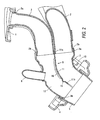
- FIGS. 1 and 2 illustrate an embodiment of an exhaust manifold for a inline four cylinder internal combustion engine.
- An upstream end 2a of an upstream side exhaust branch passage 2 (such as, e.g., a pipe) is connected to a cylinder head attachment flange 1.
- the cylinder head attachment flange 1 is attached to a side of the cylinder head (not shown). While it is contemplated that each side exhaust branch passage 2 is made from metal, it is also within the scope of the invention that the side exhaust branch passages 2 may be made from material other than metal.
- the four (4) upstream side exhaust branch passages 2 shown in the embodiment of Fig. 1 and 2 extend toward approximately the center of the cylinder line of the exhaust manifold, and downstream side ends 2b thereof extend generally in parallel to each other near an entrance of an integrating exhaust pipe section 3.
- the upstream side exhaust branch passages 2 are combined in a complementary fashion, respectively, and connected and secured to the entrance of the integrating exhaust pipe section 3.
- the downstream side ends 2b of the upstream side exhaust branch passages 2 each have a generally quadrant shape in cross-section, respectively, so when the downstream side ends 2b are combined in a complementary fashion, the combined downstream side ends 2b form a generally circular-type shape in cross-section near the entrance of the integrating exhaust pipe section 3.
- downstream side ends 2b are inserted into and secured to an interior surface of the upstream side end 3a of the integrating exhaust pipe section 3.
- the downstream side ends 2b may be secured to the interior surface side end 3a of the integrating exhaust pipe section 3 by welding.
- the upstream side exhaust branch passages 2 each extend from the cylinder head attachment flange 1 in an approximately horizontal direction, and then curve by approximately ninety (90) degrees downwardly therefrom, so that the upstream side exhaust branch passage 2 is connected to the integrating exhaust pipe section 3. It is understood, however, that the specific curve angle for the upstream side exhaust branch passages 2 is not limited that which is described above and, in fact, may be any angle.
- the upstream side exhaust branch passages 2 for the cylinders #2 and #3 are disposed below the upstream side exhaust branch passages for the cylinders #1 and #4, such that the exhaust branch passages 2 are arranged in an overlapping manner.
- the specific positions of the upstream side exhaust branch passages 2 may differ from what is described above without departing from the invention.
- the upstream side end portion 3a of the integrating pipe section 3 has an opening, in which the four (4) downstream side ends 2b of the upstream side exhaust branch passages 2 are inserted, and the opening faces approximately upward as compared to a downstream side end portion 3b.
- the upstream side end portion 3a generally curves toward the engine side.
- the downstream side portion 3b has an opening facing obliquely downward and away from the engine side. That is, when it is viewed from the front or back of the engine, the integrating pipe exhaust section 3 curves in a direction opposite to that of the upstream side exhaust branch passage 2, and as shown in FIG. 2, the exhaust system curves, as a whole, so as to have an approximate S-shape.
- a flange 4 for attaching a catalytic converter (not shown) to the exhaust system may be attached to the downstream side end portion 3b of the integrating exhaust pipe section 3.
- this flange 4 has a generally cylindrical section or downstream pipe section 5 which may be integrally formed with the flange 4 and connected to the integrating exhaust pipe section 3.
- the downstream pipe section 5 is fixedly connected to the downstream side portion 3b of the integrating exhaust pipe section 3 so that an inner face of the downstream pipe section 5 fits around the outer circumference of the downstream side end portion 3b of the integrating exhaust pipe section 3.
- the downstream pipe section 5 defines a merged passageway for exhaust flow.
- an end of an exhaust recirculation pipe 6, which is part of an exhaust recirculation passage, is connected to a side surface of the integrating exhaust pipe section 3 on the cylinder head side, and the other end of this exhaust recirculation pipe 6 is connected to the cylinder head attachment flange 1.
- an air-fuel ratio sensor (not illustrated) may be attached to a side face of the integrating exhaust pipe section 3 on an engine front side thereof.
- a partition plate 11 which in one embodiment may be formed by press-molding a steel plate, is provided inside the above-described integrating exhaust pipe section 3.
- the partition plate 11 has, as shown in Fig. 2, a complementary shape, which curves along an axis of the integrating exhaust pipe section 3, and divides the inner space of the integrating exhaust pipe section 3 into a first flow path 12 in which exhaust gas from the cylinders #2 and #3 flows and, and a second flow path 13 in which exhaust gas from the cylinders #1 and #4 flows.
- An upstream side end portion 11 a of this partition plate 11 is inserted between the downstream side portions 2b of upstream side exhaust branch passages 2 for the cylinders #2 and #3 and the downstream side portions 2b of upstream side exhaust branch passage 2 for the cylinders #1 and #4 and is jointly welded therewith. Moreover, a downstream side end portion 11b of the partition plate 11 extends to a position adjacent a downstream side end portion 3b of the integrating exhaust pipe section 3, which may also be referred to as an outlet edge. Therefore, interference of exhaust gases from the four cylinders joined in the so-called "4-2-1" form that have sequentially ignited, may be avoided. It is understood, however, that the form of the cylinder is not limited to "4-2-1" form but may be other forms, as well.
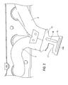
- a first bead 15 is positioned adjacent to the downstream side end portion 11b of the partition plate 11, as best seen in Fig. 3.
- the first bead 15 extends in a direction that is generally perpendicular to the exhaust flow that flows through the integrating exhaust pipe section 3.
- the first bead 15 is formed as a projection that extends outwardly from a first surface of the partition plate 11 to minimize vibration.
- the first bead 15 also serves as reinforcement for the partition plate 11.
- a second bead 16 extending substantially in the direction of the flow of the exhaust gas may be further positioned on the upstream side of the first bead 15.
- first and second beads 15 and 16 are partially deformed or bulged outwardly of the first surface of the partition plate 11 by press-molding the partition plate 11.
- the partition plate 11 is oriented within the integrating exhaust pipe section 3 such that the first and second beads 15 and 16 are projected into the first flow path 12 which serves as an outside path of the curve portion.
- a relatively large cut-out portion 17 may be provided for avoiding interference with the air-fuel ratio sensor (not illustrated) that may be connected in one side edge of the partition plate 11.
- the second bead 16 is formed adjacent to the cut-out portion 17 at the approximate center of the remaining portion of the partition plate 11.
- the first bead 15 is formed over a substantial portion of the downstream side end portion 11b of a partition plate 11 in a width direction.
- the rigidity of the partition plate 11 increases, and vibration is controlled by integrally forming the beads 15 and 16 into the partition plate 11 by press molding. Since in the primary vibration mode of the partition plate 11, the partition plate 11 tends to have amplitude in a direction perpendicular to the flow of the exhaust, the inclusion of the first bead 15 in a direction perpendicular to the direction of the exhaust flow effectively suppresses the vibration of the partition plate. More specifically, the first bead 15 is formed in a direction that is generally perpendicular to the direction of the flow of exhaust, so that generation of noise due to the vibration can be prevented. The primary vibration mode of the partition plate 11, which has the amplitude in a direction perpendicular to that of the flow, can be effectively suppressed by the first bead 15.
- the first bead 15 is provided at least closer to a downstream edge, as compared to the upstream edge, and the first bead 15 is located near the downstream side end portion 11b of the partition plate 11, which is a non-connected or a free end, vibration of this downstream side end portion 11b is effectively suppressed.
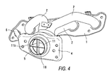
- FIG. 4 shows an embodiment in which a restraint member 18 is provided to more certainly prevent vibration of the downstream side end portion 11 b of the partition plate 11 and provide support for the partition plate 11.
- the restraint member 18 is constructed so as to form an approximately cross shape with the partition plate 11. It is preferred that the restraint member 18 be made from a strip metal plate. It is understood, however, that the restraint member 18 may be made from materials other than the metal.
- the restraint member 18 has a recess or slit located generally at its center.
- the partition plate 11 also includes a mating recess or slit located generally at the center of the end portion thereof.
- the restraint member 18 and the partition plate 11 are assembled together with the slit members of the restraint member 18 and partition plate 11 engaging one another so as to form a cross. After the slit members of the restraint member 18 and the partition plate 11 are secured together to form the cross, the restraint member 18 and the partition plate 11 are welded together, and both ends the restraint member 18 are fixed, such as by welding, to the downstream pipe section 5 which is connected to the integrating exhaust pipe section 3.
- assembly of the restraint member 18 and the partition plate 11 may be accomplished in other suitable manners, without departing from the invention.
- only one of the restraint member 18 and the partition plate 11 includes a slit. An edge of the other one of the restraint member 18 and the partition plate 11 is received in the slit so has to form the cross-shape for a portion of the assembly along its length.
- FIG. 5 shows an example in which in place of forming the first and second beads 15, 16 as projections, rod shaped reinforcement members 19 and 20 are fixed to a surface of the partition plate 11.
- the reinforcement members 19 and 20 may be fixed to the surface of the partition plate 11 by welding or other suitable method of attachment.
- Reinforcement members 19 and 20 are attached to an outer surface of the curved partition plate 11, such that the reinforcement members 19 and 20 will be positioned in the first flow path 12. Therefore, the influence on exhaust flow is minimized in the same general manner as in the embodiment mentioned above that included the first and second beads 15, 16.
- the two reinforcement members 19 and 20 are both provided in a direction that is generally perpendicular to that of the exhaust flow. Further, a cut-out portion, like cut-out portion 17, may be provided between the two reinforcement members 19 and 20.
- an exhaust system that comprises a plurality of exhaust branch passages 2 that are each in communication with a respective cylinder is provided.
- the exhaust branch passages 2 are connected to an intermediate exhaust pipe section 3 that has a predetermined axis that is curved in the direction of exhaust flow.
- a partition plate 11 is provided that has a shape that generally corresponds to the axis of the intermediate exhaust pipe section 3.
- the partition plate 11 is further provided with at least a first projection 15, or 19 positioned on a predetermined surface of the partition plate.
- the first projection 15 or 19 is oriented in a direction that is generally perpendicular to exhaust flow.
- the partition plate 11 is secured within the intermediate exhaust pipe section 3 so as to divide the intermediate exhaust pipe section 3 into first and second flow paths 12, 13, respectively. Further, the partition plate 11 is oriented within the intermediate exhaust pipe section 3 such that the predetermined surface of the partition plate 11 with the at least one projection is facing the first flow path.
- downstream side end portion 3b of the intermediate exhaust pipe section 3 is connected to a downstream pipe section 5 that defines a merged passageway therein.
Landscapes
- Engineering & Computer Science (AREA)
- Chemical & Material Sciences (AREA)
- Combustion & Propulsion (AREA)
- Mechanical Engineering (AREA)
- General Engineering & Computer Science (AREA)
- Exhaust Silencers (AREA)
Abstract
Description
- The present invention relates to an exhaust system and particularly, but not exclusively, to an exhaust system for an internal combustion engine in which a partition plate is provided in an integrating exhaust pipe section to avoid exhaust interference in a multi-cylinder internal combustion engine. Aspects of the invention also relate to a method and to a vehicle.
- As disclosed in
Japanese Patent No. 3405857 cylinders # 1 and #4 to a first pathway, and upstream side exhaust branch passages forcylinders # 2 and #3 to a second pathway. - Generally, in such a partition plate provided in the above described integrating exhaust pipe section, an upstream side end portion of the partition plate is fixed to and supported with an upstream side exhaust branch passage (such as pipes). A downstream side end portion of the partition plate, however, includes a non-connected or a free end within the integrating exhaust pipe section. Since the end is free, it tends to vibrate so that undesirable noise may be generated. As may be seen in
Japanese Patent No. 3405857 - It is an aim of the invention to address this problem and to improve upon known technology. Other aims and advantages of the invention will become apparent from the following description, claims and drawings.
- Aspects of the invention therefore provide an exhaust system, a method and a vehicle as claimed in the appended claims.
- According to another aspect of the invention, there is provided an exhaust system for an internal combustion engine having a plurality cylinders, comprising a plurality of exhaust branch passages that are each in communication with at least one of the cylinders, an intermediate exhaust pipe section forming a passage that is in communication with the exhaust branch passages, wherein the intermediate exhaust pipe section has an axis generally curved in an exhaust flow direction, a partition plate provided in the intermediate exhaust pipe section, wherein the partition plate is curved to generally correspond to the axis of the intermediate exhaust pipe section, wherein the partition plate separates the passage into a first flow path that is in communication with at least two exhaust branch passages and a second flow path that is in communication with at least two other exhaust branch passages and a downstream pipe section which is connected to the intermediate exhaust pipe section and forms a merged passage that is communication with the first and second flow paths and wherein the partition plate has a first projection positioned on a surface thereof such that the projection is positioned in the first flow path, and wherein the projection is oriented so as to extend in a direction that is substantially perpendicular to the direction of exhaust flow.
- In an embodiment, the first flow path is an outside path.
- In an embodiment, the partition plate comprises metal and the projection is integrally formed thereon by press-molding.
- In an embodiment, the projection is formed by a first reinforcement member being attached to the surface of the partition plate and wherein the surface is oriented to face the first flow path when the partition plate is positioned within the intermediate exhaust pipe section.
- The exahust system may further comprise a second reinforcement member that is attached to the same surface of the partition plate as the first reinforcement member and wherein the second reinforcement member is oriented so as to extend in the same direction as the first reinforcement member.
- In an embodiment, the partition plate further comprises a cut-out portion extending inwardly from an outside edge thereof.
- In an embodiment, the cut-out portion is positioned adjacent the first and second reinforcement members.
- In an embodiment, the exhaust branch passages are formed by a plurality of upstream pipes. An upstream end of the partition plate may be fixed to a portion of the upstream pipe. A downstream end of the partition plate may be a free end positioned in the merged passage.
- In an embodiment, the first projection is formed closer to a downstream end of the partition plate than an upstream end of the partition plate.
- In an embodiment, the partition plate further comprises a second projection formed on the same surface of the partition plate as the first projection such that the second projection is positioned in the first flow path, and wherein the second projection is oriented so as to extend substantially in the same direction as the exhaust flow.
- In an embodiment, the partition plate further comprises a cut-out portion extending inwardly from an outside edge thereof.
- In an embodiment, the second projection is located adjacent to the cut-out portion.
- The exhaust system may comprise a restraint member that supports a downstream end of the partition plate.
- In an embodiment, the partition plate further comprises a first recess formed therein and the restraint member further comprises a second recess formed therein. The second recess of the restraint member may engage the first recess of the partition plate.
- In an embodiment, one of the partition plate and the restraint member further comprises a recess formed therein and an edge of the other of the partition plate and the restraint member is received within the recess.
- According to a further aspect of the invention there is provided an exhaust system for an internal combustion engine having a plurality of cylinders, comprising: a plurality of exhaust branch passages communication with the cylinders of the exhaust system respectively, an intermediate exhaust passage section that is in communication with the exhaust branch passages, a partition plate that has a shape that generally corresponds to an axis extending through the intermediate passage section, where the partition plate is provided in the intermediate exhaust passage section to divide the intermediate passage section into first and second flow passages, and a merged passage that is in communication with the intermediate exhaust passage section, wherein a first projection that is oriented so as to extend generally perpendicular to the direction of exhaust flow is positioned on a first surface of the partition plate and the partition plate is oriented such that the first surface is oriented to be facing the first flow path.
- In an embodiment, a second projection is positioned on the first surface of the partition plate.
- In an embodiment, the second projection is positioned so as to extend in a direction that is generally perpendicular to the first projection.
- In an embodiment, the second projection is positioned so as to extend in a direction that is generally parallel to the first projection.
- In an embodiment, the first projection is a bead that is integrally formed in the partition plate.
- In an embodiment, the first projection is a reinforcement member that is fixedly attached to the partition plate.
- According to a still further aspect of the invention there is provided an exhaust system for an internal combustion engine having a plurality of cylinders, comprising a plurality of exhaust branch means that are in communication with the cylinders of the internal combustion engine, passage means for delivering exhaust from the cylinders such that the passage means are in communication with the exhaust branch means, and wherein the passage means has an axis that is generally curved in an exhaust flow direction, a partition means provided in the passage means, wherein the partition means is curved to substantially correspond to the axis of the passage means and wherein the partition means separates the passage means into a first flow path that is in communication with at least two exhaust branch means and a second flow path that is in communication with at least two other exhaust branch means and a downstream passage means for forming a merged passage that is in communication with the first and second flow paths, wherein the partition means has projection means for reducing vibration of the partition means and wherein the partition means is oriented so as to position the projection means in the first flow path, and wherein at least a portion of the projection means is oriented so as to extend in a direction that is substantially perpendicular to the direction of exhaust flow.
- According to yet another aspect of the invention there is provided a method of minimizing vibration in an exhaust system having a plurality of cylinders, comprising providing an exhaust system that comprises a plurality of exhaust branch passages that are each in communication with at least one cylinder, connecting the plurality of exhaust branch passages to an intermediate exhaust pipe section having a predetermined axis, providing a partition plate that has a shape that generally corresponds to the axis of the intermediate exhaust pipe section, wherein the partition plate is further provided with a first projection thereon on a predetermined surface of the partition plate, wherein the projection is oriented in a direction that is generally perpendicular to exhaust flow, securing the partition plate within the intermediate exhaust pipe section so as to divide the intermediate exhaust pipe section into a first flow path and a second flow path such that the partition plate is oriented so that the predetermined surface of the partition plate that includes the projection is facing the first flow path and connecting an end of the intermediate exhaust pipe section downstream of the partition plate to a downstream pipe section that defines a merged passageway.
- For example an internal combustion engine having a plurality of cylinders comprises a plurality of exhaust branch passages, an intermediate exhaust pipe section, a partition plate, and a downstream pipe section. Each exhaust branch passage is in communication with a respective cylinder. The intermediate exhaust pipe section forms a passage that is in communication with the exhaust branch passages. The partition plate is provided in the intermediate passage and divides the intermediate passage into first and second flow paths. The partition plate further includes a projection positioned on a first surface thereof that is oriented so as to be generally perpendicular to the direction of exhaust flow. The partition plate is disposed within the intermediate passage so as to position the projection in the first flow path.
- Within the scope of this application it is envisaged that the various aspects, embodiments and alternatives set out in the preceding paragraphs, in the claims and in the following description may be taken individually or in any combination thereof.
- The present invention will now be described, by way of example only, with reference to the accompanying drawings in which:
- FIG. 1 is a front view of an exhaust manifold for a inline four cylinder combustion engine according to one embodiment of an exhaust system;
- FIG. 2 is a cross-sectional view of an exhaust manifold, taken along line II-II of FIG. 1;
- FIG. 3 is a perspective view of an exhaust manifold, viewed in a direction of arrow B of FIG. 2;
- FIG. 4 is a perspective view of an embodiment of an exhaust manifold in which a restraint member is provided; and
- FIG. 5 is a perspective view of a partition plate used in an embodiment of an exhaust system in which the partition plate includes a reinforcement member.
- While the claims are not limited to the illustrated embodiments, an appreciation of various aspects of the system is best gained through a discussion of various examples thereof. Referring now to the drawings, illustrative embodiments are shown in detail. Although the drawings represent the embodiments, the drawings are not necessarily to scale and certain features may be exaggerated to better illustrate and explain an innovative aspect of an embodiment. Further, the embodiments described herein are not intended to be exhaustive or otherwise limiting or restricting to the precise form and configuration shown in the drawings and disclosed in the following detailed description. Exemplary embodiments of the present invention are described in detail by referring to the drawings.
- FIGS. 1 and 2 illustrate an embodiment of an exhaust manifold for a inline four cylinder internal combustion engine. An
upstream end 2a of an upstream side exhaust branch passage 2 (such as, e.g., a pipe) is connected to a cylinderhead attachment flange 1. In operation, the cylinderhead attachment flange 1 is attached to a side of the cylinder head (not shown). While it is contemplated that each sideexhaust branch passage 2 is made from metal, it is also within the scope of the invention that the sideexhaust branch passages 2 may be made from material other than metal. - The four (4) upstream side
exhaust branch passages 2 shown in the embodiment of Fig. 1 and 2 extend toward approximately the center of the cylinder line of the exhaust manifold, anddownstream side ends 2b thereof extend generally in parallel to each other near an entrance of an integratingexhaust pipe section 3. The upstream sideexhaust branch passages 2 are combined in a complementary fashion, respectively, and connected and secured to the entrance of the integratingexhaust pipe section 3. For example, in one embodiment, although not specifically illustrated, the downstream side ends 2b of the upstream sideexhaust branch passages 2 each have a generally quadrant shape in cross-section, respectively, so when thedownstream side ends 2b are combined in a complementary fashion, the combineddownstream side ends 2b form a generally circular-type shape in cross-section near the entrance of the integratingexhaust pipe section 3. It is understood, however, that the specific configuration of the exhaust branch passages side ends are not limited to the configuration described above. Once combined, thedownstream side ends 2b are inserted into and secured to an interior surface of the upstream side end 3a of the integratingexhaust pipe section 3. In one embodiment, the downstream side ends 2b may be secured to the interior surface side end 3a of the integratingexhaust pipe section 3 by welding. - As shown in Fig. 2, when viewed from the front or back of the engine, in one embodiment, the upstream side
exhaust branch passages 2 each extend from the cylinderhead attachment flange 1 in an approximately horizontal direction, and then curve by approximately ninety (90) degrees downwardly therefrom, so that the upstream sideexhaust branch passage 2 is connected to the integratingexhaust pipe section 3. It is understood, however, that the specific curve angle for the upstream sideexhaust branch passages 2 is not limited that which is described above and, in fact, may be any angle. - In the representative embodiment depicted in FIG. 1, the upstream side
exhaust branch passages 2 for thecylinders # 2 and #3 are disposed below the upstream side exhaust branch passages for thecylinders # 1 and #4, such that theexhaust branch passages 2 are arranged in an overlapping manner. However, it is understood that the specific positions of the upstream sideexhaust branch passages 2 may differ from what is described above without departing from the invention. - As described above, the upstream side end portion 3a of the integrating
pipe section 3 has an opening, in which the four (4) downstream side ends 2b of the upstream sideexhaust branch passages 2 are inserted, and the opening faces approximately upward as compared to a downstreamside end portion 3b. The upstream side end portion 3a generally curves toward the engine side. Thedownstream side portion 3b has an opening facing obliquely downward and away from the engine side. That is, when it is viewed from the front or back of the engine, the integratingpipe exhaust section 3 curves in a direction opposite to that of the upstream sideexhaust branch passage 2, and as shown in FIG. 2, the exhaust system curves, as a whole, so as to have an approximate S-shape. A flange 4 for attaching a catalytic converter (not shown) to the exhaust system may be attached to the downstreamside end portion 3b of the integratingexhaust pipe section 3. In detail, this flange 4 has a generally cylindrical section ordownstream pipe section 5 which may be integrally formed with the flange 4 and connected to the integratingexhaust pipe section 3. Thedownstream pipe section 5 is fixedly connected to thedownstream side portion 3b of the integratingexhaust pipe section 3 so that an inner face of thedownstream pipe section 5 fits around the outer circumference of the downstreamside end portion 3b of the integratingexhaust pipe section 3. Thedownstream pipe section 5 defines a merged passageway for exhaust flow. - In addition, an end of an
exhaust recirculation pipe 6, which is part of an exhaust recirculation passage, is connected to a side surface of the integratingexhaust pipe section 3 on the cylinder head side, and the other end of thisexhaust recirculation pipe 6 is connected to the cylinderhead attachment flange 1. Moreover, an air-fuel ratio sensor (not illustrated) may be attached to a side face of the integratingexhaust pipe section 3 on an engine front side thereof. - A
partition plate 11, which in one embodiment may be formed by press-molding a steel plate, is provided inside the above-described integratingexhaust pipe section 3. Thepartition plate 11 has, as shown in Fig. 2, a complementary shape, which curves along an axis of the integratingexhaust pipe section 3, and divides the inner space of the integratingexhaust pipe section 3 into afirst flow path 12 in which exhaust gas from thecylinders # 2 and #3 flows and, and asecond flow path 13 in which exhaust gas from thecylinders # 1 and #4 flows. An upstreamside end portion 11 a of thispartition plate 11 is inserted between thedownstream side portions 2b of upstream sideexhaust branch passages 2 for thecylinders # 2 and #3 and thedownstream side portions 2b of upstream sideexhaust branch passage 2 for thecylinders # 1 and #4 and is jointly welded therewith. Moreover, a downstreamside end portion 11b of thepartition plate 11 extends to a position adjacent a downstreamside end portion 3b of the integratingexhaust pipe section 3, which may also be referred to as an outlet edge. Therefore, interference of exhaust gases from the four cylinders joined in the so-called "4-2-1" form that have sequentially ignited, may be avoided. It is understood, however, that the form of the cylinder is not limited to "4-2-1" form but may be other forms, as well. - A
first bead 15 is positioned adjacent to the downstreamside end portion 11b of thepartition plate 11, as best seen in Fig. 3. Thefirst bead 15 extends in a direction that is generally perpendicular to the exhaust flow that flows through the integratingexhaust pipe section 3. Thefirst bead 15 is formed as a projection that extends outwardly from a first surface of thepartition plate 11 to minimize vibration. Thefirst bead 15 also serves as reinforcement for thepartition plate 11. Asecond bead 16 extending substantially in the direction of the flow of the exhaust gas may be further positioned on the upstream side of thefirst bead 15. In one embodiment, first andsecond beads partition plate 11 by press-molding thepartition plate 11. Further, thepartition plate 11 is oriented within the integratingexhaust pipe section 3 such that the first andsecond beads first flow path 12 which serves as an outside path of the curve portion. In addition, as shown in Fig. 3, in one embodiment, a relatively large cut-outportion 17 may be provided for avoiding interference with the air-fuel ratio sensor (not illustrated) that may be connected in one side edge of thepartition plate 11. Thesecond bead 16 is formed adjacent to the cut-outportion 17 at the approximate center of the remaining portion of thepartition plate 11. In this embodiment, thefirst bead 15 is formed over a substantial portion of the downstreamside end portion 11b of apartition plate 11 in a width direction. - The rigidity of the
partition plate 11 increases, and vibration is controlled by integrally forming thebeads partition plate 11 by press molding. Since in the primary vibration mode of thepartition plate 11, thepartition plate 11 tends to have amplitude in a direction perpendicular to the flow of the exhaust, the inclusion of thefirst bead 15 in a direction perpendicular to the direction of the exhaust flow effectively suppresses the vibration of the partition plate. More specifically, thefirst bead 15 is formed in a direction that is generally perpendicular to the direction of the flow of exhaust, so that generation of noise due to the vibration can be prevented. The primary vibration mode of thepartition plate 11, which has the amplitude in a direction perpendicular to that of the flow, can be effectively suppressed by thefirst bead 15. A secondary vibration mode of thepartition plate 11, which has the amplitude in a direction parallel to that of the flow, can be effectively suppressed by thesecond bead 16. In addition, since thefirst bead 15 is provided at least closer to a downstream edge, as compared to the upstream edge, and thefirst bead 15 is located near the downstreamside end portion 11b of thepartition plate 11, which is a non-connected or a free end, vibration of this downstreamside end portion 11b is effectively suppressed. - In the embodiment thus described, although there is a possibility that the flow of exhaust may be disturbed by the first and
second beads first bead 15, which is provided in a direction generally perpendicular to that of the exhaust flow, since the first andsecond beads first flow path 12, influence on the flow can be minimized. That is, since thefirst flow path 12 in the integratingexhaust pipe section 3 curves, as shown in Fig. 2, the exhaust flows relatively little along the surface of thepartition plate 11 because the exhaust flow tends to incline toward the outside of the curve. Therefore, the influence by the projections, that is, the first andsecond beads - FIG. 4 shows an embodiment in which a
restraint member 18 is provided to more certainly prevent vibration of the downstreamside end portion 11 b of thepartition plate 11 and provide support for thepartition plate 11. In one embodiment, therestraint member 18 is constructed so as to form an approximately cross shape with thepartition plate 11. It is preferred that therestraint member 18 be made from a strip metal plate. It is understood, however, that therestraint member 18 may be made from materials other than the metal. - The
restraint member 18 has a recess or slit located generally at its center. Similarly, thepartition plate 11 also includes a mating recess or slit located generally at the center of the end portion thereof. Therestraint member 18 and thepartition plate 11 are assembled together with the slit members of therestraint member 18 andpartition plate 11 engaging one another so as to form a cross. After the slit members of therestraint member 18 and thepartition plate 11 are secured together to form the cross, therestraint member 18 and thepartition plate 11 are welded together, and both ends therestraint member 18 are fixed, such as by welding, to thedownstream pipe section 5 which is connected to the integratingexhaust pipe section 3. It is understood, however, that assembly of therestraint member 18 and thepartition plate 11 may be accomplished in other suitable manners, without departing from the invention. For example, in another embodiment only one of therestraint member 18 and thepartition plate 11 includes a slit. An edge of the other one of therestraint member 18 and thepartition plate 11 is received in the slit so has to form the cross-shape for a portion of the assembly along its length. - When the central part of the downstream
side end portion 11b of thepartition plate 11 is fixed to the integratingexhaust pipe section 3 through therestraint member 18 and thedownstream pipe section 5 in the manner described above, vibration of thepartition plate 11 can be further reduced and/or prevented. - FIG. 5 shows an example in which in place of forming the first and
second beads reinforcement members partition plate 11. Thereinforcement members partition plate 11 by welding or other suitable method of attachment. -
Reinforcement members curved partition plate 11, such that thereinforcement members first flow path 12. Therefore, the influence on exhaust flow is minimized in the same general manner as in the embodiment mentioned above that included the first andsecond beads reinforcement members portion 17, may be provided between the tworeinforcement members - With reference to Figs. 1-5, a method of minimizing vibration in an exhaust system having a plurality of cylinders will now be described. First, an exhaust system that comprises a plurality of
exhaust branch passages 2 that are each in communication with a respective cylinder is provided. Next, theexhaust branch passages 2 are connected to an intermediateexhaust pipe section 3 that has a predetermined axis that is curved in the direction of exhaust flow. - A
partition plate 11 is provided that has a shape that generally corresponds to the axis of the intermediateexhaust pipe section 3. Thepartition plate 11 is further provided with at least afirst projection first projection - The
partition plate 11 is secured within the intermediateexhaust pipe section 3 so as to divide the intermediateexhaust pipe section 3 into first andsecond flow paths partition plate 11 is oriented within the intermediateexhaust pipe section 3 such that the predetermined surface of thepartition plate 11 with the at least one projection is facing the first flow path. - Next, the downstream
side end portion 3b of the intermediateexhaust pipe section 3 is connected to adownstream pipe section 5 that defines a merged passageway therein. - During operation of an exhaust system, exhaust flows from the cylinders through the
exhaust branch passages 2 and into the first andsecond flow paths exhaust passage section 3 that are defined, in part, by thepartition plate 11. Vibration of thepartition plate 11 caused by the exhaust flow is effectively minimized as theprojections partition plate 11. - The preceding description has been presented only to illustrate and describe exemplary embodiments of the exhaust system according to the claimed invention. It is not intended to be exhaustive or to limit the invention to any precise form disclosed. It will be understood by those skilled in the art that various changes may be made and equivalents may be substituted for elements thereof without departing from the scope of the invention. In addition, many modifications may be made to adapt a particular situation or material to the teachings of the invention without departing from the essential scope. Therefore, it is intended that the invention not be limited to the particular embodiment disclosed as the best mode contemplated for carrying out this invention, but that the invention will include all embodiments falling within the scope of the claims. The invention may be practiced otherwise than is specifically explained and illustrated without departing from its scope which is limited solely by the following claims.
- This application claims priority from
Japanese Patent Application No. 2005-298254, filed 13th October 2005
Claims (15)
- An exhaust system for an internal combustion engine having a plurality cylinders, comprising:a plurality of exhaust branch passages that are each in communication with at least one of the cylinders;an intermediate exhaust pipe section forming a passage that is in communication with the exhaust branch passages, wherein the intermediate exhaust pipe section has an axis generally curved in an exhaust flow direction;partition means provided in the intermediate exhaust pipe section, the partition means being curved to generally correspond to the axis of the intermediate exhaust pipe section, wherein the partition plate is arranged to separate the passage into a first flow path that is in communication with at least two exhaust branch passages and a second flow path that is in communication with at least two other exhaust branch passages; anda downstream pipe section which is connected to the intermediate exhaust pipe section and forms a merged passage that is communication with the first and second flow paths; andwherein the partition means has a first projection positioned on a surface thereof such that the projection is positioned in the first flow path, and wherein the projection is oriented so as to extend in a direction that is substantially perpendicular to the direction of exhaust flow.
- An exhaust system as claimed in claim 1, wherein the first flow path is an outside path.
- An exhaust system as claimed in claim 1 or claim 2, wherein the partition means comprises a metal plate and the projection is integrally formed thereon by press-molding.
- An exhaust system as claimed in any preceding claim, wherein the projection is formed by a first reinforcement member being attached to the surface of the partition means and wherein the surface is oriented to face the first flow path when the partition means is positioned within the intermediate exhaust pipe section.
- An exhaust system as claimed in claim 4, further comprising a second reinforcement member that is attached to the same surface of the partition means as the first reinforcement member and wherein the second reinforcement member is oriented so as to extend in the same direction as the first reinforcement member.
- An exhaust system as claimed in claim 5, wherein the partition means further comprises a cut-out portion extending inwardly from an outside edge thereof.
- An exhaust system as claimed in claim 6, wherein the cut-out portion is positioned adjacent the first and second reinforcement members.
- An exhaust system as claimed in any preceding claim, wherein the exhaust branch passages are formed by a plurality of upstream pipes and wherein an upstream end of the partition means is fixed to a portion of the upstream pipes and wherein a downstream end of the partition means is a free end positioned in the merged passage.
- An exhaust system as claimed in claim 8, wherein the first projection is formed closer to a downstream end of the partition means than an upstream end of the partition means.
- An exhaust system claimed in any preceding claim, wherein the partition means further comprises a second projection formed on the same surface of the partition means as the first projection such that the second projection is positioned in the first flow path, and wherein the second projection is oriented so as to extend substantially in the same direction as the exhaust flow.
- An exhaust system claimed in claim 10, wherein the partition means further comprises a cut-out portion extending inwardly from an outside edge thereof.
- An exhaust system as claimed in claim 11, wherein the second projection is located adjacent to the cut-out portion.
- An exhaust system claimed in any preceding claim, further comprising a restraint member that supports a downstream end of the partition means.
- A method of minimizing vibration in an exhaust system having a plurality of exhaust branch passages that are each in communication with at least one cylinder of an internal combustion engine, comprising:connecting the plurality of exhaust branch passages to an intermediate exhaust pipe section having a predetermined axis;providing a partition plate that has a shape that generally corresponds to the axis of the intermediate exhaust pipe section, wherein the partition plate is further provided with a first projection thereon on a predetermined surface of the partition plate, wherein the projection is oriented in a direction that is generally perpendicular to exhaust flow;securing the partition plate within the intermediate exhaust pipe section so as to divide the intermediate exhaust pipe section into a first flow path and a second flow path such that the partition plate is oriented so that the predetermined surface of the partition plate that includes the projection is facing the first flow path; andconnecting an end of the intermediate exhaust pipe section downstream of the partition plate to a downstream pipe section that defines a merged passageway.
- A vehicle having an exhaust system or adapted to use a method as claimed in any preceding claim.
Applications Claiming Priority (1)
| Application Number | Priority Date | Filing Date | Title |
|---|---|---|---|
| JP2005298254A JP4760287B2 (en) | 2005-10-13 | 2005-10-13 | Exhaust device for internal combustion engine |
Publications (2)
| Publication Number | Publication Date |
|---|---|
| EP1775436A1 true EP1775436A1 (en) | 2007-04-18 |
| EP1775436B1 EP1775436B1 (en) | 2009-01-07 |
Family
ID=37607271
Family Applications (1)
| Application Number | Title | Priority Date | Filing Date |
|---|---|---|---|
| EP06255280A Ceased EP1775436B1 (en) | 2005-10-13 | 2006-10-13 | Exhaust system |
Country Status (5)
| Country | Link |
|---|---|
| US (1) | US7503171B2 (en) |
| EP (1) | EP1775436B1 (en) |
| JP (1) | JP4760287B2 (en) |
| CN (1) | CN100467838C (en) |
| DE (1) | DE602006004669D1 (en) |
Cited By (1)
| Publication number | Priority date | Publication date | Assignee | Title |
|---|---|---|---|---|
| EP2565414A4 (en) * | 2010-04-28 | 2016-04-27 | Yanmar Co Ltd | EXHAUST MANIFOLD |
Families Citing this family (9)
| Publication number | Priority date | Publication date | Assignee | Title |
|---|---|---|---|---|
| US8371115B2 (en) * | 2005-06-13 | 2013-02-12 | Wescast Industries, Inc. | Exhaust component assemblies with divider plates |
| JP5014695B2 (en) * | 2006-07-19 | 2012-08-29 | カルソニックカンセイ株式会社 | Exhaust manifold assembly structure |
| JP4707699B2 (en) * | 2007-10-30 | 2011-06-22 | ダイハツ工業株式会社 | Exhaust manifold in internal combustion engines |
| DE102009018104A1 (en) * | 2008-11-10 | 2010-05-12 | Friedrich Boysen Gmbh & Co. Kg | exhaust manifold |
| DE102008063744A1 (en) * | 2008-12-18 | 2010-07-08 | Friedrich Boysen Gmbh & Co. Kg | Einwandkrümmer |
| JP2012062871A (en) * | 2010-09-17 | 2012-03-29 | Honda Motor Co Ltd | Internal combustion engine and method for manufacturing the same |
| JP6334373B2 (en) * | 2014-11-19 | 2018-05-30 | Tmtマシナリー株式会社 | Confounding device |
| CN109026315A (en) * | 2018-07-25 | 2018-12-18 | 安徽江淮汽车集团股份有限公司 | Tailpipe |
| JP7472801B2 (en) * | 2021-01-19 | 2024-04-23 | トヨタ自動車株式会社 | Exhaust passage |
Citations (6)
| Publication number | Priority date | Publication date | Assignee | Title |
|---|---|---|---|---|
| FR2677077A1 (en) * | 1991-05-31 | 1992-12-04 | Renault | DEVICE FOR CONNECTING EXHAUST DUCTS AND EXHAUST MANIFOLD EQUIPPED WITH THIS DEVICE. |
| JPH094451A (en) * | 1995-06-20 | 1997-01-07 | Toyota Motor Corp | Exhaust pipe exhaust interference prevention structure |
| JP2001082141A (en) * | 1999-09-16 | 2001-03-27 | Trust:Kk | Exhaust gas straightening device for collecting exhaust pipe |
| JP2004245156A (en) * | 2003-02-14 | 2004-09-02 | Calsonic Kansei Corp | Aggregation part structure of exhaust manifold |
| EP1538315A2 (en) * | 2003-12-02 | 2005-06-08 | Calsonic Kansei Corporation | Exhaust system for engine |
| JP2005315204A (en) * | 2004-04-30 | 2005-11-10 | Calsonic Kansei Corp | Exhaust pipe |
Family Cites Families (13)
| Publication number | Priority date | Publication date | Assignee | Title |
|---|---|---|---|---|
| JPS56167811A (en) * | 1980-05-28 | 1981-12-23 | Yamaha Motor Co Ltd | Exhaust apparatus for motor bicycle |
| GB8429212D0 (en) * | 1984-11-19 | 1984-12-27 | Vincent Patents Ltd | Exhaust systems for ic engines |
| JPS61125625U (en) * | 1985-01-25 | 1986-08-07 | ||
| CA1316114C (en) * | 1988-02-05 | 1993-04-13 | Takashi Ichimura | Exhaust system for multi-cylinder internal combustion engines and method for controlling same |
| JPH10153116A (en) * | 1996-11-22 | 1998-06-09 | Toyota Motor Corp | Exhaust pipe partition structure |
| JP2974978B2 (en) * | 1997-01-30 | 1999-11-10 | 川崎重工業株式会社 | Exhaust pipe structure of motorcycle |
| JP2902388B1 (en) * | 1998-02-13 | 1999-06-07 | 川崎重工業株式会社 | Exhaust manifold for motorcycle |
| US6134885A (en) * | 1998-03-16 | 2000-10-24 | Gilbertson; Gary G. | Exhaust system tuned for performance with shared wall |
| US6360782B1 (en) * | 1999-10-08 | 2002-03-26 | Kabushiki Kaisha Yutaka Giken | Exhaust pipe assembly of two-passage construction |
| CA2328804C (en) * | 1999-12-24 | 2009-07-07 | Kabushiki Kaisha Yutaka Giken | Method of connecting two elongated portions of metallic plate, method of manufacturing exhaust pipe of two-passage construction, and exhaust pipe of two-passage construction |
| JP3791419B2 (en) * | 2002-01-17 | 2006-06-28 | 日産自動車株式会社 | Exhaust device for internal combustion engine |
| JP2003269159A (en) * | 2002-03-13 | 2003-09-25 | Yumex Corp | Exhaust manifold aggregated section structure |
| JP2004003444A (en) * | 2002-03-27 | 2004-01-08 | Yumex Corp | Exhaust manifold assembly structure |
-
2005
- 2005-10-13 JP JP2005298254A patent/JP4760287B2/en not_active Expired - Fee Related
-
2006
- 2006-10-12 US US11/580,255 patent/US7503171B2/en active Active
- 2006-10-13 DE DE602006004669T patent/DE602006004669D1/en active Active
- 2006-10-13 CN CNB2006101405161A patent/CN100467838C/en not_active Expired - Fee Related
- 2006-10-13 EP EP06255280A patent/EP1775436B1/en not_active Ceased
Patent Citations (6)
| Publication number | Priority date | Publication date | Assignee | Title |
|---|---|---|---|---|
| FR2677077A1 (en) * | 1991-05-31 | 1992-12-04 | Renault | DEVICE FOR CONNECTING EXHAUST DUCTS AND EXHAUST MANIFOLD EQUIPPED WITH THIS DEVICE. |
| JPH094451A (en) * | 1995-06-20 | 1997-01-07 | Toyota Motor Corp | Exhaust pipe exhaust interference prevention structure |
| JP2001082141A (en) * | 1999-09-16 | 2001-03-27 | Trust:Kk | Exhaust gas straightening device for collecting exhaust pipe |
| JP2004245156A (en) * | 2003-02-14 | 2004-09-02 | Calsonic Kansei Corp | Aggregation part structure of exhaust manifold |
| EP1538315A2 (en) * | 2003-12-02 | 2005-06-08 | Calsonic Kansei Corporation | Exhaust system for engine |
| JP2005315204A (en) * | 2004-04-30 | 2005-11-10 | Calsonic Kansei Corp | Exhaust pipe |
Cited By (1)
| Publication number | Priority date | Publication date | Assignee | Title |
|---|---|---|---|---|
| EP2565414A4 (en) * | 2010-04-28 | 2016-04-27 | Yanmar Co Ltd | EXHAUST MANIFOLD |
Also Published As
| Publication number | Publication date |
|---|---|
| CN1948725A (en) | 2007-04-18 |
| JP2007107439A (en) | 2007-04-26 |
| CN100467838C (en) | 2009-03-11 |
| JP4760287B2 (en) | 2011-08-31 |
| US20070084200A1 (en) | 2007-04-19 |
| DE602006004669D1 (en) | 2009-02-26 |
| EP1775436B1 (en) | 2009-01-07 |
| US7503171B2 (en) | 2009-03-17 |
Similar Documents
| Publication | Publication Date | Title |
|---|---|---|
| US6702062B2 (en) | Exhaust system for automobile engine | |
| EP0696677B1 (en) | An exhaust system for an engine | |
| EP0736678B1 (en) | Structure of an exhaust manifold branch collecting portion | |
| US8327633B2 (en) | Exhaust pipe for vehicle-mounted engine | |
| EP1775436B1 (en) | Exhaust system | |
| JP6114244B2 (en) | Vehicle exhaust system | |
| US11377990B2 (en) | Exhaust pipe | |
| US7810610B2 (en) | Exhaust device including elastically deformable annular member and vehicle with exhaust device | |
| JP6757944B2 (en) | Engine exhaust silencer | |
| US11454155B2 (en) | Exhaust system | |
| JP2001263054A (en) | Exhaust pipe | |
| US6474697B2 (en) | Exhaust elbow | |
| US11242793B2 (en) | Muffler assembly unit | |
| JP2002276358A (en) | Engine exhaust system structure | |
| JP6970002B2 (en) | Exhaust system parts with mass | |
| JP4424017B2 (en) | Exhaust manifold for internal combustion engines | |
| US20240218822A1 (en) | Vehicle exhaust system having an integral hood | |
| US20190186322A1 (en) | Exhaust conduit with a flow conditioning portion | |
| JP7509734B2 (en) | Exhaust Parts | |
| JP6757943B2 (en) | Engine exhaust silencer | |
| JP2002276354A (en) | Engine exhaust manifold mounting structure | |
| US20090236174A1 (en) | Exhaust apparatus of vehicle engine | |
| JP2025009376A (en) | Exhaust pipe manufacturing method | |
| JP2005069174A (en) | Protector fitting device | |
| JPH11324665A (en) | Catalytic converter |
Legal Events
| Date | Code | Title | Description |
|---|---|---|---|
| PUAI | Public reference made under article 153(3) epc to a published international application that has entered the european phase |
Free format text: ORIGINAL CODE: 0009012 |
|
| AK | Designated contracting states |
Kind code of ref document: A1 Designated state(s): AT BE BG CH CY CZ DE DK EE ES FI FR GB GR HU IE IS IT LI LT LU LV MC NL PL PT RO SE SI SK TR |
|
| AX | Request for extension of the european patent |
Extension state: AL BA HR MK YU |
|
| 17P | Request for examination filed |
Effective date: 20071018 |
|
| 17Q | First examination report despatched |
Effective date: 20071115 |
|
| AKX | Designation fees paid |
Designated state(s): DE FR GB |
|
| GRAP | Despatch of communication of intention to grant a patent |
Free format text: ORIGINAL CODE: EPIDOSNIGR1 |
|
| GRAS | Grant fee paid |
Free format text: ORIGINAL CODE: EPIDOSNIGR3 |
|
| GRAS | Grant fee paid |
Free format text: ORIGINAL CODE: EPIDOSNIGR3 |
|
| GRAA | (expected) grant |
Free format text: ORIGINAL CODE: 0009210 |
|
| AK | Designated contracting states |
Kind code of ref document: B1 Designated state(s): DE FR GB |
|
| REG | Reference to a national code |
Ref country code: GB Ref legal event code: FG4D |
|
| REF | Corresponds to: |
Ref document number: 602006004669 Country of ref document: DE Date of ref document: 20090226 Kind code of ref document: P |
|
| PLBE | No opposition filed within time limit |
Free format text: ORIGINAL CODE: 0009261 |
|
| STAA | Information on the status of an ep patent application or granted ep patent |
Free format text: STATUS: NO OPPOSITION FILED WITHIN TIME LIMIT |
|
| 26N | No opposition filed |
Effective date: 20091008 |
|
| REG | Reference to a national code |
Ref country code: FR Ref legal event code: PLFP Year of fee payment: 11 |
|
| REG | Reference to a national code |
Ref country code: FR Ref legal event code: PLFP Year of fee payment: 12 |
|
| REG | Reference to a national code |
Ref country code: FR Ref legal event code: PLFP Year of fee payment: 13 |
|
| PGFP | Annual fee paid to national office [announced via postgrant information from national office to epo] |
Ref country code: GB Payment date: 20220825 Year of fee payment: 17 |
|
| PGFP | Annual fee paid to national office [announced via postgrant information from national office to epo] |
Ref country code: FR Payment date: 20220808 Year of fee payment: 17 |
|
| PGFP | Annual fee paid to national office [announced via postgrant information from national office to epo] |
Ref country code: DE Payment date: 20220824 Year of fee payment: 17 |
|
| REG | Reference to a national code |
Ref country code: DE Ref legal event code: R119 Ref document number: 602006004669 Country of ref document: DE |
|
| GBPC | Gb: european patent ceased through non-payment of renewal fee |
Effective date: 20231013 |
|
| PG25 | Lapsed in a contracting state [announced via postgrant information from national office to epo] |
Ref country code: GB Free format text: LAPSE BECAUSE OF NON-PAYMENT OF DUE FEES Effective date: 20231013 |
|
| PG25 | Lapsed in a contracting state [announced via postgrant information from national office to epo] |
Ref country code: GB Free format text: LAPSE BECAUSE OF NON-PAYMENT OF DUE FEES Effective date: 20231013 Ref country code: FR Free format text: LAPSE BECAUSE OF NON-PAYMENT OF DUE FEES Effective date: 20231031 Ref country code: DE Free format text: LAPSE BECAUSE OF NON-PAYMENT OF DUE FEES Effective date: 20240501 |