EP1775426A2 - Active clearance control system for gas turbine engines - Google Patents
Active clearance control system for gas turbine engines Download PDFInfo
- Publication number
- EP1775426A2 EP1775426A2 EP06255254A EP06255254A EP1775426A2 EP 1775426 A2 EP1775426 A2 EP 1775426A2 EP 06255254 A EP06255254 A EP 06255254A EP 06255254 A EP06255254 A EP 06255254A EP 1775426 A2 EP1775426 A2 EP 1775426A2
- Authority
- EP
- European Patent Office
- Prior art keywords
- gas turbine
- turbine
- working fluid
- turbine engine
- introducing
- Prior art date
- Legal status (The legal status is an assumption and is not a legal conclusion. Google has not performed a legal analysis and makes no representation as to the accuracy of the status listed.)
- Granted
Links
- 239000012530 fluid Substances 0.000 claims abstract description 31
- 238000000034 method Methods 0.000 claims description 12
- 239000000463 material Substances 0.000 claims description 4
- 230000000712 assembly Effects 0.000 claims description 3
- 238000000429 assembly Methods 0.000 claims description 3
- 230000008602 contraction Effects 0.000 description 3
- 230000001052 transient effect Effects 0.000 description 3
- PXHVJJICTQNCMI-UHFFFAOYSA-N Nickel Chemical compound [Ni] PXHVJJICTQNCMI-UHFFFAOYSA-N 0.000 description 2
- 238000001816 cooling Methods 0.000 description 2
- 230000007613 environmental effect Effects 0.000 description 2
- 230000004048 modification Effects 0.000 description 2
- 238000012986 modification Methods 0.000 description 2
- 229910000601 superalloy Inorganic materials 0.000 description 2
- 229910000881 Cu alloy Inorganic materials 0.000 description 1
- CWYNVVGOOAEACU-UHFFFAOYSA-N Fe2+ Chemical compound [Fe+2] CWYNVVGOOAEACU-UHFFFAOYSA-N 0.000 description 1
- 229910000831 Steel Inorganic materials 0.000 description 1
- 229910001069 Ti alloy Inorganic materials 0.000 description 1
- 229910045601 alloy Inorganic materials 0.000 description 1
- 239000000956 alloy Substances 0.000 description 1
- 239000010941 cobalt Substances 0.000 description 1
- 229910017052 cobalt Inorganic materials 0.000 description 1
- GUTLYIVDDKVIGB-UHFFFAOYSA-N cobalt atom Chemical compound [Co] GUTLYIVDDKVIGB-UHFFFAOYSA-N 0.000 description 1
- 230000000694 effects Effects 0.000 description 1
- 239000000446 fuel Substances 0.000 description 1
- 238000009413 insulation Methods 0.000 description 1
- 230000002452 interceptive effect Effects 0.000 description 1
- 229910052759 nickel Inorganic materials 0.000 description 1
- 239000010959 steel Substances 0.000 description 1
Images


Classifications
-
- F—MECHANICAL ENGINEERING; LIGHTING; HEATING; WEAPONS; BLASTING
- F01—MACHINES OR ENGINES IN GENERAL; ENGINE PLANTS IN GENERAL; STEAM ENGINES
- F01D—NON-POSITIVE DISPLACEMENT MACHINES OR ENGINES, e.g. STEAM TURBINES
- F01D11/00—Preventing or minimising internal leakage of working-fluid, e.g. between stages
- F01D11/08—Preventing or minimising internal leakage of working-fluid, e.g. between stages for sealing space between rotor blade tips and stator
- F01D11/14—Adjusting or regulating tip-clearance, i.e. distance between rotor-blade tips and stator casing
- F01D11/20—Actively adjusting tip-clearance
- F01D11/24—Actively adjusting tip-clearance by selectively cooling-heating stator or rotor components
-
- F—MECHANICAL ENGINEERING; LIGHTING; HEATING; WEAPONS; BLASTING
- F05—INDEXING SCHEMES RELATING TO ENGINES OR PUMPS IN VARIOUS SUBCLASSES OF CLASSES F01-F04
- F05D—INDEXING SCHEME FOR ASPECTS RELATING TO NON-POSITIVE-DISPLACEMENT MACHINES OR ENGINES, GAS-TURBINES OR JET-PROPULSION PLANTS
- F05D2250/00—Geometry
- F05D2250/60—Structure; Surface texture
- F05D2250/61—Structure; Surface texture corrugated
-
- F—MECHANICAL ENGINEERING; LIGHTING; HEATING; WEAPONS; BLASTING
- F05—INDEXING SCHEMES RELATING TO ENGINES OR PUMPS IN VARIOUS SUBCLASSES OF CLASSES F01-F04
- F05D—INDEXING SCHEME FOR ASPECTS RELATING TO NON-POSITIVE-DISPLACEMENT MACHINES OR ENGINES, GAS-TURBINES OR JET-PROPULSION PLANTS
- F05D2250/00—Geometry
- F05D2250/60—Structure; Surface texture
- F05D2250/61—Structure; Surface texture corrugated
- F05D2250/611—Structure; Surface texture corrugated undulated
-
- Y—GENERAL TAGGING OF NEW TECHNOLOGICAL DEVELOPMENTS; GENERAL TAGGING OF CROSS-SECTIONAL TECHNOLOGIES SPANNING OVER SEVERAL SECTIONS OF THE IPC; TECHNICAL SUBJECTS COVERED BY FORMER USPC CROSS-REFERENCE ART COLLECTIONS [XRACs] AND DIGESTS
- Y02—TECHNOLOGIES OR APPLICATIONS FOR MITIGATION OR ADAPTATION AGAINST CLIMATE CHANGE
- Y02T—CLIMATE CHANGE MITIGATION TECHNOLOGIES RELATED TO TRANSPORTATION
- Y02T50/00—Aeronautics or air transport
- Y02T50/60—Efficient propulsion technologies, e.g. for aircraft
Definitions
- This disclosure relates to gas turbine engines and, more particularly, relates to active clearance control systems for gas turbine engines.
- Active clearance control refers to those clearance control arrangements wherein a quantity of working fluid is employed by the clearance control system to regulate the temperature of certain engine structures and thereby control the blade tip to shroud clearance as a result of the thermal expansion or contraction of the cooled structure. It is a feature of such active clearance control systems that the cooling air flow may be switched or modulated responsive to various engine, aircraft, or environmental parameters for causing a reduction in blade tip to shroud clearance during those portions of the engine operating power range wherein such clearance control is most advantageous.
- Such active clearance control systems typically consist of multiple parts. These multiple parts not only add weight to the engine structure but also introduce additional parts that may expand and contract under the extreme operating environment. The expansion and contraction of these additional parts must be considered in determining the clearance distance(s) between blade tips and shroud as the additional parts expand and exert inward radial force(s) upon the shroud which could interfere with the blade function.
- a gas turbine engine broadly comprises a compressor; a combustor; and a turbine, wherein the turbine includes an integrated manifold broadly comprising a plenum defined by a manifold disposed in connection with a divider plate and opposite a shielding plate broadly comprising a plurality of apertures.
- a gas turbine engine broadly comprises a compressor; a combustor; and a turbine, wherein the turbine includes an integrated manifold broadly comprising a plenum defined by a manifold disposed in connection with a divider plate and opposite a shielding plate broadly comprising a plurality of apertures and means for integrally mounting to the turbine.
- a method for actively controlling clearances within a gas turbine engine broadly comprises the steps of introducing a quantity of working fluid into an integrated manifold mounted to a turbine of a gas turbine engine; circulating the working fluid throughout the integrated manifold and into the turbine; and increasing a clearance distance between two components of the turbine.
- the exemplary active clearance control system described herein employs a single structure capable of being integrated into a gas turbine engine to supply, distribute and deliver working fluid while minimizing both weight and costs.
- the single structure also shields the engine components from harsh external environment of uneven temperatures and pressures.
- the single structure is spatially economical and can accommodate extra insulation and/or shielding if required.
- working fluid means fluid supplied from the atmosphere and/or through one or more components of the gas turbine engine that enters the active clearance control system and possesses a temperature below the engine operating conditions or a temperature above the engine operating conditions.
- the active clearance control system described herein generally comprises an integrated manifold having a plenum defined by a manifold disposed opposite a shielding plate and having a divider plate disposed therebetween.
- the shielding plate includes a plurality of apertures to permit working fluid to enter the engine casing.
- the divider plate isolates the working fluid within the active clearance control system and uniformly distributes the air pressure.
- the integrated manifold includes one or more integral mounting devices for attachment to a turbine section of gas turbine engine. In the alternative, the integrated manifold includes a means for integrally mounting to the turbine section.
- gas turbine engine 10 equipped with an active clearance control system 14 of the present invention is shown.
- a representation of a cross-sectional view in part of the active clearance control system integrally mounted to a turbine 12 in the gas turbine engine 10 is shown in FIG. 2.
- gas turbine engine 10 includes a compressor, a combustor and a turbine.
- the turbine 12 may consist of a single section or a low-pressure turbine section and a high-pressure turbine engine section.
- the active clearance control system 14 described herein may be used for either high-pressure or low-pressure applications.
- the active clearance control system 14 may be mounted to the high-pressure turbine section where the operating conditions, e.g., temperature and pressure, are most extreme.
- the active clearance control system 14 generally comprises an integrated manifold comprising a plenum 16 defined by a manifold 18 disposed in connection with a divider plate 20 and disposed opposite a shielding plate 22 comprising a plurality of apertures 24.
- the apertures 24 permit working fluid to impinge the case 26.
- the working fluid then circulates and exits into the atmosphere between shielding plate 22 and case 26.
- the integrated manifold also includes a means for integrally mounting to a case 26 of the turbine.
- one or more integral mounting devices 28 may be used to fixedly attach the system 14 to the case 26. Suitable integral mounting devices may include, but are not limited to, brackets, screws, bolts, punches, rivets, welds, clips, and combinations thereof, and the like.
- a quantity of working fluid may be introduced from the atmosphere, for example, ram air, or through the compressor stage of the gas turbine engine 10 and into an aperture 13 of the manifold structure 18.
- the working fluid is not yet subjected to the extreme operating conditions present within the gas turbine engine 10 so the working fluid possesses a temperature lower than the operating temperature of the engine 10, thus providing a cooling effect.
- the working fluid travels through the plenum 16 and enters the turbine 12 through the plurality of apertures 24 found throughout the shielding plate 22.
- the working fluid circulates through the apertures 24 and turbine 12 and eventually rises in temperature.
- the working fluid When the working fluid possesses a temperature lower than the engine's operating temperature, the working fluid makes contact with a plurality of blade tips 30 of one or more rotor assemblies, along with other components, of the gas turbine engine 10, and cools the blade tips 30.
- the blade tips 30 contract and the thermal growth experienced by the blades is reduced.
- the blade tip to shroud clearance, and/or an abradable material 34 concentrically disposed about the shroud 32 increases and eliminates transient clearance interference.
- the working fluid When the working fluid possesses a temperature greater than the engine's operating temperature, the working fluid makes contact with the shroud 32, along with other components of the gas turbine engine 10, and warms the shroud 32.
- the shroud 32 expands and the thermal growth experienced by the shroud 32 increases. As a result, blade tip to shroud clearance distance increases and eliminates transient clearance interference.
- an electronic engine control system may schedule the working fluid intake into the active clearance control system.
- the active clearance control system may comprise any materials suitable for use in the operating environment of a gas turbine engine. Suitable materials may include, but are not limited to, a nickel based superalloy, a cobalt based superalloy, a ferrous alloy such as steel, a titanium alloy, a copper alloy, and combinations thereof.
- the active clearance control system of the present invention regulates the temperature and controls the thermal growth, that is, the expansion and/or contraction, of gas turbine engine components, such as blade and blade tips, shroud, case, and the like, and thereby control the blade tip to shroud clearance.
- the present active clearance control system may be switched or modulated responsive to various engine, aircraft, or environmental parameters for causing a reduction in blade tip to shroud clearance when such clearance control is most advantageous.
- the present active clearance control system is designed to utilize fewer parts so that the system itself does not exert inward radial forces upon the shroud and interfere with the blades.
Landscapes
- Engineering & Computer Science (AREA)
- Mechanical Engineering (AREA)
- General Engineering & Computer Science (AREA)
- Turbine Rotor Nozzle Sealing (AREA)
Abstract
Description
- This disclosure relates to gas turbine engines and, more particularly, relates to active clearance control systems for gas turbine engines.
- The control of the radial clearance between the tips of rotating blades and the surrounding annular shroud in axial flow gas turbine engines is one known technique for proving engine efficiency. By reducing the blade tip to shroud clearance, designers can reduce the quantity of turbine working fluid which bypasses the blades, thereby increasing engine power output for a given fuel or other engine input.
- "Active clearance control" refers to those clearance control arrangements wherein a quantity of working fluid is employed by the clearance control system to regulate the temperature of certain engine structures and thereby control the blade tip to shroud clearance as a result of the thermal expansion or contraction of the cooled structure. It is a feature of such active clearance control systems that the cooling air flow may be switched or modulated responsive to various engine, aircraft, or environmental parameters for causing a reduction in blade tip to shroud clearance during those portions of the engine operating power range wherein such clearance control is most advantageous.
- Such active clearance control systems typically consist of multiple parts. These multiple parts not only add weight to the engine structure but also introduce additional parts that may expand and contract under the extreme operating environment. The expansion and contraction of these additional parts must be considered in determining the clearance distance(s) between blade tips and shroud as the additional parts expand and exert inward radial force(s) upon the shroud which could interfere with the blade function.
- Consequently, there exists a need for an active clearance control system for gas turbine engines that comprise fewer parts and achieve the desired clearance control aspects without interfering with the function of the gas turbine engine components.
- In accordance with a first aspect of the present invention, a gas turbine engine broadly comprises a compressor; a combustor; and a turbine, wherein the turbine includes an integrated manifold broadly comprising a plenum defined by a manifold disposed in connection with a divider plate and opposite a shielding plate broadly comprising a plurality of apertures.
- In accordance with a second aspect of the present invention, a gas turbine engine broadly comprises a compressor; a combustor; and a turbine, wherein the turbine includes an integrated manifold broadly comprising a plenum defined by a manifold disposed in connection with a divider plate and opposite a shielding plate broadly comprising a plurality of apertures and means for integrally mounting to the turbine.
- In accordance with a third aspect of the present invention, a method for actively controlling clearances within a gas turbine engine broadly comprises the steps of introducing a quantity of working fluid into an integrated manifold mounted to a turbine of a gas turbine engine; circulating the working fluid throughout the integrated manifold and into the turbine; and increasing a clearance distance between two components of the turbine.
- The details of one or more embodiments of the invention are set forth in the accompanying drawings and the description below. Other features and advantages of the invention will be apparent from the description and drawings, and from the claims.
-
- FIG. 1 is a representation of a gas turbine engine equipped with an embodiment of an active integrated clearance control system in accordance with the present invention;
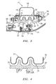
- FIG. 2 cross-sectional view in part of the embodiment of an active integrated clearance control system integrated within a high-pressure turbine of the gas turbine engine of FIG. 1;
- FIG. 3 is a representation of an enlarged area 3 of FIG. 2; and
- FIG. 4 is a representation of an enlarged area 4 of FIG. 3.
- Like reference numbers and designations in the various drawings indicate like elements.
- The exemplary active clearance control system described herein employs a single structure capable of being integrated into a gas turbine engine to supply, distribute and deliver working fluid while minimizing both weight and costs. The single structure also shields the engine components from harsh external environment of uneven temperatures and pressures. In addition, the single structure is spatially economical and can accommodate extra insulation and/or shielding if required. For purposes of explanation of the present invention, by "working fluid" means fluid supplied from the atmosphere and/or through one or more components of the gas turbine engine that enters the active clearance control system and possesses a temperature below the engine operating conditions or a temperature above the engine operating conditions.
- The active clearance control system described herein generally comprises an integrated manifold having a plenum defined by a manifold disposed opposite a shielding plate and having a divider plate disposed therebetween. The shielding plate includes a plurality of apertures to permit working fluid to enter the engine casing. The divider plate isolates the working fluid within the active clearance control system and uniformly distributes the air pressure. The integrated manifold includes one or more integral mounting devices for attachment to a turbine section of gas turbine engine. In the alternative, the integrated manifold includes a means for integrally mounting to the turbine section.
- Referring now to FIGS. 1 and 2, a representation of a
gas turbine engine 10 equipped with an activeclearance control system 14 of the present invention is shown. A representation of a cross-sectional view in part of the active clearance control system integrally mounted to aturbine 12 in thegas turbine engine 10 is shown in FIG. 2. Generally,gas turbine engine 10 includes a compressor, a combustor and a turbine. Theturbine 12 may consist of a single section or a low-pressure turbine section and a high-pressure turbine engine section. It is contemplated that the activeclearance control system 14 described herein may be used for either high-pressure or low-pressure applications. For example, the activeclearance control system 14 may be mounted to the high-pressure turbine section where the operating conditions, e.g., temperature and pressure, are most extreme. - Referring generally now to FIGS. 1 through 4, the active
clearance control system 14 generally comprises an integrated manifold comprising aplenum 16 defined by amanifold 18 disposed in connection with adivider plate 20 and disposed opposite ashielding plate 22 comprising a plurality ofapertures 24. Theapertures 24 permit working fluid to impinge thecase 26. The working fluid then circulates and exits into the atmosphere betweenshielding plate 22 andcase 26. The integrated manifold also includes a means for integrally mounting to acase 26 of the turbine. For example, one or moreintegral mounting devices 28 may be used to fixedly attach thesystem 14 to thecase 26. Suitable integral mounting devices may include, but are not limited to, brackets, screws, bolts, punches, rivets, welds, clips, and combinations thereof, and the like. - In employing the active clearance control system described herein, a quantity of working fluid may be introduced from the atmosphere, for example, ram air, or through the compressor stage of the
gas turbine engine 10 and into anaperture 13 of themanifold structure 18. The working fluid is not yet subjected to the extreme operating conditions present within thegas turbine engine 10 so the working fluid possesses a temperature lower than the operating temperature of theengine 10, thus providing a cooling effect. The working fluid travels through theplenum 16 and enters theturbine 12 through the plurality ofapertures 24 found throughout theshielding plate 22. The working fluid circulates through theapertures 24 andturbine 12 and eventually rises in temperature. - When the working fluid possesses a temperature lower than the engine's operating temperature, the working fluid makes contact with a plurality of
blade tips 30 of one or more rotor assemblies, along with other components, of thegas turbine engine 10, and cools theblade tips 30. Theblade tips 30 contract and the thermal growth experienced by the blades is reduced. As a result, the blade tip to shroud clearance, and/or anabradable material 34 concentrically disposed about theshroud 32, increases and eliminates transient clearance interference. - When the working fluid possesses a temperature greater than the engine's operating temperature, the working fluid makes contact with the
shroud 32, along with other components of thegas turbine engine 10, and warms theshroud 32. Theshroud 32 expands and the thermal growth experienced by theshroud 32 increases. As a result, blade tip to shroud clearance distance increases and eliminates transient clearance interference. - Throughout this process of increasing clearance distance and eliminating transient clearance interference, additional working fluid continues to be supplied to the active clearance control system of the present invention. For example, an electronic engine control system may schedule the working fluid intake into the active clearance control system.
- The active clearance control system may comprise any materials suitable for use in the operating environment of a gas turbine engine. Suitable materials may include, but are not limited to, a nickel based superalloy, a cobalt based superalloy, a ferrous alloy such as steel, a titanium alloy, a copper alloy, and combinations thereof.
- The active clearance control system of the present invention regulates the temperature and controls the thermal growth, that is, the expansion and/or contraction, of gas turbine engine components, such as blade and blade tips, shroud, case, and the like, and thereby control the blade tip to shroud clearance. The present active clearance control system may be switched or modulated responsive to various engine, aircraft, or environmental parameters for causing a reduction in blade tip to shroud clearance when such clearance control is most advantageous. In addition, the present active clearance control system is designed to utilize fewer parts so that the system itself does not exert inward radial forces upon the shroud and interfere with the blades.
- It is to be understood that the invention is not limited to the illustrations described and shown herein, which are deemed to be merely illustrative of the best modes of carrying out the invention, and which are susceptible to modification of form, size, arrangement of parts, and details of operation. The invention rather is intended to encompass all such modifications which are within its scope as defined by the claims.
Claims (13)
- A gas turbine engine (10), comprising:a compressor;a combustor; anda turbine (12),wherein said turbine (12) includes an integrated manifold comprising a plenum (16) defined by a manifold (18) disposed in connection with a divider plate (20) and opposite a shielding plate (22) comprising a plurality of apertures (24).
- The gas turbine engine (10) of claim 1, wherein said integrated manifold further comprises means for integrally mounting to said turbine (12).
- The gas turbine engine (10) of claim 1, wherein said integrated manifold further comprises an integral mounting device (28) selected from the group consisting of bracket, screw, bolt, punch, rivet, weld, clip, and combinations thereof.
- A gas turbine engine (10), comprising:a compressor;a combustor; anda turbine (12),wherein said turbine (10) includes an integrated manifold comprising a plenum (16) defined by a manifold (18) disposed in connection with a divider plate (20) and opposite a shielding plate (22) comprising a plurality of apertures (24) and means for integrally mounting to said turbine (12).
- A method for actively controlling clearances within a gas turbine engine (10), comprising the steps of:introducing a quantity of working fluid into an integrated manifold mounted to a turbine (12) of a gas turbine engine (10);circulating said working fluid throughout said integrated manifold and into said turbine (12); andincreasing a clearance distance between two components of said turbine (12).
- The method of claim 5, wherein increasing comprises increasing a clearance distance between a plurality of blade tips (30) of one or more rotor assemblies of said turbine (12) and a shroud (32) of said turbine (12).
- The method of claim 5, wherein increasing comprises increasing a clearance distance between a plurality of blade tips (30) of one or more rotor assemblies of said turbine (12) and an abradable material (34) concentrically disposed about a shroud (32) of said turbine (12).
- The method of claim 5, 6 or 7 wherein circulating comprises circulating said working fluid through a plenum (16) and one or more apertures (24) of a shielding plate (22) of said integrated manifold.
- The method of any of claims 5 to 8, wherein introducing comprises introducing a quantity of working fluid having a temperature less than an operating temperature of said gas turbine engine (10).
- The method of any of claims 5 to 8, wherein introducing comprises introducing a quantity of working fluid having a temperature greater than an operating temperature of said gas turbine engine (10).
- The method of any of claims 5 to 10, wherein introducing comprises introducing said quantity of working fluid from an atmosphere surrounding said gas turbine engine (10).
- The method of any of claims 5 to 10, wherein introducing comprises introducing said quantity of working fluid from within said gas turbine engine (10).
- The method of any of claims 5 to 12, wherein introducing comprises introducing said quantity of working fluid into an aperture (13) of said integrated manifold.
Applications Claiming Priority (1)
| Application Number | Priority Date | Filing Date | Title |
|---|---|---|---|
| US11/251,374 US7491029B2 (en) | 2005-10-14 | 2005-10-14 | Active clearance control system for gas turbine engines |
Publications (3)
| Publication Number | Publication Date |
|---|---|
| EP1775426A2 true EP1775426A2 (en) | 2007-04-18 |
| EP1775426A3 EP1775426A3 (en) | 2011-04-20 |
| EP1775426B1 EP1775426B1 (en) | 2016-05-04 |
Family
ID=37772551
Family Applications (1)
| Application Number | Title | Priority Date | Filing Date |
|---|---|---|---|
| EP06255254.2A Revoked EP1775426B1 (en) | 2005-10-14 | 2006-10-12 | Active clearance control system for gas turbine engines |
Country Status (6)
| Country | Link |
|---|---|
| US (1) | US7491029B2 (en) |
| EP (1) | EP1775426B1 (en) |
| JP (1) | JP2007107528A (en) |
| CN (1) | CN1948731A (en) |
| CA (1) | CA2563221A1 (en) |
| IL (1) | IL177801A0 (en) |
Cited By (4)
| Publication number | Priority date | Publication date | Assignee | Title |
|---|---|---|---|---|
| FR2907841A1 (en) * | 2006-10-30 | 2008-05-02 | Snecma Sa | Turbine ring sector for use in turbomachine i.e. aeronautical turbomachine, has multiperforated plate comprising bottom and side walls, where value of gap situated at upstream region is below value situated at downstream region |
| FR2943717A1 (en) * | 2009-03-27 | 2010-10-01 | Snecma | Stator for e.g. axial compressor of turbojet engine of airplane, has heating unit controlled by provoking radial dimensional variation of shroud, and coating and external heat insulation units insulating heating unit relative to air flow |
| EP2900941B1 (en) | 2012-09-26 | 2016-12-14 | United Technologies Corporation | Combined high pressure turbine case and turbine intermediate case |
| US9869196B2 (en) | 2014-06-24 | 2018-01-16 | General Electric Company | Gas turbine engine spring mounted manifold |
Families Citing this family (30)
| Publication number | Priority date | Publication date | Assignee | Title |
|---|---|---|---|---|
| US8434997B2 (en) * | 2007-08-22 | 2013-05-07 | United Technologies Corporation | Gas turbine engine case for clearance control |
| US20090053042A1 (en) * | 2007-08-22 | 2009-02-26 | General Electric Company | Method and apparatus for clearance control of turbine blade tip |
| US8061978B2 (en) * | 2007-10-16 | 2011-11-22 | United Technologies Corp. | Systems and methods involving abradable air seals |
| US8092146B2 (en) | 2009-03-26 | 2012-01-10 | Pratt & Whitney Canada Corp. | Active tip clearance control arrangement for gas turbine engine |
| JP5254112B2 (en) * | 2009-04-02 | 2013-08-07 | 株式会社東芝 | Gas turbine power generation equipment and clearance control system backup air supply method |
| GB2469490B (en) * | 2009-04-16 | 2012-03-07 | Rolls Royce Plc | Turbine casing cooling |
| GB201013723D0 (en) * | 2010-08-17 | 2010-09-29 | Rolls Royce Plc | Manifold mounting arrangement |
| US8714911B2 (en) * | 2011-01-06 | 2014-05-06 | General Electric Company | Impingement plate for turbomachine components and components equipped therewith |
| FR2977276B1 (en) * | 2011-06-30 | 2016-12-09 | Snecma | ARRANGEMENT FOR CONNECTING A DUCT TO AN AIR DISTRIBUTION HOUSING |
| US20130315716A1 (en) * | 2012-05-22 | 2013-11-28 | General Electric Company | Turbomachine having clearance control capability and system therefor |
| US8998563B2 (en) * | 2012-06-08 | 2015-04-07 | United Technologies Corporation | Active clearance control for gas turbine engine |
| WO2015102702A2 (en) * | 2013-10-07 | 2015-07-09 | United Technologies Corporation | Tailored thermal control system for gas turbine engine blade outer air seal array |
| US10443429B2 (en) * | 2014-02-13 | 2019-10-15 | United Technologies Corporation | Gas turbine nacelle ventilation manifold having a circumferential varying cross-sectional area |
| EP2977590B1 (en) * | 2014-07-25 | 2018-01-31 | Ansaldo Energia Switzerland AG | Compressor assembly for gas turbine |
| US9810091B2 (en) | 2014-08-12 | 2017-11-07 | United Technologies Corporation | Smart active clearance control between a rotor blade and a shroud |
| US10253644B2 (en) | 2014-11-26 | 2019-04-09 | United Technologies Corporation | Gas turbine engine clearance control |
| US10513944B2 (en) * | 2015-12-21 | 2019-12-24 | General Electric Company | Manifold for use in a clearance control system and method of manufacturing |
| US10087772B2 (en) | 2015-12-21 | 2018-10-02 | General Electric Company | Method and apparatus for active clearance control for high pressure compressors using fan/booster exhaust air |
| US10458429B2 (en) | 2016-05-26 | 2019-10-29 | Rolls-Royce Corporation | Impeller shroud with slidable coupling for clearance control in a centrifugal compressor |
| CN106382136B (en) * | 2016-11-18 | 2017-07-25 | 中国科学院工程热物理研究所 | An active control device for tip clearance of transonic moving blades |
| US10914185B2 (en) * | 2016-12-02 | 2021-02-09 | General Electric Company | Additive manufactured case with internal passages for active clearance control |
| US10415421B2 (en) | 2017-02-06 | 2019-09-17 | United Technologies Corporation | Thrust rating dependent active tip clearance control system |
| US10544803B2 (en) | 2017-04-17 | 2020-01-28 | General Electric Company | Method and system for cooling fluid distribution |
| US10941706B2 (en) | 2018-02-13 | 2021-03-09 | General Electric Company | Closed cycle heat engine for a gas turbine engine |
| US11143104B2 (en) | 2018-02-20 | 2021-10-12 | General Electric Company | Thermal management system |
| US11015534B2 (en) | 2018-11-28 | 2021-05-25 | General Electric Company | Thermal management system |
| US11788425B2 (en) * | 2021-11-05 | 2023-10-17 | General Electric Company | Gas turbine engine with clearance control system |
| CN116085067A (en) | 2021-11-05 | 2023-05-09 | 通用电气公司 | Gas turbine engine with fluid conduit system and method of operating the same |
| US12345163B2 (en) | 2023-11-17 | 2025-07-01 | Rolls-Royce Corporation | Travel stop for a tip clearance control system |
| US12345162B2 (en) | 2023-11-17 | 2025-07-01 | Rolls-Royce Corporation | Adjustable position impeller shroud for centrifugal compressors |
Citations (2)
| Publication number | Priority date | Publication date | Assignee | Title |
|---|---|---|---|---|
| GB2217788A (en) | 1988-03-31 | 1989-11-01 | Gen Electric | Gas turbine engine shroud clearance control |
| US20050042080A1 (en) | 2003-08-06 | 2005-02-24 | Snecma Moteurs | Device for controlling clearance in a gas turbine |
Family Cites Families (21)
| Publication number | Priority date | Publication date | Assignee | Title |
|---|---|---|---|---|
| US3825364A (en) | 1972-06-09 | 1974-07-23 | Gen Electric | Porous abradable turbine shroud |
| US3966354A (en) | 1974-12-19 | 1976-06-29 | General Electric Company | Thermal actuated valve for clearance control |
| US4230436A (en) | 1978-07-17 | 1980-10-28 | General Electric Company | Rotor/shroud clearance control system |
| FR2724973B1 (en) * | 1982-12-31 | 1996-12-13 | Snecma | DEVICE FOR SEALING MOBILE BLADES OF A TURBOMACHINE WITH REAL-TIME ACTIVE GAME CONTROL AND METHOD FOR DETERMINING SAID DEVICE |
| FR2540560B1 (en) * | 1983-02-03 | 1987-06-12 | Snecma | DEVICE FOR SEALING MOBILE BLADES OF A TURBOMACHINE |
| GB2195715B (en) | 1986-10-08 | 1990-10-10 | Rolls Royce Plc | Gas turbine engine rotor blade clearance control |
| US5012420A (en) | 1988-03-31 | 1991-04-30 | General Electric Company | Active clearance control for gas turbine engine |
| US5048288A (en) * | 1988-12-20 | 1991-09-17 | United Technologies Corporation | Combined turbine stator cooling and turbine tip clearance control |
| US5281085A (en) | 1990-12-21 | 1994-01-25 | General Electric Company | Clearance control system for separately expanding or contracting individual portions of an annular shroud |
| US5205115A (en) * | 1991-11-04 | 1993-04-27 | General Electric Company | Gas turbine engine case counterflow thermal control |
| US5205708A (en) | 1992-02-07 | 1993-04-27 | General Electric Company | High pressure turbine component interference fit up |
| US5399066A (en) * | 1993-09-30 | 1995-03-21 | General Electric Company | Integral clearance control impingement manifold and environmental shield |
| GB9709086D0 (en) | 1997-05-07 | 1997-06-25 | Rolls Royce Plc | Gas turbine engine cooling apparatus |
| FR2766231B1 (en) * | 1997-07-18 | 1999-08-20 | Snecma | CIRCULAR HOUSING HEATING OR COOLING DEVICE |
| FR2766517B1 (en) | 1997-07-24 | 1999-09-03 | Snecma | DEVICE FOR VENTILATION OF A TURBOMACHINE RING |
| DE10019437A1 (en) | 2000-04-19 | 2001-12-20 | Rolls Royce Deutschland | Method and device for cooling the housings of turbines of jet engines |
| US6454529B1 (en) | 2001-03-23 | 2002-09-24 | General Electric Company | Methods and apparatus for maintaining rotor assembly tip clearances |
| US6487491B1 (en) | 2001-11-21 | 2002-11-26 | United Technologies Corporation | System and method of controlling clearance between turbine engine blades and case based on engine components thermal growth model |
| US6659716B1 (en) * | 2002-07-15 | 2003-12-09 | Mitsubishi Heavy Industries, Ltd. | Gas turbine having thermally insulating rings |
| US7465145B2 (en) | 2005-03-17 | 2008-12-16 | United Technologies Corporation | Tip clearance control system |
| US8092146B2 (en) | 2009-03-26 | 2012-01-10 | Pratt & Whitney Canada Corp. | Active tip clearance control arrangement for gas turbine engine |
-
2005
- 2005-10-14 US US11/251,374 patent/US7491029B2/en not_active Expired - Lifetime
-
2006
- 2006-08-31 IL IL177801A patent/IL177801A0/en unknown
- 2006-10-12 CA CA002563221A patent/CA2563221A1/en not_active Abandoned
- 2006-10-12 EP EP06255254.2A patent/EP1775426B1/en not_active Revoked
- 2006-10-13 JP JP2006279353A patent/JP2007107528A/en active Pending
- 2006-10-16 CN CNA2006101359816A patent/CN1948731A/en active Pending
Patent Citations (2)
| Publication number | Priority date | Publication date | Assignee | Title |
|---|---|---|---|---|
| GB2217788A (en) | 1988-03-31 | 1989-11-01 | Gen Electric | Gas turbine engine shroud clearance control |
| US20050042080A1 (en) | 2003-08-06 | 2005-02-24 | Snecma Moteurs | Device for controlling clearance in a gas turbine |
Cited By (5)
| Publication number | Priority date | Publication date | Assignee | Title |
|---|---|---|---|---|
| FR2907841A1 (en) * | 2006-10-30 | 2008-05-02 | Snecma Sa | Turbine ring sector for use in turbomachine i.e. aeronautical turbomachine, has multiperforated plate comprising bottom and side walls, where value of gap situated at upstream region is below value situated at downstream region |
| US8348602B2 (en) | 2006-10-30 | 2013-01-08 | Snecma | Turbomachine turbine ring sector |
| FR2943717A1 (en) * | 2009-03-27 | 2010-10-01 | Snecma | Stator for e.g. axial compressor of turbojet engine of airplane, has heating unit controlled by provoking radial dimensional variation of shroud, and coating and external heat insulation units insulating heating unit relative to air flow |
| EP2900941B1 (en) | 2012-09-26 | 2016-12-14 | United Technologies Corporation | Combined high pressure turbine case and turbine intermediate case |
| US9869196B2 (en) | 2014-06-24 | 2018-01-16 | General Electric Company | Gas turbine engine spring mounted manifold |
Also Published As
| Publication number | Publication date |
|---|---|
| US7491029B2 (en) | 2009-02-17 |
| JP2007107528A (en) | 2007-04-26 |
| US20070086887A1 (en) | 2007-04-19 |
| IL177801A0 (en) | 2006-12-31 |
| EP1775426A3 (en) | 2011-04-20 |
| EP1775426B1 (en) | 2016-05-04 |
| CA2563221A1 (en) | 2007-04-14 |
| CN1948731A (en) | 2007-04-18 |
Similar Documents
| Publication | Publication Date | Title |
|---|---|---|
| US7491029B2 (en) | Active clearance control system for gas turbine engines | |
| EP1398474B1 (en) | Compressor bleed case | |
| EP2299061B1 (en) | Ceramic turbine shroud support | |
| US6142731A (en) | Low thermal expansion seal ring support | |
| US7094029B2 (en) | Methods and apparatus for controlling gas turbine engine rotor tip clearances | |
| US8784052B2 (en) | Ceramic gas turbine shroud | |
| EP1959103A2 (en) | Integrated support / thermocouple housing for impingement cooling manifolds and cooling method | |
| US5511940A (en) | Ceramic turbine nozzle | |
| EP2960441A1 (en) | Gas turbine engine spring mounted manifold | |
| EP1930549A2 (en) | Methods and systems for cooling integral turbine shroud assemblies | |
| EP2604926A1 (en) | System of integrating baffles for enhanced cooling of CMC liners | |
| US8137075B2 (en) | Compressor impellers, compressor sections including the compressor impellers, and methods of manufacturing | |
| EP3358144A1 (en) | Thrust rating dependent active tip clearance control system | |
| US10968764B2 (en) | Ceramic matrix composite hanger heat shield | |
| US10718450B2 (en) | Flange joint assembly for use in a gas turbine engine | |
| EP3091215A1 (en) | Attachment assembly and gas turbine engine with attachment assembly | |
| EP2956635B1 (en) | Heat shield manifold system for a midframe case of a gas turbine engine | |
| US20210062663A1 (en) | Airfoil assembly with ceramic matrix composite parts and load-transfer features | |
| EP1686242A2 (en) | Methods and apparatus for maintaining rotor assembly tip clearances | |
| EP2009250A2 (en) | Annular turbine casing of a gas turbine engine and corresponding turbine assembly | |
| US11970946B2 (en) | Clearance control assembly | |
| US11149560B2 (en) | Airfoil assembly with ceramic matrix composite parts and load-transfer features | |
| JP2008240730A (en) | Mounting system for impingement cooling manifold | |
| US20070110568A1 (en) | Pilot relief to reduce strut effects at pilot interface | |
| CN114278401A (en) | Turbine casing of turbine engine and turbine engine |
Legal Events
| Date | Code | Title | Description |
|---|---|---|---|
| PUAI | Public reference made under article 153(3) epc to a published international application that has entered the european phase |
Free format text: ORIGINAL CODE: 0009012 |
|
| AK | Designated contracting states |
Kind code of ref document: A2 Designated state(s): AT BE BG CH CY CZ DE DK EE ES FI FR GB GR HU IE IS IT LI LT LU LV MC NL PL PT RO SE SI SK TR |
|
| AX | Request for extension of the european patent |
Extension state: AL BA HR MK YU |
|
| PUAL | Search report despatched |
Free format text: ORIGINAL CODE: 0009013 |
|
| AK | Designated contracting states |
Kind code of ref document: A3 Designated state(s): AT BE BG CH CY CZ DE DK EE ES FI FR GB GR HU IE IS IT LI LT LU LV MC NL PL PT RO SE SI SK TR |
|
| AX | Request for extension of the european patent |
Extension state: AL BA HR MK RS |
|
| 17P | Request for examination filed |
Effective date: 20111020 |
|
| 17Q | First examination report despatched |
Effective date: 20111115 |
|
| AKX | Designation fees paid |
Designated state(s): DE GB |
|
| GRAP | Despatch of communication of intention to grant a patent |
Free format text: ORIGINAL CODE: EPIDOSNIGR1 |
|
| INTG | Intention to grant announced |
Effective date: 20160112 |
|
| GRAS | Grant fee paid |
Free format text: ORIGINAL CODE: EPIDOSNIGR3 |
|
| GRAA | (expected) grant |
Free format text: ORIGINAL CODE: 0009210 |
|
| AK | Designated contracting states |
Kind code of ref document: B1 Designated state(s): DE GB |
|
| REG | Reference to a national code |
Ref country code: GB Ref legal event code: FG4D |
|
| REG | Reference to a national code |
Ref country code: DE Ref legal event code: R081 Ref document number: 602006048945 Country of ref document: DE Owner name: UNITED TECHNOLOGIES CORP. (N.D.GES.D. STAATES , US Free format text: FORMER OWNER: UNITED TECHNOLOGIES CORP. (N.D.GES.D. STAATES DELAWARE), HARTFORD, CONN., US |
|
| REG | Reference to a national code |
Ref country code: DE Ref legal event code: R096 Ref document number: 602006048945 Country of ref document: DE |
|
| RAP2 | Party data changed (patent owner data changed or rights of a patent transferred) |
Owner name: UNITED TECHNOLOGIES CORPORATION |
|
| REG | Reference to a national code |
Ref country code: DE Ref legal event code: R026 Ref document number: 602006048945 Country of ref document: DE |
|
| PLBI | Opposition filed |
Free format text: ORIGINAL CODE: 0009260 |
|
| 26 | Opposition filed |
Opponent name: SAFRAN AIRCRAFT ENGINES Effective date: 20161226 |
|
| PLAX | Notice of opposition and request to file observation + time limit sent |
Free format text: ORIGINAL CODE: EPIDOSNOBS2 |
|
| REG | Reference to a national code |
Ref country code: DE Ref legal event code: R082 Ref document number: 602006048945 Country of ref document: DE Representative=s name: SCHMITT-NILSON SCHRAUD WAIBEL WOHLFROM PATENTA, DE |
|
| REG | Reference to a national code |
Ref country code: DE Ref legal event code: R082 Ref document number: 602006048945 Country of ref document: DE Representative=s name: SCHMITT-NILSON SCHRAUD WAIBEL WOHLFROM PATENTA, DE Ref country code: DE Ref legal event code: R081 Ref document number: 602006048945 Country of ref document: DE Owner name: UNITED TECHNOLOGIES CORP. (N.D.GES.D. STAATES , US Free format text: FORMER OWNER: UNITED TECHNOLOGIES CORPORATION, HARTFORD, CONN., US |
|
| PLBB | Reply of patent proprietor to notice(s) of opposition received |
Free format text: ORIGINAL CODE: EPIDOSNOBS3 |
|
| REG | Reference to a national code |
Ref country code: DE Ref legal event code: R064 Ref document number: 602006048945 Country of ref document: DE Ref country code: DE Ref legal event code: R103 Ref document number: 602006048945 Country of ref document: DE |
|
| PGFP | Annual fee paid to national office [announced via postgrant information from national office to epo] |
Ref country code: GB Payment date: 20180925 Year of fee payment: 13 |
|
| RDAF | Communication despatched that patent is revoked |
Free format text: ORIGINAL CODE: EPIDOSNREV1 |
|
| STAA | Information on the status of an ep patent application or granted ep patent |
Free format text: STATUS: THE PATENT HAS BEEN GRANTED |
|
| PGFP | Annual fee paid to national office [announced via postgrant information from national office to epo] |
Ref country code: DE Payment date: 20180819 Year of fee payment: 13 |
|
| RDAG | Patent revoked |
Free format text: ORIGINAL CODE: 0009271 |
|
| STAA | Information on the status of an ep patent application or granted ep patent |
Free format text: STATUS: PATENT REVOKED |
|
| 27W | Patent revoked |
Effective date: 20180925 |
|
| GBPR | Gb: patent revoked under art. 102 of the ep convention designating the uk as contracting state |
Effective date: 20180925 |