EP1775421A2 - Assembly for controlling thermal stresses in ceramic matrix composite articles - Google Patents
Assembly for controlling thermal stresses in ceramic matrix composite articles Download PDFInfo
- Publication number
- EP1775421A2 EP1775421A2 EP06255242A EP06255242A EP1775421A2 EP 1775421 A2 EP1775421 A2 EP 1775421A2 EP 06255242 A EP06255242 A EP 06255242A EP 06255242 A EP06255242 A EP 06255242A EP 1775421 A2 EP1775421 A2 EP 1775421A2
- Authority
- EP
- European Patent Office
- Prior art keywords
- assembly
- bodies
- platform
- vane
- ceramic
- Prior art date
- Legal status (The legal status is an assumption and is not a legal conclusion. Google has not performed a legal analysis and makes no representation as to the accuracy of the status listed.)
- Withdrawn
Links
Images

Classifications
-
- F—MECHANICAL ENGINEERING; LIGHTING; HEATING; WEAPONS; BLASTING
- F01—MACHINES OR ENGINES IN GENERAL; ENGINE PLANTS IN GENERAL; STEAM ENGINES
- F01D—NON-POSITIVE DISPLACEMENT MACHINES OR ENGINES, e.g. STEAM TURBINES
- F01D5/00—Blades; Blade-carrying members; Heating, heat-insulating, cooling or antivibration means on the blades or the members
- F01D5/12—Blades
- F01D5/28—Selecting particular materials; Particular measures relating thereto; Measures against erosion or corrosion
- F01D5/284—Selection of ceramic materials
-
- F—MECHANICAL ENGINEERING; LIGHTING; HEATING; WEAPONS; BLASTING
- F01—MACHINES OR ENGINES IN GENERAL; ENGINE PLANTS IN GENERAL; STEAM ENGINES
- F01D—NON-POSITIVE DISPLACEMENT MACHINES OR ENGINES, e.g. STEAM TURBINES
- F01D25/00—Component parts, details, or accessories, not provided for in, or of interest apart from, other groups
- F01D25/08—Cooling; Heating; Heat-insulation
- F01D25/12—Cooling
-
- F—MECHANICAL ENGINEERING; LIGHTING; HEATING; WEAPONS; BLASTING
- F05—INDEXING SCHEMES RELATING TO ENGINES OR PUMPS IN VARIOUS SUBCLASSES OF CLASSES F01-F04
- F05D—INDEXING SCHEME FOR ASPECTS RELATING TO NON-POSITIVE-DISPLACEMENT MACHINES OR ENGINES, GAS-TURBINES OR JET-PROPULSION PLANTS
- F05D2240/00—Components
- F05D2240/80—Platforms for stationary or moving blades
- F05D2240/81—Cooled platforms
-
- F—MECHANICAL ENGINEERING; LIGHTING; HEATING; WEAPONS; BLASTING
- F05—INDEXING SCHEMES RELATING TO ENGINES OR PUMPS IN VARIOUS SUBCLASSES OF CLASSES F01-F04
- F05D—INDEXING SCHEME FOR ASPECTS RELATING TO NON-POSITIVE-DISPLACEMENT MACHINES OR ENGINES, GAS-TURBINES OR JET-PROPULSION PLANTS
- F05D2260/00—Function
- F05D2260/20—Heat transfer, e.g. cooling
- F05D2260/221—Improvement of heat transfer
- F05D2260/2214—Improvement of heat transfer by increasing the heat transfer surface
- F05D2260/22141—Improvement of heat transfer by increasing the heat transfer surface using fins or ribs
-
- F—MECHANICAL ENGINEERING; LIGHTING; HEATING; WEAPONS; BLASTING
- F05—INDEXING SCHEMES RELATING TO ENGINES OR PUMPS IN VARIOUS SUBCLASSES OF CLASSES F01-F04
- F05D—INDEXING SCHEME FOR ASPECTS RELATING TO NON-POSITIVE-DISPLACEMENT MACHINES OR ENGINES, GAS-TURBINES OR JET-PROPULSION PLANTS
- F05D2260/00—Function
- F05D2260/94—Functionality given by mechanical stress related aspects such as low cycle fatigue [LCF] of high cycle fatigue [HCF]
- F05D2260/941—Functionality given by mechanical stress related aspects such as low cycle fatigue [LCF] of high cycle fatigue [HCF] particularly aimed at mechanical or thermal stress reduction
-
- F—MECHANICAL ENGINEERING; LIGHTING; HEATING; WEAPONS; BLASTING
- F05—INDEXING SCHEMES RELATING TO ENGINES OR PUMPS IN VARIOUS SUBCLASSES OF CLASSES F01-F04
- F05D—INDEXING SCHEME FOR ASPECTS RELATING TO NON-POSITIVE-DISPLACEMENT MACHINES OR ENGINES, GAS-TURBINES OR JET-PROPULSION PLANTS
- F05D2300/00—Materials; Properties thereof
- F05D2300/20—Oxide or non-oxide ceramics
- F05D2300/22—Non-oxide ceramics
- F05D2300/226—Carbides
-
- F—MECHANICAL ENGINEERING; LIGHTING; HEATING; WEAPONS; BLASTING
- F05—INDEXING SCHEMES RELATING TO ENGINES OR PUMPS IN VARIOUS SUBCLASSES OF CLASSES F01-F04
- F05D—INDEXING SCHEME FOR ASPECTS RELATING TO NON-POSITIVE-DISPLACEMENT MACHINES OR ENGINES, GAS-TURBINES OR JET-PROPULSION PLANTS
- F05D2300/00—Materials; Properties thereof
- F05D2300/60—Properties or characteristics given to material by treatment or manufacturing
- F05D2300/603—Composites; e.g. fibre-reinforced
Definitions
- This invention relates to ceramic matrix composite (CMC) articles, such as CMC components of gas turbine engines. More particularly, this invention is directed to an assembly and method for controlling thermally-induced stresses that exist within CMC articles when subjected to high temperatures while supported by metallic structures.
- CMC ceramic matrix composite
- Figures 1 and 2 represent a nozzle segment 10 that is one of a number of nozzle segments that when connected together form an annular-shaped high pressure turbine (HPT) nozzle assembly of a gas turbine engine.
- the segment 10 is made up of multiple vanes 12, each defining an airfoil and extending between outer and inner platforms (bands) 14 and 16.
- the vanes 12 and platforms 14 and 16 can be formed separately and then assembled, such as by brazing the ends of each vane 12 within openings defined in the platforms 14 and 16.
- the entire segment 10 can be formed as an integral casting.
- TBC thermal barrier coating
- the nozzle segment 10 expands and contracts when heated and cooled, respectively, during transient engine operating conditions.
- the placement of the vanes 12 directly in the hot gas path results in the vanes 12 sustaining temperatures that are significantly higher than that experienced by the platforms 14 and 16.
- the vanes 12 and platforms 14 and 16 are formed of similar materials, such as nickel-base superalloys widely used, the vanes 12 will expand and contract more than the platforms 14 and 16, thereby inducing significant thermally-induced strains and stresses in the segment 10.
- significant temperature gradients will exist along the length of each vane 12 as a result of direct heating by the combustion gases and the platforms 14 and 16 behaving as heat sinks, thereby further increasing the thermally-induced stresses within the vanes 12.
- CMC ceramic matrix composite
- SiC silicon carbide
- CMC vanes 12 In view of the higher operating temperatures sought for gas turbine engines to increase their efficiency, ceramic matrix composite (CMC) materials, such as silicon carbide (SiC)-containing CMC's, have been proposed as materials for certain components of gas turbine engines, including turbine vanes, blades, shrouds, combustor liners, and other high-temperature components of gas turbine engines.
- CMC materials have much higher temperature capabilities than the superalloys currently in use, and therefore better capable of withstanding the temperatures sustained in the hot gas path of a gas turbine engine.
- CMC vanes 12 also typically have relatively lower coefficients of thermal expansion (CTE), resulting in lower strains and stresses thermally induced by the higher temperatures sustained by the vanes 12 as compared to the platforms 14 and 16.
- CTE coefficients of thermal expansion
- CMC materials are also much less ductile and have significantly lower thermal conductivities than those of superalloys, rendering CMC vanes particularly prone to damage from thermally-induced stresses and strains.
- the general approach to implementing CMC vanes (e.g., 12) supported with superalloy platforms (e.g., 14 and 16) is to support the ends of the vanes with the platforms in a manner that allows differential thermal movement of the vanes relative to the platforms.
- Notable approaches are described in commonly-assigned U.S. Patent No. 5,630,700 to Olsen et al. and U.S. Patent No. 6,464,456 to Darolia et al.
- Various aspects of the present invention generally provide an assembly and method for controlling thermal stresses within a ceramic-based article when subjected to high temperatures while structurally supported by a metallic article.
- the assembly includes a first body formed of a metallic material and having oppositely-disposed first and second surfaces, and a second body formed of a ceramic-based material and supported by the first body from the first surface thereof.
- the first and second bodies are located in a hot gas path such that the second body and the first surface of the first body are directly impinged by flowing hot gases.
- the assembly further includes a substantially uniform pattern of fins protruding from the second surface of the first body.
- the fins are of sufficient size to increase the rigidity of the first body and promote heat transfer from the first body.
- the fins further serve to achieve more uniform temperatures within the first and second bodies and increase the stiffness of the first body to the extent that the thermal mass of the first body can be minimized.
- the assembly further has an interface structure between the first and second bodies.
- the interface structure comprises a resilient sealing member disposed between the first and second bodies and received in a recess in the first surface of the first body, and a ceramic saddle formed separately from the first and second bodies, received in the recess with the resilient sealing member, and disposed between the resilient sealing member and the second body.
- the ceramic saddle and resilient sealing member cooperate to assist in positively retaining the second body to the first body and thermally insulating the first body from the first body in a manner that reduces thermal stresses within the second body, such as those caused by thermal gradients within the second body.
- Various method embodiments of this invention generally entail forming a first body of a metallic material to have a first surface and a substantially uniform pattern of fins protruding from an oppositely-disposed second surface.
- the fins are of sufficient size to increase the rigidity of the first body and promote heat transfer from the first body.
- a second body of a ceramic-based material is then supported from the first surface of the first body.
- the resulting assembly is then placed in a hot gas path such that the second body and the first surface of the first body are directly impinged by flowing hot gases.
- FIGs 3 through 5 schematically represent a portion of a nozzle segment 20 that, when assembled with similarly configured segments, forms an annular-shaped HPT nozzle assembly of a gas turbine engine.
- the nozzle segment 20 is depicted as including a single vane 22 supported by a single platform 24, though it will be understood that multiple vanes can be supported by the platform 24 in combination with a second platform, resulting in a construction generally similar to that shown in Figures 1 and 2.
- the vane 22 is depicted as being hollow, though a variety of configurations are possible, including vanes configured to have struts, spars, inserts for mechanical support, baffles for enhanced internal cooling, etc. While the invention will be described in reference to a HPT nozzle assembly, it will be appreciated that the benefits of the invention can be applied to a variety of other components, including but not limited to low pressure turbine (LPT) nozzle assemblies and other hot section components of gas turbine engines.
- LPT low pressure turbine
- the platform 24 can be formed of such conventional materials as a single-crystal nickel, cobalt, or iron-base superalloy of a type suitable for use in gas turbine engines.
- Conventional practice has been to also form the vane 22 of the same or similar superalloy, such that the vane 22 and platform 24 would have similar CTE's and thermal conductivities to minimize thermally-induced strains and stresses during engine operation.
- the vane 22 is formed of a ceramic-based material, more preferably a CMC material such as a SiC/SiC (reinforcement/matrix) CMC.
- aspects of this invention are applicable to the use of a variety of ceramic-based and metallic materials, as well as intermetallic materials such as nickel aluminides (NiAl), and particularly combinations of these materials that result in combinations with significantly different CTE's and/or thermal conductivities.
- ceramic-based and metallic materials as well as intermetallic materials such as nickel aluminides (NiAl), and particularly combinations of these materials that result in combinations with significantly different CTE's and/or thermal conductivities.
- intermetallic materials such as nickel aluminides (NiAl)
- CMC materials of particular interest for the vane 22 may have CTE's and thermal conductivities in ranges of about 1.9 x10 -6 to about 2.3x10 -6 in/in ⁇ °F (about 8.7 x10 -5 to about 1.9 x10 -4 mm/mm ⁇ °C) and about 7.8 to about 19.6 BTU/hr ⁇ ft ⁇ °F (about 13.5 to about 33.9 W/mK), respectively, as compared to nickel-base superalloys whose CTE's and thermal conductivities of generally about 7.3 x10 -6 to about 8.5 x10 -6 in/in ⁇ °F (about 3.3 x10 -4 to about 3.9 x10 -4 mm/mm ⁇ °C) and about 6.8 to about 14.6 BTU/hr ⁇ ft ⁇ °F (about 11.8 to about 25.3 W/mK), respectively.
- Such differences in CTE's can cause considerable differential thermal movement between the vane 22 and platform 24, particularly during transient engine conditions when thermal conductivity and thermal mass also
- the vane 22 is seen as being supported from a surface 26 of the platform 24.
- the platform 24 would be oriented radially inward from the vane 22 within the engine, and therefore may be referred to as the inner platform (or band) of the nozzle segment 20.
- the vane 22 and surface 26 of the platform 24 are directly impinged by hot combustion gases discharged by the combustor (not shown) and flowing along the hot gas path of the engine. As such, the vane 22 and platform 24 are both subjected to intense heating during engine operation.
- a bleed air system may be employed that draws a portion of the compressed air from the engine's compressor (not shown) to cool the vane 22 and platform 24, such as through backside cooling of the platform 24 by directing bleed air at the inner surface 28 of the platform 24 opposite the vane 22, and/or by flowing bleed air through the vane 22, a portion of which may be optionally discharged through film cooling holes (not shown) on the surface of the vane 22.
- Such cooling techniques are well known in the art, and therefore do not require further explanation.
- the platform 24 is configured to include fins 30 protruding from its inner surface 28.
- the fins 30 are of a sufficient size to serve as stiffeners that increase the rigidity of the platform 24, thereby allowing the cross-sectional thickness of the platform 24 to be minimized to reduce the thermal mass of the platform 24.
- the fins 30 also preferably serve a secondary role of promoting radiation heat transfer from the platform 24 as a result of increased surface area from which heat can be radiated.
- Suitable dimensions for the fins 30 along the length of the platform 24 generally include a thickness (parallel to the surface 28) of about 2 to about 3 mm, and a height (normal to the surface 28) of about 2.5 to about 10 mm.
- the heights of the fins 30 increase immediately below the vane 22 to structurally accommodate a recess 38 (described in greater detail below) defined in the outer surface 26 of the platform 24.
- the fins 30 are preferably configured to define a substantially uniform pattern, such as the parallel pattern shown in Figure 3 through 5, with a suitable uniform spacing between fins 30 of about 6 to about 13 mm.
- the cross-sectional thickness of the platform 24 (excluding the fins 30) can be reduced by, for example, about 15 to about 25 percent while maintaining the same level of stiffness, and simultaneously resulting in a thermal mass reduction of about 10 to 20% or more for the platform 24.
- the fins 30 preferably extend the full circumferential length of the platform 24, and are integrally formed with the remainder of the platform 24 such as during a casting process of any type known and used to produce platforms for gas turbine engine nozzle assemblies. Alternatively, the fins 30 could be formed separately and attached by welding, brazing, etc.
- the vane 22 is shown in Figures 3 through 5 as mounted to the platform 24 with an interface structure 32 that provides a resilient, low thermal conductivity path between the vane 22 and platform 24.
- the interface structure 32 is represented as including a seal 34 and saddle 36, both of which are shown as being nested in the aforementioned recess 38 defined in the outer surface 26 of the platform 24.
- the recess 38 provides positive axial and tangential retention of the vane 22, the effect of which may be promoted by forming the recess 38 to extend through the inner surface 28 of the platform 24 and into the taller fins 30 shown immediately below the recess 38 in Figure 4.
- the seal 34 and saddle 36 are shown in Figure 4 as completely filling the recess 38 and continuous between the opposing surfaces of the vane 22 and platform 24.
- the seal 34 primarily provides the desired resilient interconnection between the vane 22 and platform 24, while also serving to inhibit gas leakage and heat transfer between the vane 22 and the platform 24.
- the seal 34 is preferably in the form of what may be termed a cloth seal, meaning a fabric-type sheet material woven from fibers.
- the fibers are preferably formed of an oxide dispersion strengthened (ODS) material, though the use of other high-temperature materials is foreseeable.
- ODS oxide dispersion strengthened
- the seal 34 is preferably at least 2 to 3 mm thick (normal to the surface 26) and a porosity of about 0.5 to about 1.0%.
- the seal 34 is preferably continuous beneath the vane 22, in contrast to the use of annular-shaped rope seals that surround the base of CMC vanes as proposed in the past.
- the seal 34 must also be sufficiently strong and stiff to resist compaction when under a compressive load between the vane 22 and platform 24.
- an example of a material suitable for use as the seal 34 is an ODS FeCrAl alloy commercially available from Plansee GmbH under the name PM2000.
- the saddle 36 is preferably formed of a ceramic-based material, more preferably a precast monolithic ceramic material such as SiC.
- a precast monolithic is believed to be preferred over a CMC material because of the desire for relatively precise control of the geometry of the saddle 36, such as small radii fillets joining the portions of the saddle 36 parallel to and normal to the surface 26 of the platform 24.
- the saddle 36 Without interfering with the resilient connection provided by the seal 34, the saddle 36 provides for positive retention of the vane 22 to the platform 24 by abutting a stepped shoulder 42 defined by the recess 38.
- the abutting-supporting arrangement between the edge of the saddle 36 and the shoulder 42, in combination with appropriate support at the end of the vane 22 opposite the platform 24, also inhibits compaction of the seal 34 by the saddle 36.
- the saddle 36 does not intentionally compress the seal 34.
- the ceramic material of the saddle 36 also provides additional thermal insulation within the interface structure 32 to inhibit heat transfer between the vane 22 and the platform 24.
- the portions of the saddle 36 parallel to and normal to the surface 26 of the platform 24 are each preferably at least 2.5 to 5 mm thick.
- the depth for the stepped shoulder 42 below the surface 26 of the platform 24 is preferably equal to the thickness of the portion of the saddle 36 within the recess 38 so that that portion of the saddle 36 is generally flush with the surface 26.
- the saddle 36, vane 22, and recess 38 in the surface 26 of the platform 24 are shown as having complementary configurations that form shiplap joints therebetween, as evident from Figure 4.
- both the seal 34 and saddle 36 is depicted as having L-shaped cross-sections that nest with each other and with a recess 40 defined in a wall of the vane 22, defining overlaps in both the plane parallel to the surface 26 and the plane normal to the surface 26.
- the presence of in-series shiplap joints serves to reduce gas leakage between the vane 22 and platform 24.
- the fins 30 serve to reduce the temperature of the platform 24 by promoting radiation heat transfer from the platform 24 and reducing the thermal mass of the platform 24.
- the interface structure 32 thermally insulates the vane 22 from the platform 24, thereby reducing thermal gradients within the vane 22 that could cause structural damage.
- the interface structure 32 further enables the vane 22 to be secured to the platform 24 in a manner that allows the vane 22 to expand and contract relative to the platform 24 during temperature excursions with reduced thermal-induced strains and stresses within the vane 22 that could cause the vane 22 to fracture during engine operation.
- the vane 22 is able to expand and contract both radially and laterally, the latter of which includes the circumferential and axial directions of the engine.
- the end of the vane 22 opposite the platform 24 can be secured with a second platform (corresponding to the outer platform 14 of Figure 1) in the same manner or optionally in a manner consistent with the prior art, including the use of more rigid attachment techniques.
- the interface structure 32 can potentially provide a sufficiently resilient connection between the vane 22 and its platform 24 to avoid the prior practice of constructing nozzle assemblies from multiple nozzle segments such as that shown in Figures 1 and 2, and instead forming the inner platform 24 (as well as the outer platform) as a single continuous ring.
Abstract
An assembly (20) and method for controlling thermal stresses within ceramic-based articles when subjected to high temperatures while supported by a metallic article. The assembly (20) includes a first body (24) formed of a metallic material and having oppositely-disposed first and second surfaces, and a second body (22) formed of a ceramic-based material and supported by the first body (24) from the first surface (26) thereof. The first and second bodies (24,22) are located in a hot gas path such that the second body (22) and the first surface (26) of the first body (24) are directly impinged by flowing hot gases. The assembly (20) further includes a substantially uniform pattern of fins (30) protruding from the second surface (28) of the first body (24), and/or an interface structure (32) between the first and second bodies (24,22) that positively retains the second body (22) to the first body (24) and thermally insulates the first body (24) from the first body (24).
Description
- This invention relates to ceramic matrix composite (CMC) articles, such as CMC components of gas turbine engines. More particularly, this invention is directed to an assembly and method for controlling thermally-induced stresses that exist within CMC articles when subjected to high temperatures while supported by metallic structures.
- Higher operating temperatures for gas turbine engines are continuously sought in order to increase their efficiency. However, as operating temperatures increase, the high temperature durability of the components of the engine must correspondingly increase. Significant advances in high temperature capabilities have been achieved through the formulation of iron, nickel and cobalt-base superalloys. Nonetheless, superalloy components must often be air-cooled and/or protected by some form of thermal and/or environmental coating system in order to exhibit suitable service lives in certain sections of a gas turbine engine, such as the turbine, combustor and augmentor.
- As an example, Figures 1 and 2 represent a
nozzle segment 10 that is one of a number of nozzle segments that when connected together form an annular-shaped high pressure turbine (HPT) nozzle assembly of a gas turbine engine. Thesegment 10 is made up ofmultiple vanes 12, each defining an airfoil and extending between outer and inner platforms (bands) 14 and 16. Thevanes 12 andplatforms vane 12 within openings defined in theplatforms entire segment 10 can be formed as an integral casting. As a result of being located in the high pressure turbine section of the engine, thevanes 12 and the surfaces of theplatforms vanes 12 are subjected to the hot combustion gases from the engine's combustor. Compressor bleed air is often supplied to thevanes 12 andplatforms vanes 12 andplatforms segment 10. - As one would expect, the
nozzle segment 10 expands and contracts when heated and cooled, respectively, during transient engine operating conditions. Though provided with thermal protection to minimize service temperatures, the placement of thevanes 12 directly in the hot gas path results in thevanes 12 sustaining temperatures that are significantly higher than that experienced by theplatforms vanes 12 andplatforms vanes 12 will expand and contract more than theplatforms segment 10. Furthermore, significant temperature gradients will exist along the length of eachvane 12 as a result of direct heating by the combustion gases and theplatforms vanes 12. - In view of the higher operating temperatures sought for gas turbine engines to increase their efficiency, ceramic matrix composite (CMC) materials, such as silicon carbide (SiC)-containing CMC's, have been proposed as materials for certain components of gas turbine engines, including turbine vanes, blades, shrouds, combustor liners, and other high-temperature components of gas turbine engines. CMC materials have much higher temperature capabilities than the superalloys currently in use, and therefore better capable of withstanding the temperatures sustained in the hot gas path of a gas turbine engine. Depending on the exact materials used,
CMC vanes 12 also typically have relatively lower coefficients of thermal expansion (CTE), resulting in lower strains and stresses thermally induced by the higher temperatures sustained by thevanes 12 as compared to theplatforms U.S. Patent No. 5,630,700 to Olsen et al. andU.S. Patent No. 6,464,456 to Darolia et al. - Notwithstanding the above advancements proposed by Olsen et al. and Darolia et al., further improvements would be desirable in order to fully implement nozzle assemblies having CMC vanes supported by metallic platforms. In particular, it would be desirable to improve the interface and attachment of the CMC vanes to the metallic platforms in order to not only reduce temperatures and thermally-induced stresses and strains, but also minimize the significant temperature gradients that can exist within a
CMC vane 12, which have been observed at times to exceed about 600°F per inch (about 124°C/cm). - Various aspects of the present invention generally provide an assembly and method for controlling thermal stresses within a ceramic-based article when subjected to high temperatures while structurally supported by a metallic article.
- The assembly includes a first body formed of a metallic material and having oppositely-disposed first and second surfaces, and a second body formed of a ceramic-based material and supported by the first body from the first surface thereof. The first and second bodies are located in a hot gas path such that the second body and the first surface of the first body are directly impinged by flowing hot gases. According to a first aspect of the invention, the assembly further includes a substantially uniform pattern of fins protruding from the second surface of the first body. The fins are of sufficient size to increase the rigidity of the first body and promote heat transfer from the first body. According to a preferred aspect of the invention, the fins further serve to achieve more uniform temperatures within the first and second bodies and increase the stiffness of the first body to the extent that the thermal mass of the first body can be minimized.
- According to a second aspect of the invention, the assembly further has an interface structure between the first and second bodies. The interface structure comprises a resilient sealing member disposed between the first and second bodies and received in a recess in the first surface of the first body, and a ceramic saddle formed separately from the first and second bodies, received in the recess with the resilient sealing member, and disposed between the resilient sealing member and the second body. According to this aspect of the invention, the ceramic saddle and resilient sealing member cooperate to assist in positively retaining the second body to the first body and thermally insulating the first body from the first body in a manner that reduces thermal stresses within the second body, such as those caused by thermal gradients within the second body.
- Various method embodiments of this invention generally entail forming a first body of a metallic material to have a first surface and a substantially uniform pattern of fins protruding from an oppositely-disposed second surface. The fins are of sufficient size to increase the rigidity of the first body and promote heat transfer from the first body. A second body of a ceramic-based material is then supported from the first surface of the first body. The resulting assembly is then placed in a hot gas path such that the second body and the first surface of the first body are directly impinged by flowing hot gases.
- It can be appreciated from the above that the various aspects of invention are particularly applicable to nozzle assemblies of gas turbine engines, specifically where a ceramic-based vane is supported by and between a pair of platforms.
- Other objects and advantages of this invention will be better appreciated from the following detailed description, and Figures, in which:
- Figures 1 and 2 are perspective and cross-sectional views, respectively, of a nozzle segment for a gas turbine engine and of a type that can benefit from aspects of the present invention.
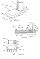
- Figure 3 is a perspective view showing a portion of a nozzle assembly configured in accordance with a preferred embodiment of the present invention.
- Figure 4 is a cross-sectional view of the nozzle assembly of Figure 3 taken along section line 4-4 in Figure 3.
- Figure 5 is a sectional view of the nozzle assembly of Figure 3 taken along section line 5-5 in Figure 4.
- Figures 3 through 5 schematically represent a portion of a
nozzle segment 20 that, when assembled with similarly configured segments, forms an annular-shaped HPT nozzle assembly of a gas turbine engine. Thenozzle segment 20 is depicted as including asingle vane 22 supported by asingle platform 24, though it will be understood that multiple vanes can be supported by theplatform 24 in combination with a second platform, resulting in a construction generally similar to that shown in Figures 1 and 2. Thevane 22 is depicted as being hollow, though a variety of configurations are possible, including vanes configured to have struts, spars, inserts for mechanical support, baffles for enhanced internal cooling, etc. While the invention will be described in reference to a HPT nozzle assembly, it will be appreciated that the benefits of the invention can be applied to a variety of other components, including but not limited to low pressure turbine (LPT) nozzle assemblies and other hot section components of gas turbine engines. - The
platform 24 can be formed of such conventional materials as a single-crystal nickel, cobalt, or iron-base superalloy of a type suitable for use in gas turbine engines. Conventional practice has been to also form thevane 22 of the same or similar superalloy, such that thevane 22 andplatform 24 would have similar CTE's and thermal conductivities to minimize thermally-induced strains and stresses during engine operation. However, according to embodiments of the invention thevane 22 is formed of a ceramic-based material, more preferably a CMC material such as a SiC/SiC (reinforcement/matrix) CMC. However, it should be understood that aspects of this invention are applicable to the use of a variety of ceramic-based and metallic materials, as well as intermetallic materials such as nickel aluminides (NiAl), and particularly combinations of these materials that result in combinations with significantly different CTE's and/or thermal conductivities. For example, CMC materials of particular interest for thevane 22 may have CTE's and thermal conductivities in ranges of about 1.9 x10⁻⁶ to about 2.3x10⁻⁶ in/in·°F (about 8.7 x10⁻⁵ to about 1.9 x10⁻⁴ mm/mm·°C) and about 7.8 to about 19.6 BTU/hr·ft·°F (about 13.5 to about 33.9 W/mK), respectively, as compared to nickel-base superalloys whose CTE's and thermal conductivities of generally about 7.3 x10⁻⁶ to about 8.5 x10⁻⁶ in/in ·°F (about 3.3 x10⁻⁴ to about 3.9 x10⁻⁴ mm/mm·°C) and about 6.8 to about 14.6 BTU/hr·ft·°F (about 11.8 to about 25.3 W/mK), respectively. Such differences in CTE's can cause considerable differential thermal movement between thevane 22 andplatform 24, particularly during transient engine conditions when thermal conductivity and thermal mass also come into play. - From Figures 3 through 5, the
vane 22 is seen as being supported from asurface 26 of theplatform 24. In the particular embodiment shown in Figures 3 through 5, theplatform 24 would be oriented radially inward from thevane 22 within the engine, and therefore may be referred to as the inner platform (or band) of thenozzle segment 20. When installed on a gas turbine engine, thevane 22 andsurface 26 of theplatform 24 are directly impinged by hot combustion gases discharged by the combustor (not shown) and flowing along the hot gas path of the engine. As such, thevane 22 andplatform 24 are both subjected to intense heating during engine operation. Consequently, a bleed air system may be employed that draws a portion of the compressed air from the engine's compressor (not shown) to cool thevane 22 andplatform 24, such as through backside cooling of theplatform 24 by directing bleed air at theinner surface 28 of theplatform 24 opposite thevane 22, and/or by flowing bleed air through thevane 22, a portion of which may be optionally discharged through film cooling holes (not shown) on the surface of thevane 22. Such cooling techniques are well known in the art, and therefore do not require further explanation. - As evident from Figures 3 through 5, the
platform 24 is configured to includefins 30 protruding from itsinner surface 28. Thefins 30 are of a sufficient size to serve as stiffeners that increase the rigidity of theplatform 24, thereby allowing the cross-sectional thickness of theplatform 24 to be minimized to reduce the thermal mass of theplatform 24. As a result, the thermal inertia of theplatform 24 is reduced, promoting more rapid heat transfer from theplatform 24 with backside cooling. Thefins 30 also preferably serve a secondary role of promoting radiation heat transfer from theplatform 24 as a result of increased surface area from which heat can be radiated. Suitable dimensions for thefins 30 along the length of theplatform 24 generally include a thickness (parallel to the surface 28) of about 2 to about 3 mm, and a height (normal to the surface 28) of about 2.5 to about 10 mm. In the embodiment depicted in Figures 3 through 5, the heights of thefins 30 increase immediately below thevane 22 to structurally accommodate a recess 38 (described in greater detail below) defined in theouter surface 26 of theplatform 24. To promote a more uniform temperature within theplatform 24, thefins 30 are preferably configured to define a substantially uniform pattern, such as the parallel pattern shown in Figure 3 through 5, with a suitable uniform spacing betweenfins 30 of about 6 to about 13 mm. Because of the increased stiffness contributed by thefins 30 to theplatform 24, the cross-sectional thickness of the platform 24 (excluding the fins 30) can be reduced by, for example, about 15 to about 25 percent while maintaining the same level of stiffness, and simultaneously resulting in a thermal mass reduction of about 10 to 20% or more for theplatform 24. Thefins 30 preferably extend the full circumferential length of theplatform 24, and are integrally formed with the remainder of theplatform 24 such as during a casting process of any type known and used to produce platforms for gas turbine engine nozzle assemblies. Alternatively, thefins 30 could be formed separately and attached by welding, brazing, etc. - The
vane 22 is shown in Figures 3 through 5 as mounted to theplatform 24 with aninterface structure 32 that provides a resilient, low thermal conductivity path between thevane 22 andplatform 24. Theinterface structure 32 is represented as including aseal 34 andsaddle 36, both of which are shown as being nested in theaforementioned recess 38 defined in theouter surface 26 of theplatform 24. Therecess 38 provides positive axial and tangential retention of thevane 22, the effect of which may be promoted by forming therecess 38 to extend through theinner surface 28 of theplatform 24 and into thetaller fins 30 shown immediately below therecess 38 in Figure 4. Together theseal 34 andsaddle 36 are shown in Figure 4 as completely filling therecess 38 and continuous between the opposing surfaces of thevane 22 andplatform 24. - The
seal 34 primarily provides the desired resilient interconnection between thevane 22 andplatform 24, while also serving to inhibit gas leakage and heat transfer between thevane 22 and theplatform 24. Theseal 34 is preferably in the form of what may be termed a cloth seal, meaning a fabric-type sheet material woven from fibers. To withstand the high temperatures of the combustion gases within a high pressure turbine, the fibers are preferably formed of an oxide dispersion strengthened (ODS) material, though the use of other high-temperature materials is foreseeable. To have sufficient resilience and provide a desired level of thermal insulation, theseal 34 is preferably at least 2 to 3 mm thick (normal to the surface 26) and a porosity of about 0.5 to about 1.0%. Furthermore, theseal 34 is preferably continuous beneath thevane 22, in contrast to the use of annular-shaped rope seals that surround the base of CMC vanes as proposed in the past. Theseal 34 must also be sufficiently strong and stiff to resist compaction when under a compressive load between thevane 22 andplatform 24. In view of the above considerations, an example of a material suitable for use as theseal 34 is an ODS FeCrAl alloy commercially available from Plansee GmbH under the name PM2000. - The
saddle 36 is preferably formed of a ceramic-based material, more preferably a precast monolithic ceramic material such as SiC. A precast monolithic is believed to be preferred over a CMC material because of the desire for relatively precise control of the geometry of thesaddle 36, such as small radii fillets joining the portions of thesaddle 36 parallel to and normal to thesurface 26 of theplatform 24. Without interfering with the resilient connection provided by theseal 34, thesaddle 36 provides for positive retention of thevane 22 to theplatform 24 by abutting a steppedshoulder 42 defined by therecess 38. The abutting-supporting arrangement between the edge of thesaddle 36 and theshoulder 42, in combination with appropriate support at the end of thevane 22 opposite theplatform 24, also inhibits compaction of theseal 34 by thesaddle 36. In the preferred embodiment, thesaddle 36 does not intentionally compress theseal 34. The ceramic material of thesaddle 36 also provides additional thermal insulation within theinterface structure 32 to inhibit heat transfer between thevane 22 and theplatform 24. To have sufficient thickness for structural strength, the portions of thesaddle 36 parallel to and normal to thesurface 26 of theplatform 24 are each preferably at least 2.5 to 5 mm thick. The depth for the steppedshoulder 42 below thesurface 26 of theplatform 24 is preferably equal to the thickness of the portion of thesaddle 36 within therecess 38 so that that portion of thesaddle 36 is generally flush with thesurface 26. - The
saddle 36,vane 22, andrecess 38 in thesurface 26 of theplatform 24 are shown as having complementary configurations that form shiplap joints therebetween, as evident from Figure 4. In particular, both theseal 34 andsaddle 36 is depicted as having L-shaped cross-sections that nest with each other and with arecess 40 defined in a wall of thevane 22, defining overlaps in both the plane parallel to thesurface 26 and the plane normal to thesurface 26. The presence of in-series shiplap joints serves to reduce gas leakage between thevane 22 andplatform 24. - As noted above, the
fins 30 serve to reduce the temperature of theplatform 24 by promoting radiation heat transfer from theplatform 24 and reducing the thermal mass of theplatform 24. With the combination of theseal 34 andsaddle 36 represented in Figures 3 through 5, theinterface structure 32 thermally insulates thevane 22 from theplatform 24, thereby reducing thermal gradients within thevane 22 that could cause structural damage. Theinterface structure 32 further enables thevane 22 to be secured to theplatform 24 in a manner that allows thevane 22 to expand and contract relative to theplatform 24 during temperature excursions with reduced thermal-induced strains and stresses within thevane 22 that could cause thevane 22 to fracture during engine operation. More particularly, thevane 22 is able to expand and contract both radially and laterally, the latter of which includes the circumferential and axial directions of the engine. The end of thevane 22 opposite theplatform 24 can be secured with a second platform (corresponding to theouter platform 14 of Figure 1) in the same manner or optionally in a manner consistent with the prior art, including the use of more rigid attachment techniques. With either approach, theinterface structure 32 can potentially provide a sufficiently resilient connection between thevane 22 and itsplatform 24 to avoid the prior practice of constructing nozzle assemblies from multiple nozzle segments such as that shown in Figures 1 and 2, and instead forming the inner platform 24 (as well as the outer platform) as a single continuous ring. - While the invention has been described in terms of a particular embodiment, it is apparent that other forms could be adopted by one skilled in the art. For example, the
vane 22,platform 24,fins 30, andinterface structure 32 could be configured differently from that shown in the Figures while still achieving one or more of the intended objects of the invention. Accordingly, the scope of the invention is to be limited only by the following claims. -
- 10
- Segment
- 12
- Vanes
- 14
- Platforms
- 16
- Platfonns
- 20
- Segment
- 22
- Vane
- 24
- Platform
- 26
- Surface
- 28
- Surface
- 30
- Fins
- 32
- Structure
- 34
- Seal
- 36
- Saddle
- 38
- Recess
- 40
- Recess
- 42
- Shoulder
Claims (10)
- An assembly (20) comprising a first body (24) formed of a metallic material and having a first surface (26) and an oppositely-disposed second surface (28), and a second body (22) formed of a ceramic-based material and supported by the first body (24) from the first surface (26) thereof, the first and second bodies (24,22) being located in a hot gas path such that the second body (22) and the first surface (26) of the first body (24) are directly impinged by flowing hot gases, characterized in that:a substantially uniform pattern of fins (30) protrudes from the second surface (28) of the first body (24), the fins (30) being of sufficient size to increase the rigidity of the first body (24) and promote heat transfer from the first body (24).
- An assembly (20) according to claim 1, characterized in that the fins (30) are integrally formed with the first body (24).
- An assembly (20) according to claim 1 or claim 2, characterized in that the first body (24) has a recess (38) in the first surface (26) thereof, the assembly (20) further comprising an interface structure (32) between the first and second bodies (24,22), the interface structure (32) comprising a resilient sealing member (34) received in the recess (38) and disposed between the first and second bodies (24,22), the interface structure (32) further comprising a ceramic saddle (36) formed separately from the first and second bodies (24,22), received in the recess (38) with the resilient sealing member (34), and disposed between the resilient sealing member (34) and the second body (22).
- An assembly (20) comprising first and second bodies (24,22), the first body (24) being formed of a metallic material and having a first surface (26), an oppositely-disposed second surface (28), and a recess (38) in the first surface (26), the second body (22) being formed of a ceramic-based material and supported by the first body (24) from the first surface (26) thereof, the first and second bodies (24,22) being located in a hot gas path such that the second body (22) and the first surface (26) of the first body (24) are directly impinged by flowing hot gases, characterized in that:an interface structure (32) is disposed between the first and second bodies (24,22), the interface structure (32) comprising a resilient sealing member (34) received in the recess (38) and disposed between the first and second bodies (24,22), the interface structure (32) further comprising a ceramic saddle (36) formed separately from the first and second bodies (24,22), received in the recess (38) with the resilient sealing member (34), and disposed between the resilient sealing member (34) and the second body (22).
- An assembly (20) according to claims 3 or 4, characterized in that the ceramic saddle (36) and the resilient sealing member (34) define a shiplap joint therebetween.
- An assembly (20) according to any one of claims 3 through 5, characterized in that the resilient sealing member (34) comprises a fabric sheet material that is continuous between the vane (22) and the platform (24).
- An assembly (20) according to any one of claims 3 through 6, characterized in that the ceramic saddle (36) is formed of a monolithic ceramic material.
- An assembly (20) according to any one of claims 1 through 7, characterized in that cooling air impinges the second surface (28) of the first body (24).
- An assembly (20) according to any one of claims 1 through 8, characterized in that the assembly (20) is a nozzle segment (20) of a gas turbine engine, the first body (24) is a platform (24) of the nozzle segment (20), and the second body (22) is a vane (22) of the nozzle segment (20).
- An assembly (20) according to any one of claims 1 through 9, further comprising a third body that supports the second body (22) opposite the first body (24) such that the second body (22) is between the first and third bodies (24).
Applications Claiming Priority (1)
| Application Number | Priority Date | Filing Date | Title |
|---|---|---|---|
| US11/163,320 US20070122266A1 (en) | 2005-10-14 | 2005-10-14 | Assembly for controlling thermal stresses in ceramic matrix composite articles |
Publications (1)
| Publication Number | Publication Date |
|---|---|
| EP1775421A2 true EP1775421A2 (en) | 2007-04-18 |
Family
ID=37735264
Family Applications (1)
| Application Number | Title | Priority Date | Filing Date |
|---|---|---|---|
| EP06255242A Withdrawn EP1775421A2 (en) | 2005-10-14 | 2006-10-12 | Assembly for controlling thermal stresses in ceramic matrix composite articles |
Country Status (4)
| Country | Link |
|---|---|
| US (1) | US20070122266A1 (en) |
| EP (1) | EP1775421A2 (en) |
| JP (1) | JP2007107524A (en) |
| CN (1) | CN1948719A (en) |
Cited By (2)
| Publication number | Priority date | Publication date | Assignee | Title |
|---|---|---|---|---|
| FR2978495A1 (en) * | 2011-07-25 | 2013-02-01 | Snecma | Annular casing i.e. intermediate casing, for multi-stream turbojet engine of aircraft, has ring sector made of composite material, and another ring sector made of metal, where arms of ring sectors connect one element to another element |
| WO2014158276A3 (en) * | 2013-03-05 | 2014-12-04 | Rolls-Royce Corporation | Structure and method for providing compliance and sealing between ceramic and metallic structures |
Families Citing this family (25)
| Publication number | Priority date | Publication date | Assignee | Title |
|---|---|---|---|---|
| DE102006057912A1 (en) * | 2006-12-08 | 2008-06-12 | Mtu Aero Engines Gmbh | Vane ring and method for producing the same |
| US20090067978A1 (en) * | 2007-05-24 | 2009-03-12 | Suljak Jr George T | Variable area turbine vane arrangement |
| US8240987B2 (en) * | 2008-08-15 | 2012-08-14 | United Technologies Corp. | Gas turbine engine systems involving baffle assemblies |
| US8322983B2 (en) * | 2008-09-11 | 2012-12-04 | Siemens Energy, Inc. | Ceramic matrix composite structure |
| EP2186581B1 (en) * | 2008-11-14 | 2013-07-24 | Alstom Technology Ltd | Multi vane segment design and casting method |
| CH700001A1 (en) * | 2008-11-20 | 2010-05-31 | Alstom Technology Ltd | Moving blade arrangement, especially for a gas turbine. |
| CN101581718B (en) * | 2009-06-26 | 2012-07-25 | 陕西科技大学 | Method for on-line soft measurement of internal stress of ceramic paste |
| US9228445B2 (en) | 2010-12-23 | 2016-01-05 | General Electric Company | Turbine airfoil components containing ceramic-based materials and processes therefor |
| US8721290B2 (en) * | 2010-12-23 | 2014-05-13 | General Electric Company | Processes for producing components containing ceramic-based and metallic materials |
| US8777582B2 (en) | 2010-12-27 | 2014-07-15 | General Electric Company | Components containing ceramic-based materials and coatings therefor |
| US8777583B2 (en) | 2010-12-27 | 2014-07-15 | General Electric Company | Turbine airfoil components containing ceramic-based materials and processes therefor |
| FR2974593B1 (en) * | 2011-04-28 | 2015-11-13 | Snecma | TURBINE ENGINE COMPRISING A METAL PROTECTION OF A COMPOSITE PIECE |
| US8770931B2 (en) * | 2011-05-26 | 2014-07-08 | United Technologies Corporation | Hybrid Ceramic Matrix Composite vane structures for a gas turbine engine |
| US8905711B2 (en) | 2011-05-26 | 2014-12-09 | United Technologies Corporation | Ceramic matrix composite vane structures for a gas turbine engine turbine |
| US9039364B2 (en) * | 2011-06-29 | 2015-05-26 | United Technologies Corporation | Integrated case and stator |
| WO2014197105A2 (en) | 2013-03-25 | 2014-12-11 | United Technologies Corporation | Non-integral blade and platform segment for rotor |
| US9040138B2 (en) * | 2013-04-29 | 2015-05-26 | General Electric Company | Composite article including composite to metal interlock and method of fabrication |
| US10287899B2 (en) * | 2013-10-21 | 2019-05-14 | United Technologies Corporation | Ceramic attachment configuration and method for manufacturing same |
| EP3023696B1 (en) * | 2014-11-20 | 2019-08-28 | Ansaldo Energia Switzerland AG | Lobe lance for a gas turbine combustor |
| US20170059165A1 (en) | 2015-08-28 | 2017-03-02 | Rolls-Royce High Temperature Composites Inc. | Cmc cross-over tube |
| US10544793B2 (en) * | 2017-01-25 | 2020-01-28 | General Electric Company | Thermal isolation structure for rotating turbine frame |
| US10697313B2 (en) | 2017-02-01 | 2020-06-30 | General Electric Company | Turbine engine component with an insert |
| US20180363488A1 (en) * | 2017-06-14 | 2018-12-20 | Rolls-Royce Corporation | Tip clearance control with finned case design |
| US10808553B2 (en) * | 2018-11-13 | 2020-10-20 | Rolls-Royce Plc | Inter-component seals for ceramic matrix composite turbine vane assemblies |
| US11428160B2 (en) | 2020-12-31 | 2022-08-30 | General Electric Company | Gas turbine engine with interdigitated turbine and gear assembly |
Family Cites Families (6)
| Publication number | Priority date | Publication date | Assignee | Title |
|---|---|---|---|---|
| EP0637476B1 (en) * | 1993-08-06 | 2000-02-23 | Hitachi, Ltd. | Blade for gas turbine, manufacturing method of the same, and gas turbine including the blade |
| US5634766A (en) * | 1994-08-23 | 1997-06-03 | General Electric Co. | Turbine stator vane segments having combined air and steam cooling circuits |
| US5630700A (en) * | 1996-04-26 | 1997-05-20 | General Electric Company | Floating vane turbine nozzle |
| US6200092B1 (en) * | 1999-09-24 | 2001-03-13 | General Electric Company | Ceramic turbine nozzle |
| US6464456B2 (en) * | 2001-03-07 | 2002-10-15 | General Electric Company | Turbine vane assembly including a low ductility vane |
| JP4508482B2 (en) * | 2001-07-11 | 2010-07-21 | 三菱重工業株式会社 | Gas turbine stationary blade |
-
2005
- 2005-10-14 US US11/163,320 patent/US20070122266A1/en not_active Abandoned
-
2006
- 2006-10-11 JP JP2006277217A patent/JP2007107524A/en not_active Withdrawn
- 2006-10-12 EP EP06255242A patent/EP1775421A2/en not_active Withdrawn
- 2006-10-13 CN CNA2006101359248A patent/CN1948719A/en active Pending
Cited By (3)
| Publication number | Priority date | Publication date | Assignee | Title |
|---|---|---|---|---|
| FR2978495A1 (en) * | 2011-07-25 | 2013-02-01 | Snecma | Annular casing i.e. intermediate casing, for multi-stream turbojet engine of aircraft, has ring sector made of composite material, and another ring sector made of metal, where arms of ring sectors connect one element to another element |
| WO2014158276A3 (en) * | 2013-03-05 | 2014-12-04 | Rolls-Royce Corporation | Structure and method for providing compliance and sealing between ceramic and metallic structures |
| US9951640B2 (en) | 2013-03-05 | 2018-04-24 | Rolls-Royce Corporation | Structure and method for providing compliance and sealing between ceramic and metallic structures |
Also Published As
| Publication number | Publication date |
|---|---|
| CN1948719A (en) | 2007-04-18 |
| US20070122266A1 (en) | 2007-05-31 |
| JP2007107524A (en) | 2007-04-26 |
Similar Documents
| Publication | Publication Date | Title |
|---|---|---|
| EP1775421A2 (en) | Assembly for controlling thermal stresses in ceramic matrix composite articles | |
| EP3091187B1 (en) | Turbine component assembly with thermally stress-free fastener | |
| EP3054218B1 (en) | Combustion chamber | |
| US10329950B2 (en) | Nozzle guide vane with composite heat shield | |
| EP3155231B1 (en) | Shroud hanger assembly | |
| EP2549188B1 (en) | Insert for a gas turbine engine combustor | |
| EP1347151B1 (en) | Hybrid high temperature article for gas turbines and method of making the same | |
| US7452182B2 (en) | Multi-piece turbine vane assembly | |
| EP2051009B1 (en) | Ceramic combustor liner panel for a gas turbine engine | |
| US20140212284A1 (en) | Hybrid turbine nozzle | |
| US8734107B2 (en) | Ceramic-based tip cap for a turbine bucket | |
| US11466855B2 (en) | Gas turbine engine combustor with ceramic matrix composite liner | |
| US10975709B1 (en) | Turbine vane assembly with ceramic matrix composite components and sliding support | |
| US9174275B2 (en) | Method for manufacturing a metal-ceramic composite structure and metal-ceramic composite structure | |
| EP2538137B1 (en) | Combustor with strain tolerant combustor panel for gas turbine engine | |
| EP2578807A2 (en) | Airfoil for turbine system | |
| WO2020018090A1 (en) | Hybrid components having an intermediate ceramic fiber material | |
| EP3372790A1 (en) | Component having a hybrid coating system and method for forming a component | |
| US10436041B2 (en) | Shroud assembly for turbine systems | |
| WO2017039607A1 (en) | Turbine vane insert | |
| WO2019046022A1 (en) | Hybrid cmc component having integral and modular shrouds | |
| WO2021021206A1 (en) | Method of securing a ceramic matrix composite (cmc) component to a metallic substructure using cmc straps |
Legal Events
| Date | Code | Title | Description |
|---|---|---|---|
| PUAI | Public reference made under article 153(3) epc to a published international application that has entered the european phase |
Free format text: ORIGINAL CODE: 0009012 |
|
| AK | Designated contracting states |
Kind code of ref document: A2 Designated state(s): AT BE BG CH CY CZ DE DK EE ES FI FR GB GR HU IE IS IT LI LT LU LV MC NL PL PT RO SE SI SK TR |
|
| AX | Request for extension of the european patent |
Extension state: AL BA HR MK YU |
|
| STAA | Information on the status of an ep patent application or granted ep patent |
Free format text: STATUS: THE APPLICATION IS DEEMED TO BE WITHDRAWN |
|
| 18D | Application deemed to be withdrawn |
Effective date: 20110503 |