EP1775402A2 - Vorrichtung zum An- und Abkuppeln zwischen einen Schiebeflügel und einen Ständer - Google Patents
Vorrichtung zum An- und Abkuppeln zwischen einen Schiebeflügel und einen Ständer Download PDFInfo
- Publication number
- EP1775402A2 EP1775402A2 EP06352017A EP06352017A EP1775402A2 EP 1775402 A2 EP1775402 A2 EP 1775402A2 EP 06352017 A EP06352017 A EP 06352017A EP 06352017 A EP06352017 A EP 06352017A EP 1775402 A2 EP1775402 A2 EP 1775402A2
- Authority
- EP
- European Patent Office
- Prior art keywords
- connecting rod
- translation
- finger
- female element
- ramp
- Prior art date
- Legal status (The legal status is an assumption and is not a legal conclusion. Google has not performed a legal analysis and makes no representation as to the accuracy of the status listed.)
- Withdrawn
Links
Images


Classifications
-
- E—FIXED CONSTRUCTIONS
- E05—LOCKS; KEYS; WINDOW OR DOOR FITTINGS; SAFES
- E05B—LOCKS; ACCESSORIES THEREFOR; HANDCUFFS
- E05B65/00—Locks or fastenings for special use
- E05B65/08—Locks or fastenings for special use for sliding wings
- E05B65/087—Locks or fastenings for special use for sliding wings the bolts sliding parallel to the wings
-
- E—FIXED CONSTRUCTIONS
- E05—LOCKS; KEYS; WINDOW OR DOOR FITTINGS; SAFES
- E05B—LOCKS; ACCESSORIES THEREFOR; HANDCUFFS
- E05B47/00—Operating or controlling locks or other fastening devices by electric or magnetic means
- E05B47/0001—Operating or controlling locks or other fastening devices by electric or magnetic means with electric actuators; Constructional features thereof
- E05B47/0002—Operating or controlling locks or other fastening devices by electric or magnetic means with electric actuators; Constructional features thereof with electromagnets
-
- E—FIXED CONSTRUCTIONS
- E05—LOCKS; KEYS; WINDOW OR DOOR FITTINGS; SAFES
- E05B—LOCKS; ACCESSORIES THEREFOR; HANDCUFFS
- E05B47/00—Operating or controlling locks or other fastening devices by electric or magnetic means
- E05B47/02—Movement of the bolt by electromagnetic means; Adaptation of locks, latches, or parts thereof, for movement of the bolt by electromagnetic means
- E05B47/026—Movement of the bolt by electromagnetic means; Adaptation of locks, latches, or parts thereof, for movement of the bolt by electromagnetic means the bolt moving rectilinearly
-
- E—FIXED CONSTRUCTIONS
- E05—LOCKS; KEYS; WINDOW OR DOOR FITTINGS; SAFES
- E05B—LOCKS; ACCESSORIES THEREFOR; HANDCUFFS
- E05B47/00—Operating or controlling locks or other fastening devices by electric or magnetic means
- E05B47/0001—Operating or controlling locks or other fastening devices by electric or magnetic means with electric actuators; Constructional features thereof
- E05B47/0002—Operating or controlling locks or other fastening devices by electric or magnetic means with electric actuators; Constructional features thereof with electromagnets
- E05B47/0003—Operating or controlling locks or other fastening devices by electric or magnetic means with electric actuators; Constructional features thereof with electromagnets having a movable core
- E05B47/0004—Operating or controlling locks or other fastening devices by electric or magnetic means with electric actuators; Constructional features thereof with electromagnets having a movable core said core being linearly movable
Definitions
- the present invention relates to hooking and unhooking devices between a slider and an upright, which find a particularly advantageous application in electrical control systems for closing and opening sliding doors, windows, French windows or the like. , especially in homes.
- the object of the present invention is to provide a hooking and unhooking device between a slider and a frame, or between two sliders able to move relative to one another, which finds a particularly advantageous application in electric lock systems while having a relatively simple structure, and which is easy to install.
- said male element is formed on said connecting rod and the female element on said upright.
- the first end of the connecting rod comprises one of the following means: a flat, a notch, an oblong orifice, said finger being mounted in cooperation with one of these means.
- said finger is constituted by a roller.
- the means for mounting said link rod in displacement with respect to said slide in the second direction Tr comprise a groove, said connecting rod being mounted in translation in said groove.
- the amount is a sliding frame amount.
- the object of the invention comprises "at least one" element having a given function
- the embodiment described may comprise several of these elements.
- the embodiment of the object according to the invention as illustrated has several elements of identical function and if, in the description, it is not specified that the object according to this invention must obligatorily comprise a number particular of these elements, the object of the invention may be defined as comprising "at least one" of these elements.
- the present invention relates to a hooking device and stall between a slider 6 and a post 12 or the like, the slider being able to move in translation in a first direction Dd relative to a frame 20 or the like to get closer or away from the amount 12.
- the translation of the sliding is obtained in a conventional manner by one or more trolleys 50, known in themselves.
- the hooking and unhitching between the slider 6 and the upright 12 are obtained by the cooperation of two respectively male 1 and female 10 elements.
- the male element 1 is able to penetrate into the female element 10 and to leave it when the sliding member 6 moves towards or away from the upright 12 in the first direction of translation Dd, and to hook onto the female element and unhook when, when it is in the female element, it moves in translation in a direction or in the other following a second direction Tr making with the first direction Dd a non-zero angle.
- the angle between them the second direction Tr and the first direction Dd is substantially equal to ninety degrees.
- the male element 1 is constituted by a bolt and the female element is constituted by a striker 10, as illustrated in Figures 1 to 3.
- the device according to the invention comprises a connecting rod 2, such as a cremone bolt or the like, means 5 for mounting the connecting rod in displacement relative to the sliding member in the second direction Tr, first means for mounting a first 1, 10 two elements on the connecting rod 2, and second means for mounting the second 10, 1 of the two elements on the upright 12.
- a connecting rod 2 such as a cremone bolt or the like
- means 5 for mounting the connecting rod in displacement relative to the sliding member in the second direction Tr
- first means for mounting a first 1, 10 two elements on the connecting rod 2 and second means for mounting the second 10, 1 of the two elements on the upright 12.
- the device further comprises means 30 for transforming the displacements in translation of the slider 6 in the first direction Dd, of opposite directions between two first and second positions P C1 , P C2 with respect to the chassis 20, in two displacements in translation of the connecting rod 2 along the second direction Tr, of opposite directions between two first and second positions P t1 , P t2 , the first position P t1 of the rod 2 corresponding to the first position P C1 of the slider 6 in which the two elements 1 10, are spaced from each other, and the second position P t2 of the rod 2 corresponding to the second position P C2 of the slider 6 in which the male element 1 has penetrated into the female element 10 without being hooked, and means 40 for controlling the passage of the connecting rod 2 from its second position P t2 to a third position P t3 and vice versa, when the slider is in its second position P C2 , so that the male element 1 clings to the element female 10 or unhooks.
- the male element 1 like a bolt
- the female element 10 like a keeper
- the hook 11 of the bolt 1 being turned down with reference to Figure 1.
- the present invention applies both to a fixed amount 12 relative to the frame 20 to a fixed amount of a second sliding which is adapted to translate in the same plane as the first sliding 6 relative to the chassis 20 following the first direction Dd.
- the amount 12 of the second slider will be considered fixed, assuming that the second slider has taken its final closing position, so that the bolt of one of the two sliders and the latch of the other are able to cooperate as explained in the present description.
- the means 30 for transforming the two displacements into translation of the slider 6 along the first direction Dd in two translation displacements of the connecting rod 2 following the second direction Tr, movements more amply defined above are constituted by a finger 9 secured to a first end 7 of the connecting rod 2, a ramp 3 with a slope 31 determined, means for mounting the ramp 3 in cooperation with the frame 20 so that, when the slider 6 passes from its first position P C1 to its second position P C2 (and reciprocally), the finger 9 travels the slope 31 and passes from a first level to a second level, the slope 31 being determined so that the difference in level between these two first and second levels equal to the amplitude of the displacement in translation of the connecting rod 2 defined along the second direction Tr between its first and second positions P t1 , P t2 , the ramp 3 being furthermore positioned relative to the frame 20 so that when the sliding member 6 reaches its second position P C2 , the finger 9 leaves the top 32 of the ramp
- the means 40 for controlling the passage of the connecting rod 2, when the slider 6 is in its second position P C2 , its second position P t2 to a third position P t3 and vice versa, so that the male element 1 hooks or detaches from the female element 10, comprise, firstly to move the connecting rod from its second position P t2 to its third position P t3 , elastic means 18 to tend to bring back the connecting rod in its first position P t1 , and secondly to move the connecting rod from its third position P t3 to its second position P t2 , means 14 for applying a traction force on the finger 9 of to bring it back to the level of the summit 32 of the ramp 3.
- the means 14 for applying a traction force on the finger 9 so as to return it to the top 32 of the ramp 3 are constituted by a tab 19, or the like, positioned relative to the ramp 3 to be able to receive the finger 9 when it leaves the top 32 of the ramp 3, an electromagnet 42 integral with the frame 20, and a core 41 integral with the tab 19 and mounted in cooperation with the electromagnet 42 so that it is able to be translated next the second direction Tr by driving the tab 19 as described below.
- the finger 9 can be mounted in cooperation with the first end 7 of the connecting rod 2 in various ways, in particular by one of the following means: a flat, the finger then being offset from this plate, a notch 8 as illustrated in FIG. 1, the finger then being at the top on an edge of the notch, or an oblong orifice, the finger then being mounted at the top of this oblong orifice, as illustrated in FIG.
- the finger 9 is constituted, for example, by a roller mounted in rotation.
- the means 5 for mounting the connecting rod 2, for example a cremone or the like, in displacement relative to the sliding member 6 in the second direction Tr consist of a groove 5 made for example on the profile constituting the slice of the slider 6, the connecting rod 2 then being mounted in translation in this groove.
- the slider 6 and the amount 12 are then hooked to one another, which prevents any opening of the slider relative to the amount.
- the user wants to open the slider he controls the electromagnet 14, for example by means of an electric button, which raises the core 41 and thus the tab 19 which brings the roller 9 at the top 32 of the ramp 3.
- the bolt 1 has returned to its position 100 and the user can act to move the slide from its position P C2 to its position P C1 corresponding to the opening of the sliding, the roller 9 rolling again on the ramp 3 to return to its original position at the bottom of the ramp.
- the essential advantage of the device according to the invention in addition to the simplicity of its structure lies in the fact that its operation can be fully automated, allowing the user to exert no effort, or to move the sliding 6, nor to hang on the amount, or to pick it up.
- the spring 18 connects the connecting rod 2 to a low point of the slide 6.
- the connecting rod 2 to tend to hold the connecting rod 2 in its first position P t1 , it works in traction .
- it could connect the connecting rod 2 for example to a high point of the sliding and, in this case, it would work in thrust.
- FIGS. 1 and 2 show a first preferred embodiment of the device according to the invention, in which the bolt 1 is mounted on the slider 6 and the striker 2 on the upright 12, the hook 11 of the bolt being turned towards the bottom of the sliding when it moves, as normally, in a vertical position on carriages 50 with respect to slide rails 51.
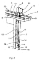
- FIG. 3 represents another possible embodiment of the invention, in which the striker 10 is mounted on the connecting rod 2 and therefore able to translate on the slide 6 in the second direction Tr, and the bolt 1 is mounted on the upright 12.
- the slope 31 of the ramp 3 is the opposite of that illustrated in FIGS. and 2
- the spring 18 (schematically shown) acts in thrust to tend to raise the rod 2
- the lug 19 in cooperation with the electromagnet 42 via the core 41 is mounted to push the roller 9 down when the electromagnet is controlled to allow the stall between the striker 10 and the bolt 1.
- the rest position of the electromagnet is that in which the tab 19 is in the upper position for example by means of a traction spring between it and the chassis 20.
Landscapes
- Physics & Mathematics (AREA)
- Electromagnetism (AREA)
- Power-Operated Mechanisms For Wings (AREA)
- Grates (AREA)
Applications Claiming Priority (1)
| Application Number | Priority Date | Filing Date | Title |
|---|---|---|---|
| FR0509799A FR2891296B1 (fr) | 2005-09-26 | 2005-09-26 | Dispositif d'accrochage et de decrochage entre un coulissant et un montant. |
Publications (2)
| Publication Number | Publication Date |
|---|---|
| EP1775402A2 true EP1775402A2 (de) | 2007-04-18 |
| EP1775402A3 EP1775402A3 (de) | 2007-06-06 |
Family
ID=35996359
Family Applications (1)
| Application Number | Title | Priority Date | Filing Date |
|---|---|---|---|
| EP06352017A Withdrawn EP1775402A3 (de) | 2005-09-26 | 2006-09-22 | Vorrichtung zum An- und Abkuppeln zwischen einen Schiebeflügel und einen Ständer |
Country Status (2)
| Country | Link |
|---|---|
| EP (1) | EP1775402A3 (de) |
| FR (1) | FR2891296B1 (de) |
Cited By (3)
| Publication number | Priority date | Publication date | Assignee | Title |
|---|---|---|---|---|
| EP3168396A1 (de) | 2015-11-12 | 2017-05-17 | Christian Chorin | Vorrichtung zum verriegeln für schiebetor, und entsprechendes schiebetor |
| EP3498960A1 (de) * | 2017-12-15 | 2019-06-19 | Liberda, Victor | Verriegelungsvorrichtung für eine tür, insbesondere schiebetür |
| WO2024167429A1 (pt) * | 2023-02-08 | 2024-08-15 | Jofebar, S.A. | Dispositivo para bloqueio e desbloqueio por deteção de toque de portas ou janelas deslizantes |
Citations (8)
| Publication number | Priority date | Publication date | Assignee | Title |
|---|---|---|---|---|
| US3390557A (en) * | 1965-10-06 | 1968-07-02 | Amerock Corp | Door latch |
| US3938836A (en) * | 1974-07-12 | 1976-02-17 | Smith Donald V | High strength bolt assembly for doors and the like |
| DE2455479A1 (de) * | 1974-11-23 | 1976-05-26 | Uhl Kg Geb | Beschlag zur verriegelung von schiebefenstern oder schiebetueren |
| US4902056A (en) * | 1986-09-16 | 1990-02-20 | Ferco International | Locking fitting in particular for the sliding leaf |
| EP0902140A1 (de) * | 1997-09-11 | 1999-03-17 | Kaba Gallenschütz GmbH | Türanlage mit Türverriegelung |
| DE19957033A1 (de) * | 1999-11-26 | 2001-05-31 | Lehmann Vertriebsgmbh | Rolljalousieschrank mit Drehzylinderschloß |
| US6585303B1 (en) * | 1999-09-27 | 2003-07-01 | R.R. Brink Locking Systems, Inc. | Door locking and operating mechanism |
| FR2860260A1 (fr) * | 2003-09-26 | 2005-04-01 | Brandt Ind | Serrure pour porte et porte coulissante equipee d'une telle serrure |
-
2005
- 2005-09-26 FR FR0509799A patent/FR2891296B1/fr not_active Expired - Fee Related
-
2006
- 2006-09-22 EP EP06352017A patent/EP1775402A3/de not_active Withdrawn
Patent Citations (8)
| Publication number | Priority date | Publication date | Assignee | Title |
|---|---|---|---|---|
| US3390557A (en) * | 1965-10-06 | 1968-07-02 | Amerock Corp | Door latch |
| US3938836A (en) * | 1974-07-12 | 1976-02-17 | Smith Donald V | High strength bolt assembly for doors and the like |
| DE2455479A1 (de) * | 1974-11-23 | 1976-05-26 | Uhl Kg Geb | Beschlag zur verriegelung von schiebefenstern oder schiebetueren |
| US4902056A (en) * | 1986-09-16 | 1990-02-20 | Ferco International | Locking fitting in particular for the sliding leaf |
| EP0902140A1 (de) * | 1997-09-11 | 1999-03-17 | Kaba Gallenschütz GmbH | Türanlage mit Türverriegelung |
| US6585303B1 (en) * | 1999-09-27 | 2003-07-01 | R.R. Brink Locking Systems, Inc. | Door locking and operating mechanism |
| DE19957033A1 (de) * | 1999-11-26 | 2001-05-31 | Lehmann Vertriebsgmbh | Rolljalousieschrank mit Drehzylinderschloß |
| FR2860260A1 (fr) * | 2003-09-26 | 2005-04-01 | Brandt Ind | Serrure pour porte et porte coulissante equipee d'une telle serrure |
Cited By (4)
| Publication number | Priority date | Publication date | Assignee | Title |
|---|---|---|---|---|
| EP3168396A1 (de) | 2015-11-12 | 2017-05-17 | Christian Chorin | Vorrichtung zum verriegeln für schiebetor, und entsprechendes schiebetor |
| FR3043711A1 (fr) * | 2015-11-12 | 2017-05-19 | Christian Chorin | Dispositif de verrouillage pour portail coulissant, et portail coulissant associe |
| EP3498960A1 (de) * | 2017-12-15 | 2019-06-19 | Liberda, Victor | Verriegelungsvorrichtung für eine tür, insbesondere schiebetür |
| WO2024167429A1 (pt) * | 2023-02-08 | 2024-08-15 | Jofebar, S.A. | Dispositivo para bloqueio e desbloqueio por deteção de toque de portas ou janelas deslizantes |
Also Published As
| Publication number | Publication date |
|---|---|
| FR2891296B1 (fr) | 2007-12-28 |
| EP1775402A3 (de) | 2007-06-06 |
| FR2891296A1 (fr) | 2007-03-30 |
Similar Documents
| Publication | Publication Date | Title |
|---|---|---|
| EP1178175B1 (de) | System zur Positionierung und Zusammenbau eines Fensters auf einem Fensterheber | |
| FR3071199A1 (fr) | Glissiere pour siege de vehicule et siege de vehicule comportant une telle glissiere | |
| EP1775402A2 (de) | Vorrichtung zum An- und Abkuppeln zwischen einen Schiebeflügel und einen Ständer | |
| WO2000001910A1 (fr) | Leve-vitre de porte de vehicule a fixation automatique a la vitre du curseur support de vitre | |
| FR2777588A1 (fr) | Dispositif de verrouillage pour ouvrant coulissant | |
| EP2317045A1 (de) | Eine C-förmige Vorrichtung zur Befestigung einer Antriebsstange | |
| EP0611864B1 (de) | Verriegelung für eine Schiebetür oder eines Schiebefenster | |
| EP0219589B1 (de) | Falttür | |
| FR2650025A1 (fr) | Ferrure de verrouillage d'un ouvrant coulissant d'une fenetre, porte ou analogue en profiles | |
| FR2733786A1 (fr) | Dispositif de blocage pour fenetres, portes ou analogues | |
| EP0715383A1 (de) | Anordnung zur Befestigung eines elektrisches Gerätes an einer Tragschiene | |
| FR2588605A1 (fr) | Systeme manoeuvrable d'arret d'un battant de volet et ensemble de crochetage dudit battant. | |
| EP0882861B1 (de) | Verriegelungsvorrichtung für einen Schiebeflügel | |
| FR2488318A1 (fr) | Serrure a larder du type trois points | |
| FR2540544A1 (fr) | Dispositif de reglage pour battants de fenetres, vantaux de portes ou autres elements du meme genre a ouverture a coulisse | |
| FR3055647A1 (fr) | Dispositif d'actionnement d'huisserie et huisserie comprenant un tel dispositif | |
| EP0607715B1 (de) | Schloss für Schiebetür oder Schiebefenster mit Hakenverriegelungssystem im geschlossenen Zustand | |
| FR2838474A1 (fr) | Fermeture mecanique pour portails motorises | |
| EP2320012B1 (de) | Verschluss für die Klappe eines Kastens | |
| EP1383980B1 (de) | Autonome motorantriebseinheit für ein schiebetor | |
| EP1359274A1 (de) | Verstellbarer Lüftungsanschlag für Öffnungen | |
| FR2696051A1 (fr) | Armoire à battant de porte équipé d'un détecteur de fermeture. | |
| EP1004735A1 (de) | Fehlbedienungssperre für Türe, Fenster oder dergleichen versehen mit einem Treibstangenverschluss oder einem Treibstangenschloss | |
| EP3619388B1 (de) | Schiebefenster mit einer abdichtungsvorrichtung | |
| EP2386706A1 (de) | Verrieglungsvorrichtung für halbfesten Fensterflügel |
Legal Events
| Date | Code | Title | Description |
|---|---|---|---|
| PUAI | Public reference made under article 153(3) epc to a published international application that has entered the european phase |
Free format text: ORIGINAL CODE: 0009012 |
|
| AK | Designated contracting states |
Kind code of ref document: A2 Designated state(s): AT BE BG CH CY CZ DE DK EE ES FI FR GB GR HU IE IS IT LI LT LU LV MC NL PL PT RO SE SI SK TR |
|
| AX | Request for extension of the european patent |
Extension state: AL BA HR MK YU |
|
| PUAL | Search report despatched |
Free format text: ORIGINAL CODE: 0009013 |
|
| AK | Designated contracting states |
Kind code of ref document: A3 Designated state(s): AT BE BG CH CY CZ DE DK EE ES FI FR GB GR HU IE IS IT LI LT LU LV MC NL PL PT RO SE SI SK TR |
|
| AX | Request for extension of the european patent |
Extension state: AL BA HR MK YU |
|
| 17P | Request for examination filed |
Effective date: 20071127 |
|
| 17Q | First examination report despatched |
Effective date: 20080114 |
|
| AKX | Designation fees paid |
Designated state(s): AT BE BG CH CY CZ DE DK EE ES FI FR GB GR HU IE IS IT LI LT LU LV MC NL PL PT RO SE SI SK TR |
|
| STAA | Information on the status of an ep patent application or granted ep patent |
Free format text: STATUS: THE APPLICATION IS DEEMED TO BE WITHDRAWN |
|
| 18D | Application deemed to be withdrawn |
Effective date: 20120403 |