EP1775389A1 - Loading apparatus - Google Patents
Loading apparatus Download PDFInfo
- Publication number
- EP1775389A1 EP1775389A1 EP04773116A EP04773116A EP1775389A1 EP 1775389 A1 EP1775389 A1 EP 1775389A1 EP 04773116 A EP04773116 A EP 04773116A EP 04773116 A EP04773116 A EP 04773116A EP 1775389 A1 EP1775389 A1 EP 1775389A1
- Authority
- EP
- European Patent Office
- Prior art keywords
- bucket
- lift arm
- link
- attachment
- cylinder
- Prior art date
- Legal status (The legal status is an assumption and is not a legal conclusion. Google has not performed a legal analysis and makes no representation as to the accuracy of the status listed.)
- Withdrawn
Links
Images



Classifications
-
- E—FIXED CONSTRUCTIONS
- E02—HYDRAULIC ENGINEERING; FOUNDATIONS; SOIL SHIFTING
- E02F—DREDGING; SOIL-SHIFTING
- E02F3/00—Dredgers; Soil-shifting machines
- E02F3/04—Dredgers; Soil-shifting machines mechanically-driven
- E02F3/28—Dredgers; Soil-shifting machines mechanically-driven with digging tools mounted on a dipper- or bucket-arm, i.e. there is either one arm or a pair of arms, e.g. dippers, buckets
- E02F3/34—Dredgers; Soil-shifting machines mechanically-driven with digging tools mounted on a dipper- or bucket-arm, i.e. there is either one arm or a pair of arms, e.g. dippers, buckets with bucket-arms, i.e. a pair of arms, e.g. manufacturing processes, form, geometry, material of bucket-arms directly pivoted on the frames of tractors or self-propelled machines
-
- E—FIXED CONSTRUCTIONS
- E02—HYDRAULIC ENGINEERING; FOUNDATIONS; SOIL SHIFTING
- E02F—DREDGING; SOIL-SHIFTING
- E02F3/00—Dredgers; Soil-shifting machines
- E02F3/04—Dredgers; Soil-shifting machines mechanically-driven
- E02F3/28—Dredgers; Soil-shifting machines mechanically-driven with digging tools mounted on a dipper- or bucket-arm, i.e. there is either one arm or a pair of arms, e.g. dippers, buckets
- E02F3/34—Dredgers; Soil-shifting machines mechanically-driven with digging tools mounted on a dipper- or bucket-arm, i.e. there is either one arm or a pair of arms, e.g. dippers, buckets with bucket-arms, i.e. a pair of arms, e.g. manufacturing processes, form, geometry, material of bucket-arms directly pivoted on the frames of tractors or self-propelled machines
- E02F3/3405—Dredgers; Soil-shifting machines mechanically-driven with digging tools mounted on a dipper- or bucket-arm, i.e. there is either one arm or a pair of arms, e.g. dippers, buckets with bucket-arms, i.e. a pair of arms, e.g. manufacturing processes, form, geometry, material of bucket-arms directly pivoted on the frames of tractors or self-propelled machines and comprising an additional linkage mechanism
- E02F3/3408—Dredgers; Soil-shifting machines mechanically-driven with digging tools mounted on a dipper- or bucket-arm, i.e. there is either one arm or a pair of arms, e.g. dippers, buckets with bucket-arms, i.e. a pair of arms, e.g. manufacturing processes, form, geometry, material of bucket-arms directly pivoted on the frames of tractors or self-propelled machines and comprising an additional linkage mechanism of the parallelogram-type
-
- Y—GENERAL TAGGING OF NEW TECHNOLOGICAL DEVELOPMENTS; GENERAL TAGGING OF CROSS-SECTIONAL TECHNOLOGIES SPANNING OVER SEVERAL SECTIONS OF THE IPC; TECHNICAL SUBJECTS COVERED BY FORMER USPC CROSS-REFERENCE ART COLLECTIONS [XRACs] AND DIGESTS
- Y10—TECHNICAL SUBJECTS COVERED BY FORMER USPC
- Y10S—TECHNICAL SUBJECTS COVERED BY FORMER USPC CROSS-REFERENCE ART COLLECTIONS [XRACs] AND DIGESTS
- Y10S414/00—Material or article handling
- Y10S414/13—Handlers utilizing parallel links
Definitions
- the invention relates to a loading apparatus (loader) attached to a working vehicle so as to be used for loading sand, bulk and so on.
- a front loader serving as a loading apparatus attached to a working vehicle, includes a pair of left and right lift arms, a bucket connected to tips of the lift arms, a cylinder for lifting the lift arms, and a cylinder for rotating the bucket.
- a normal front loader disclosed in Japanese Laid Open Gazette No. Hei 8-27842 is attached onto brackets secured on left and right sides of a rear portion of a bonnet of a tractor, serving as a working vehicle.
- the tractor is provided with a cylinder for rotating the lift arms below the lift arms of the front loader, and is provided with a bucket link below the lift arms.
- An intermediate link is attached onto an upper portion of each of the lift arms.
- the bucket link extended from the bracket is connected through the intermediate link to a bucket cylinder, which is telescopically moved for swinging the bucket.
- the linkage for swinging the bucket is formed straight above the lift arms.
- the linkage for swinging the bucket of the front loader includes two rotatable members attached to each of the lift arms between the bucket and each of the brackets secured on the respective sides of the bonnet of the tractor, thereby being prevented from interfering with the lift arms.
- the pivot points of the lift arms are required to move toward the working vehicle, however, the lift arms have to be prevented from interfering with wheels of the working vehicle. If the lift arms are curved to be prevented from interfering with the wheels, the intermediate link for relaying the action of the bucket cylinder has to be expanded so as to prevent the linkage for the bucket from interfering with the lift arms. The expansion of the intermediate link increases the weight of the loader, and narrows an operator's ken for viewing the bucket.
- the invention solves the above problems by the following ways:
- a bucket attached to the attachment is provided at a lower portion thereof with a pawl.
- the pawl is positioned before a pivotal point of the bucket when the lift arm is positioned at a lower limit of its rotatable range.
- the bracket fixed on the vehicle includes pivotal centers of the lift arm, the bucket cylinder and the lift arm cylinder, disposed on the same plane.
- the lift arm and the bucket link are made of plates.
- the lift arm is provided with a tilt stopper and a dump stopper for the bucket attached to the attachment.
- a loading apparatus comprises: a bracket fixed on a vehicle; a lift arm pivoted at one end thereof onto the bracket; a lift arm cylinder for vertically swinging the lift arm; an attachment vertically swingably pivoted onto a tip of the lift arm; a bucket cylinder; and a bucket link connected to the attachment for transmitting a telescopic movement of the bucket cylinder to the attachment.
- An intermediate link including a pair of left and right plates, is pivoted onto the lift arm.
- the bucket link and the bucket cylinder are connected to the intermediate link, so that the lift arm and the bucket link are offset from each other between the plates of the intermediate link.
- a loading apparatus comprises: a bracket fixed on a vehicle; a lift arm pivoted at one end thereof onto the bracket; a lift arm cylinder for vertically swinging the lift arm; an attachment vertically swingably pivoted onto a tip of the lift arm; a bucket cylinder; and a bucket link connected to the attachment for transmitting a telescopic movement of the bucket cylinder to the attachment. Since the bucket link is laterally offset from the lift arm, the visibility of a bucket attached to the attachment is improved, and a sufficient rotatable range of the bucket is ensured without interference of the linkage of the loading apparatus with other members. Further, the linkage for swinging the attachment is simplified with pivot points reduced in number, while ensuring a sufficient strength.
- a bucket attached to the attachment is provided at a lower portion thereof with a pawl, which is positioned before a pivotal point of the bucket when the lift arm is positioned at a lower limit of its rotatable range, the bucket cylinder is protected from excessive load when a side of the working vehicle onto which the loading apparatus is attached is raised while the bucket is landed on the earth.
- the bracket fixed on the vehicle since the bracket fixed on the vehicle includes pivotal centers of the lift arm, the bucket cylinder and the lift arm cylinder, disposed on the same plane, the lateral width of the linkage of the loading apparatus is reduced so as to improve the visibility of the bucket attached to the attachment.
- the load onto the bracket from the lift arm, the bucket cylinder and the lift arm cylinder is reduced because the load is hard to be applied onto the bracket in the direction of twisting the bracket.
- the lateral width of the linkage of the loading apparatus is reduced so as to improve the visibility of the bucket attached to the attachment in the case where the linkage overlaps in side view by vertically moving the lift arm.
- the structure of the lift arm with the stoppers is simple, and the stoppers provided on the lift arm are advantageous in durability.
- the structure of the loading apparatus including the lift arm is simple.
- a loading apparatus comprises: a bracket fixed on a vehicle; a lift arm pivoted at one end thereof onto the bracket; a lift arm cylinder for vertically swinging the lift arm; an attachment vertically swingably pivoted onto a tip of the lift arm; a bucket cylinder; and a bucket link connected to the attachment for transmitting a telescopic movement of the bucket cylinder to the attachment.
- An intermediate link including a pair of left and right plates, is pivoted onto the lift arm, and the bucket link and the bucket cylinder are connected to the intermediate link, so that the lift arm and the bucket link are offset from each other between the plates of the intermediate link.
- the loading apparatus is simple in structure, an operator's ken for viewing a bucket or the like attached to the attachment is expanded, and sufficient strengths of components of the loading apparatus are ensured. Due to the offset of the lift arm and the bucket link between the pair of plates, the bucket link is advantageous in rigidity, durability and simplicity in comparison with a curved bucket link.
- a loading apparatus attached to a working vehicle is configured so as to have a simple linkage for lifting and swinging an attachment, and to have a large workable range while preventing components of the linkage from interfering with each other.
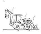
- FIG. 1 is a side view of a loader attached to a working vehicle.
- a working vehicle 1 is a backhoe loader, provided with front wheels 31 and rear wheels 32.
- Working vehicle 1 is equipped with a loader 2, serving as a loading apparatus, and an excavator 3.
- a pair of brackets 4 are disposed on respective left and right sides of a bonnet of working vehicle 1, and fixed to a body frame of working vehicle 1.
- Loader 2 is attached to brackets 4 at a front portion of working vehicle 1 so as to serve as a front loader.
- each bracket 4 On each bracket 4 are disposed a pivot center 11 g for a lift arm 11, a pivot center 14b for a bucket cylinder 14 and a pivot center 12b for a lift arm cylinder 12.
- Pivot center 11 g for lift arm 11 is disposed forward and downward from center pivot 14b for bucket cylinder 14.
- Pivot center 12b for lift arm cylinder 12 is disposed forward and downward from center pivot 11 g for lift arm 11.
- Working vehicle 1 includes steerable wheels below lift arms 11 of loader 2.
- Each of lift arms 11 is doglegged when viewed in side, so as to have a fore-and-aft middle portion above a straight line extended between both ends thereof, thereby ensuring a space therebelow for turning the steerable wheels.
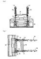
- FIG. 2 is a side view of the loader; Fig. 3 is a front view of the loader; Fig. 4 is a rear view of the loader; Fig. 5 is a plan view of the loader; and Fig. 6 is a perspective view of the loader.
- Loader 2 includes lift arms 11, lift arm cylinders 12, a bucket 18, bucket links 15, intermediate links 13, bucket cylinders 14 and others. Each of lift arms 11, each of bucket cylinders 14, and each of lift arm cylinders 12 are pivoted at rear ends thereof onto each of brackets 4. Lift arms 11 are vertically rotated by respective lift arm cylinders 12. Bucket 18 is swung by bucket cylinders 14 connected to respective bucket links 15 through respective intermediate links 13.
- the pair of lift arms 11 are disposed on respective left and right sides of working vehicle 1.
- Each of lift arms 11 is extended forwardly and downwardly slantwise in a side view, bent downward at the middle portion thereof, and bent forward at the lower front portion thereof, so as to be substantially S-shaped.
- Each of bucket cylinders 14, each of intermediate links 13 and each of bucket links 15 are disposed above each of lift arms 11.
- Each of lift arm cylinders 12 is disposed below each of lift arms 11.
- Bucket 18 is attached to tips of lift arms 11 through respective attachments 19.
- Bucket cylinder 14 and lift arm cylinder 12 are spaced from corresponding lift arm 11, so that the space between bucket cylinder 14 and lift arm 11 and the space between lift arm cylinder 12 and lift arm 11 are adapted for disposing a device for preventing the corresponding members from falling, for instance. In this way, various devices can be disposed in the spaces to be attached to loader 2, while ensuring the compactness of loader 2.
- Left and right lift arms 11 are connected at lower front portions thereof to each other through reinforcing members 16 so as to enhance the rigidity for supporting bucket 18.
- front and rear reinforcing members 16 are disposed in parallel to each other and extended laterally so as to connect left and right lift arms 11 to each other.
- the pair of reinforcing members 16 increase effective sectional areas for ensuring the rigidity, thereby serving as a simple and light structure for improving the rigidity of supporting bucket 18.
- a back surface of bucket 18 is adapted to be attached or detached to and from attachments 19.
- Each of attachments 19 is swingably pivoted onto corresponding lift arm 11 through a connection pin 11d.
- Each of bucket links 15 is pivoted at a tip thereof onto an upper portion of corresponding attachment 19 through a connection pin 15b. Therefore, bucket 18 is swung together with attachments 19 by moving bucket links 15 relative to lift arms 11.
- Each of intermediate links 13 is pivoted at a lower end portion thereof onto the fore-and-aft middle portion of corresponding lift arm 11.
- Each of bucket links 15 is pivoted at a rear end thereof to an upper front portion of corresponding intermediate link 13.
- a tip of a piston rod of each of bucket cylinders 14 is pivoted to an upper rear portion of corresponding intermediate link 13.
- Each of intermediate links 13 includes a pair of substantially triangular plates. The rear end of bucket link 15, bucket cylinder 14 and lift arm 11 are disposed between the two plates of intermediate link 13 so as to be connected to intermediate link 13.
- Bucket link 15 is disposed in the space in intermediate link 13, so as to be easily offset from lift arm 11.
- FIG. 7 is a side view of a structure of connecting an attachment.
- Fig. 8 is a front view partly in section of arrangement of a bucket link and a lift arm.
- Fig. 9 illustrates a bucket while it is tilting.
- Fig. 9(a) is a side view of the entire loader while the bucket is tilting, and
- Fig. 9(b) is a side view partly in section of a portion of the loader supporting the bucket while the bucket is tilting.
- Fig. 10 illustrates the bucket while it is dumping.
- Fig. 10(a) is a side view of the entire loader while the bucket is dumping, and Fig.
- FIG. 10(b) is a side view partly in section of the portion of the loader supporting the bucket while the bucket is dumping.
- the tip portions of lift arms 11 and the tip portions of bucket links 15 are adapted to support bucket 18.
- Lift arms 11 and bucket links 15 are pivotally connected to respective attachments 19, and bucket 18 is attached to attachments 19.
- Each of attachments 19 is connected to corresponding lift arm 11 through pin 11d.
- Each of bucket links 15 is connected to corresponding attachment 19 through pin 15b.
- Pins 11d and 15b are extended to have lateral axes.
- Each of pins 11d is fitted into attachment 19 and lift arm 11.
- Each of pins 15d is fitted into attachment 19 and bucket link 15. In this way, lift arm 11 and bucket link 15 constitute a parallel linkage.
- Attachment 19 and intermediate link 13 constitute a parallel linkage.
- Each of lift arms 11 is formed at front portions with a pair of projections, i.e., a lower projection formed on the bottom side so as to serve as a stopper 11e, and an upper projection formed on the top side so as to serve as a stopper 11b, thereby restricting the rotation of bucket 18.
- each of bucket links 15 is disposed on the outside of corresponding lift arm 11.
- Bucket link 15 is offset from lift arm 11 as shown in Fig. 8.
- Bucket link 15 is disposed so as not to vertically (in a plan view) overlap lift arm 11.
- Each lift arm 11 is disposed at the lateral middle position between the twin plates of intermediate link 13
- each of bucket links 15 is disposed on the outside of lift arm 11 between the twin plates of intermediate link 13. Therefore, lift arms 11 and bucket links 15 are prevented from interfering with each other during the lifting and swinging of bucket 18.
- Another design for preventing bucket links 15 from interfering with link arms 11 is unnecessary, thereby increasing the freedom degree in designing bucket links 15 for swinging bucket 18, and ensuring a large rotatable range of bucket 18.
- each of bucket links 15 can be shaped in a nearly rectilinear shape, such as to be light and simple while ensuring a sufficient rigidity.
- Each of lift arms 11 and each of bucket arms 15 are made of plates, so that their lateral widths are small while bucket link 15 overlaps lift arm 11 in a side view during tilting of bucket 18, and that they are rectilinearly connected to each other between corresponding intermediate link 13 and bucket 18, thereby improving the operator's ken for viewing bucket 18 over loader 2.
- loader 2 is lightened at the side thereof toward bucket 18 so as to reduce the moment applied when bucket 18 is vertically moved.
- stoppers 11c serve as tilt stoppers. Due to the above-mentioned offset of bucket links 15 from lift arms 11, stoppers 11c come to abut against respective pins 15b without interference of lift arms 11 with bucket links 15. Each of lift arms 11 is formed integrally with stopper 11c, thereby providing simple and durable stopper 11c.
- Each of stoppers 11e is formed on the bottom surface of the tip portion of lift arm 11 so as to have a downward projecting flat surface.
- Each of stoppers 19b is extended laterally from a bracket of attachment 19 supporting pins 11d and 15b.
- a flat surface of each of stoppers 19b abuts against the flat surface of corresponding stopper 11e of lift arm 11. Due to the offset of bucket links 15 from lift arms 11, stoppers 11e come to abut against respective stoppers 19b without interference of lift arms 11 with bucket links 15. Namely, stoppers 11e serve as dump stoppers.
- Each of lift arms 11 is formed integrally with stopper 11e for limiting the rotation angle of bucket 18, thereby providing simple and durable stopper 11e.
- FIG. 11 illustrates a bucket cylinder when its stroke is determined.
- Fig. 11(a) is a diagram of the bucket cylinder whose stroke reaches the maximum.
- Fig. 11(b) is a diagram of the bucket cylinder when the bucket is excessively rotated.
- the downward rotation of bucket cylinders 14 is limited at a position where pawls 18b provided on the bottom edge of bucket 18 are disposed just under respective pins 1 1d, so as to prevent pawls 18b from further moving toward working vehicle 1.
- the maximum stroke of each of bucket cylinders 14 has a length La when lift arms 11 are lowered and pawls 18b reach the position just below pins 11d.
- a stopper may be provided on the rod of bucket cylinder 14, so that, when the cylinder abuts against the stopper, the stroke of the cylinder is defined as the maximum stroke, and prevented from exceeding length La.
- bucket cylinders 14 are prevented from receiving excessive load when bucket 18 is pressed against the ground surface and the loader is used for lifting up the working vehicle. If the vehicle is lifted up by the loader in the state that bucket 18 is disposed so as to rotate pawls 18b toward the vehicle from the position just below pins 11d, it is suggested that the weight of the vehicle and the working shock are transmitted to bucket cylinders 14 so as to cause a leak of fluid from bucket cylinders 14. In this regard, with respect to the angle of bucket 18, the force is gradually applied as bucket 18 is rotated toward the working vehicle. The force is transmitted through bucket links 15 to bucket cylinders 14 so as to extend the rods of bucket cylinders 14, so that bucket cylinders 14 may be excessively loaded and damaged when they are extended.
- FIG. 12 illustrates a bucket link according to a second embodiment.
- Fig. 12(a) is a side view of a loader according to the second embodiment
- Fig. 12(b) is a side view partly in section of the bucket link.
- Fig. 13 is a front view partly in section of the bucket link according to the second embodiment.
- Each of bucket links 25 has a not-pivoted portion sectionally formed in a reversed U-shape when viewed in front. Referring to Fig. 13, in the reversed U-shaped section, a pair of plates 25c are extended downward from a bottom surface of a horizontal plate 25b. Each of lift arms 11 is disposed between the downwardly extended plates.
- a bucket link 25 is improved in strength while it is prevented from interfering with lift arm 11. Further, the sectional area of bucket link 25 for ensuring the rigidity is increased while bucket link 25 is vertically minimized. Therefore, the freedom degree of designing the linkage for swinging the bucket is enhanced.
- a bucket link may be T-shaped in a sectional front view.
- a loading apparatus is advantageously applied to a working vehicle, especially, an agricultural working vehicle or a construction vehicle, such as to load sand, bulk or the like, as mentioned above.
Landscapes
- Engineering & Computer Science (AREA)
- Mechanical Engineering (AREA)
- Mining & Mineral Resources (AREA)
- Civil Engineering (AREA)
- General Engineering & Computer Science (AREA)
- Structural Engineering (AREA)
- Shovels (AREA)
- Forklifts And Lifting Vehicles (AREA)
- Load-Engaging Elements For Cranes (AREA)
Abstract
Description
- The invention relates to a loading apparatus (loader) attached to a working vehicle so as to be used for loading sand, bulk and so on.
- Generally, a front loader, serving as a loading apparatus attached to a working vehicle, includes a pair of left and right lift arms, a bucket connected to tips of the lift arms, a cylinder for lifting the lift arms, and a cylinder for rotating the bucket.
A normal front loader disclosed inJapanese Laid Open Gazette No. Hei 8-27842 - To reduce the whole length of the working vehicle, including the front loader equipped on the vehicle, the pivot points of the lift arms are required to move toward the working vehicle, however, the lift arms have to be prevented from interfering with wheels of the working vehicle.
If the lift arms are curved to be prevented from interfering with the wheels, the intermediate link for relaying the action of the bucket cylinder has to be expanded so as to prevent the linkage for the bucket from interfering with the lift arms. The expansion of the intermediate link increases the weight of the loader, and narrows an operator's ken for viewing the bucket. - Problems to be solved are the interference of the lift arms with wheels and the expansion of the intermediate link caused when the working vehicle with the loader is minimized in the whole length.
- The invention solves the above problems by the following ways:
- A loading apparatus according to the invention comprises: a bracket fixed on a vehicle; a lift arm pivoted at one end thereof onto the bracket; a lift arm cylinder for vertically swinging the lift arm; an attachment vertically swingably pivoted onto a tip of the lift arm; a bucket cylinder; and a bucket link connected to the attachment for transmitting a telescopic movement of the bucket cylinder to the attachment. The bucket link is laterally offset from the lift arm.
- In the loading apparatus according to the invention, a bucket attached to the attachment is provided at a lower portion thereof with a pawl. The pawl is positioned before a pivotal point of the bucket when the lift arm is positioned at a lower limit of its rotatable range.
- In the loading apparatus according to the invention, the bracket fixed on the vehicle includes pivotal centers of the lift arm, the bucket cylinder and the lift arm cylinder, disposed on the same plane.
- In the loading apparatus according to the invention, the lift arm and the bucket link are made of plates.
- In the loading apparatus according to the invention, the lift arm is provided with a tilt stopper and a dump stopper for the bucket attached to the attachment.
- A loading apparatus according to the invention comprises: a bracket fixed on a vehicle; a lift arm pivoted at one end thereof onto the bracket; a lift arm cylinder for vertically swinging the lift arm; an attachment vertically swingably pivoted onto a tip of the lift arm; a bucket cylinder; and a bucket link connected to the attachment for transmitting a telescopic movement of the bucket cylinder to the attachment. An intermediate link, including a pair of left and right plates, is pivoted onto the lift arm. The bucket link and the bucket cylinder are connected to the intermediate link, so that the lift arm and the bucket link are offset from each other between the plates of the intermediate link.
- According to the invention, a loading apparatus comprises: a bracket fixed on a vehicle; a lift arm pivoted at one end thereof onto the bracket; a lift arm cylinder for vertically swinging the lift arm; an attachment vertically swingably pivoted onto a tip of the lift arm; a bucket cylinder; and a bucket link connected to the attachment for transmitting a telescopic movement of the bucket cylinder to the attachment. Since the bucket link is laterally offset from the lift arm, the visibility of a bucket attached to the attachment is improved, and a sufficient rotatable range of the bucket is ensured without interference of the linkage of the loading apparatus with other members. Further, the linkage for swinging the attachment is simplified with pivot points reduced in number, while ensuring a sufficient strength.
- In the loading apparatus according to the invention, since a bucket attached to the attachment is provided at a lower portion thereof with a pawl, which is positioned before a pivotal point of the bucket when the lift arm is positioned at a lower limit of its rotatable range, the bucket cylinder is protected from excessive load when a side of the working vehicle onto which the loading apparatus is attached is raised while the bucket is landed on the earth.
- In the loading apparatus according to the invention, since the bracket fixed on the vehicle includes pivotal centers of the lift arm, the bucket cylinder and the lift arm cylinder, disposed on the same plane, the lateral width of the linkage of the loading apparatus is reduced so as to improve the visibility of the bucket attached to the attachment. The load onto the bracket from the lift arm, the bucket cylinder and the lift arm cylinder is reduced because the load is hard to be applied onto the bracket in the direction of twisting the bracket.
- In the loading apparatus according to the invention, since the lift arm and the bucket link are made of plates, the lateral width of the linkage of the loading apparatus is reduced so as to improve the visibility of the bucket attached to the attachment in the case where the linkage overlaps in side view by vertically moving the lift arm.
- In the loading apparatus according to the invention, since the lift arm is provided with a tilt stopper and a dump stopper for the bucket attached to the attachment, the structure of the lift arm with the stoppers is simple, and the stoppers provided on the lift arm are advantageous in durability. As a result, the structure of the loading apparatus including the lift arm is simple.
- According to the invention, a loading apparatus comprises: a bracket fixed on a vehicle; a lift arm pivoted at one end thereof onto the bracket; a lift arm cylinder for vertically swinging the lift arm; an attachment vertically swingably pivoted onto a tip of the lift arm; a bucket cylinder; and a bucket link connected to the attachment for transmitting a telescopic movement of the bucket cylinder to the attachment. An intermediate link, including a pair of left and right plates, is pivoted onto the lift arm, and the bucket link and the bucket cylinder are connected to the intermediate link, so that the lift arm and the bucket link are offset from each other between the plates of the intermediate link. Therefore, the loading apparatus is simple in structure, an operator's ken for viewing a bucket or the like attached to the attachment is expanded, and sufficient strengths of components of the loading apparatus are ensured. Due to the offset of the lift arm and the bucket link between the pair of plates, the bucket link is advantageous in rigidity, durability and simplicity in comparison with a curved bucket link.
-
- Fig. 1 is a side view of a loader attached to a working vehicle.
- Fig. 2 is a side view of the loader.
- Fig. 3 is a front view of the loader.
- Fig. 4 is a rear view of the loader.
- Fig. 5 is a plan view of the loader.
- Fig. 6 is a perspective view of the loader.
- Fig. 7 is a side view of a structure of connecting an attachment.
- Fig. 8 is a front view partly in section of arrangement of a bucket link and a lift arm.
- Fig. 9 illustrates a bucket while it is tilting.
- Fig. 10 illustrates the bucket while it is dumping.
- Fig. 11 illustrates a bucket cylinder when its stroke is determined.
- Fig. 12 illustrates a bucket link according to a second embodiment.
- Fig. 13 is a front view partly in section of the bucket link according to the second embodiment.
-
- 1
- Working Vehicle
- 2
- Loader
- 3
- Excavator
- 4
- Bracket
- 11
- Lift Arm
- 12
- Lift Arm Cylinder
- 13
- Intermediate Link
- 14
- Bucket Cylinder
- 15
- Bucket Link
- 16
- Reinforcing Member
- 18
- Bucket
- 19
- Attachment
- A loading apparatus attached to a working vehicle is configured so as to have a simple linkage for lifting and swinging an attachment, and to have a large workable range while preventing components of the linkage from interfering with each other.
- An embodiment of the invention will be described with reference to the drawings.
Fig. 1 is a side view of a loader attached to a working vehicle.
A working vehicle 1 is a backhoe loader, provided withfront wheels 31 andrear wheels 32. Working vehicle 1 is equipped with aloader 2, serving as a loading apparatus, and anexcavator 3. A pair ofbrackets 4 are disposed on respective left and right sides of a bonnet of working vehicle 1, and fixed to a body frame of working vehicle 1.
Loader 2 is attached tobrackets 4 at a front portion of working vehicle 1 so as to serve as a front loader. On eachbracket 4 are disposed apivot center 11 g for alift arm 11, apivot center 14b for abucket cylinder 14 and apivot center 12b for alift arm cylinder 12.Pivot center 11 g forlift arm 11 is disposed forward and downward fromcenter pivot 14b forbucket cylinder 14.Pivot center 12b forlift arm cylinder 12 is disposed forward and downward fromcenter pivot 11 g forlift arm 11.
Working vehicle 1 includes steerable wheels belowlift arms 11 ofloader 2. Each oflift arms 11 is doglegged when viewed in side, so as to have a fore-and-aft middle portion above a straight line extended between both ends thereof, thereby ensuring a space therebelow for turning the steerable wheels. - A structure of
loader 2 will be described.
Fig. 2 is a side view of the loader; Fig. 3 is a front view of the loader; Fig. 4 is a rear view of the loader; Fig. 5 is a plan view of the loader; and Fig. 6 is a perspective view of the loader.
Loader 2 includes liftarms 11,lift arm cylinders 12, abucket 18, bucket links 15,intermediate links 13,bucket cylinders 14 and others.
Each oflift arms 11, each ofbucket cylinders 14, and each oflift arm cylinders 12 are pivoted at rear ends thereof onto each ofbrackets 4.
Liftarms 11 are vertically rotated by respectivelift arm cylinders 12.Bucket 18 is swung bybucket cylinders 14 connected torespective bucket links 15 through respectiveintermediate links 13. - The pair of
lift arms 11 are disposed on respective left and right sides of working vehicle 1. Each oflift arms 11 is extended forwardly and downwardly slantwise in a side view, bent downward at the middle portion thereof, and bent forward at the lower front portion thereof, so as to be substantially S-shaped. Each ofbucket cylinders 14, each ofintermediate links 13 and each ofbucket links 15 are disposed above each oflift arms 11. Each oflift arm cylinders 12 is disposed below each oflift arms 11.Bucket 18 is attached to tips oflift arms 11 throughrespective attachments 19.
Bucket cylinder 14 andlift arm cylinder 12 are spaced from correspondinglift arm 11, so that the space betweenbucket cylinder 14 andlift arm 11 and the space betweenlift arm cylinder 12 andlift arm 11 are adapted for disposing a device for preventing the corresponding members from falling, for instance. In this way, various devices can be disposed in the spaces to be attached toloader 2, while ensuring the compactness ofloader 2.
Left and right liftarms 11 are connected at lower front portions thereof to each other through reinforcingmembers 16 so as to enhance the rigidity for supportingbucket 18. As shown in Fig. 5, front and rear reinforcingmembers 16 are disposed in parallel to each other and extended laterally so as to connect left and right liftarms 11 to each other. The pair of reinforcingmembers 16 increase effective sectional areas for ensuring the rigidity, thereby serving as a simple and light structure for improving the rigidity of supportingbucket 18. - A back surface of
bucket 18 is adapted to be attached or detached to and fromattachments 19. Each ofattachments 19 is swingably pivoted ontocorresponding lift arm 11 through aconnection pin 11d. Each ofbucket links 15 is pivoted at a tip thereof onto an upper portion of correspondingattachment 19 through aconnection pin 15b. Therefore,bucket 18 is swung together withattachments 19 by movingbucket links 15 relative to liftarms 11. - Each of
intermediate links 13 is pivoted at a lower end portion thereof onto the fore-and-aft middle portion ofcorresponding lift arm 11. Each ofbucket links 15 is pivoted at a rear end thereof to an upper front portion of correspondingintermediate link 13. A tip of a piston rod of each ofbucket cylinders 14 is pivoted to an upper rear portion of correspondingintermediate link 13. Each ofintermediate links 13 includes a pair of substantially triangular plates. The rear end ofbucket link 15,bucket cylinder 14 andlift arm 11 are disposed between the two plates ofintermediate link 13 so as to be connected tointermediate link 13.
Bucket link 15 is disposed in the space inintermediate link 13, so as to be easily offset fromlift arm 11. - A structure of
bucket link 15 andlift arm 11 will be described with reference to Figs. 7 to 10.
Fig. 7 is a side view of a structure of connecting an attachment. Fig. 8 is a front view partly in section of arrangement of a bucket link and a lift arm. Fig. 9 illustrates a bucket while it is tilting. Fig. 9(a) is a side view of the entire loader while the bucket is tilting, and Fig. 9(b) is a side view partly in section of a portion of the loader supporting the bucket while the bucket is tilting.
Fig. 10 illustrates the bucket while it is dumping. Fig. 10(a) is a side view of the entire loader while the bucket is dumping, and Fig. 10(b) is a side view partly in section of the portion of the loader supporting the bucket while the bucket is dumping.
The tip portions oflift arms 11 and the tip portions ofbucket links 15 are adapted to supportbucket 18. Liftarms 11 andbucket links 15 are pivotally connected torespective attachments 19, andbucket 18 is attached toattachments 19. Each ofattachments 19 is connected tocorresponding lift arm 11 throughpin 11d. Each ofbucket links 15 is connected to correspondingattachment 19 throughpin 15b.Pins pins 11d is fitted intoattachment 19 andlift arm 11. Each of pins 15d is fitted intoattachment 19 andbucket link 15. In this way,lift arm 11 and bucket link 15 constitute a parallel linkage.Attachment 19 andintermediate link 13 constitute a parallel linkage. Whenbucket cylinders 14 are stationary andlift arm cylinders 12 are telescopically moved,bucket 18 is vertically moved while substantially keeping an angle thereof.
Each oflift arms 11 is formed at front portions with a pair of projections, i.e., a lower projection formed on the bottom side so as to serve as astopper 11e, and an upper projection formed on the top side so as to serve as astopper 11b, thereby restricting the rotation ofbucket 18. - In
loader 2, serving as the loading apparatus, each ofbucket links 15 is disposed on the outside ofcorresponding lift arm 11.Bucket link 15 is offset fromlift arm 11 as shown in Fig. 8.Bucket link 15 is disposed so as not to vertically (in a plan view) overlaplift arm 11. Eachlift arm 11 is disposed at the lateral middle position between the twin plates ofintermediate link 13, each ofbucket links 15 is disposed on the outside oflift arm 11 between the twin plates ofintermediate link 13.
Therefore, liftarms 11 andbucket links 15 are prevented from interfering with each other during the lifting and swinging ofbucket 18. Another design for preventingbucket links 15 from interfering withlink arms 11 is unnecessary, thereby increasing the freedom degree in designingbucket links 15 for swingingbucket 18, and ensuring a large rotatable range ofbucket 18. Further, each ofbucket links 15 can be shaped in a nearly rectilinear shape, such as to be light and simple while ensuring a sufficient rigidity.
Each oflift arms 11 and each ofbucket arms 15 are made of plates, so that their lateral widths are small while bucket link 15 overlaps liftarm 11 in a side view during tilting ofbucket 18, and that they are rectilinearly connected to each other between correspondingintermediate link 13 andbucket 18, thereby improving the operator's ken for viewingbucket 18 overloader 2. Further,loader 2 is lightened at the side thereof towardbucket 18 so as to reduce the moment applied whenbucket 18 is vertically moved. - A structure of the stoppers for limiting the tilting rotation of bucket 18 (in the direction for scooping up) will now be described.
Whenbucket 18 is rotated toward working vehicle 1 in the state that liftarms 11 are lowered,bucket 18 "tilts", and each ofpins 15b connecting attachment 19 tobucket link 15 abuts againststopper 11c oflift arm 11 so as to limit the tilting rotation ofbucket 18. Namely,stoppers 11c serve as tilt stoppers.
Due to the above-mentioned offset ofbucket links 15 fromlift arms 11,stoppers 11c come to abut againstrespective pins 15b without interference oflift arms 11 withbucket links 15. Each oflift arms 11 is formed integrally withstopper 11c, thereby providing simple anddurable stopper 11c. - A structure of the stoppers for limiting the dumping rotation of bucket 18 (in the direction for dumping) will now be described.
Each ofstoppers 11e is formed on the bottom surface of the tip portion oflift arm 11 so as to have a downward projecting flat surface. Whenbucket 18 is rotated opposite to working vehicle 1 in the state that liftarms 11 are lowered,bucket 18 "dumps", and each of stoppers 19b ofattachments 19 abuts againststopper 11e oflift arm 11 so as to limit the dumping rotation ofbucket 18. - Each of stoppers 19b is extended laterally from a bracket of
attachment 19 supportingpins bucket 18 dumps, a flat surface of each of stoppers 19b abuts against the flat surface of correspondingstopper 11e oflift arm 11.
Due to the offset ofbucket links 15 fromlift arms 11,stoppers 11e come to abut against respective stoppers 19b without interference oflift arms 11 withbucket links 15. Namely,stoppers 11e serve as dump stoppers.
Each oflift arms 11 is formed integrally withstopper 11e for limiting the rotation angle ofbucket 18, thereby providing simple anddurable stopper 11e. - A structure of
bucket cylinders 14 will now be described.
Fig. 11 illustrates a bucket cylinder when its stroke is determined. Fig. 11(a) is a diagram of the bucket cylinder whose stroke reaches the maximum. Fig. 11(b) is a diagram of the bucket cylinder when the bucket is excessively rotated.
In the state that liftarms 11 have been rotated downward, the downward rotation ofbucket cylinders 14 is limited at a position wherepawls 18b provided on the bottom edge ofbucket 18 are disposed just under respective pins 1 1d, so as to preventpawls 18b from further moving toward working vehicle 1. In this regard, the maximum stroke of each ofbucket cylinders 14 has a length La when liftarms 11 are lowered andpawls 18b reach the position just belowpins 11d. To limit the stroke of each ofbucket cylinders 14, a stopper may be provided on the rod ofbucket cylinder 14, so that, when the cylinder abuts against the stopper, the stroke of the cylinder is defined as the maximum stroke, and prevented from exceeding length La. - Therefore,
bucket cylinders 14 are prevented from receiving excessive load whenbucket 18 is pressed against the ground surface and the loader is used for lifting up the working vehicle. If the vehicle is lifted up by the loader in the state thatbucket 18 is disposed so as to rotatepawls 18b toward the vehicle from the position just belowpins 11d, it is suggested that the weight of the vehicle and the working shock are transmitted tobucket cylinders 14 so as to cause a leak of fluid frombucket cylinders 14. In this regard, with respect to the angle ofbucket 18, the force is gradually applied asbucket 18 is rotated toward the working vehicle. The force is transmitted throughbucket links 15 tobucket cylinders 14 so as to extend the rods ofbucket cylinders 14, so thatbucket cylinders 14 may be excessively loaded and damaged when they are extended. - A second embodiment of the invention will be described with reference to Figs. 12 and 13.
Fig. 12 illustrates a bucket link according to a second embodiment. Fig. 12(a) is a side view of a loader according to the second embodiment, and Fig. 12(b) is a side view partly in section of the bucket link. Fig. 13 is a front view partly in section of the bucket link according to the second embodiment.
Each ofbucket links 25 has a not-pivoted portion sectionally formed in a reversed U-shape when viewed in front. Referring to Fig. 13, in the reversed U-shaped section, a pair ofplates 25c are extended downward from a bottom surface of ahorizontal plate 25b. Each oflift arms 11 is disposed between the downwardly extended plates. Such abucket link 25 is improved in strength while it is prevented from interfering withlift arm 11. Further, the sectional area ofbucket link 25 for ensuring the rigidity is increased while bucket link 25 is vertically minimized. Therefore, the freedom degree of designing the linkage for swinging the bucket is enhanced.
Alternatively, a bucket link may be T-shaped in a sectional front view. - With respect to industrial applicability, a loading apparatus according to the present invention is advantageously applied to a working vehicle, especially, an agricultural working vehicle or a construction vehicle, such as to load sand, bulk or the like, as mentioned above.
Claims (6)
- A loading apparatus according to the invention comprising:a bracket fixed on a vehicle;a lift arm pivoted at one end thereof onto the bracket;a lift arm cylinder for vertically swinging the lift arm;an attachment vertically swingably pivoted onto a tip of the lift arm;a bucket cylinder; anda bucket link connected to the attachment for transmitting a telescopic movement of the bucket cylinder to the attachment, wherein the bucket link is laterally offset from the lift arm.
- The loading apparatus according to claim 1, wherein a bucket attached to the attachment is provided at a lower portion thereof with a pawl, which is positioned before a pivotal point of the bucket when the lift arm is positioned at a lower limit of its rotatable range.
- The loading apparatus according to claim 1 or 2, wherein the bracket fixed on the vehicle includes pivotal centers of the lift arm, the bucket cylinder and the lift arm cylinder, disposed on the same plane.
- The loading apparatus according to claim 1, wherein the lift arm and the bucket link are made of plates.
- The loading apparatus according to claim 1, wherein the lift arm is provided with a tilt stopper and a dump stopper for the bucket attached to the attachment.
- A loading apparatus comprising:a bracket fixed on a vehicle;a lift arm pivoted at one end thereof onto the bracket;a lift arm cylinder for vertically swinging the lift arm;an attachment vertically swingably pivoted onto a tip of the lift arm;a bucket cylinder;a bucket link connected to the attachment for transmitting a telescopic movement of the bucket cylinder to the attachment; andan intermediate link pivoted onto the lift arm, the intermediate link including a pair of left and right plates, wherein the lift arm and the bucket cylinder are connected to the intermediate link, so that the bucket link and the bucket link are offset from each other between the plates of the intermediate link.
Applications Claiming Priority (2)
| Application Number | Priority Date | Filing Date | Title |
|---|---|---|---|
| JP2004152152A JP4314368B2 (en) | 2004-05-21 | 2004-05-21 | Loading device |
| PCT/JP2004/013453 WO2005113902A1 (en) | 2004-05-21 | 2004-09-15 | Loading apparatus |
Publications (2)
| Publication Number | Publication Date |
|---|---|
| EP1775389A1 true EP1775389A1 (en) | 2007-04-18 |
| EP1775389A4 EP1775389A4 (en) | 2008-03-19 |
Family
ID=35428436
Family Applications (1)
| Application Number | Title | Priority Date | Filing Date |
|---|---|---|---|
| EP04773116A Withdrawn EP1775389A4 (en) | 2004-05-21 | 2004-09-15 | Loading apparatus |
Country Status (5)
| Country | Link |
|---|---|
| US (1) | US7510364B2 (en) |
| EP (1) | EP1775389A4 (en) |
| JP (1) | JP4314368B2 (en) |
| CN (1) | CN100564707C (en) |
| WO (1) | WO2005113902A1 (en) |
Cited By (3)
| Publication number | Priority date | Publication date | Assignee | Title |
|---|---|---|---|---|
| EP2048289A3 (en) * | 2007-10-09 | 2017-03-01 | AGCO GmbH | Utility vehicle with a stop element on a front loader |
| EP3498921A1 (en) * | 2017-12-12 | 2019-06-19 | CNH Industrial Italia S.p.A. | Implement adjustment assembly for a work vehicle |
| WO2020047465A1 (en) * | 2018-08-31 | 2020-03-05 | Clark Equipment Company | Lift arm leveling system |
Families Citing this family (35)
| Publication number | Priority date | Publication date | Assignee | Title |
|---|---|---|---|---|
| USD595746S1 (en) * | 2008-09-19 | 2009-07-07 | Yanmar Co., Ltd. | Front loader |
| KR101088091B1 (en) | 2009-04-08 | 2011-11-30 | (주)태성공업 | Tractor mounting loader |
| JP5137904B2 (en) * | 2009-06-15 | 2013-02-06 | 株式会社クボタ | Dozer equipment |
| USD610172S1 (en) | 2009-06-22 | 2010-02-16 | Yanmar Co., Ltd. | Front loader |
| JP2011026887A (en) * | 2009-07-28 | 2011-02-10 | Hiroshi Onodera | Working machine for pulling out pile |
| USD672372S1 (en) | 2011-01-10 | 2012-12-11 | Alo Aktiebolag | Front loader for a tractor |
| USD649170S1 (en) * | 2011-01-24 | 2011-11-22 | Alcar S.R.L. | Tractor arm |
| USD649171S1 (en) * | 2011-01-24 | 2011-11-22 | Alcar S.R.L. | Tractor arm |
| USD656523S1 (en) * | 2011-07-07 | 2012-03-27 | Alo Aktiebolag | Front loader assembly |
| USD739446S1 (en) | 2011-07-08 | 2015-09-22 | Alo Aktiebolag | Front loader for a tractor |
| JP5085797B1 (en) * | 2012-03-09 | 2012-11-28 | 株式会社小松製作所 | Backhoe loader |
| US9181678B2 (en) | 2012-03-09 | 2015-11-10 | Komatsu Ltd. | Backhoe loader |
| CN102628248B (en) * | 2012-05-03 | 2015-10-28 | 黑龙江省龙建路桥第四工程有限公司 | The preliminary laying equipment of cement concrete pavement |
| CN103043565B (en) * | 2013-01-15 | 2015-05-13 | 厦门厦金机械股份有限公司 | Fork lorry loader |
| CN103043568B (en) * | 2013-01-15 | 2015-03-25 | 厦门厦金机械股份有限公司 | Working device of telescopic handler |
| CN103147472B (en) * | 2013-03-05 | 2015-04-08 | 燕山大学 | Loading machine mechanism controlling scraper pan to turn easily |
| CN103290867B (en) * | 2013-05-03 | 2015-12-23 | 厦门衡山机械有限公司 | Large-tonnage presss from both sides wooden car |
| USD769335S1 (en) * | 2014-04-16 | 2016-10-18 | Deere & Company | Frontloader |
| USD768731S1 (en) * | 2014-04-16 | 2016-10-11 | Deere & Company | Frontloader |
| CA160237S (en) * | 2014-06-23 | 2016-01-27 | Deere & Co | Frontloader |
| JP6782526B2 (en) * | 2014-10-24 | 2020-11-11 | ヤンマーパワーテクノロジー株式会社 | Work vehicle |
| CN104828749A (en) * | 2015-05-08 | 2015-08-12 | 福建晋工机械有限公司 | Driving arm mechanism for wheel type forking machine |
| USD766343S1 (en) * | 2015-05-20 | 2016-09-13 | Deere & Company | Front end final loader |
| JP1547702S (en) * | 2015-10-19 | 2016-04-11 | ||
| CN106120907A (en) * | 2016-06-24 | 2016-11-16 | 山东交通学院 | A kind of multiple-unit connecting rod drives high stability electro-hydraulic controlled skidding formula fork wood machine |
| USD807407S1 (en) * | 2016-10-28 | 2018-01-09 | Kubota Corporation | Bucket work machine for a loader |
| EP3612683B1 (en) * | 2017-04-19 | 2023-03-08 | Clark Equipment Company | Loader lift arm assembly for a power machine |
| SE541316C2 (en) | 2017-10-31 | 2019-06-25 | Epiroc Rock Drills Ab | Lifting device and loading machine for underground applications |
| CN108116993A (en) * | 2017-12-26 | 2018-06-05 | 山东临工工程机械有限公司 | Large size grabs wooden loading machine |
| CN109853649A (en) * | 2019-03-28 | 2019-06-07 | 东北林业大学 | A kind of novel loader radial direction lifting mechanism mechanical arm |
| USD943641S1 (en) * | 2020-01-23 | 2022-02-15 | Deere & Company | Loader arms |
| USD983842S1 (en) * | 2021-05-17 | 2023-04-18 | George Hunter | Protective cover accessory for excavator arm |
| CN116556449A (en) * | 2023-05-31 | 2023-08-08 | 三一重机有限公司 | Front shovel attachments and excavators |
| CN116621084A (en) * | 2023-06-26 | 2023-08-22 | 湖南中联重科智能高空作业机械有限公司 | Work attachment attachments and telehandlers |
| CN119976431B (en) * | 2025-01-22 | 2025-09-19 | 无锡鑫顺兴通用设备有限公司 | An automatic and efficient unloading device for a skid loader |
Family Cites Families (9)
| Publication number | Priority date | Publication date | Assignee | Title |
|---|---|---|---|---|
| US3175711A (en) * | 1962-01-22 | 1965-03-30 | Hough Co Frank | Tractor loaders |
| FR1553597A (en) * | 1967-03-01 | 1969-01-10 | ||
| US3767075A (en) * | 1971-11-22 | 1973-10-23 | Gehl Co | Bucket loader |
| CN2127092Y (en) * | 1992-06-03 | 1993-02-17 | 建设部长沙建筑机械研究所 | Self-loading and unloading tipping bucket (fork) truck |
| US5865512A (en) | 1996-09-05 | 1999-02-02 | Caterpillar Inc. | Method and apparatus for modifying the feedback gains of a traction control system |
| JPH11286956A (en) | 1998-04-01 | 1999-10-19 | Furukawa Co Ltd | Working device of construction vehicle |
| US6203267B1 (en) * | 1999-08-03 | 2001-03-20 | Rockland Inc. | Material handling assembly for machines and thumb assembly thereof |
| JP2004052250A (en) | 2002-07-16 | 2004-02-19 | Hitachi Constr Mach Co Ltd | Self propelled revolving work vehicle |
| JP3828856B2 (en) * | 2002-10-21 | 2006-10-04 | ヤンマー株式会社 | Skid steer loader |
-
2004
- 2004-05-21 JP JP2004152152A patent/JP4314368B2/en not_active Expired - Fee Related
- 2004-09-15 EP EP04773116A patent/EP1775389A4/en not_active Withdrawn
- 2004-09-15 WO PCT/JP2004/013453 patent/WO2005113902A1/en not_active Ceased
- 2004-09-15 US US11/569,486 patent/US7510364B2/en not_active Expired - Fee Related
- 2004-09-15 CN CNB2004800431030A patent/CN100564707C/en not_active Expired - Fee Related
Cited By (4)
| Publication number | Priority date | Publication date | Assignee | Title |
|---|---|---|---|---|
| EP2048289A3 (en) * | 2007-10-09 | 2017-03-01 | AGCO GmbH | Utility vehicle with a stop element on a front loader |
| EP3498921A1 (en) * | 2017-12-12 | 2019-06-19 | CNH Industrial Italia S.p.A. | Implement adjustment assembly for a work vehicle |
| WO2020047465A1 (en) * | 2018-08-31 | 2020-03-05 | Clark Equipment Company | Lift arm leveling system |
| US11105065B2 (en) | 2018-08-31 | 2021-08-31 | Clark Equipment Company | Lift arm leveling system |
Also Published As
| Publication number | Publication date |
|---|---|
| US7510364B2 (en) | 2009-03-31 |
| JP2005330765A (en) | 2005-12-02 |
| EP1775389A4 (en) | 2008-03-19 |
| WO2005113902A1 (en) | 2005-12-01 |
| CN1989301A (en) | 2007-06-27 |
| US20070217899A1 (en) | 2007-09-20 |
| JP4314368B2 (en) | 2009-08-12 |
| CN100564707C (en) | 2009-12-02 |
Similar Documents
| Publication | Publication Date | Title |
|---|---|---|
| US7510364B2 (en) | Loading apparatus | |
| EP1892337A1 (en) | Loading device for working machine | |
| CN101548048B (en) | Wheel loader | |
| US4669947A (en) | Earth moving implement | |
| EP1559837A1 (en) | Skid steer loader | |
| JPWO2002027107A1 (en) | Vertical lift arm device | |
| US4162872A (en) | Lift arm assembly | |
| US5595471A (en) | Linkage arrangement | |
| US4528762A (en) | Plow blade mounting with engagable abutting elements | |
| JP4669874B2 (en) | Wheel loader | |
| US5695310A (en) | Linkage arrangement for a loading machine | |
| US4053075A (en) | High lift mounting means for loader buckets | |
| CA2173396C (en) | Combined loader self-leveling implement tilt linkages for effecting true level and enhanced roll back and dump characteristics throughout lift range of loader | |
| US3447708A (en) | Tractor mounted loader | |
| US3203564A (en) | Front end and overshot loader | |
| JP3775657B2 (en) | Loading vehicle | |
| JPH0633476A (en) | Bucket leveling device of skid steer loader | |
| JP2001348904A (en) | Dozer equipment for work equipment | |
| JPS6237181B2 (en) | ||
| JP2802000B2 (en) | Work implement attitude holding mechanism of loader device | |
| JPS6237182B2 (en) | ||
| JPS6027163Y2 (en) | hydraulic excavator | |
| JP2004052250A (en) | Self propelled revolving work vehicle | |
| JPS6027165Y2 (en) | hydraulic excavator | |
| JP2002070060A (en) | Hydraulic excavator |
Legal Events
| Date | Code | Title | Description |
|---|---|---|---|
| PUAI | Public reference made under article 153(3) epc to a published international application that has entered the european phase |
Free format text: ORIGINAL CODE: 0009012 |
|
| 17P | Request for examination filed |
Effective date: 20061221 |
|
| AK | Designated contracting states |
Kind code of ref document: A1 Designated state(s): DE FR GB IT |
|
| RIN1 | Information on inventor provided before grant (corrected) |
Inventor name: SAKADA, SEIJI C/O SEIREI INDUSTRY CO. LTD. |
|
| RBV | Designated contracting states (corrected) |
Designated state(s): DE FR GB IT |
|
| RIN1 | Information on inventor provided before grant (corrected) |
Inventor name: SAKADA, SEIJI |
|
| DAX | Request for extension of the european patent (deleted) | ||
| RBV | Designated contracting states (corrected) |
Designated state(s): DE FR GB IT |
|
| RBV | Designated contracting states (corrected) |
Designated state(s): DE FR GB IT |
|
| A4 | Supplementary search report drawn up and despatched |
Effective date: 20080219 |
|
| 17Q | First examination report despatched |
Effective date: 20090218 |
|
| STAA | Information on the status of an ep patent application or granted ep patent |
Free format text: STATUS: THE APPLICATION IS DEEMED TO BE WITHDRAWN |
|
| 18D | Application deemed to be withdrawn |
Effective date: 20090630 |