EP1775144A1 - Pneumatic tire - Google Patents
Pneumatic tire Download PDFInfo
- Publication number
- EP1775144A1 EP1775144A1 EP05767014A EP05767014A EP1775144A1 EP 1775144 A1 EP1775144 A1 EP 1775144A1 EP 05767014 A EP05767014 A EP 05767014A EP 05767014 A EP05767014 A EP 05767014A EP 1775144 A1 EP1775144 A1 EP 1775144A1
- Authority
- EP
- European Patent Office
- Prior art keywords
- tire
- tread
- groove
- rug
- pneumatic tire
- Prior art date
- Legal status (The legal status is an assumption and is not a legal conclusion. Google has not performed a legal analysis and makes no representation as to the accuracy of the status listed.)
- Granted
Links
Images









Classifications
-
- B—PERFORMING OPERATIONS; TRANSPORTING
- B60—VEHICLES IN GENERAL
- B60C—VEHICLE TYRES; TYRE INFLATION; TYRE CHANGING; CONNECTING VALVES TO INFLATABLE ELASTIC BODIES IN GENERAL; DEVICES OR ARRANGEMENTS RELATED TO TYRES
- B60C11/00—Tyre tread bands; Tread patterns; Anti-skid inserts
- B60C11/03—Tread patterns
- B60C11/0311—Patterns comprising tread lugs arranged parallel or oblique to the axis of rotation
- B60C11/0316—Patterns comprising tread lugs arranged parallel or oblique to the axis of rotation further characterised by the groove cross-section
-
- B—PERFORMING OPERATIONS; TRANSPORTING
- B60—VEHICLES IN GENERAL
- B60C—VEHICLE TYRES; TYRE INFLATION; TYRE CHANGING; CONNECTING VALVES TO INFLATABLE ELASTIC BODIES IN GENERAL; DEVICES OR ARRANGEMENTS RELATED TO TYRES
- B60C11/00—Tyre tread bands; Tread patterns; Anti-skid inserts
- B60C11/03—Tread patterns
- B60C11/0311—Patterns comprising tread lugs arranged parallel or oblique to the axis of rotation
-
- B—PERFORMING OPERATIONS; TRANSPORTING
- B60—VEHICLES IN GENERAL
- B60C—VEHICLE TYRES; TYRE INFLATION; TYRE CHANGING; CONNECTING VALVES TO INFLATABLE ELASTIC BODIES IN GENERAL; DEVICES OR ARRANGEMENTS RELATED TO TYRES
- B60C2200/00—Tyres specially adapted for particular applications
- B60C2200/06—Tyres specially adapted for particular applications for heavy duty vehicles
- B60C2200/065—Tyres specially adapted for particular applications for heavy duty vehicles for construction vehicles
-
- Y—GENERAL TAGGING OF NEW TECHNOLOGICAL DEVELOPMENTS; GENERAL TAGGING OF CROSS-SECTIONAL TECHNOLOGIES SPANNING OVER SEVERAL SECTIONS OF THE IPC; TECHNICAL SUBJECTS COVERED BY FORMER USPC CROSS-REFERENCE ART COLLECTIONS [XRACs] AND DIGESTS
- Y10—TECHNICAL SUBJECTS COVERED BY FORMER USPC
- Y10S—TECHNICAL SUBJECTS COVERED BY FORMER USPC CROSS-REFERENCE ART COLLECTIONS [XRACs] AND DIGESTS
- Y10S152/00—Resilient tires and wheels
- Y10S152/902—Non-directional tread pattern having no circumferential rib and having blocks defined by circumferential grooves and transverse grooves
Definitions
- the present invention relates to an off-road pneumatic tire in which a rotating direction is not specified.
- a non-directional rug pattern is formed on a tread surface of the heavy load tire for the construction vehicle mentioned above.
- rug grooves 80 are formed on a tread surface portion 87 of a tread portion 86 of the heavy load tire for the construction vehicle according to a related art 1, at a predetermined interval in the same direction as a tire width direction.
- rug grooves 90 of a tread surface portion 97 are formed so as to be in parallel to each other at an angle ⁇ with respect to a tire width direction.
- the rug groove 90 inclined with respect to a tire width direction U such as the heavy load tire for the construction vehicle according to the related art 2
- the rug groove 90 wears at an early stage only in a land portion 93 at one side of the lug groove 90 near a quarter point Q at which a distance from a tread end T is one half of a length from the tread end T to a tire equatorial plane, and a one-side biased abrasion is generated (refer to Figs. 8 and 9).
- the present invention is made by taking the fact mentioned above into consideration, and an object of the invention is to provide a pneumatic tire which prevents a one-side biased abrasion from being generated in comparison with the conventional structure.
- the inventors of the invention have made a study of a reason why the one-side biased abrasion is generated. Then, the inventors have executed an analyzing calculation, and have found the following matter.
- the land portion near the one quarter point is deformed so as to slide to an outer side in the tire width direction at a time of trailing. Accordingly, in the pneumatic tire according to the related art 2, as shown in Fig. 8, the land portion near the one quarter point Q is deformed so as to slide to an outer side UE in the tire width direction at a time of trailing from the tread surface.
- a rug groove 90 is sloped at the same angle in the same direction with respect to a tire width direction U. Accordingly, a rug angle (an angle formed by the rug groove with respect to the tire rotational direction) ⁇ of a trailing end 94 near the one quarter point Q is different from each other in both sides of a tire equatorial plane CL, in correspondence to a rotational direction of the tire. If the rotational direction is set to a positive axis, a relation ⁇ > 90 degrees is established at a right side of a paper surface from the tire equatorial plane CL in Fig. 8, and a relation ⁇ > 90 degrees is established at a left side of the paper surface from the tire equatorial plane CL.
- the trailing end 94 is exposed to a force of sliding in a direction K orthogonal to the trailing end 94, at a time of trailing.
- the rug groove wears at an early stage only in the land portion 93 at one side of the rug groove.
- the rug groove 90 wears at an early stage only in the land portion at one side of the rug groove 90 on the basis of the same principle.
- the inventors of the invention have made a study of the structure for making the rug angle ⁇ at the trailing side near the one quarter point 90 degrees or less whichever directions the tire is rotated, have made repeated experiments, and have completed the invention.
- the tread surface which is flat just under the load is deformed such that the portion near the tire equatorial plane CL is concaved, at a time of leading or trailing (before and after being grounded on a road surface or before and after being away from the road surface, illustrated by a solid line), as shown in Fig. 14.
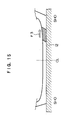
- a shear force (a direction of an arrow F3) in the tire width direction is applied to the tread at a time of being trailed (particularly between a one quarter point and three eighths), and the outer portion from a one quarter point of the tread 12 is shear deformed in the width direction so as to generate a slip with respect to the road surface, as shown by a cross sectional view in Fig. 15.
- a compression force (an arrow F2) is applied toward the tire equatorial plane CL near the center of the tread.
- Fig. 16 is a graph showing a tread surface shape position of a tire (tire size: 4000R57) at a time of trailing, in which a vertical axis indicates a radial position of the tread surface, and a horizontal axis indicates a position in a width direction of the tread surface (0 in the horizontal direction indicates a tire equatorial plane position).
- a pneumatic tire having a non-specified rotational direction and comprising rug grooves cutting across at least a land portion at a shoulder side of a tread portion at both sides in a tire width direction, wherein the number of the rug grooves is in a range of from 32 to 44 at each side in the tire width direction, a negative rate of a tread surface portion of the tread portion is a range of from 15 to 30 %, each of the rug grooves has a tapered groove portion wherein a groove width gradually becomes narrower such that a trapezoidal block portion having a short side at the shoulder side as seen from a tire tread surface side is formed between the rug grooves in a tire peripheral direction, and the tapered groove portion is formed such that a distance from a tread end extends beyond a one quarter point corresponding to one half of a length from the tread end to the tire equatorial plane.
- the tread end indicates an outermost ground portion in the tire width direction in the case that a pneumatic tire is installed to a standard rim defined in JATMA YEAR BOOK (Japan Automobile Tire Manufacturers Association Standard edited on 2002), 100 % of an air pressure (a maximum air pressure) corresponding to a maximum load capacity (bald face load in internal pressure-load capacity correspondence table) in an applied size and ply rating in JATMA YEAR BOOK is filled as an internal pressure, and the maximum load capacity is loaded.
- TRA standard and ETRTO standard is applied in a used place or a manufactured place
- the pneumatic tire depends on each of the standards.
- the tread surface portion corresponds to a portion pinched by tread ends at each side in the tire width direction in the tread portion.
- the rug groove has the tapered groove portion as mentioned above, the trapezoidal block portion having the short side at the shoulder side as seen from the tire tread surface side is formed. Accordingly, whichever direction the tire is rotated, the rug angle ⁇ of the trailing end near the one quarter point becomes 90 degrees or less, and therefore, it is possible to obtain the pneumatic tire which prevents the one-side biased abrasion from being generated.
- the number of the rug grooves mentioned above is less than 32 in at least one side in the tire width direction, a heat radiation effect is reduced, and a heat system failure tends to be generated, and accordingly, this structure is not preferable. Further, if the number of the rug grooves mentioned above is more than 44 in at least one side in the tire width direction, a rug rigidity becomes small, and an early abrasion is generated, and accordingly, this structure is not preferable.
- a negative rate of the tread surface portion of the tread portion is less than 15 %, the heat radiation effect is reduced, and the heat system failure tends to be generated and accordingly, this structure is not preferable, and if it is more than 30 %, the rug rigidity becomes small and the early abrasion is generated, and accordingly, this structure is not preferable.
- the tapered groove portion mentioned above is not formed so as to extend beyond the one quarter point mentioned above, all of the trapezoidal block portions are positioned at the outer side in the tire width direction, or all of the trapezoidal block portions are positioned closer to the tire equatorial plane side than the one quarter point mentioned above.
- the portion which is exposed to the curved deformation of the belt, generates the slip in the width direction and generates the abrasion (the biased abrasion) is a portion near the one quarter point, and accordingly, if the trapezoidal block portion does not rest on the one quarter point, the effect can not be obtained so much. Therefore, according to the invention described in the first aspect, the tapered groove portion is formed such that the distance from the tread end extends beyond the one quarter point corresponding to the one half of the length from the tread end to the tire equatorial plane.
- a pneumatic tire according to the first aspect, wherein the tread portion comprises a pair of peripheral narrow grooves, disposed one on either side of the tire equatorial plane, and a plurality of widthwise narrow grooves disposed at a tire equatorial plane side and spaced in the tire peripheral direction, a belt is disposed at an inner side in a tire diameter direction of the tread portion, the widthwise narrow grooves have a groove width that is choked when grounded, and the peripheral narrow grooves are disposed at an outer side in the tire width direction with respect to the one quarter point and at an inner side in the tire width direction with respect to an outermost end in the tire width direction of the belt, a groove depth is equal to or less than a groove depth of the rug groove, and a groove width is set in a range of from 1 to 2.5 % of the tread width.
- the peripheral narrow grooves set to the groove width choked when grounded is disposed at the outer side in the tire width direction with respect to the one quarter point which is one quarter of the tread width away from the tire equatorial plane to the outer side in the tire width direction, and at the inner side in the tire width direction with respect to the outermost end in the tire width direction of the belt, the peripheral narrow grooves obstructs the transmission of the influence of the shear deformation of the outer portion of the tread to the portion near the one quarter point. Accordingly, it is possible to suppress the motion of the tread surface to the outer side at the trailing time caused by the belt curved deformation near the one quarter point, and as a result, it is possible to improve the abrasion resistance near the one quarter point.
- the groove width of the widthwise narrow groove becomes less than 1 %, a durability of a mold frame (or a blade (a metal plate)) for forming the widthwise narrow groove is undesirably lowered.
- a pneumatic tire according to the first aspect or the second aspect wherein an auxiliary groove extending in the tire peripheral direction is provided in a tread center portion.
- a pneumatic tire according to the second aspect wherein an auxiliary groove extending in the tire peripheral direction is provided at a tread center portion, and a negative rate at an inner side of the pair of peripheral narrow grooves and within a range of a length corresponding to 1 pitch in the tire peripheral direction of the main rug groove is set in a range of from 15 to 30 %.
- a pneumatic tire according to the third aspect or the fourth aspect wherein a maximum depth of the auxiliary groove is between one eighth and one third of the depth of the main rug groove.
- the maximum depth of the auxiliary groove is less than one eighth of the groove depth of the main rug groove, the heat radiation of the heat generated in the block becomes insufficient.
- a pneumatic tire according to any one of the first aspect and the fifth aspect, wherein the tread surface of the trapezoidal block is formed in an isosceles trapezoidal shape.
- a pneumatic tire according to any one of the first aspect and the sixth aspect wherein an angle formed by an oblique line of the tread surface of the trapezoidal block portion and the tire width direction is from 10 degrees to 20 degrees.
- the angle formed by the oblique line of the tread surface of the trapezoidal block portion and the tire width direction is from 10 degrees to 20 degrees.
- the invention is structured as mentioned above, it is possible to achieve the pneumatic tire which is preferable for the construction vehicle and prevents the one-side biased abrasion from being generated.
- a pneumatic tire 10 for a construction wheel relating to the present embodiment is constituted by a pneumatic tire having a non-specified rotational direction (non-direction), and has a carcass 12 extending in a toroidal shape, a belt 14 provided at an outer side of a crown portion of the carcass 12, and a tread portion 16 provided at an outer side of the belt 14 and connected in the toroidal shape between side wall portions.
- the pneumatic tire 10 has rug grooves 20 (refer to Fig. 2) extending to the tread portion 16 from a shoulder portion 18 beyond a tread end T at each side in a tire width direction. At any side in the tire width direction, a number of the rug grooves 20 is set in a range of from 32 to 44. Further, a negative rate of a tread surface portion 17 of the tread portion 16 is within a range of from 15 to 30 %.
- the rug groove 20 has a tapered groove portion 21 in which a groove width gradually becomes narrower, such that a trapezoidal block portion 22 in which a short side is at a shoulder side as seen from a tire tread surface side is formed between the rug grooves 20 in a tire peripheral direction.
- the tapered groove portion 21 is formed so as to extend to a tire equatorial plane CL side beyond a one quarter point Q in which a distance from the tread end T is one half of a length from the tread end T to the tire equatorial plane CL.
- the tapered groove portion 21 is structured such that a direction is reversed and a dimension is identical between one side in the tire width direction (a left side of a paper surface than the tire equatorial plate CL in Fig. 2) and the other side in the tire width direction (a right side of the paper surface than the tire equatorial plane CL in Fig. 2).
- the tapered groove portion 21 is shifted at a position in a tire peripheral direction between the one side in the tire width direction and the other side in the tire width direction. As a result, a leading end of the tapered groove portion 21 is not positioned on the same line in the tire width direction between the one side in the tire width direction and the other side in the tire width direction.
- the position in the tire width direction of the tapered groove portion 21 is set such that the one quarter point Q is positioned at an approximately middle point of an oblique line of the trapezoidal block portion 22.
- the tapered groove portion 21 is formed in an isosceles triangular shape as seen from the tire tread surface side, and both of an angle (an acute angle) formed by an oblique line 19A at one side of the tapered groove portion 21 with respect to a tire width direction U, and an angle (an acute angle) formed by an oblique line 19B at the other side of the tapered groove portion 21 with respect to the tire width direction U are set to the same angle ⁇ .
- a tread surface 22S of the trapezoidal block portion 22 is formed in an isosceles trapezoidal shape.
- the angle ⁇ is 10 degrees or more and 20 degrees or less.
- the rug groove 20 has the tapered groove portion 21 mentioned above, there is formed the trapezoidal block portion 22 in which the short side is formed at the shoulder side as seen from the tire tread surface side. Accordingly, whichever direction the pneumatic tire 10 is rotated in, all of rug angles (angles formed by the trailing end with respect to the tire rotational direction) ⁇ of the trailing end near the one quarter point Q are identical and become less than 90 degrees. Accordingly, it is possible to achieve the pneumatic tire 10 for the construction vehicle which prevents the one-side biased abrasion from being generated.
- a position of the tapered groove portion 31 is different in comparison with the first embodiment.
- a tapered groove portion 31 is formed so as to stride over the one quarter point Q, and is formed at a position closer to the tire equatorial plane CL in comparison with the first embodiment.
- a trapezoidal block portion 32 formed in a tread surface portion 37 by the tapered groove portion 31 is formed at a position closer to the tire equatorial plane in comparison with the first embodiment.
- a dimension of the tapered groove portion 31 is the same as that of the tapered groove portion 21, and is formed in an isosceles triangular shape as seen from the tire tread surface side.
- the present embodiment it is possible to make a tire temperature at the tire equatorial plane CL side lower than the first embodiment. Further, since the trapezoidal block portion 32 is formed so as to stride over the one quarter point Q, it is possible to suppress the abrasion at the trailing side of the one quarter point Q.
- a tapered groove portion 41 is formed so as to stride over the one quarter point Q, and is formed at a position far from the tire equatorial plane CL, that is, a position closer to the tread end T, in comparison with the first embodiment.
- a trapezoidal block portion 42 formed in a tread surface portion 47 by the tapered groove portion 41 is formed at a position closer to the tread end T in comparison with the first embodiment.
- a dimension of the tapered groove portion 41 is the same as the tapered groove portion 21, and is formed in an isosceles triangular shape as seen from the tire tread surface side.
- the present embodiment it is possible to increase an abrasion resistance at the tire equatorial plane CL side than the first embodiment. Further, since the trapezoidal block portion 32 is formed so as to stride over the one quarter point Q, it is possible to suppress the abrasion at the trailing side of the one quarter point Q.
- a narrow groove 54 extending in the tire peripheral direction is provided in a tread surface portion 57, at an outer side in the tire width direction than the one quarter point Q in comparison with the second embodiment.
- a force deforming to an outer side in the tire width direction is applied to the land portion at the outer side in the tire width direction than the one quarter point Q, and a force deforming to an inner side in the tire width direction is applied to the land portion at the inner side in the tire width direction than the one quarter point Q.
- the present embodiment it is possible to widely reduce the deforming force to the outer side in the tire width direction exposed to the land portion formed so as to stride over the one quarter point Q. Therefore, it is possible to widely reduce an amount of abrasion of the trapezoidal block portion 52 formed so as to stride over the one quarter point Q.
- a center groove 56 extending in the tire peripheral direction is provided in a tread center portion 55.
- a connection groove 60 connecting the tapered groove portion 31 at the one side in the tire width direction and the tapered groove portion 31 at the other side in the tire width direction is formed in the tread surface portion 57.
- a center narrow groove surrounding type block pattern is formed in the tread surface portion 57, by the center groove 56, the narrow groove 54, the tapered groove portion 31 and the connection groove 60.
- the present embodiment it is possible to make the tire temperature at the tire equatorial plane CL side lower than the first embodiment. Further, since the trapezoidal block portion 32 is formed so as to stride over the one quarter point Q, it is possible to suppress the abrasion at the trailing side of the one quarter point Q.
- the inventors of the invention first execute a performance test by using a pneumatic tire (a pneumatic tire in the related art 1, refer to Fig. 6) in which a tire size is 4000R57, and a block portion 82 near the one quarter point Q as seen from the tire tread surface side is rectangular, as a conventional pneumatic tire for a construction vehicle.
- a pneumatic tire a pneumatic tire in the related art 1, refer to Fig. 6
- a tire size is 4000R57
- a block portion 82 near the one quarter point Q as seen from the tire tread surface side is rectangular
- a pitch number of rug grooves 80 of the pneumatic tire in the related art 1 is 36, and all of angles of the rug grooves 80 with respect to the tire width direction are 0 degree.
- a test condition is set such that a tire is attached to a front side of a 240 ton load dump truck, an abrasion resistance is measured after operating for one hundred days in a copper mine in the United States, and an index 100 is set as a reference value.
- a tire structure and the index are shown in Table 1.
- the inventors of the invention execute a performance test under the same condition by using a pneumatic tire (refer to Fig. 7) in the related art 2 in which a tire size is the same as the pneumatic tire in the related art 1 mentioned above, and a block portion 92 near the one quarter point Q as seen from the tire tread surface side is parallelogram.
- a pitch number of the rug grooves 90 of the pneumatic tire in the related art 2 is 36, and all of the angles ⁇ formed by the rug grooves 90 with respect to the tire width direction are 18 degrees.
- abrasion resistance is measured, and a performance index corresponding to a relative evaluation with respect to the pneumatic tire in the related art 1 is calculated.
- the tire structure and the calculated performance index of the pneumatic tire in the related art 2 are shown together in Table 1. In Table 1, there are shown a matter that the larger the performance index is, the better the performance is, and the lower the performance index is, the more inferior the performance is.
- the inventors of the invention execute the performance test under the same condition by using a pneumatic tire in the second embodiment (the pneumatic tire in the example 1) in which the tire size is identical to the pneumatic tire in the related art 1 mentioned above.
- the angle ⁇ formed by the oblique lines 29A and 19B of the tapered groove portion 31 with respect to the tire width direction is set to 11 degrees.
- the abrasion resistance is measured, and the performance index corresponding to the relative evaluation with respect to the pneumatic tire in the related art 1 is calculated.
- the tire structure of the pneumatic tire in the example 1 and the calculated performance index are shown together in Table 1.
- the inventors of the invention execute the performance test under the same condition by using a pneumatic tire in the third embodiment (the pneumatic tire in the example 2) in which the tire size is identical to the pneumatic tire in the related art 1 mentioned above.
- the angle ⁇ is set to 15 degrees.
- the abrasion resistance is measured, and the performance index corresponding to the relative evaluation with respect to the pneumatic tire in the related art 1 is calculated, in the same manner as the pneumatic tire in the example 1.
- the tire structure of the pneumatic tire in the example 2 and the calculated performance index are shown together in Table 1.
- peripheral narrow grooves 214 extending along the tire peripheral direction are formed at each side of the tire equatorial plane CL, in a tread 212 of a pneumatic tire 210 in the present embodiment.
- the pneumatic tire 210 in the present embodiment is provided for the construction vehicle, and a thickness of the tread 212 is 60 mm or more in a center portion.
- a belt 218 constituted by a plurality of belt plies is embedded between the tread 212 and a radial carcass 216.
- the peripheral narrow groove 214 is disposed at an outer side in a tire width direction than a one quarter point P 1 which is one quarter of a tread width TW away from the tire equatorial plane CL to an outer side in the tire width direction, and at an inner side in the tire width direction than an outermost end 218E in a tire width direction of the belt 218.
- a groove depth of the peripheral narrow groove 214 is set to be a groove depth or less of a main rug groove 220 mentioned below, and a groove width is set within a range of from 1 to 2.5 % of the tread width TW.
- a plurality of main rug grooves 220 extending toward the tire equatorial plane CL from a ground contact end 212E are formed in the tread 212 so as to be spaced in the tire peripheral direction.
- the main rug groove 220 is terminated at a position which is slightly beyond the one quarter point P 1 from the ground contact end 212E.
- the main rug groove 220 at a right side of the tire equatorial plane CL and the main rug groove 220 at a left side of the tire equatorial plane CL are disposed so as to be shifted in the tire peripheral direction.
- the groove width of the main rug groove 220 is set to a suitable dimension for arranging 32 to 44 main rug grooves 220 per one circle of the tread.
- the groove depth of the main rug groove 220 is smaller than a thickness of the tread 212, and is preferably 60 mm or more in the case of being measured at the ground contact end 212E of the tread 212.
- a widthwise narrow groove 222 connecting the main rug groove 220 at the right side and the main rug groove 220 at the left side is formed in the tread 212, and a block 224 is compartmented by the peripheral narrow groove 214 and the widthwise narrow groove 222 in a center region of the tread 212, between a pair of peripheral narrow grooves 214 in the present embodiment.
- the groove width of the peripheral narrow groove 214 is set so as to be choked at a time of being grounded on the road surface at a time of load rolling.
- An auxiliary groove 226 extending along the tire peripheral direction is formed in the center (on the tire equatorial plane CL) in the tire width direction of the block 224.
- a maximum depth of the auxiliary groove 226 is set between one eighth and one third of the groove depth of the main rug groove 220.
- a negative rate at the inner side of a pair of peripheral narrow grooves 214, and within the region of the length L1 corresponding to one pitch of the main rug groove 220 in the tire peripheral direction is set within a range of from 15 to 30 %.
- auxiliary groove 226 is formed in the block 224 being compartmented by the center portion of the tread 212, it is possible to radiate the heat generated from the block 224 due to the load rolling from the auxiliary groove 226, and it is possible to intend to improve a heat generation resistance.
- the groove width of the widthwise narrow groove 222 becomes less than 1 % of the tread width TW, a durability of a mold frame (or a blade (a metal plate)) for forming the widthwise narrow groove 222 is undesirably lowered.
- the motion of the tread 212 becomes enlarged at a time of load rolling, and causes the abrasion.
- the maximum depth of the auxiliary groove 226 is less than one eighth of the groove depth of the main rug groove 220, the heat radiation of the heat generated in the block 224 becomes insufficient.
- the motion of the tread 212 becomes enlarged at a time of load rolling, and causes a deterioration of the abrasion resistance.
- the widthwise narrow groove 222 in the present embodiment is formed in the linear shape, however, the present invention is not limited to this, but may be formed in a zigzag shape or the like.
- an abrasion resistance index is compared by preparing the pneumatic tire in a related art example and the pneumatic tire in an example to which the invention is applied.
- tire size 4000R57 rim: 29 inch diameter x 6 inch flange height internal pressure: 700 kPa load: TRA standard 100% Load (60 ton)
- An evaluation is executed by an index display by setting an inverse number of an amount of motion of the related art to 100, and indicates that the greater the numerical value is, the more excellent the abrasion resistance is.
- Example Related art example Tread width 980mm 980mm Tread layer gauge (tire equatorial plane) 110mm 110mm Main rug groove average depth 90mm 90mm Peripheral narrow groove depth 30mm 30mm Distance of peripheral narrow groove from tire equatorial plane (measured in center of amplitude in case of zigzag) 290 mm (near a one quarter point) 145mm (near a one eighth point) With or without auxiliary groove With Without Tread surface average moving amount at a time of leading and trailing (position of a one quarter point) 2.0mm 2.5mm Abrasion resistance index (INDEX) 125 100
- the one eighth point in the table indicates a position which is one eighth of the tread width away from the tire equatorial plane toward the tread end.
- the pneumatic tire in the present example to which the invention is applied has a less motion at the one quarter point of the tread than the pneumatic tire in the related art example, and is excellent in the abrasion resistance at the one quarter point.
- the pneumatic tire in the present invention can be applied to an intended use for traveling on a rough road by the construction vehicle or the like.
Landscapes
- Engineering & Computer Science (AREA)
- Mechanical Engineering (AREA)
- Tires In General (AREA)
Abstract
Description
- The present invention relates to an off-road pneumatic tire in which a rotating direction is not specified.
- In a construction vehicle, there has been widely used a heavy load tire for a construction vehicle in which a rotating direction is not specified (a non-directional property is provided) (for example, refer to patent document 1).
- A non-directional rug pattern is formed on a tread surface of the heavy load tire for the construction vehicle mentioned above. For example, as shown in Fig. 6,
rug grooves 80 are formed on atread surface portion 87 of atread portion 86 of the heavy load tire for the construction vehicle according to arelated art 1, at a predetermined interval in the same direction as a tire width direction. - In recent years, in the heavy load tire for the construction vehicle mentioned above, it becomes a mainstream to attach a predetermined angle to a rug groove of the rug pattern, for securing an edge component in a width direction, securing a heat radiation performance, and solving a vibration problem. For example, as shown in Fig. 7, in a pneumatic tire according to a related art 2,
rug grooves 90 of atread surface portion 97 are formed so as to be in parallel to each other at an angle θ with respect to a tire width direction. - However, in the case that the
rug groove 90 inclined with respect to a tire width direction U, such as the heavy load tire for the construction vehicle according to the related art 2, there is a problem that therug groove 90 wears at an early stage only in aland portion 93 at one side of thelug groove 90 near a quarter point Q at which a distance from a tread end T is one half of a length from the tread end T to a tire equatorial plane, and a one-side biased abrasion is generated (refer to Figs. 8 and 9). - In this case, since an input of a side force is large in the case that the heavy load tire for the construction vehicle is installed to a front side, this matter particularly remarkably appears.
- Further, as a technique of suppressing the biased abrasion of the tread so as to improve a tire life (an abrasion resistance), there is a technique, for example, disclosed in patent document 2. This is structured such as to increase a rigidity at a shoulder side and suppress a biased abrasion at a shoulder side by arranging a lot of volume of a tread rubber close to the shoulder rather than the tread pattern of the conventional tire. However, according to this related art, a certain degree of improvement of the abrasion resistance appears, however, there is a demand of further improving the abrasion resistance near an intermediate portion between the tire equatorial plane and a ground contact end of the tread, so-called one quarter point, in a market.
- Patent Document 1: Japanese Patent Application Laid-Open (
JP-A) No. 2000-233610 - Patent Document 2: Japanese Patent Application Laid-Open (
JP-A) No. 2001-225608 - The present invention is made by taking the fact mentioned above into consideration, and an object of the invention is to provide a pneumatic tire which prevents a one-side biased abrasion from being generated in comparison with the conventional structure.
- The inventors of the invention have made a study of a reason why the one-side biased abrasion is generated. Then, the inventors have executed an analyzing calculation, and have found the following matter.
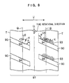
- In the heavy load tire for the construction vehicle, since a lot of belt layers are laminated, a curved deformation is generated in a tire width direction within the tread surface at a time of being loaded. As a result, the land portion near the one quarter point is deformed so as to slide to an outer side in the tire width direction at a time of trailing. Accordingly, in the pneumatic tire according to the related art 2, as shown in Fig. 8, the land portion near the one quarter point Q is deformed so as to slide to an outer side UE in the tire width direction at a time of trailing from the tread surface.
- On the other hand, a
rug groove 90 is sloped at the same angle in the same direction with respect to a tire width direction U. Accordingly, a rug angle (an angle formed by the rug groove with respect to the tire rotational direction) α of atrailing end 94 near the one quarter point Q is different from each other in both sides of a tire equatorial plane CL, in correspondence to a rotational direction of the tire. If the rotational direction is set to a positive axis, a relation α > 90 degrees is established at a right side of a paper surface from the tire equatorial plane CL in Fig. 8, and a relation α > 90 degrees is established at a left side of the paper surface from the tire equatorial plane CL. - In this case, the
trailing end 94 is exposed to a force of sliding in a direction K orthogonal to the trailingend 94, at a time of trailing. - Accordingly, in the case that the relation α > 90 degrees is established, the
trailing end 94 is exposed to a force of further sliding to the outer side UE in the tire width direction. Therefore, an abrasion of thetrailing end 94 is further promoted. - On the other hand, in the case that the relation α < 90 degrees is established, the
trailing end 94 is exposed to a force of deforming to an inner side in the tire width direction. Therefore, the abrasion of the trailingend 94 is suppressed. - On the basis of the principle mentioned above, the rug groove wears at an early stage only in the
land portion 93 at one side of the rug groove. - As shown in Fig. 9, even in the case that the rotational direction of the tire is set reverse, the
rug groove 90 wears at an early stage only in the land portion at one side of therug groove 90 on the basis of the same principle. - Accordingly, the inventors of the invention have made a study of the structure for making the rug angle α at the trailing side near the one
quarter point 90 degrees or less whichever directions the tire is rotated, have made repeated experiments, and have completed the invention. - Further, viewing the deformation of a whole of the tire by a cross sectional view, the tread surface which is flat just under the load (illustrated by a two-dot chain line) is deformed such that the portion near the tire equatorial plane CL is concaved, at a time of leading or trailing (before and after being grounded on a road surface or before and after being away from the road surface, illustrated by a solid line), as shown in Fig. 14. As a result, there has been known that a motion of the tread surface to the outer side in the width direction becomes enlarged by a force (an arrow F1) of pulling to an outer side in a direction of a curved deformation of a belt, at a time when the tire is rolled and trailed, near the one quarter point of the tread, and the abrasion resistance is deteriorated. In other words, a shear force (a direction of an arrow F3) in the tire width direction is applied to the tread at a time of being trailed (particularly between a one quarter point and three eighths), and the outer portion from a one quarter point of the
tread 12 is shear deformed in the width direction so as to generate a slip with respect to the road surface, as shown by a cross sectional view in Fig. 15. - In this connection, a compression force (an arrow F2) is applied toward the tire equatorial plane CL near the center of the tread.
- Fig. 16 is a graph showing a tread surface shape position of a tire (tire size: 4000R57) at a time of trailing, in which a vertical axis indicates a radial position of the tread surface, and a horizontal axis indicates a position in a width direction of the tread surface (0 in the horizontal direction indicates a tire equatorial plane position).
- According to a first aspect of the invention, there is provided a pneumatic tire having a non-specified rotational direction and comprising rug grooves cutting across at least a land portion at a shoulder side of a tread portion at both sides in a tire width direction, wherein the number of the rug grooves is in a range of from 32 to 44 at each side in the tire width direction, a negative rate of a tread surface portion of the tread portion is a range of from 15 to 30 %, each of the rug grooves has a tapered groove portion wherein a groove width gradually becomes narrower such that a trapezoidal block portion having a short side at the shoulder side as seen from a tire tread surface side is formed between the rug grooves in a tire peripheral direction, and the tapered groove portion is formed such that a distance from a tread end extends beyond a one quarter point corresponding to one half of a length from the tread end to the tire equatorial plane.
- The tread end indicates an outermost ground portion in the tire width direction in the case that a pneumatic tire is installed to a standard rim defined in JATMA YEAR BOOK (Japan Automobile Tire Manufacturers Association Standard edited on 2002), 100 % of an air pressure (a maximum air pressure) corresponding to a maximum load capacity (bald face load in internal pressure-load capacity correspondence table) in an applied size and ply rating in JATMA YEAR BOOK is filled as an internal pressure, and the maximum load capacity is loaded. In the case that TRA standard and ETRTO standard is applied in a used place or a manufactured place, the pneumatic tire depends on each of the standards. The tread surface portion corresponds to a portion pinched by tread ends at each side in the tire width direction in the tread portion.
- According to the invention of the first aspect, since the rug groove has the tapered groove portion as mentioned above, the trapezoidal block portion having the short side at the shoulder side as seen from the tire tread surface side is formed. Accordingly, whichever direction the tire is rotated, the rug angle α of the trailing end near the one quarter point becomes 90 degrees or less, and therefore, it is possible to obtain the pneumatic tire which prevents the one-side biased abrasion from being generated.
- If the number of the rug grooves mentioned above is less than 32 in at least one side in the tire width direction, a heat radiation effect is reduced, and a heat system failure tends to be generated, and accordingly, this structure is not preferable. Further, if the number of the rug grooves mentioned above is more than 44 in at least one side in the tire width direction, a rug rigidity becomes small, and an early abrasion is generated, and accordingly, this structure is not preferable.
- Further, if a negative rate of the tread surface portion of the tread portion is less than 15 %, the heat radiation effect is reduced, and the heat system failure tends to be generated and accordingly, this structure is not preferable, and if it is more than 30 %, the rug rigidity becomes small and the early abrasion is generated, and accordingly, this structure is not preferable.
- Further, if the tapered groove portion mentioned above is not formed so as to extend beyond the one quarter point mentioned above, all of the trapezoidal block portions are positioned at the outer side in the tire width direction, or all of the trapezoidal block portions are positioned closer to the tire equatorial plane side than the one quarter point mentioned above. In this case, the portion which is exposed to the curved deformation of the belt, generates the slip in the width direction and generates the abrasion (the biased abrasion) is a portion near the one quarter point, and accordingly, if the trapezoidal block portion does not rest on the one quarter point, the effect can not be obtained so much. Therefore, according to the invention described in the first aspect, the tapered groove portion is formed such that the distance from the tread end extends beyond the one quarter point corresponding to the one half of the length from the tread end to the tire equatorial plane.
- According to a second aspect of the invention, there is provided a pneumatic tire according to the first aspect, wherein the tread portion comprises a pair of peripheral narrow grooves, disposed one on either side of the tire equatorial plane, and a plurality of widthwise narrow grooves disposed at a tire equatorial plane side and spaced in the tire peripheral direction, a belt is disposed at an inner side in a tire diameter direction of the tread portion, the widthwise narrow grooves have a groove width that is choked when grounded, and the peripheral narrow grooves are disposed at an outer side in the tire width direction with respect to the one quarter point and at an inner side in the tire width direction with respect to an outermost end in the tire width direction of the belt, a groove depth is equal to or less than a groove depth of the rug groove, and a groove width is set in a range of from 1 to 2.5 % of the tread width.
- According to the pneumatic tire of the second aspect, since the peripheral narrow grooves set to the groove width choked when grounded is disposed at the outer side in the tire width direction with respect to the one quarter point which is one quarter of the tread width away from the tire equatorial plane to the outer side in the tire width direction, and at the inner side in the tire width direction with respect to the outermost end in the tire width direction of the belt, the peripheral narrow grooves obstructs the transmission of the influence of the shear deformation of the outer portion of the tread to the portion near the one quarter point. Accordingly, it is possible to suppress the motion of the tread surface to the outer side at the trailing time caused by the belt curved deformation near the one quarter point, and as a result, it is possible to improve the abrasion resistance near the one quarter point.
- In this case, if the groove width of the widthwise narrow groove becomes less than 1 %, a durability of a mold frame (or a blade (a metal plate)) for forming the widthwise narrow groove is undesirably lowered.
- On the other hand, if the groove width of the widthwise narrow groove gets over 2.5 % of the tread width, the motion of the tread becomes large, and causes the abrasion.
- In this case, "when grounded" of the groove width that is choked when grounded means at when the tread is grounded on the road surface.
- According to a third aspect of the invention, there is provided a pneumatic tire according to the first aspect or the second aspect, wherein an auxiliary groove extending in the tire peripheral direction is provided in a tread center portion.
- Accordingly, it is possible to easily form the trapezoidal block portion striding beyond the one quarter point. Therefore, it is easy to suppress the abrasion at the trailing side of the one quarter point. Further, it is possible to radiate the heat generated from the block of the tread center portion via the auxiliary groove, by forming the auxiliary groove in the tread center portion.
- According to a fourth aspect of the invention, there is provided a pneumatic tire according to the second aspect, wherein an auxiliary groove extending in the tire peripheral direction is provided at a tread center portion, and a negative rate at an inner side of the pair of peripheral narrow grooves and within a range of a length corresponding to 1 pitch in the tire peripheral direction of the main rug groove is set in a range of from 15 to 30 %.
- It is possible to radiate the heat generated from the block of the tread center portion via the auxiliary groove, by forming the auxiliary groove in the tread center portion.
- In this case, if the negative rate at the inner side of the pair of peripheral narrow groves of the tread and within the range of the length corresponding to 1 pitch in the tire peripheral direction of the main rug groove becomes less than 15 %, it is impossible to sufficiently radiate the heat of the tread under the use in the market. On the other hand, if the negative rate gets over 30 %, a stone biting performance in the tread center portion is deteriorated, and the grooves tend to bite the stone at a time of traveling on a punishing road.
- According to a fifth aspect of the invention, there is provided a pneumatic tire according to the third aspect or the fourth aspect, wherein a maximum depth of the auxiliary groove is between one eighth and one third of the depth of the main rug groove.
- If the maximum depth of the auxiliary groove is less than one eighth of the groove depth of the main rug groove, the heat radiation of the heat generated in the block becomes insufficient.
- If the maximum depth of the auxiliary groove gets over one third of the groove depth of the main rug groove, the motion of the tread becomes enlarged, and causes a deterioration of the abrasion resistance.
- According to a sixth aspect of the invention, there is provided a pneumatic tire according to any one of the first aspect and the fifth aspect, wherein the tread surface of the trapezoidal block is formed in an isosceles trapezoidal shape.
- Accordingly, in the case of attaching the pneumatic tire to the construction vehicle and repeating a forward movement and a backward movement at the same degree, a position near an oblique line of the trapezoidal block portion wears at the same degree. Therefore, a tire service life becomes elongated.
- According to a seventh aspect of the invention, there is provided a pneumatic tire according to any one of the first aspect and the sixth aspect, wherein an angle formed by an oblique line of the tread surface of the trapezoidal block portion and the tire width direction is from 10 degrees to 20 degrees.
- Since the higher the angle formed by the oblique line of the tread surface of the trapezoidal block portion and the tire width direction is, the higher the effect of suppressing the slip in the width direction is, it is preferable that the angle is 10 degrees or more. However, if the angle is made 20 degrees or more, the groove shape becomes extremely thick, and accordingly, this structure is not preferable. Then, according to the third aspect of the invention, the angle formed by the oblique line of the tread surface of the trapezoidal block portion and the tire width direction is from 10 degrees to 20 degrees.
- Accordingly, it is possible to properly increase the effect of suppressing the slip in the width direction.
- Since the invention is structured as mentioned above, it is possible to achieve the pneumatic tire which is preferable for the construction vehicle and prevents the one-side biased abrasion from being generated.
-
- Fig. 1 is a cross sectional view in a tire diametrical direction showing a structure of a pneumatic tire relating to a first embodiment;
- Fig. 2 is a partly plan view showing a rug groove pattern within a tread width in the pneumatic tire relating to the first embodiment;
- Fig. 3 is a partly plan view showing a rug groove pattern within a tread width in a pneumatic tire relating to a second embodiment;
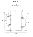
- Fig. 4 is a partly plan view showing a rug groove pattern within a tread width in a pneumatic tire relating to a third embodiment;
- Fig. 5 is a partly plan view showing a rug groove pattern within a tread width in a pneumatic tire relating to a fourth embodiment;
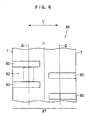
- Fig. 6 is a partly plan view showing a rug groove pattern within a tread width in a conventional pneumatic tire;
- Fig. 7 is a partly plan view showing a rug groove pattern within a tread width in a conventional pneumatic tire;
- Fig. 8 is a partly plan view showing a fact that a land portion at a trailing side of a rug groove tends to wear, in the conventional pneumatic tire;
- Fig. 9 is a partly plan view showing a fact that a land portion at a trailing side of a rug groove tends to wear, in the conventional pneumatic tire;
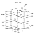
- Fig. 10 is a plan view of a tread of a pneumatic tire relating to a fifth embodiment;
- Fig. 11 is a cross sectional view showing a part of the pneumatic tire relating to the fifth embodiment;
- Fig. 12 is an enlarged plan view of a center portion of the tread shown in Fig. 10;
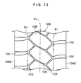
- Fig. 13 is a plan view of a tread of a pneumatic tire relating to a related art used in a test;
- Fig. 14 is an explanatory view showing a deformation of the tire;
- Fig. 15 is a cross sectional view showing a deformation of the tread; and
- Fig. 16 is a graph showing a curved state of a tread surface.
- A description will be given below of modes for carrying out the invention by giving embodiments.
- A description will be first given of a first embodiment. As shown in Fig. 1, a
pneumatic tire 10 for a construction wheel relating to the present embodiment is constituted by a pneumatic tire having a non-specified rotational direction (non-direction), and has acarcass 12 extending in a toroidal shape, abelt 14 provided at an outer side of a crown portion of thecarcass 12, and atread portion 16 provided at an outer side of thebelt 14 and connected in the toroidal shape between side wall portions. - The
pneumatic tire 10 has rug grooves 20 (refer to Fig. 2) extending to thetread portion 16 from ashoulder portion 18 beyond a tread end T at each side in a tire width direction. At any side in the tire width direction, a number of therug grooves 20 is set in a range of from 32 to 44. Further, a negative rate of atread surface portion 17 of thetread portion 16 is within a range of from 15 to 30 %. - Further, the
rug groove 20 has a taperedgroove portion 21 in which a groove width gradually becomes narrower, such that atrapezoidal block portion 22 in which a short side is at a shoulder side as seen from a tire tread surface side is formed between therug grooves 20 in a tire peripheral direction. The taperedgroove portion 21 is formed so as to extend to a tire equatorial plane CL side beyond a one quarter point Q in which a distance from the tread end T is one half of a length from the tread end T to the tire equatorial plane CL. - In the present embodiment, the tapered
groove portion 21 is structured such that a direction is reversed and a dimension is identical between one side in the tire width direction (a left side of a paper surface than the tire equatorial plate CL in Fig. 2) and the other side in the tire width direction (a right side of the paper surface than the tire equatorial plane CL in Fig. 2). - The tapered
groove portion 21 is shifted at a position in a tire peripheral direction between the one side in the tire width direction and the other side in the tire width direction. As a result, a leading end of the taperedgroove portion 21 is not positioned on the same line in the tire width direction between the one side in the tire width direction and the other side in the tire width direction. - Further, in the present embodiment, the position in the tire width direction of the tapered
groove portion 21 is set such that the one quarter point Q is positioned at an approximately middle point of an oblique line of thetrapezoidal block portion 22. - The tapered
groove portion 21 is formed in an isosceles triangular shape as seen from the tire tread surface side, and both of an angle (an acute angle) formed by an oblique line 19A at one side of the taperedgroove portion 21 with respect to a tire width direction U, and an angle (an acute angle) formed by anoblique line 19B at the other side of the taperedgroove portion 21 with respect to the tire width direction U are set to the same angle θ. As a result, atread surface 22S of thetrapezoidal block portion 22 is formed in an isosceles trapezoidal shape. In the present embodiment, the angle θ is 10 degrees or more and 20 degrees or less. - As described above, according to the present embodiment, since the
rug groove 20 has the taperedgroove portion 21 mentioned above, there is formed thetrapezoidal block portion 22 in which the short side is formed at the shoulder side as seen from the tire tread surface side. Accordingly, whichever direction thepneumatic tire 10 is rotated in, all of rug angles (angles formed by the trailing end with respect to the tire rotational direction) α of the trailing end near the one quarter point Q are identical and become less than 90 degrees. Accordingly, it is possible to achieve thepneumatic tire 10 for the construction vehicle which prevents the one-side biased abrasion from being generated. - Next, a description will be given of a second embodiment. As shown in Fig. 3, in a pneumatic tire relating to the present embodiment, a position of the tapered
groove portion 31 is different in comparison with the first embodiment. - A tapered
groove portion 31 is formed so as to stride over the one quarter point Q, and is formed at a position closer to the tire equatorial plane CL in comparison with the first embodiment. As a result, atrapezoidal block portion 32 formed in atread surface portion 37 by the taperedgroove portion 31 is formed at a position closer to the tire equatorial plane in comparison with the first embodiment. A dimension of the taperedgroove portion 31 is the same as that of the taperedgroove portion 21, and is formed in an isosceles triangular shape as seen from the tire tread surface side. - According to the present embodiment, it is possible to make a tire temperature at the tire equatorial plane CL side lower than the first embodiment. Further, since the
trapezoidal block portion 32 is formed so as to stride over the one quarter point Q, it is possible to suppress the abrasion at the trailing side of the one quarter point Q. - Next, a description will be given of a third embodiment. As shown in Fig. 4, in a pneumatic tire relating to the present embodiment, a tapered
groove portion 41 is formed so as to stride over the one quarter point Q, and is formed at a position far from the tire equatorial plane CL, that is, a position closer to the tread end T, in comparison with the first embodiment. As a result, atrapezoidal block portion 42 formed in atread surface portion 47 by the taperedgroove portion 41 is formed at a position closer to the tread end T in comparison with the first embodiment. A dimension of the taperedgroove portion 41 is the same as the taperedgroove portion 21, and is formed in an isosceles triangular shape as seen from the tire tread surface side. - According to the present embodiment, it is possible to increase an abrasion resistance at the tire equatorial plane CL side than the first embodiment. Further, since the
trapezoidal block portion 32 is formed so as to stride over the one quarter point Q, it is possible to suppress the abrasion at the trailing side of the one quarter point Q. - Next, a description will be given of a fourth embodiment. As shown in Fig. 5, in a pneumatic tire relating to the present embodiment, a
narrow groove 54 extending in the tire peripheral direction is provided in atread surface portion 57, at an outer side in the tire width direction than the one quarter point Q in comparison with the second embodiment. - At a time of traveling, in the
tread surface portion 57, a force deforming to an outer side in the tire width direction is applied to the land portion at the outer side in the tire width direction than the one quarter point Q, and a force deforming to an inner side in the tire width direction is applied to the land portion at the inner side in the tire width direction than the one quarter point Q. - Accordingly, according to the present embodiment, it is possible to widely reduce the deforming force to the outer side in the tire width direction exposed to the land portion formed so as to stride over the one quarter point Q. Therefore, it is possible to widely reduce an amount of abrasion of the
trapezoidal block portion 52 formed so as to stride over the one quarter point Q. - Further, in the present embodiment, a
center groove 56 extending in the tire peripheral direction is provided in atread center portion 55. Further, aconnection groove 60 connecting the taperedgroove portion 31 at the one side in the tire width direction and the taperedgroove portion 31 at the other side in the tire width direction is formed in thetread surface portion 57. As a result, a center narrow groove surrounding type block pattern is formed in thetread surface portion 57, by thecenter groove 56, thenarrow groove 54, the taperedgroove portion 31 and theconnection groove 60. - According to the present embodiment, it is possible to make the tire temperature at the tire equatorial plane CL side lower than the first embodiment. Further, since the
trapezoidal block portion 32 is formed so as to stride over the one quarter point Q, it is possible to suppress the abrasion at the trailing side of the one quarter point Q. - The inventors of the invention first execute a performance test by using a pneumatic tire (a pneumatic tire in the
related art 1, refer to Fig. 6) in which a tire size is 4000R57, and ablock portion 82 near the one quarter point Q as seen from the tire tread surface side is rectangular, as a conventional pneumatic tire for a construction vehicle. - In the present test example, a pitch number of
rug grooves 80 of the pneumatic tire in therelated art 1 is 36, and all of angles of therug grooves 80 with respect to the tire width direction are 0 degree. - A test condition is set such that a tire is attached to a front side of a 240 ton load dump truck, an abrasion resistance is measured after operating for one hundred days in a copper mine in the United States, and an
index 100 is set as a reference value. A tire structure and the index are shown in Table 1. -

- Further, the inventors of the invention execute a performance test under the same condition by using a pneumatic tire (refer to Fig. 7) in the related art 2 in which a tire size is the same as the pneumatic tire in the
related art 1 mentioned above, and ablock portion 92 near the one quarter point Q as seen from the tire tread surface side is parallelogram. - In the present test example, a pitch number of the
rug grooves 90 of the pneumatic tire in the related art 2 is 36, and all of the angles θ formed by therug grooves 90 with respect to the tire width direction are 18 degrees. - Further, the abrasion resistance is measured, and a performance index corresponding to a relative evaluation with respect to the pneumatic tire in the
related art 1 is calculated. The tire structure and the calculated performance index of the pneumatic tire in the related art 2 are shown together in Table 1. In Table 1, there are shown a matter that the larger the performance index is, the better the performance is, and the lower the performance index is, the more inferior the performance is. - Further, the inventors of the invention execute the performance test under the same condition by using a pneumatic tire in the second embodiment (the pneumatic tire in the example 1) in which the tire size is identical to the pneumatic tire in the
related art 1 mentioned above. In the pneumatic tire in the example 1, the angle θ formed by theoblique lines groove portion 31 with respect to the tire width direction is set to 11 degrees. Further, the abrasion resistance is measured, and the performance index corresponding to the relative evaluation with respect to the pneumatic tire in therelated art 1 is calculated. The tire structure of the pneumatic tire in the example 1 and the calculated performance index are shown together in Table 1. - Further, the inventors of the invention execute the performance test under the same condition by using a pneumatic tire in the third embodiment (the pneumatic tire in the example 2) in which the tire size is identical to the pneumatic tire in the
related art 1 mentioned above. In the pneumatic tire in the example 2, the angle θ is set to 15 degrees. Further, the abrasion resistance is measured, and the performance index corresponding to the relative evaluation with respect to the pneumatic tire in therelated art 1 is calculated, in the same manner as the pneumatic tire in the example 1. The tire structure of the pneumatic tire in the example 2 and the calculated performance index are shown together in Table 1. - As is understood from Table 1, there is obtained a result that in comparison with the pneumatic tire in the
related art 1, the abrasion resistance is widely improved in the pneumatic tire in the example 1, and is further improved in the pneumatic tire in the example 2. In this case, in the pneumatic tire in the related art 2, there is obtained a result that the performance is inferior to the pneumatic tire in therelated art 1. - The description is given of the modes for carrying out the invention by giving the embodiments, however, these embodiments are given as examples, and can be variously modified within a range within the scope of the invention. Further, it goes without saying that the claimed region of the invention is not limited to the embodiments mentioned above.
- As shown in Fig. 10, peripheral
narrow grooves 214 extending along the tire peripheral direction are formed at each side of the tire equatorial plane CL, in atread 212 of apneumatic tire 210 in the present embodiment. - The
pneumatic tire 210 in the present embodiment is provided for the construction vehicle, and a thickness of thetread 212 is 60 mm or more in a center portion. - As shown in Fig. 11, in this
pneumatic tire 210, abelt 218 constituted by a plurality of belt plies is embedded between thetread 212 and aradial carcass 216. - The peripheral
narrow groove 214 is disposed at an outer side in a tire width direction than a onequarter point P 1 which is one quarter of a tread width TW away from the tire equatorial plane CL to an outer side in the tire width direction, and at an inner side in the tire width direction than anoutermost end 218E in a tire width direction of thebelt 218. - A groove depth of the peripheral
narrow groove 214 is set to be a groove depth or less of amain rug groove 220 mentioned below, and a groove width is set within a range of from 1 to 2.5 % of the tread width TW. - A plurality of
main rug grooves 220 extending toward the tire equatorial plane CL from aground contact end 212E are formed in thetread 212 so as to be spaced in the tire peripheral direction. - The
main rug groove 220 is terminated at a position which is slightly beyond the onequarter point P 1 from theground contact end 212E. - The
main rug groove 220 at a right side of the tire equatorial plane CL and themain rug groove 220 at a left side of the tire equatorial plane CL are disposed so as to be shifted in the tire peripheral direction. - It is preferable that the groove width of the
main rug groove 220 is set to a suitable dimension for arranging 32 to 44main rug grooves 220 per one circle of the tread. - Further, the groove depth of the
main rug groove 220 is smaller than a thickness of thetread 212, and is preferably 60 mm or more in the case of being measured at theground contact end 212E of thetread 212. - As shown in Fig. 10, a widthwise
narrow groove 222 connecting themain rug groove 220 at the right side and themain rug groove 220 at the left side is formed in thetread 212, and ablock 224 is compartmented by the peripheralnarrow groove 214 and the widthwisenarrow groove 222 in a center region of thetread 212, between a pair of peripheralnarrow grooves 214 in the present embodiment. - The groove width of the peripheral
narrow groove 214 is set so as to be choked at a time of being grounded on the road surface at a time of load rolling. - An
auxiliary groove 226 extending along the tire peripheral direction is formed in the center (on the tire equatorial plane CL) in the tire width direction of theblock 224. - Further, it is preferable that a maximum depth of the
auxiliary groove 226 is set between one eighth and one third of the groove depth of themain rug groove 220. - As shown in Fig. 12, it is preferable that a negative rate at the inner side of a pair of peripheral
narrow grooves 214, and within the region of the length L1 corresponding to one pitch of themain rug groove 220 in the tire peripheral direction (for example, a region surrounded by a two-dot chain line in the drawing) is set within a range of from 15 to 30 %. (operation)
Next, a description will be given of an operation of thepneumatic tire 210 according to the present embodiment. - In the
pneumatic tire 210 in the present embodiment, since a pair of peripheralnarrow grooves 214 set to the grove width which is choked at a time of being grounded are disposed at the outer side in the tire width direction than the one quarter point P1, and at the inner side in the tire width direction than the tire widthwiseoutermost end 218E, it is possible to suppress the motion of the tread surface to the outer side at a time of being trailed due to the belt curved deformation, near the one quarter point P1. As a result, it is possible to improve the abrasion resistance of thetread 212 near the one quarter point P1. - Further, since the
auxiliary groove 226 is formed in theblock 224 being compartmented by the center portion of thetread 212, it is possible to radiate the heat generated from theblock 224 due to the load rolling from theauxiliary groove 226, and it is possible to intend to improve a heat generation resistance. - In this case, if the negative rate within a pair of peripheral
narrow grooves 214 of thetread 212 and within the region of the length corresponding to one pitch of themain rug groove 220 in the tire peripheral direction becomes less than 15 %, it is impossible to sufficiently radiate the heat of thetread 212 under the use in the market. - On the other hand, if the negative rate gets over 30 %, a stone biting characteristic in the center portion of the
tread 212 is deteriorated, and the groove tends to bite a stone at a time of traveling on the punishing road. - Further, if the groove width of the widthwise
narrow groove 222 becomes less than 1 % of the tread width TW, a durability of a mold frame (or a blade (a metal plate)) for forming the widthwisenarrow groove 222 is undesirably lowered. - On the other hand, if the groove width of the widthwise
narrow groove 222 gets over 2.5 % of the tread width TW, the motion of thetread 212 becomes enlarged at a time of load rolling, and causes the abrasion. - If the maximum depth of the
auxiliary groove 226 is less than one eighth of the groove depth of themain rug groove 220, the heat radiation of the heat generated in theblock 224 becomes insufficient. - On the other hand, if the maximum depth of the
auxiliary groove 226 gets over one third of the groove depth of themain rug groove 220, the motion of thetread 212 becomes enlarged at a time of load rolling, and causes a deterioration of the abrasion resistance. - In this case, the widthwise
narrow groove 222 in the present embodiment is formed in the linear shape, however, the present invention is not limited to this, but may be formed in a zigzag shape or the like. - In the present embodiment, the description is given of the example in which the invention is applied to the pneumatic tire for the construction vehicle, however, it goes without saying that the invention can be applied to the tires for the other vehicles than the construction vehicle.
- In order to confirm the effect of the invention, an abrasion resistance index is compared by preparing the pneumatic tire in a related art example and the pneumatic tire in an example to which the invention is applied.
- Example: structure in the fifth embodiment mentioned above
- Related art example: structure provided with a
main rug groove 100, peripheralnarrow grooves 102 extending in a zigzag shape in the tire peripheral direction and connected to themain rug groove 100, and a widthwise narrow groove 104 connecting the right and left peripheralnarrow grooves 102, and in which ablock 108 is compartmented in a center of atread 106 by the peripheralnarrow grooves 102 and the widthwise narrow groove 104, as shown in Fig. 13. Note that a groove corresponding to the auxiliary groove in the example is not formed in theblock 108. Further, in Fig. 13,reference symbol P 1 denotes a one quarter point, andreference symbol 106E denotes a tread end. In this case, an internal structure of the tire is the same structure as the example. - tire size: 4000R57
rim: 29 inch diameter x 6 inch flange height
internal pressure: 700 kPa
load: TRA standard 100% Load (60 ton)
The tire is rolled under the condition mentioned above, and an amount of motion of the one quarter point of the tread surface is measured. An evaluation is executed by an index display by setting an inverse number of an amount of motion of the related art to 100, and indicates that the greater the numerical value is, the more excellent the abrasion resistance is. -
[table 2] Example Related art example Tread width 980mm 980mm Tread layer gauge (tire equatorial plane) 110mm 110mm Main rug groove average depth 90mm 90mm Peripheral narrow groove depth 30mm 30mm Distance of peripheral narrow groove from tire equatorial plane (measured in center of amplitude in case of zigzag) 290 mm (near a one quarter point) 145mm (near a one eighth point) With or without auxiliary groove With Without Tread surface average moving amount at a time of leading and trailing (position of a one quarter point) 2.0mm 2.5mm Abrasion resistance index (INDEX) 125 100 - Note that the one eighth point in the table indicates a position which is one eighth of the tread width away from the tire equatorial plane toward the tread end.
- As shown by the results of the test, it is understood that the pneumatic tire in the present example to which the invention is applied has a less motion at the one quarter point of the tread than the pneumatic tire in the related art example, and is excellent in the abrasion resistance at the one quarter point.
- The pneumatic tire in the present invention can be applied to an intended use for traveling on a rough road by the construction vehicle or the like.
-
- 10
- pneumatic tire
- 16
- tread portion
- 17
- tread surface portion
- 20
- rug groove
- 21
- tapered groove portion
- 22
- trapezoidal block portion (trapezoidal block portion)
- 31
- tapered groove portion
- 32
- trapezoidal block portion (trapezoidal block portion)
- 37
- tread surface portion
- 41
- tapered groove portion
- 42
- trapezoidal block portion (trapezoidal block portion)
- 47
- tread surface portion
- 54
- narrow groove (groove)
- 55
- tread center portion
- 56
- center groove (groove)
- 57
- tread surface portion
- 86
- tread portion
- 87
- tread surface portion
- 80
- rug groove
- 97
- tread portion
- 90
- rug groove
- CL
- tire equatorial plane
- Q
- one quarter point
- T
- tread end
- θ
- angle
- 210
- pneumatic tire
- 212
- tread
- 212E
- ground contact end
- 214
- peripheral narrow groove
- 216
- radial carcass
- 218
- belt
- 220
- main rug groove
- 222
- widthwise narrow groove
- 224
- block
- 226
- auxiliary groove
Claims (7)
- A pneumatic tire having a non-specified rotational direction and comprising rug grooves cutting across at least a land portion at a shoulder side of a tread portion at both sides in a tire width direction, wherein:the number of the rug grooves is in a range of from 32 to 44 at each side in the tire width direction;a negative rate of a tread surface portion of the tread portion is in a range of from 15 to 30 %;each of the rug grooves comprises a tapered groove portion wherein a groove width gradually becomes narrower such that a trapezoidal block portion having a short side at the shoulder side as seen from a tire tread surface side is formed between the rug grooves in a tire peripheral direction; andthe tapered groove portion is formed such that a distance from a tread end extends beyond a one quarter point corresponding to one half of a length from the tread end to the tire equatorial plane.
- The pneumatic tire according to claim 1, wherein:the tread portion comprises a pair of peripheral narrow grooves, disposed one on either side of the tire equatorial plane, and a plurality of widthwise narrow grooves disposed at a tire equatorial plane side and spaced in the tire peripheral direction;a belt is disposed at an inner side in a tire diameter direction of the tread portion;the widthwise narrow grooves have a groove width that is choked when grounded; andthe peripheral narrow grooves are disposed at an outer side in the tire width direction with respect to the one quarter point and at an inner side in the tire width direction with respect to an outermost end in the tire width direction of the belt, a groove depth is equal to or less than a groove depth the rug groove, and a groove width is in a range of from 1 to 2.5 % of the tread width.
- The pneumatic tire according to claim 1 or 2, wherein an auxiliary groove extending in the tire peripheral direction is provided at a tread center portion.
- The pneumatic tire according to claim 2, wherein an auxiliary groove extending in the tire peripheral direction is provided at a tread center portion; and
a negative rate at an inner side of the pair of peripheral narrow grooves and within a range of a length corresponding to 1 pitch in the tire peripheral direction of a main rug groove is in a range of from 15 to 30 %. - The pneumatic tire according to claim 3 or 4, wherein a maximum depth of the auxiliary groove is between one eighth and one third of the depth of the main rug groove.
- The pneumatic tire according to any one of claims 1 to 5, wherein the tread surface of the trapezoidal block is formed in an isosceles trapezoidal shape.
- The pneumatic tire according to any one of claims 1 to 6, wherein an angle formed by an oblique line of the tread surface of the trapezoidal block portion and the tire width direction is from 10 degrees to 20 degrees.
Applications Claiming Priority (3)
| Application Number | Priority Date | Filing Date | Title |
|---|---|---|---|
| JP2004226430 | 2004-08-03 | ||
| JP2004233517 | 2004-08-10 | ||
| PCT/JP2005/013708 WO2006013758A1 (en) | 2004-08-03 | 2005-07-27 | Pneumatic tire |
Publications (3)
| Publication Number | Publication Date |
|---|---|
| EP1775144A1 true EP1775144A1 (en) | 2007-04-18 |
| EP1775144A4 EP1775144A4 (en) | 2009-06-17 |
| EP1775144B1 EP1775144B1 (en) | 2012-10-10 |
Family
ID=35787047
Family Applications (1)
| Application Number | Title | Priority Date | Filing Date |
|---|---|---|---|
| EP05767014A Expired - Lifetime EP1775144B1 (en) | 2004-08-03 | 2005-07-27 | Pneumatic tire |
Country Status (6)
| Country | Link |
|---|---|
| US (1) | US8210218B2 (en) |
| EP (1) | EP1775144B1 (en) |
| JP (1) | JP4580391B2 (en) |
| AU (1) | AU2005268304B2 (en) |
| ES (1) | ES2396549T3 (en) |
| WO (1) | WO2006013758A1 (en) |
Cited By (2)
| Publication number | Priority date | Publication date | Assignee | Title |
|---|---|---|---|---|
| EP2248684A4 (en) * | 2008-01-31 | 2011-08-31 | Bridgestone Corp | Pneumatic tire |
| US10576788B2 (en) | 2014-03-20 | 2020-03-03 | Bridgestone Corporation | Tire |
Families Citing this family (18)
| Publication number | Priority date | Publication date | Assignee | Title |
|---|---|---|---|---|
| JP4776622B2 (en) * | 2005-08-08 | 2011-09-21 | 株式会社ブリヂストン | Construction vehicle tires |
| JP4931433B2 (en) * | 2006-02-13 | 2012-05-16 | 株式会社ブリヂストン | Pneumatic tires for construction vehicles |
| JP4919674B2 (en) * | 2006-02-21 | 2012-04-18 | 株式会社ブリヂストン | Pneumatic tire |
| JP4943717B2 (en) * | 2006-03-01 | 2012-05-30 | 株式会社ブリヂストン | Pneumatic tire |
| JP4805762B2 (en) * | 2006-09-05 | 2011-11-02 | 株式会社ブリヂストン | Construction vehicle tires |
| JP5052317B2 (en) * | 2007-12-10 | 2012-10-17 | 株式会社ブリヂストン | Pneumatic tire |
| JP2010095092A (en) * | 2008-10-15 | 2010-04-30 | Bridgestone Corp | Tire |
| USD608724S1 (en) | 2009-03-16 | 2010-01-26 | Trek Bicycle Corporation | Bicycle tire tread |
| BR112012001846A2 (en) * | 2009-07-27 | 2017-05-16 | Bridgestone Corp | construction vehicle tire. |
| US9586445B2 (en) | 2010-05-20 | 2017-03-07 | Bridgestone Corporation | Heavy duty tire |
| ES2638146T3 (en) | 2011-07-15 | 2017-10-18 | Bridgestone Corporation | Tire |
| JP5690407B2 (en) * | 2012-07-04 | 2015-03-25 | 株式会社ブリヂストン | tire |
| JP5937996B2 (en) * | 2013-04-03 | 2016-06-22 | 住友ゴム工業株式会社 | Heavy duty pneumatic tire |
| JP1520593S (en) * | 2014-05-29 | 2015-03-30 | ||
| FR3044967B1 (en) * | 2015-12-15 | 2017-12-22 | Michelin & Cie | PNEUMATIC TOP FOR A HEAVY VEHICLE OF GENIE CIVIL TYPE |
| RU2680887C1 (en) * | 2016-03-31 | 2019-02-28 | Дзе Йокогама Раббер Ко., Лтд. | Pneumatic tire for high-loaded cars |
| FR3058929A1 (en) * | 2016-11-21 | 2018-05-25 | Compagnie Generale Des Etablissements Michelin | PNEUMATIC TOP FOR A HEAVY VEHICLE OF GENIE CIVIL TYPE |
| USD1118472S1 (en) | 2024-10-09 | 2026-03-17 | Mark Thornburg | Tire |
Family Cites Families (19)
| Publication number | Priority date | Publication date | Assignee | Title |
|---|---|---|---|---|
| US3196920A (en) * | 1964-03-16 | 1965-07-27 | Louis Fishman & Co Inc | Tire construction |
| JPH0386603A (en) * | 1989-08-30 | 1991-04-11 | Bridgestone Corp | Radial tire for construction vehicle |
| JPH05229312A (en) * | 1992-02-20 | 1993-09-07 | Bridgestone Corp | Pneumatic rug tires |
| JP3321262B2 (en) * | 1993-09-10 | 2002-09-03 | 株式会社ブリヂストン | Heavy-duty pneumatic tires for construction vehicles |
| JP4257713B2 (en) | 1998-04-10 | 2009-04-22 | 株式会社ブリヂストン | Heavy duty pneumatic radial tire |
| US6386652B1 (en) | 1998-09-02 | 2002-05-14 | The Goodyear Tire & Rubber Company | Pneumatic driver tire for tracked vehicle |
| JP4236322B2 (en) | 1999-02-17 | 2009-03-11 | 株式会社ブリヂストン | Heavy duty tire |
| JP2001055017A (en) * | 1999-08-18 | 2001-02-27 | Bridgestone Corp | Pneumatic tire |
| JP4608111B2 (en) * | 2000-01-26 | 2011-01-05 | 株式会社ブリヂストン | Pneumatic tires for construction vehicles |
| US6761196B2 (en) * | 2000-01-26 | 2004-07-13 | Bridgestone Corporation | Pneumatic tire having lug grooves |
| JP2001225608A (en) * | 2000-02-17 | 2001-08-21 | Bridgestone Corp | Pneumatic tire |
| JP2001315507A (en) * | 2000-05-01 | 2001-11-13 | Ohtsu Tire & Rubber Co Ltd :The | Pneumatic tire |
| JP2002067625A (en) * | 2000-09-04 | 2002-03-08 | Bridgestone Corp | Pneumatic tire and manufacturing method thereof |
| JP4209319B2 (en) * | 2001-06-07 | 2009-01-14 | 株式会社ブリヂストン | Off-the-road tires |
| JP3999521B2 (en) * | 2002-01-15 | 2007-10-31 | 株式会社ブリヂストン | Pneumatic tire |
| JP4170066B2 (en) * | 2002-11-07 | 2008-10-22 | 株式会社ブリヂストン | Pneumatic tire |
| JP2004262295A (en) * | 2003-02-28 | 2004-09-24 | Bridgestone Corp | Heavy duty pneumatic tire for construction vehicle |
| AU157408S (en) * | 2003-07-31 | 2005-02-02 | Bridgestone Corp | An automobile tyre |
| ES2334369T3 (en) * | 2004-06-23 | 2010-03-09 | Bridgestone Corporation | TIRE. |
-
2005
- 2005-07-27 ES ES05767014T patent/ES2396549T3/en not_active Expired - Lifetime
- 2005-07-27 JP JP2006531413A patent/JP4580391B2/en not_active Expired - Fee Related
- 2005-07-27 US US11/659,206 patent/US8210218B2/en not_active Expired - Fee Related
- 2005-07-27 EP EP05767014A patent/EP1775144B1/en not_active Expired - Lifetime
- 2005-07-27 WO PCT/JP2005/013708 patent/WO2006013758A1/en not_active Ceased
- 2005-07-27 AU AU2005268304A patent/AU2005268304B2/en not_active Ceased
Cited By (3)
| Publication number | Priority date | Publication date | Assignee | Title |
|---|---|---|---|---|
| EP2248684A4 (en) * | 2008-01-31 | 2011-08-31 | Bridgestone Corp | Pneumatic tire |
| US8371348B2 (en) | 2008-01-31 | 2013-02-12 | Bridgestone Corporation | Pneumatic tire |
| US10576788B2 (en) | 2014-03-20 | 2020-03-03 | Bridgestone Corporation | Tire |
Also Published As
| Publication number | Publication date |
|---|---|
| US8210218B2 (en) | 2012-07-03 |
| JPWO2006013758A1 (en) | 2008-05-01 |
| AU2005268304A1 (en) | 2006-02-09 |
| EP1775144A4 (en) | 2009-06-17 |
| WO2006013758A1 (en) | 2006-02-09 |
| JP4580391B2 (en) | 2010-11-10 |
| EP1775144B1 (en) | 2012-10-10 |
| ES2396549T3 (en) | 2013-02-22 |
| AU2005268304B2 (en) | 2011-12-01 |
| US20080289738A1 (en) | 2008-11-27 |
Similar Documents
| Publication | Publication Date | Title |
|---|---|---|
| EP1775144B1 (en) | Pneumatic tire | |
| CN104955659B (en) | Pneumatic tire | |
| EP2127907B1 (en) | Pneumatic tire | |
| US11285759B2 (en) | Pneumatic tire | |
| EP2060413B1 (en) | Tire for construction vehicle | |
| EP2123484B1 (en) | Pneumatic tire | |
| US12344041B2 (en) | Pneumatic tire | |
| US11897288B2 (en) | Pneumatic tire | |
| EP0870630B1 (en) | Pneumatic tire | |
| EP2030810B1 (en) | Pneumatic tire | |
| EP1914092B1 (en) | Tire for construction vehicle | |
| JP4170066B2 (en) | Pneumatic tire | |
| CN112585017A (en) | Pneumatic tire | |
| CN108058543B (en) | Tyre for vehicle wheels | |
| JP2018154280A (en) | Pneumatic tire | |
| US11077717B2 (en) | Pneumatic tire | |
| CN109414963B (en) | Pneumatic tires | |
| CN113474185B (en) | Pneumatic tire | |
| JP5130751B2 (en) | Pneumatic tire | |
| US12319096B2 (en) | Tire |
Legal Events
| Date | Code | Title | Description |
|---|---|---|---|
| PUAI | Public reference made under article 153(3) epc to a published international application that has entered the european phase |
Free format text: ORIGINAL CODE: 0009012 |
|
| 17P | Request for examination filed |
Effective date: 20070205 |
|
| AK | Designated contracting states |
Kind code of ref document: A1 Designated state(s): ES FR LU |
|
| DAX | Request for extension of the european patent (deleted) | ||
| RBV | Designated contracting states (corrected) |
Designated state(s): ES FR LU |
|
| A4 | Supplementary search report drawn up and despatched |
Effective date: 20090520 |
|
| 17Q | First examination report despatched |
Effective date: 20090910 |
|
| GRAP | Despatch of communication of intention to grant a patent |
Free format text: ORIGINAL CODE: EPIDOSNIGR1 |
|
| GRAS | Grant fee paid |
Free format text: ORIGINAL CODE: EPIDOSNIGR3 |
|
| GRAA | (expected) grant |
Free format text: ORIGINAL CODE: 0009210 |
|
| AK | Designated contracting states |
Kind code of ref document: B1 Designated state(s): ES FR LU |
|
| REG | Reference to a national code |
Ref country code: ES Ref legal event code: FG2A Ref document number: 2396549 Country of ref document: ES Kind code of ref document: T3 Effective date: 20130222 |
|
| PLBE | No opposition filed within time limit |
Free format text: ORIGINAL CODE: 0009261 |
|
| STAA | Information on the status of an ep patent application or granted ep patent |
Free format text: STATUS: NO OPPOSITION FILED WITHIN TIME LIMIT |
|
| 26N | No opposition filed |
Effective date: 20130711 |
|
| REG | Reference to a national code |
Ref country code: FR Ref legal event code: CA Effective date: 20140812 |
|
| REG | Reference to a national code |
Ref country code: FR Ref legal event code: PLFP Year of fee payment: 12 |
|
| REG | Reference to a national code |
Ref country code: FR Ref legal event code: PLFP Year of fee payment: 13 |
|
| REG | Reference to a national code |
Ref country code: FR Ref legal event code: PLFP Year of fee payment: 14 |
|
| PGFP | Annual fee paid to national office [announced via postgrant information from national office to epo] |
Ref country code: LU Payment date: 20190722 Year of fee payment: 15 |
|
| PGFP | Annual fee paid to national office [announced via postgrant information from national office to epo] |
Ref country code: ES Payment date: 20190822 Year of fee payment: 15 Ref country code: FR Payment date: 20190719 Year of fee payment: 15 |
|
| PG25 | Lapsed in a contracting state [announced via postgrant information from national office to epo] |
Ref country code: FR Free format text: LAPSE BECAUSE OF NON-PAYMENT OF DUE FEES Effective date: 20200731 Ref country code: LU Free format text: LAPSE BECAUSE OF NON-PAYMENT OF DUE FEES Effective date: 20200727 |
|
| REG | Reference to a national code |
Ref country code: ES Ref legal event code: FD2A Effective date: 20211230 |
|
| PG25 | Lapsed in a contracting state [announced via postgrant information from national office to epo] |
Ref country code: ES Free format text: LAPSE BECAUSE OF NON-PAYMENT OF DUE FEES Effective date: 20200728 |