EP1774922A1 - Marker für ein Navigationssystem und Verfahren zum Detektieren eines Markers - Google Patents
Marker für ein Navigationssystem und Verfahren zum Detektieren eines Markers Download PDFInfo
- Publication number
- EP1774922A1 EP1774922A1 EP05022214A EP05022214A EP1774922A1 EP 1774922 A1 EP1774922 A1 EP 1774922A1 EP 05022214 A EP05022214 A EP 05022214A EP 05022214 A EP05022214 A EP 05022214A EP 1774922 A1 EP1774922 A1 EP 1774922A1
- Authority
- EP
- European Patent Office
- Prior art keywords
- marker
- reflecting
- reflecting surface
- reflective
- light
- Prior art date
- Legal status (The legal status is an assumption and is not a legal conclusion. Google has not performed a legal analysis and makes no representation as to the accuracy of the status listed.)
- Granted
Links
Images
Classifications
-
- A—HUMAN NECESSITIES
- A61—MEDICAL OR VETERINARY SCIENCE; HYGIENE
- A61B—DIAGNOSIS; SURGERY; IDENTIFICATION
- A61B90/00—Instruments, implements or accessories specially adapted for surgery or diagnosis and not covered by any of the groups A61B1/00 - A61B50/00, e.g. for luxation treatment or for protecting wound edges
- A61B90/30—Devices for illuminating a surgical field, the devices having an interrelation with other surgical devices or with a surgical procedure
-
- A—HUMAN NECESSITIES
- A61—MEDICAL OR VETERINARY SCIENCE; HYGIENE
- A61B—DIAGNOSIS; SURGERY; IDENTIFICATION
- A61B90/00—Instruments, implements or accessories specially adapted for surgery or diagnosis and not covered by any of the groups A61B1/00 - A61B50/00, e.g. for luxation treatment or for protecting wound edges
- A61B90/39—Markers, e.g. radio-opaque or breast lesions markers
-
- A—HUMAN NECESSITIES
- A61—MEDICAL OR VETERINARY SCIENCE; HYGIENE
- A61B—DIAGNOSIS; SURGERY; IDENTIFICATION
- A61B34/00—Computer-aided surgery; Manipulators or robots specially adapted for use in surgery
- A61B34/20—Surgical navigation systems; Devices for tracking or guiding surgical instruments, e.g. for frameless stereotaxis
-
- A—HUMAN NECESSITIES
- A61—MEDICAL OR VETERINARY SCIENCE; HYGIENE
- A61B—DIAGNOSIS; SURGERY; IDENTIFICATION
- A61B34/00—Computer-aided surgery; Manipulators or robots specially adapted for use in surgery
- A61B34/20—Surgical navigation systems; Devices for tracking or guiding surgical instruments, e.g. for frameless stereotaxis
- A61B2034/2046—Tracking techniques
- A61B2034/2055—Optical tracking systems
- A61B2034/2057—Details of tracking cameras
-
- A—HUMAN NECESSITIES
- A61—MEDICAL OR VETERINARY SCIENCE; HYGIENE
- A61B—DIAGNOSIS; SURGERY; IDENTIFICATION
- A61B34/00—Computer-aided surgery; Manipulators or robots specially adapted for use in surgery
- A61B34/20—Surgical navigation systems; Devices for tracking or guiding surgical instruments, e.g. for frameless stereotaxis
- A61B2034/2046—Tracking techniques
- A61B2034/2065—Tracking using image or pattern recognition
-
- A—HUMAN NECESSITIES
- A61—MEDICAL OR VETERINARY SCIENCE; HYGIENE
- A61B—DIAGNOSIS; SURGERY; IDENTIFICATION
- A61B90/00—Instruments, implements or accessories specially adapted for surgery or diagnosis and not covered by any of the groups A61B1/00 - A61B50/00, e.g. for luxation treatment or for protecting wound edges
- A61B90/36—Image-producing devices or illumination devices not otherwise provided for
- A61B90/37—Surgical systems with images on a monitor during operation
- A61B2090/373—Surgical systems with images on a monitor during operation using light, e.g. by using optical scanners
-
- A—HUMAN NECESSITIES
- A61—MEDICAL OR VETERINARY SCIENCE; HYGIENE
- A61B—DIAGNOSIS; SURGERY; IDENTIFICATION
- A61B90/00—Instruments, implements or accessories specially adapted for surgery or diagnosis and not covered by any of the groups A61B1/00 - A61B50/00, e.g. for luxation treatment or for protecting wound edges
- A61B90/39—Markers, e.g. radio-opaque or breast lesions markers
- A61B2090/3937—Visible markers
-
- A—HUMAN NECESSITIES
- A61—MEDICAL OR VETERINARY SCIENCE; HYGIENE
- A61B—DIAGNOSIS; SURGERY; IDENTIFICATION
- A61B90/00—Instruments, implements or accessories specially adapted for surgery or diagnosis and not covered by any of the groups A61B1/00 - A61B50/00, e.g. for luxation treatment or for protecting wound edges
- A61B90/39—Markers, e.g. radio-opaque or breast lesions markers
- A61B2090/3983—Reference marker arrangements for use with image guided surgery
-
- A—HUMAN NECESSITIES
- A61—MEDICAL OR VETERINARY SCIENCE; HYGIENE
- A61B—DIAGNOSIS; SURGERY; IDENTIFICATION
- A61B90/00—Instruments, implements or accessories specially adapted for surgery or diagnosis and not covered by any of the groups A61B1/00 - A61B50/00, e.g. for luxation treatment or for protecting wound edges
- A61B90/39—Markers, e.g. radio-opaque or breast lesions markers
- A61B2090/3991—Markers, e.g. radio-opaque or breast lesions markers having specific anchoring means to fixate the marker to the tissue, e.g. hooks
Definitions
- the present invention relates to a marker, and in particular to a marker arrangement, which is particularly suitable for a navigation system for determining the spatial position, for example, of a surgical instrument, and to a method for detecting the position of a marker.
- Markers are used, for example, in Image Guided Surgery (IGS), to determine the position of surgical instruments or bodies associated with, for example, multiple markers in the form of a reference star, by optically detecting the light reflected from the markers and based on perform the determined position information a surgical procedure.
- IGS Image Guided Surgery
- the reflectivity of spherical passive markers is not homogeneous because the retro-reflective film or coating applied to the surface of the sphere has good reflectivity only within a certain angular range.
- the critical reflectivity is not reproducible with high accuracy, so that the reflectivity at the visible edge of a marker can not be defined.
- the inhomogeneity of the reflectivity of a marker is further enhanced by the application of the film to the spherical base, resulting in undefined distortions of the reflective film. Consequently, the accuracy of position determination of a tracking system is limited, especially when using marker recognition algorithms based on the detection of the center of mass.
- a spherical retro-reflective video marker which can be attached to an object for video tracking.
- a marker or a marker arrangement according to the invention in particular for use in conjunction with a navigation system, has a light-reflecting surface, for example planar or flat or having one or more curvatures, wherein a light-absorbing or opaque object is at a defined distance from e.g. 0, 0.5, 1.0 or more than 1.0 mm or even with a variable distance to the reflective surface is attached.
- the light-absorbing or non-reflecting object may be any known three-dimensional object, such as a sphere, cuboid, ellipsoid, or other object whose shape preferably can be readily determined and described mathematically, and is preferably fixedly connected to the reflective surface by means of, for example, a spacer or bar, which may for example be arranged at a defined point of the reflecting surface, such as in the middle of the reflecting surface, and is directed towards the center of a ball serving as an absorbing object, for example.
- a spacer or bar which may for example be arranged at a defined point of the reflecting surface, such as in the middle of the reflecting surface, and is directed towards the center of a ball serving as an absorbing object, for example.
- the marker image detectable by a camera is an exact circle with a sharp and well-recognizable outline and thus more reliable circle detection algorithms can be used. Furthermore has the marker image a high contrast, ie a sharp contour in the transition between a reflective surface detected by a camera and the reflective surface shielded by the absorbing object, which can be recognized as a dark surface, for example.
- a reflective surface can also be used with a body which has a different and, for example, poorer reflectivity than a reflective surface arranged on the body, whereby the different brightnesses or light intensities of the acquired two-dimensional object and reflection surface images are recognized and evaluated by a navigation system ,
- the marker image detectable by a camera is larger for the same size of the marker sphere, since the reflective surface lying in the field of view of the detection camera is completely covered by the sphere, whereas a marker sphere coated with a reflective substance no longer producing full reflection in the edge region, thus providing a relatively smaller marker image.
- the reflective object such as a ball
- this can also be used for other purposes, such as a marker for the position determination by means of a laser tracker (High Precision Laser Range Tracker) or a mechanical coordinate measuring device.
- the reflective surface is retro-reflective and has, for example, a circular or rectangular, such as square, surface, wherein, for example, in the center of the circle or in the center of gravity of the reflective surface at this point eg perpendicularly protruding from the reflective surface fastener for the absorbent object is attached.
- At least two and, for example, three or more markers as described above are used, which can serve as reference star, for example.
- two, three or more non-reflecting or weakly reflecting or light-absorbing objects with the same or different geometry can be arranged over a single or a plurality of different reflecting surfaces at the same or different distance from the reflecting surface.
- the invention relates to an optical, e.g. passive navigation system with preferably at least one light source for emitting light, wherein light in the context of the invention, any form of electromagnetic waves can be understood, such as light in the visible or infrared range.
- the navigation system has at least one marker arrangement as described above, wherein at least one camera detects the light emitted by the light source and reflected by the reflecting surface.
- the camera is connected to a computing unit which evaluates the optical signals detected by the camera and recognizes the dark or non-reflecting region within the reflecting surface produced by the absorbent object located above the reflecting surface in the viewing area of the camera, and from this e.g. in conjunction with the information about the marker arrangement or geometry of the marker arrangement, i. e.g. the known stored in a database information about the shape of the absorbent object and its distance from the reflective surface, the position of the marker or the marker assembly or a reference star in space calculated.
- the invention relates to a method for detecting a marker arrangement as described above, wherein it is determined whether an image or partial image of the reflective surface detected by a camera has an absorbing object which at least partially shields the surface and it is checked whether the weak or non-reflective region is completely surrounded by a reflective region or not. If the non-reflecting area is completely surrounded by a reflecting area, the position of the absorbing object can be determined, for example, by determining the center of a circle in case of using a ball as an absorbing object.
- the absorbent object is no longer completely in front of a reflective underlying surface, so that this detection data of the camera can be detected as faulty. If it is thus determined in the method according to the invention that the image of the absorbent object migrates out of the reflective surface, an error can be detected, whereby the risk of error detection, ie the incorrect determination of the position of a marker, can be excluded.
- the method according to the invention is preferably used for calibrating, for example, a camera, a navigation system, a medical instrument or a patient to which the markers are connected, the markers being moved only relatively little.
- the invention relates to a computer program which, when loaded into a computer or running on a computer, performs the method described above.
- the invention relates to a program storage medium or computer program product having such a program.
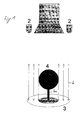
- Figure 1 shows a circular retro-reflective surface 3, to which at its midpoint a perpendicularly projecting from the reflective surface 3 spacer 4a is fixed, on which a serving as an absorbing object light absorbing ball 4 is arranged.
- light emitters 2 light L is emitted to the shown marker assembly 3, 4, which is reflected by the reflecting surface 3 only in the area not covered by the light-absorbing sphere 4.
- This reflection pattern can be detected by a video camera 1, which is based on the embodiment shown in the embodiment ring-shaped reflection image can recognize how the position of the marker 3, 4 or a reference star formed of a plurality of markers in space.
- a reflection shadow generated by one or more absorbing objects 4 is detected, which enables a sharp demarcation between the reflective and weak or non-reflective region of the reflective surface 3, whereby the detection accuracy can be increased according to the invention.
Landscapes
- Health & Medical Sciences (AREA)
- Surgery (AREA)
- Life Sciences & Earth Sciences (AREA)
- Engineering & Computer Science (AREA)
- Heart & Thoracic Surgery (AREA)
- Biomedical Technology (AREA)
- Nuclear Medicine, Radiotherapy & Molecular Imaging (AREA)
- Medical Informatics (AREA)
- Molecular Biology (AREA)
- Animal Behavior & Ethology (AREA)
- General Health & Medical Sciences (AREA)
- Public Health (AREA)
- Veterinary Medicine (AREA)
- Pathology (AREA)
- Oral & Maxillofacial Surgery (AREA)
- Robotics (AREA)
- Length Measuring Devices By Optical Means (AREA)
Abstract
Description
- Die vorliegende Erfindung bezieht sich auf einen Marker und insbesondere auf eine Markeranordnung, wie sie insbesondere für ein Navigationssystem zur Bestimmung der räumlichen Position zum Beispiel eines chirurgischen Instrumentes geeignet ist, sowie auf ein Verfahren zum Detektieren der Position eines Markers.
- Marker werden verwendet, um zum Beispiel bei bildunterstützten chirurgischen Verfahren (IGS; Image Guided Surgery) die Position von mit zum Beispiel mehreren Markern in Form eines Referenzsternes verbundenen chirurgischen Instrumenten oder Körpern durch eine optische Erfassung des von den Markern reflektierten Lichtes zu ermitteln und basierend auf den ermittelten Positionsinformationen einen chirurgischen Eingriff durchzuführen.
- Das Reflexionsvermögen von kugelförmigen passiven Markern ist nicht homogen, da die auf die Kugeloberfläche aufgebrachte retro-reflektive Folie oder eine Beschichtung nur innerhalb eines bestimmten Winkelbereiches ein gutes Reflexionsvermögen aufweist. Jedoch ist der Grenzwinkel für das Reflexionsvermögen nicht mit hoher Genauigkeit reproduzierbar, so dass das Reflexionsvermögen am sichtbaren Rand eines Markers nicht definiert bestimmbar ist. Die Inhomogenität des Reflexionsvermögens eines Markers wird zusätzliche durch das Aufbringen der Folie auf die kugelförmige Basis verstärkt, wodurch es zu nicht definierten Verzerrungen der reflektierenden Folie kommt. Demzufolge ist die Genauigkeit der Positionsbestimmung eines Tracking-Systems begrenzt, insbesondere wenn Marker-Erkennungs-Algorithmen verwendet werden, welche auf der Detektion des Massenmittelpunktes basieren.
- Werden flache Marker verwendet, so kann, wenn der Massenmittelpunkt der Reflexion eines zum Beispiel schräg zur Erfassungsebene liegenden kreisförmigen reflektierenden Markers detektiert wird, eine Positionsungenauigkeit dadurch zustande kommen, dass der kreisförmige in die Kameraebene projizierte reflektierende Marker eine Ellipse ist, deren Massenmittelpunkt nicht exakt beim Mittelpunkt des kreisförmigen Markers liegt. Weiterhin können Ungenauigkeiten beim Aufbringen der Folie auftreten.
- Aus der
GB-2,404,453 A - Es ist eine Aufgabe der vorliegenden Erfindung einen Marker, welcher kostengünstig hergestellt werden kann und eine sichere Positionsdetektion ermöglicht, sowie ein Verfahren zum sicheren Detektieren eines solchen Markers vorzuschlagen.
- Ein erfindungsgemäßer Marker oder eine Markeranordnung, insbesondere zur Verwendung in Verbindung mit einem Navigationssystem, weist eine Licht reflektierende zum Beispiel eben oder flach ausgebildete oder eine oder mehrere Krümmungen aufweisende Oberfläche auf, wobei ein Licht absorbierendes oder intransparentes oder opakes Objekt in einem definierten Abstand von z.B. 0, 0.5, 1.0 oder mehr als 1.0 mm oder auch mit einem variablen Abstand zur reflektierenden Oberfläche angebracht ist. Das Licht absorbierende oder nicht-reflektierende Objekt kann jedes bekannte dreidimensionale Objekt sein, wie zum Beispiel eine Kugel, ein Quader, ein Ellipsoid oder ein anderes Objekt, dessen Form vorzugsweise einfach ermittelt und mathematisch beschrieben werden kann und ist mit der reflektierenden Oberfläche vorzugsweise fest verbunden, zum Beispiel mittels eines Abstandhalters oder Stabes, welcher zum Beispiel an einem definierten Punkt der reflektierenden Oberfläche, wie zum Beispiel in der Mitte der reflektierenden Oberfläche, angeordnet sein kann und zum Beispiel auf den Mittelpunkt einer als absorbierendes Objekt dienenden Kugel gerichtet ist.
- Mit einem erfindungsgemäßen Marker oder einer Markeranordnung kann eine höhere Genauigkeit bei der Positionserkennung erzielt werden, da zum Beispiel im Falle der Verwendung einer Kugel als Licht absorbierendes Objekt das von einer Kamera erfassbare Markerbild ein exakter Kreis mit scharfem und gut erkennbarem Umriss ist und somit zuverlässigere Kreisdetektionsalgorithmen verwendet werden können. Weiterhin besitzt das Marker-Bild einen hohen Kontrast, d.h. eine scharfe Kontur beim Übergang zwischen einer von einer Kamera erkannten reflektierenden Fläche und der durch das absorbierende Objekt abgeschirmten reflektierenden Fläche, welche z.B. als dunkle Fläche erkannt werden kann. Allgemein kann erfindungsgemäß eine reflektierende Fläche auch mit einem Körper verwendet werden, welcher ein anderes und z.B. schlechteres Reflexionsvermögen als eine bei dem Körper angeordnete reflektierende Fläche hat, wobei von einem Navigationssystem die unterschiedlichen Helligkeiten oder Lichtstärken der erfassten zweidimensionalen Objekt- und Reflexionsflächenbilder erkannt und ausgewertet werden.
- Demgegenüber kann mit bekannten Markern, insbesondere bei mit Folien bezogenen oder beschichteten Markern, kein starker Kontrast realisiert werden.
- Weiterhin ist bei Verwendung des erfindungsgemäßen Markers das von einer Kamera erfassbare Marker-Bild bei gleicher Größe der Marker-Kugel größer, da die im Sichtfeld der Erfassungskamera liegende reflektierende Fläche von der Kugel vollständig abgedeckt wird, wohingegen eine mit einer reflektierenden Substanz beschichtete Marker-Kugel im Randbereich keine volle Reflexion mehr erzeugt und somit ein relativ kleineres Marker-Bild liefert. Da bei der erfindungsgemäßen Markeranordnung das reflektierende Objekt, wie zum Beispiel eine Kugel, nicht mit einer retro-reflektierenden Folie beschichtet sein muss, kann diese auch für weitere Zwecke verwendet werden, wie zum Beispiel als Marker für die Positionsbestimmung mittels eines Lasertrackers (High Precision Laser Range Tracker) oder ein mechanisches Koordinaten-Messgerät.
- Da es erfindungsgemäß möglich ist eine ebene reflektierende Oberfläche zu verwenden, können die Produktionskosten für einen Marker verringert werden.
- Vorzugsweise ist die reflektierende Oberfläche retro-reflektiv und weist zum Beispiel eine kreisförmige oder rechteckige, wie zum Beispiel quadratische, Oberfläche auf, wobei zum Beispiel im Kreismittelpunkt oder im Schwerpunkt der reflektierenden Oberfläche ein an diesem Punkt z.B. senkrecht von der reflektierenden Oberfläche herausragendes Befestigungselement für das absorbierende Objekt angebracht ist.
- Vorteilhaft werden mindestens zwei und zum Beispiel drei oder mehr wie oben beschriebene Marker verwendet, welche beispielsweise als Referenzstern dienen können. Dabei können über einer einzigen oder mehreren unterschiedlichen reflektierenden Oberflächen zwei, drei oder mehr nicht oder schwach reflektierenden oder Licht absorbierende Objekte mit gleicher oder verschiedener Geometrie mit gleichem oder verschiedenem Abstand zur reflektierenden Oberfläche angeordnet werden.
- Gemäß einem weiteren Aspekt bezieht sich die Erfindung auf ein optisches z.B. passives Navigationssystem mit bevorzugt mindestens einer Lichtquelle zur Emission von Licht, wobei unter Licht im Sinne der Erfindung jede Form elektro-magnetischer Wellen verstanden werden kann, wie zum Beispiel Licht im sichtbaren oder Infrarot-Bereich. Weiterhin weist das Navigationssystem mindestens eine wie oben beschriebene Markeranordnung auf, wobei von mindestens einer Kamera das von der Lichtquelle emittierte und von der reflektierenden Oberfläche reflektierte Licht erfasst wird. Die Kamera ist mit einer Recheneinheit verbunden, welche die von der Kamera erfassten optischen Signale auswertet und den durch das oberhalb der reflektierenden Oberfläche im Sichtbereich der Kamera liegende absorbierende Objekt erzeugten dunklen oder nicht-reflektierenden Bereich innerhalb der reflektierenden Oberfläche erkennt und hieraus z.B. in Verbindung mit der Information über die Markeranordnung oder Geometrie der Markeranordnung, d.h. z.B. der bekannten in einer Datenbank gespeicherten Information über die Form des absorbierenden Objektes und dessen Abstand von der reflektierenden Oberfläche, die Position des Markers oder der Markeranordnung oder eines Referenzsternes im Raum berechnet.
- Gemäß einem weiteren Aspekt bezieht sich die Erfindung auf ein Verfahren zum Detektieren einer wie oben beschriebenen Markeranordnung, wobei ermittelt wird, ob ein von einer Kamera erfasstes Bild oder Teilbild der reflektierenden Oberfläche ein absorbierendes die Oberfläche zumindest zum Teil abschirmendes Objekt aufweist und überprüft wird, ob der nur schwach oder nicht-reflektierende Bereich vollständig von einem reflektierenden Bereich umgeben wird oder nicht. Falls der nicht-reflektierende Bereich vollständig von einem reflektierenden Bereich umgeben wird, so kann die Position des absorbierenden Objektes zum Beispiel durch Bestimmung des Mittelpunktes eines Kreises im Falle der Verwendung einer Kugel als absorbierendes Objekt bestimmt werden. Falls der nicht-reflektierende Bereich nicht vollständig von einem reflektierenden Bereich umgeben wird, so kann erkannt werden, dass sich aus dem Blickwinkel der Erfassungskamera gesehen das absorbierende Objekt nicht mehr vollständig vor einer reflektierenden darunter liegenden Oberfläche befindet, so dass diese Erfassungsdaten der Kamera als fehlerhaft erkannt werden können. Wird somit bei dem erfindungsgemäßen Verfahren festgestellt, dass das Abbild des absorbierenden Objektes aus der reflektierenden Oberfläche herauswandert, so kann ein Fehler detektiert werden, wodurch das Fehlerdektektionsrisiko, also die falsche Bestimmung der Position eines Markers, ausgeschlossen werden kann.
- Vorzugsweise wird das erfindungsgemäße Verfahren zum Kalibrieren zum Beispiel einer Kamera, eines Navigationssystems, eines medizinischen Instrumentes oder eines Patienten verwendet, mit welchem die Marker verbunden sind, wobei die Marker nur relativ wenig bewegt werden.
- Gemäß einem weitern Aspekt bezieht sich die Erfindung auf ein Computerprogramm, welches, wenn es in einen Computer geladen ist oder auf einem Computer läuft, das oben beschriebene Verfahren durchführt. Ebenso bezieht sich die Erfindung auf ein Programmspeichermedium oder Computerprogrammprodukt mit einem solchen Programm.
- Die Erfindung wird nachfolgend anhand eines Ausführungsbeispieles beschrieben.
- Es zeigt:
- Figur 1
- ein Navigationssystem zur Erfassung eines erfindungsgemäßen Markers.
- Figur 1 zeigt eine kreisförmige retro-reflektierende Fläche 3, an welcher an deren Mittelpunkt ein senkrecht von der reflektierenden Fläche 3 vorstehendes Abstandselement 4a befestigt ist, auf welchem eine als absorbierendes Objekt dienende Licht absorbierende Kugel 4 angeordnet ist. Von Lichtemittern 2 wird Licht L auf die gezeigte Markeranordnung 3, 4 ausgesandt, welches von der reflektierenden Fläche 3 nur in dem nicht von der Licht absorbierenden Kugel 4 abgedeckten Bereich reflektiert wird. Dieses Reflexionsmuster kann von einer Videokamera 1 erfasst werden, welche anhand des im gezeigten Ausführungsbeispiel ringförmigen Reflexions-Bildes erkennen kann wie die Position des Markers 3, 4 oder eines aus mehreren Markern gebildeten Referenzsterns im Raum ist.
- Erfindungsgemäß wird somit neben einem Reflexionsbild auch ein von einem oder mehreren absorbierenden Objekten 4 erzeugter Reflexions-Schatten detektiert, welcher eine scharfe Abgrenzung zwischen dem reflektierenden und schwach oder nicht reflektierenden Bereich der reflektierenden Fläche 3 ermöglicht, wodurch erfindungsgemäß die Erfassungsgenauigkeit erhöht werden kann.
Claims (14)
- Marker für ein Navigationssystem mit einer reflektierenden Oberfläche (3) und einem Licht absorbierenden oder nicht oder nur schwach reflektierenden Objekt (4), welches in einem definierten Abstand zur reflektierenden Oberfläche (3) angeordnet ist.
- Marker bestehend aus einer reflektierenden Oberfläche (3) und einem Licht absorbierenden oder nicht oder nur schwach reflektierenden Objekt (4), welches in einem festen oder variablen Abstand vor der reflektierenden Oberfläche (3) angeordnet ist.
- Marker nach Anspruch 1 oder 2, wobei die reflektierende Oberfläche (3) eine ebene oder gekrümmte Oberfläche ist.
- Marker nach einem der vorhergehenden Ansprüche, wobei das absorbierende Objekt (4) eine Kugel oder kugelförmig ist.
- Marker nach einem der vorhergehenden Ansprüche, wobei das absorbierende Objekt (4) fest mit der reflektierenden Oberfläche mittels eines Verbindungselements (4a) verbunden ist.
- Marker nach einem der vorhergehenden Ansprüche, wobei die reflektierende Oberfläche (3) kreisförmig, rechteckig oder quadratisch ist.
- Marker nach einem der vorhergehenden Ansprüche, wobei die reflektierende Oberfläche (3) retro-reflektiv ist.
- Markeranordnung mit mindestens zwei oder drei Markern nach einem der vorhergehenden Ansprüche.
- Navigationssystem mit mindestens einem Marker (3, 4) nach einem der Ansprüche 1 bis 7 oder mindestens einer Markeranordnung nach Anspruch 8, mindestens einer Kamera (1), welche ein Reflexionsbild des mindestens einen Markers (3, 4) erfassen kann und einer Recheneinheit, welche mit der Kamera (1) verbunden ist und anhand des Reflexionsbildes des mindestens einen Markers (3, 4) die Position des Markers (3, 4) oder der Markeranordnung im Raum bestimmen kann.
- Navigationssystem nach Anspruch 9 mit mindestens einer Lichtquelle (2) zur Beleuchtung des mindestens einen Markers (3, 4).
- Verfahren zum Detektieren einer Position eines Markers oder einer Markeranordnung (3, 4) nach einem der Ansprüche 1 bis 8, wobei ermittelt wird, ob in dem Reflexionsbild eine Licht nicht reflektierende Fläche vollständig von einer Licht reflektierenden Fläche umgeben wird, um zu bestimmen, ob eine Fehldetektion vorliegt.
- Verfahren nach dem vorhergehenden Anspruch, wobei das Detektionsverfahren zum Kalibrieren einer Kamera, eines Navigationssystems, eines Instruments oder Körpers verwendet wird.
- Computerprogramm, welches, wenn es auf einem Computer läuft oder in einen Computer geladen wird, das Verfahren nach einem der beiden vorhergehenden Ansprüche durchführt.
- Programmspeichermedium oder Computerprogrammprodukt mit dem Programm nach dem vorhergehenden Anspruch.
Priority Applications (4)
| Application Number | Priority Date | Filing Date | Title |
|---|---|---|---|
| DE502005004417T DE502005004417D1 (de) | 2005-10-12 | 2005-10-12 | Marker für ein Navigationssystem und Verfahren zum Detektieren eines Markers |
| EP05022214A EP1774922B1 (de) | 2005-10-12 | 2005-10-12 | Marker für ein Navigationssystem und Verfahren zum Detektieren eines Markers |
| US11/548,848 US20070167708A1 (en) | 2005-10-12 | 2006-10-12 | Marker for a navigation system and method for detecting a marker |
| US14/497,447 US20150018672A1 (en) | 2005-10-12 | 2014-09-26 | Marker for a navigation system and method for detecting a marker |
Applications Claiming Priority (1)
| Application Number | Priority Date | Filing Date | Title |
|---|---|---|---|
| EP05022214A EP1774922B1 (de) | 2005-10-12 | 2005-10-12 | Marker für ein Navigationssystem und Verfahren zum Detektieren eines Markers |
Publications (2)
| Publication Number | Publication Date |
|---|---|
| EP1774922A1 true EP1774922A1 (de) | 2007-04-18 |
| EP1774922B1 EP1774922B1 (de) | 2008-06-11 |
Family
ID=35976785
Family Applications (1)
| Application Number | Title | Priority Date | Filing Date |
|---|---|---|---|
| EP05022214A Expired - Lifetime EP1774922B1 (de) | 2005-10-12 | 2005-10-12 | Marker für ein Navigationssystem und Verfahren zum Detektieren eines Markers |
Country Status (3)
| Country | Link |
|---|---|
| US (2) | US20070167708A1 (de) |
| EP (1) | EP1774922B1 (de) |
| DE (1) | DE502005004417D1 (de) |
Cited By (2)
| Publication number | Priority date | Publication date | Assignee | Title |
|---|---|---|---|---|
| DE102008022254A1 (de) | 2008-05-06 | 2009-11-12 | Bernhard Hauri | Marker für ein Navigationssystem |
| EP2161597A1 (de) * | 2008-09-03 | 2010-03-10 | BrainLAB AG | Retroreflektor für bildgestützte Operationssysteme |
Families Citing this family (26)
| Publication number | Priority date | Publication date | Assignee | Title |
|---|---|---|---|---|
| US9668820B2 (en) | 2009-08-20 | 2017-06-06 | Brainlab Ag | Integrated surgical device combining instrument, tracking system and navigation system |
| EP2605719B1 (de) | 2010-08-16 | 2016-04-06 | Brainlab AG | Medizinischer marker, verfahren und vorrichtung zur herstellung eines medizinischen markers |
| GB2536650A (en) | 2015-03-24 | 2016-09-28 | Augmedics Ltd | Method and system for combining video-based and optic-based augmented reality in a near eye display |
| US12458411B2 (en) | 2017-12-07 | 2025-11-04 | Augmedics Ltd. | Spinous process clamp |
| US12521201B2 (en) | 2017-12-07 | 2026-01-13 | Augmedics Ltd. | Spinous process clamp |
| WO2019211741A1 (en) | 2018-05-02 | 2019-11-07 | Augmedics Ltd. | Registration of a fiducial marker for an augmented reality system |
| US10939977B2 (en) | 2018-11-26 | 2021-03-09 | Augmedics Ltd. | Positioning marker |
| US11766296B2 (en) | 2018-11-26 | 2023-09-26 | Augmedics Ltd. | Tracking system for image-guided surgery |
| DK3948470T3 (da) * | 2019-04-02 | 2022-10-24 | Zauberzeug Gmbh | Optisk positionsmarkering, robot med sådan markering og styresystem til en sådan robot |
| US11980506B2 (en) | 2019-07-29 | 2024-05-14 | Augmedics Ltd. | Fiducial marker |
| US12178666B2 (en) | 2019-07-29 | 2024-12-31 | Augmedics Ltd. | Fiducial marker |
| US11382712B2 (en) | 2019-12-22 | 2022-07-12 | Augmedics Ltd. | Mirroring in image guided surgery |
| US11389252B2 (en) | 2020-06-15 | 2022-07-19 | Augmedics Ltd. | Rotating marker for image guided surgery |
| US12502163B2 (en) | 2020-09-09 | 2025-12-23 | Augmedics Ltd. | Universal tool adapter for image-guided surgery |
| US12239385B2 (en) | 2020-09-09 | 2025-03-04 | Augmedics Ltd. | Universal tool adapter |
| WO2022150284A1 (en) | 2021-01-06 | 2022-07-14 | Mako Surgical Corp. | Tracker for a navigation system |
| US11896445B2 (en) | 2021-07-07 | 2024-02-13 | Augmedics Ltd. | Iliac pin and adapter |
| US12150821B2 (en) | 2021-07-29 | 2024-11-26 | Augmedics Ltd. | Rotating marker and adapter for image-guided surgery |
| WO2023021451A1 (en) | 2021-08-18 | 2023-02-23 | Augmedics Ltd. | Augmented reality assistance for osteotomy and discectomy |
| WO2023203521A1 (en) | 2022-04-21 | 2023-10-26 | Augmedics Ltd. | Systems and methods for medical image visualization |
| EP4302718B1 (de) * | 2022-07-06 | 2025-08-27 | Ecential Robotics | Chirurgisches navigationssystem |
| IL319523A (en) | 2022-09-13 | 2025-05-01 | Augmedics Ltd | Augmented reality glasses for image-guided medical intervention |
| USD1139999S1 (en) | 2023-08-18 | 2026-08-04 | Stryker European Operations Limited | Surgical instrument |
| USD1120320S1 (en) | 2023-08-18 | 2026-03-24 | Mako Surgical Corp. | Surgical tracker |
| USD1117755S1 (en) | 2023-08-18 | 2026-03-10 | Mako Surgical Corp. | Surgical tracker |
| USD1121826S1 (en) | 2023-08-18 | 2026-04-07 | Stryker European Operations Limited | Surgical tracker |
Citations (6)
| Publication number | Priority date | Publication date | Assignee | Title |
|---|---|---|---|---|
| US20020188194A1 (en) * | 1991-01-28 | 2002-12-12 | Sherwood Services Ag | Surgical positioning system |
| DE10306793A1 (de) * | 2002-05-21 | 2003-12-04 | Plus Endoprothetik Ag Rotkreuz | Anordnung und Verfahren zur intraoperativen Festlegung der Lage eines Gelenkersatzimplantats |
| US6675040B1 (en) * | 1991-01-28 | 2004-01-06 | Sherwood Services Ag | Optical object tracking system |
| US20040167393A1 (en) * | 2003-02-25 | 2004-08-26 | Solar Matthew S. | Fiducial marker devices, tools, and methods |
| DE202004011567U1 (de) * | 2004-07-23 | 2004-11-18 | Aesculap Ag & Co. Kg | Reflektorelement für einen Marker eines chirurgischen Navigationssystems |
| GB2404453A (en) | 2003-07-30 | 2005-02-02 | Simon Alexander Telfer | Retro reflective video marker |
Family Cites Families (19)
| Publication number | Priority date | Publication date | Assignee | Title |
|---|---|---|---|---|
| US2534824A (en) * | 1947-07-09 | 1950-12-19 | Anna A Jones | Gyroscopic navigational device |
| US4631676A (en) * | 1983-05-25 | 1986-12-23 | Hospital For Joint Diseases Or | Computerized video gait and motion analysis system and method |
| DE3703998A1 (de) * | 1986-06-14 | 1987-12-17 | Roland Man Druckmasch | Einrichtung an druckmaschinen mit stelleinrichtungen fuer umfangs-, seiten- und diagonalregister |
| US5203346A (en) * | 1990-03-30 | 1993-04-20 | Whiplash Analysis, Inc. | Non-invasive method for determining kinematic movement of the cervical spine |
| US5570301A (en) * | 1994-07-15 | 1996-10-29 | Mitsubishi Electric Information Technology Center America, Inc. | System for unencumbered measurement and reporting of body posture |
| US6246898B1 (en) * | 1995-03-28 | 2001-06-12 | Sonometrics Corporation | Method for carrying out a medical procedure using a three-dimensional tracking and imaging system |
| US5596990A (en) * | 1995-06-06 | 1997-01-28 | Yock; Paul | Rotational correlation of intravascular ultrasound image with guide catheter position |
| US5727554A (en) * | 1996-09-19 | 1998-03-17 | University Of Pittsburgh Of The Commonwealth System Of Higher Education | Apparatus responsive to movement of a patient during treatment/diagnosis |
| US5926780A (en) * | 1997-10-09 | 1999-07-20 | Tweed Fox | System for measuring the initial velocity vector of a ball and method of use |
| US6177682B1 (en) * | 1998-10-21 | 2001-01-23 | Novacam Tyechnologies Inc. | Inspection of ball grid arrays (BGA) by using shadow images of the solder balls |
| US6973202B2 (en) * | 1998-10-23 | 2005-12-06 | Varian Medical Systems Technologies, Inc. | Single-camera tracking of an object |
| US6475226B1 (en) * | 1999-02-03 | 2002-11-05 | Scimed Life Systems, Inc. | Percutaneous bypass apparatus and method |
| US6411215B1 (en) * | 1999-02-19 | 2002-06-25 | J. Mitchell Shnier | Optical methods for detecting the position or state of an object |
| US6978167B2 (en) * | 2002-07-01 | 2005-12-20 | Claron Technology Inc. | Video pose tracking system and method |
| US6946648B2 (en) * | 2003-03-31 | 2005-09-20 | Council Of Scientific And Industrial Research | Opto-electronic device for angle generation of ultrasonic probe |
| US7203277B2 (en) * | 2003-04-25 | 2007-04-10 | Brainlab Ag | Visualization device and method for combined patient and object image data |
| US20050109855A1 (en) * | 2003-11-25 | 2005-05-26 | Mccombs Daniel | Methods and apparatuses for providing a navigational array |
| WO2005096982A1 (en) * | 2004-03-31 | 2005-10-20 | Smith & Nephew, Inc. | Methods and apparatuses for providing a reference array input device |
| US20050245820A1 (en) * | 2004-04-28 | 2005-11-03 | Sarin Vineet K | Method and apparatus for verifying and correcting tracking of an anatomical structure during surgery |
-
2005
- 2005-10-12 DE DE502005004417T patent/DE502005004417D1/de not_active Expired - Lifetime
- 2005-10-12 EP EP05022214A patent/EP1774922B1/de not_active Expired - Lifetime
-
2006
- 2006-10-12 US US11/548,848 patent/US20070167708A1/en not_active Abandoned
-
2014
- 2014-09-26 US US14/497,447 patent/US20150018672A1/en not_active Abandoned
Patent Citations (6)
| Publication number | Priority date | Publication date | Assignee | Title |
|---|---|---|---|---|
| US20020188194A1 (en) * | 1991-01-28 | 2002-12-12 | Sherwood Services Ag | Surgical positioning system |
| US6675040B1 (en) * | 1991-01-28 | 2004-01-06 | Sherwood Services Ag | Optical object tracking system |
| DE10306793A1 (de) * | 2002-05-21 | 2003-12-04 | Plus Endoprothetik Ag Rotkreuz | Anordnung und Verfahren zur intraoperativen Festlegung der Lage eines Gelenkersatzimplantats |
| US20040167393A1 (en) * | 2003-02-25 | 2004-08-26 | Solar Matthew S. | Fiducial marker devices, tools, and methods |
| GB2404453A (en) | 2003-07-30 | 2005-02-02 | Simon Alexander Telfer | Retro reflective video marker |
| DE202004011567U1 (de) * | 2004-07-23 | 2004-11-18 | Aesculap Ag & Co. Kg | Reflektorelement für einen Marker eines chirurgischen Navigationssystems |
Cited By (3)
| Publication number | Priority date | Publication date | Assignee | Title |
|---|---|---|---|---|
| DE102008022254A1 (de) | 2008-05-06 | 2009-11-12 | Bernhard Hauri | Marker für ein Navigationssystem |
| EP2161597A1 (de) * | 2008-09-03 | 2010-03-10 | BrainLAB AG | Retroreflektor für bildgestützte Operationssysteme |
| US8456649B2 (en) | 2008-09-03 | 2013-06-04 | Brainlab Ag | Retro-reflector for image-guided operation systems |
Also Published As
| Publication number | Publication date |
|---|---|
| US20150018672A1 (en) | 2015-01-15 |
| US20070167708A1 (en) | 2007-07-19 |
| EP1774922B1 (de) | 2008-06-11 |
| DE502005004417D1 (de) | 2008-07-24 |
Similar Documents
| Publication | Publication Date | Title |
|---|---|---|
| EP1774922B1 (de) | Marker für ein Navigationssystem und Verfahren zum Detektieren eines Markers | |
| US7962196B2 (en) | Method and system for determining the location of a medical instrument relative to a body structure | |
| DE112007000340T5 (de) | Retroreflektierende Markenverfolgungssysteme | |
| DE102009005188B4 (de) | Magnetresonanztomographie-Vorrichtung mit einer Lokalspule und Verfahren zum Detektieren der Position der Lokalspule | |
| EP1900336B1 (de) | Vorrichtung und Verfahren zum Messen geometrischer Eigenschaften medizintechnischer Behandlungsvorrichtungen, insbesondere zur automatischen Verifikation, Kalibrierung und Vermessung von Instrumenten für computerassistierte Chirurgie | |
| EP3281600A1 (de) | Marker zur optischen verfolgung, system zur optischen verfolgung und verfahren zur optischen verfolgung | |
| DE102005043912B4 (de) | Verfahren zum Bestimmen der 3D-Koordinaten der Oberfläche eines Objekts | |
| DE102015212352A1 (de) | Verfahren, Anordnung und Computerprogrammprodukt zur Lageerfassung eines zu untersuchenden Objekts | |
| EP2915022B1 (de) | Verfahren zum eingeben eines steuerbefehls für eine komponente eines kraftwagens | |
| EP1498688B1 (de) | Lokator und optisches Messsystem | |
| EP1420264A1 (de) | Verfahren und Vorrichtung zur Kalibrierung eines Messsystems | |
| DE19825221A1 (de) | Optische Faser-Meßeinrichtung zur Positionsmessung | |
| DE102018208203B4 (de) | Targetkörper, Anordnung mit Targetkörper und Verfahren zum Ermitteln einer Position und/oder einer Ausrichtung eines Targetkörpers | |
| DE102010042278A1 (de) | Operationsnavigationssystem mit strukturiertem Licht | |
| EP1636542A1 (de) | Verfahren und messvorrichtung zur berühungslosen messung von winkeln oder winkeländerungen an gegenständen | |
| CN109938843A (zh) | 光学跟踪系统及光学跟踪方法 | |
| DE10246147B4 (de) | Mehrkamera-Trackingsystem | |
| DE102021130148A1 (de) | Fehlerkompensation für ein dreidimensionales verfolgungssystem | |
| DE102011010412A1 (de) | Ultraschallnavigierte Punktion | |
| DE102012002412A1 (de) | Ultraschallnavigierte Punktion | |
| DE102018010361B4 (de) | Targetkörper mit einer Mehrzahl von Markern, Anordnung mit Targetkörper und Verfahren zum Ermitteln einer Position und/oder einer Ausrichtung eines Targetkörpers | |
| EP3278059B1 (de) | System und verfahren zum ermitteln der relativen verlagerung zweier körper zueinander | |
| DE10225077A1 (de) | Trackingsystem | |
| EP3374732B1 (de) | Verfahren und vorrichtung zur bestimmung der räumlichen position eines gegenstandes mittels interferometrischer längenmessung | |
| EP1667067A1 (de) | Verfahren und Vorrichtung zum Kalibrieren eines medizinischen Instrumentes |
Legal Events
| Date | Code | Title | Description |
|---|---|---|---|
| PUAI | Public reference made under article 153(3) epc to a published international application that has entered the european phase |
Free format text: ORIGINAL CODE: 0009012 |
|
| 17P | Request for examination filed |
Effective date: 20051012 |
|
| AK | Designated contracting states |
Kind code of ref document: A1 Designated state(s): AT BE BG CH CY CZ DE DK EE ES FI FR GB GR HU IE IS IT LI LT LU LV MC NL PL PT RO SE SI SK TR |
|
| AX | Request for extension of the european patent |
Extension state: AL BA HR MK YU |
|
| AKX | Designation fees paid |
Designated state(s): DE FR GB IT |
|
| GRAP | Despatch of communication of intention to grant a patent |
Free format text: ORIGINAL CODE: EPIDOSNIGR1 |
|
| GRAS | Grant fee paid |
Free format text: ORIGINAL CODE: EPIDOSNIGR3 |
|
| GRAA | (expected) grant |
Free format text: ORIGINAL CODE: 0009210 |
|
| AK | Designated contracting states |
Kind code of ref document: B1 Designated state(s): DE FR GB IT |
|
| REG | Reference to a national code |
Ref country code: GB Ref legal event code: FG4D Free format text: NOT ENGLISH |
|
| REF | Corresponds to: |
Ref document number: 502005004417 Country of ref document: DE Date of ref document: 20080724 Kind code of ref document: P |
|
| RAP2 | Party data changed (patent owner data changed or rights of a patent transferred) |
Owner name: BRAINLAB AG |
|
| PLBE | No opposition filed within time limit |
Free format text: ORIGINAL CODE: 0009261 |
|
| STAA | Information on the status of an ep patent application or granted ep patent |
Free format text: STATUS: NO OPPOSITION FILED WITHIN TIME LIMIT |
|
| 26N | No opposition filed |
Effective date: 20090312 |
|
| PG25 | Lapsed in a contracting state [announced via postgrant information from national office to epo] |
Ref country code: IT Free format text: LAPSE BECAUSE OF FAILURE TO SUBMIT A TRANSLATION OF THE DESCRIPTION OR TO PAY THE FEE WITHIN THE PRESCRIBED TIME-LIMIT Effective date: 20080611 |
|
| PG25 | Lapsed in a contracting state [announced via postgrant information from national office to epo] |
Ref country code: GB Free format text: LAPSE BECAUSE OF NON-PAYMENT OF DUE FEES Effective date: 20091012 |
|
| REG | Reference to a national code |
Ref country code: DE Ref legal event code: R082 Ref document number: 502005004417 Country of ref document: DE Representative=s name: SCHWABE SANDMAIR MARX, DE |
|
| REG | Reference to a national code |
Ref country code: DE Ref legal event code: R081 Ref document number: 502005004417 Country of ref document: DE Owner name: BRAINLAB AG, DE Free format text: FORMER OWNER: BRAINLAB AG, 85622 FELDKIRCHEN, DE Effective date: 20131104 Ref country code: DE Ref legal event code: R082 Ref document number: 502005004417 Country of ref document: DE Representative=s name: SCHWABE SANDMAIR MARX, DE Effective date: 20131104 Ref country code: DE Ref legal event code: R082 Ref document number: 502005004417 Country of ref document: DE Representative=s name: SCHWABE SANDMAIR MARX PATENTANWAELTE RECHTSANW, DE Effective date: 20131104 |
|
| REG | Reference to a national code |
Ref country code: FR Ref legal event code: CD Owner name: BRAINLAB AG Effective date: 20131122 Ref country code: FR Ref legal event code: CA Effective date: 20131122 |
|
| PGFP | Annual fee paid to national office [announced via postgrant information from national office to epo] |
Ref country code: FR Payment date: 20141022 Year of fee payment: 10 Ref country code: DE Payment date: 20141022 Year of fee payment: 10 |
|
| REG | Reference to a national code |
Ref country code: DE Ref legal event code: R119 Ref document number: 502005004417 Country of ref document: DE |
|
| PG25 | Lapsed in a contracting state [announced via postgrant information from national office to epo] |
Ref country code: DE Free format text: LAPSE BECAUSE OF NON-PAYMENT OF DUE FEES Effective date: 20160503 |
|
| REG | Reference to a national code |
Ref country code: FR Ref legal event code: ST Effective date: 20160630 |
|
| PG25 | Lapsed in a contracting state [announced via postgrant information from national office to epo] |
Ref country code: FR Free format text: LAPSE BECAUSE OF NON-PAYMENT OF DUE FEES Effective date: 20151102 |