EP1774716B1 - Inline intrusion detection using a single physical port - Google Patents
Inline intrusion detection using a single physical port Download PDFInfo
- Publication number
- EP1774716B1 EP1774716B1 EP05773236.4A EP05773236A EP1774716B1 EP 1774716 B1 EP1774716 B1 EP 1774716B1 EP 05773236 A EP05773236 A EP 05773236A EP 1774716 B1 EP1774716 B1 EP 1774716B1
- Authority
- EP
- European Patent Office
- Prior art keywords
- packet
- network
- communicating
- tagged
- processor
- Prior art date
- Legal status (The legal status is an assumption and is not a legal conclusion. Google has not performed a legal analysis and makes no representation as to the accuracy of the status listed.)
- Active
Links
- 238000001514 detection method Methods 0.000 title claims description 16
- 238000000034 method Methods 0.000 claims description 13
- 238000012545 processing Methods 0.000 claims description 6
- 230000003139 buffering effect Effects 0.000 claims description 3
- 239000000872 buffer Substances 0.000 description 12
- 238000004891 communication Methods 0.000 description 9
- 230000008901 benefit Effects 0.000 description 7
- 230000003287 optical effect Effects 0.000 description 4
- 230000002265 prevention Effects 0.000 description 4
- 230000009471 action Effects 0.000 description 3
- 230000004075 alteration Effects 0.000 description 2
- 238000012986 modification Methods 0.000 description 2
- 230000004048 modification Effects 0.000 description 2
- 238000012544 monitoring process Methods 0.000 description 2
- 238000000844 transformation Methods 0.000 description 2
- 230000009466 transformation Effects 0.000 description 2
- 230000005540 biological transmission Effects 0.000 description 1
- 230000008859 change Effects 0.000 description 1
- 238000000926 separation method Methods 0.000 description 1
- 230000001360 synchronised effect Effects 0.000 description 1
- 238000012546 transfer Methods 0.000 description 1
- 238000013519 translation Methods 0.000 description 1
Images

Classifications
-
- H—ELECTRICITY
- H04—ELECTRIC COMMUNICATION TECHNIQUE
- H04L—TRANSMISSION OF DIGITAL INFORMATION, e.g. TELEGRAPHIC COMMUNICATION
- H04L63/00—Network architectures or network communication protocols for network security
- H04L63/14—Network architectures or network communication protocols for network security for detecting or protecting against malicious traffic
- H04L63/1408—Network architectures or network communication protocols for network security for detecting or protecting against malicious traffic by monitoring network traffic
- H04L63/1416—Event detection, e.g. attack signature detection
Definitions
- the present invention relates generally to the field of network security, and more particularly to inline intrusion detection using a single physical port.
- Intrusion detection systems generally operate in one of two modes. In “promiscuous” mode, the IDS monitors incoming network traffic to determine whether a particular pattern characteristic of an intrusion can be observed. In “inline” mode, network traffic is scanned by the IDS to determine whether it contains a hostile signature. If a hostile signature is detected, the IDS prevents the network from receiving the traffic. Generally, inline IDSs have two physical ports, one coupled to the outside network and one coupled to the protected network. On the other hand, IDSs operating in promiscuous mode only need one physical port to receive network traffic.
- US 2003/084326 discloses a method of identifying data comprised in a network exploit comprising receiving a packet by an intrusion prevention system maintained by a node of a network, the intrusion prevention system bound to a media access control driver and a protocol driver, invoking a signature analysis algorithm by the intrusion prevention system, and comparing the packet by the intrusion prevention system with a first rule set comprising a rule logically defining a packet signature is provided.
- US 2004/030927 discloses a method for processing data packets, which includes receiving the data packet, examining the data packet, determining a single flow record associated with the packet and extracting flow instructions for two or more devices from the single flow record.
- a method for inline intrusion detection includes receiving a packet at a physical interface of an intrusion detection system.
- the packet is tagged with a first VLAN identifier associated with an external network.
- the network further includes buffering the packet at the physical interface, communicating a copy of the packet to a processor, and analyzing the copy of the packet at the processor to determine whether the packet includes an attack signature.
- the method also includes communicating a reply message from the processor to the interface indicating whether the packet includes an attack signature. If the packet does not contain an attack signature the buffered copy of the packet is re-tagged with a second VLAN identifier associated with a protected network and re-tagged packet is communicated to the protected network.
- an intrusion detection system includes an interface operable to receive a packet that is tagged with a first VLAN identifier associated with an external network.
- the interface is further operable to buffer the packet at the interface, communicate a copy of the packet to a processor, and re-tag the packet with a second VLAN identifier associated with a protected network.
- the intrusion detection system is also operable to communicate the packet to the protected network.
- the processor is operable to analyze the copy of the packet to determine if it includes an attack signature and communicate a reply message to the interface indicating whether the packet includes an attack signature.
- the interface re-tags and communicates the packet only if the reply message indicates that the packet does not include an attack signature.
- Important technical advantages of certain embodiments of the present invention include inline intrusion detection using a single port. This allows single-port intrusion detection systems that may have been used for monitoring to be adapted for use as inline systems. Furthermore, it may provide a lower cost alternative to multiple-port devices used for inline intrusion detection.
- Certain embodiments of the present invention include more efficient use of memory and bus resources in an inline system. Re-tagging packets with a VLAN identifier can be performed at the physical interface. Thus, in contrast with systems that operate at higher layers, such as firewalls, certain embodiments of the present invention allow a packet to be buffered and re-tagged without having to be processed and returned by a processor. This reduces the amount of packet communication between the interface and the processor.
- FIGURE 1 illustrates a computer system 100 that includes an inline intrusion detection system (IDS) 102 between an external network 104 and a protected network 106.
- IDS inline intrusion detection system
- IDS 102 receives information from external network 104 and analyzes the information to determine whether the information includes a signature that is characteristic of a network attack or other hostile action. If an attack is detected, IDS 102 does not send the information to protected network 106. Otherwise, IDS 102 communicates the information to protected network 106.
- IDS inline intrusion detection system
- External network 104 may include any collection of networked communication devices exchanging information.
- Networked communication devices may include hubs, routers, switches, gateways, personal computers, telephones, or any other device that can exchange information.
- Devices in external network 104 may exchange information in the form of packets, cells, frames, segments, or other portions of data (collectively referred to as "packets").
- External network 104 may use any suitable medium or media of transmission, including wireline, wireless, or optical connections.
- Devices in external network 104 may communicate with one another using any number of suitable protocols, such as asynchronous transfer mode (ATM), transport control protocol / Internet protocol (TCP/IP), synchronous optical network (SONET), or Ethernet.
- External network 104 may also include the Internet.
- Protected network 106 represents any collection of communication devices communicating in any suitable manner.
- protected network 106 may include any of the devices and communication media discussed in conjunction with external network 104.
- Protected network 106 may also use one or more suitable communication protocols, such as the ones described above.
- protected network 106 supports the use of virtual local area networks (VLANs).
- VLANs are a logical separation created between devices that share a physical network, so that devices on one VLAN cannot communicate with one another using the existing physical connections between the devices except through suitable network bridging hardware and/or software.
- VLANs are described in IEEE specification 802.1q.
- Network gateway 105 represents any suitable hardware and/or software that communicates traffic received from external network 106 to protected network 106 and IDS 102. Traffic received from external network 106 is automatically tagged with an identifier for a first VLAN. Protected network 106 is configured to be on a second VLAN, so that it does not recognize traffice tagged with the identifier of the first VLAN. Thus, even though network gateway 105 may replicate the information to all of its ports, such as might take place in a network hub, the traffic will not be recognized by protected network 106 unless tagged with the proper VLAN identifier. Network gateway 105 includes a monitoring port that replicates the contents of incoming network traffic for IDS 102.
- IDS 102 is an inline security system that receives traffic from external network 104, analyzes the traffic to determine if it contains an attack signature or other indication of hostile action, and prevents hostile information from reaching protected network 106.
- IDS 102 includes an interface 108, a processor 112, and a memory 114.
- Processor 112 may be any hardware and/or software components suitable for processing information, such as microprocessors, microcontrollers, or digital signal processors (DSPs).
- Memory 114 is any suitable form of information storage, which may include magnetic media, optical media, removable media, local storage, remote storage, or other suitable component.
- memory 114 stores code 116, VLAN tags 118, and attack signatures 120.
- Code 116 is executed by processor 112 to perform any suitable task associated with IDS 102.
- VLAN tags 118 are stored identifiers associated respectively with external network 104 and protected network 106.
- Attack signatures 120 are recognized patterns of information that indicate that an incoming packet represents a hostile action directed at protected network 106.
- Processor 112 compares information to attack signatures 120 to detect attacks.
- Interface 108 represents a physical connection allowing communication between IDS 102 and devices on protected network 106 and external network 104. Communications with interface 102 take place at layer 2 of the Open Systems Interconnect (OSI) model. Interface 108 supports VLAN trunking. VLAN trunking allows interface 108 to recognize and communicate with multiple VLANs, each identified by a particular VLAN tag. Interface 108 therefore effectively includes multiple logical ports, each associated with a particular VLAN. Interface 108 may tag packets and change existing tags appropriately so that a packet is communicated to a particular VLAN.
- OSI Open Systems Interconnect
- interface 108 establishes a first VLAN for external network 104 and a second VLAN for protected network 106.
- interface 108 has two logical ports 110A and 110B.
- Information received from external network 104 is tagged with the VLAN tag associated with the first VLAN network, so it is not recognized by protected network 106.
- interface 106 may re-tag the information with the tag of the second VLAN. This effectively communicates information to protected network 106 using logical port 110B, even though interface 108 only includes one physical connection.
- Interface 108 also includes a buffer 122.
- Buffer 122 represents local information storage at interface 108.
- Buffer 122 may include any suitable form of information storage, such as magnetic media, flash memory, optical media, or other type of information storage medium.
- Buffer 122 stores incoming information from external network 104 while the information is processed by components of IDS 102.
- buffer 122 retains a copy of incoming traffic while the traffic is being analyzed by processor 112 to determine whether the incoming information is hostile.
- network gateway 105 receives traffic from network and tags the traffic with a first VLAN identifier. Network gateway 105 may then broadcast the traffic to all of its ports or may communicate it to IDS 102 only. Protected network 106 is configured to recognize only information on a second VLAN, so even if the packet is broadcast to protected network 106, it will not be recognized.
- IDS 102 receives the traffic at interface 108 and buffers the traffic in buffer 122. IDS 102 communicates a copy of the packet to processor 112, which analyzes the traffic to determine whether it includes an attack signature. Processor 112 then returns a message to IDS 102 indicating whether the packet includes an attack signature or not.
- IDS 102 discards the packet from buffer 112. Otherwise, IDS 102 may re-tag the packet with a second VLAN identifier and communicate the packet back to network gateway 105, which in turn communicates the packet to protected network 106.
- One technical advantage of certain embodiments of the present invention is the opportunity to conserve memory and bus resources in IDS 102. Since VLAN re-tagging may be performed at interface 108, interface 108 does not require additional processing resources to move a packet from one VLAN to another. Conversely, network protection systems that operate at higher layers, such as firewalls, typically require network address translation or other similar adjustments to packet header information. Such systems must forward a packet to the appropriate processing resource using an internal bus, and then receive a returned packet suitably modified for communication to the network protected by these systems. In contrast to these conventional systems, interface 108 may receive a reply message, which may be as short as a single bit, that indicates whether or not the packet should be communicated to protected network 106. Thus, IDS 102 may use less internal bus resources and also reduce the load of buffer 122, which need not store both incoming packets and packets returned by processor 112.
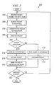
- FIGURE 2 is a flow chart 200 illustrating an example method of operation for IDS 102.
- IDS 102 receives a packet tagged for a first VLAN at step 202.
- IDS 102 buffer the packet at interface 108 at step 204.
- Interface 108 communicates a copy of the packet to processor 112 at step 206.
- Processor 112 analyzes the packet by comparing the packet to attack signatures 120 at step 208. If an attack signature is detected at decision step 210, then processor 112 sends an alert to interface 108 at step 212. Interface 108 then discards the packet from buffer 122 at step 214. If an attack signature is not detected, processor 112 sends an OK message to interface 108 at step 216. Interface 108 re-tags the packet with the identifier for the second VLAN associated with protected network 106 at step 218. Interface 108 then communicates the packet to protected network 106 at step 220. The method may be repeated as long as there are incoming packets, as shown by decision step 220.
Landscapes
- Engineering & Computer Science (AREA)
- Computer Security & Cryptography (AREA)
- Computer Hardware Design (AREA)
- Computing Systems (AREA)
- General Engineering & Computer Science (AREA)
- Computer Networks & Wireless Communication (AREA)
- Signal Processing (AREA)
- Data Exchanges In Wide-Area Networks (AREA)
Description
- The present invention relates generally to the field of network security, and more particularly to inline intrusion detection using a single physical port.
- Intrusion detection systems (IDSs) generally operate in one of two modes. In "promiscuous" mode, the IDS monitors incoming network traffic to determine whether a particular pattern characteristic of an intrusion can be observed. In "inline" mode, network traffic is scanned by the IDS to determine whether it contains a hostile signature. If a hostile signature is detected, the IDS prevents the network from receiving the traffic. Generally, inline IDSs have two physical ports, one coupled to the outside network and one coupled to the protected network. On the other hand, IDSs operating in promiscuous mode only need one physical port to receive network traffic.
-
US 2003/084326 discloses a method of identifying data comprised in a network exploit comprising receiving a packet by an intrusion prevention system maintained by a node of a network, the intrusion prevention system bound to a media access control driver and a protocol driver, invoking a signature analysis algorithm by the intrusion prevention system, and comparing the packet by the intrusion prevention system with a first rule set comprising a rule logically defining a packet signature is provided.US 2004/030927 discloses a method for processing data packets, which includes receiving the data packet, examining the data packet, determining a single flow record associated with the packet and extracting flow instructions for two or more devices from the single flow record. - In accordance with one embodiment of the present invention, a method for inline intrusion detection includes receiving a packet at a physical interface of an intrusion detection system. The packet is tagged with a first VLAN identifier associated with an external network. The network further includes buffering the packet at the physical interface, communicating a copy of the packet to a processor, and analyzing the copy of the packet at the processor to determine whether the packet includes an attack signature. The method also includes communicating a reply message from the processor to the interface indicating whether the packet includes an attack signature. If the packet does not contain an attack signature the buffered copy of the packet is re-tagged with a second VLAN identifier associated with a protected network and re-tagged packet is communicated to the protected network.
- In accordance with another embodiment of the present invention, an intrusion detection system includes an interface operable to receive a packet that is tagged with a first VLAN identifier associated with an external network. The interface is further operable to buffer the packet at the interface, communicate a copy of the packet to a processor, and re-tag the packet with a second VLAN identifier associated with a protected network. The intrusion detection system is also operable to communicate the packet to the protected network. The processor is operable to analyze the copy of the packet to determine if it includes an attack signature and communicate a reply message to the interface indicating whether the packet includes an attack signature. The interface re-tags and communicates the packet only if the reply message indicates that the packet does not include an attack signature.
- Important technical advantages of certain embodiments of the present invention include inline intrusion detection using a single port. This allows single-port intrusion detection systems that may have been used for monitoring to be adapted for use as inline systems. Furthermore, it may provide a lower cost alternative to multiple-port devices used for inline intrusion detection.
- Other important technical advantages of certain embodiments of the present invention include more efficient use of memory and bus resources in an inline system. Re-tagging packets with a VLAN identifier can be performed at the physical interface. Thus, in contrast with systems that operate at higher layers, such as firewalls, certain embodiments of the present invention allow a packet to be buffered and re-tagged without having to be processed and returned by a processor. This reduces the amount of packet communication between the interface and the processor.
- Additional technical advantages of the present invention will be readily apparent to one skilled in the art from the following figures, descriptions, and claims. Moreover, while specific advantages have been enumerated above, various embodiments may include all, some, or none of the enumerated advantages.
- For a more complete understanding of the present invention and its advantages, reference is now made to the following description, taken in conjunction with the accompanying drawings, in which:
-
FIGURE 1 illustrates an inline intrusion detection system using a single physical port; and -
FIGURE 2 illustrates a flow chart showing an example method of operation for the inline intrusion detection system ofFIGURE 1 . -
FIGURE 1 illustrates acomputer system 100 that includes an inline intrusion detection system (IDS) 102 between anexternal network 104 and a protectednetwork 106. Generally, IDS 102 receives information fromexternal network 104 and analyzes the information to determine whether the information includes a signature that is characteristic of a network attack or other hostile action. If an attack is detected, IDS 102 does not send the information to protectednetwork 106. Otherwise, IDS 102 communicates the information to protectednetwork 106. -
External network 104 may include any collection of networked communication devices exchanging information. Networked communication devices may include hubs, routers, switches, gateways, personal computers, telephones, or any other device that can exchange information. Devices inexternal network 104 may exchange information in the form of packets, cells, frames, segments, or other portions of data (collectively referred to as "packets").External network 104 may use any suitable medium or media of transmission, including wireline, wireless, or optical connections. Devices inexternal network 104 may communicate with one another using any number of suitable protocols, such as asynchronous transfer mode (ATM), transport control protocol / Internet protocol (TCP/IP), synchronous optical network (SONET), or Ethernet.External network 104 may also include the Internet. -
Protected network 106 represents any collection of communication devices communicating in any suitable manner. In particular, protectednetwork 106 may include any of the devices and communication media discussed in conjunction withexternal network 104.Protected network 106 may also use one or more suitable communication protocols, such as the ones described above. In particular,protected network 106 supports the use of virtual local area networks (VLANs). A VLAN is a logical separation created between devices that share a physical network, so that devices on one VLAN cannot communicate with one another using the existing physical connections between the devices except through suitable network bridging hardware and/or software. VLANs are described in IEEE specification 802.1q. -
Network gateway 105 represents any suitable hardware and/or software that communicates traffic received fromexternal network 106 to protectednetwork 106 and IDS 102. Traffic received fromexternal network 106 is automatically tagged with an identifier for a first VLAN.Protected network 106 is configured to be on a second VLAN, so that it does not recognize traffice tagged with the identifier of the first VLAN. Thus, even thoughnetwork gateway 105 may replicate the information to all of its ports, such as might take place in a network hub, the traffic will not be recognized by protectednetwork 106 unless tagged with the proper VLAN identifier.Network gateway 105 includes a monitoring port that replicates the contents of incoming network traffic for IDS 102. - IDS 102 is an inline security system that receives traffic from
external network 104, analyzes the traffic to determine if it contains an attack signature or other indication of hostile action, and prevents hostile information from reaching protectednetwork 106. In the depicted embodiment, IDS 102 includes aninterface 108, aprocessor 112, and a memory 114.Processor 112 may be any hardware and/or software components suitable for processing information, such as microprocessors, microcontrollers, or digital signal processors (DSPs). - Memory 114 is any suitable form of information storage, which may include magnetic media, optical media, removable media, local storage, remote storage, or other suitable component. In the depicted embodiment, memory 114
stores code 116,VLAN tags 118, andattack signatures 120.Code 116 is executed byprocessor 112 to perform any suitable task associated with IDS 102.VLAN tags 118 are stored identifiers associated respectively withexternal network 104 and protectednetwork 106.Attack signatures 120 are recognized patterns of information that indicate that an incoming packet represents a hostile action directed at protectednetwork 106.Processor 112 compares information to attacksignatures 120 to detect attacks. -
Interface 108 represents a physical connection allowing communication betweenIDS 102 and devices on protectednetwork 106 andexternal network 104. Communications withinterface 102 take place at layer 2 of the Open Systems Interconnect (OSI) model.Interface 108 supports VLAN trunking. VLAN trunking allowsinterface 108 to recognize and communicate with multiple VLANs, each identified by a particular VLAN tag.Interface 108 therefore effectively includes multiple logical ports, each associated with a particular VLAN.Interface 108 may tag packets and change existing tags appropriately so that a packet is communicated to a particular VLAN. - In the depicted embodiment,
interface 108 establishes a first VLAN forexternal network 104 and a second VLAN for protectednetwork 106. Thus,interface 108 has twological ports external network 104 is tagged with the VLAN tag associated with the first VLAN network, so it is not recognized by protectednetwork 106. Once the information is determined to be safe for protectednetwork 106,interface 106 may re-tag the information with the tag of the second VLAN. This effectively communicates information to protectednetwork 106 usinglogical port 110B, even thoughinterface 108 only includes one physical connection. -
Interface 108 also includes abuffer 122.Buffer 122 represents local information storage atinterface 108. Buffer 122 may include any suitable form of information storage, such as magnetic media, flash memory, optical media, or other type of information storage medium. Buffer 122 stores incoming information fromexternal network 104 while the information is processed by components ofIDS 102. In a particular embodiment,buffer 122 retains a copy of incoming traffic while the traffic is being analyzed byprocessor 112 to determine whether the incoming information is hostile. - In one example of a mode of operation,
network gateway 105 receives traffic from network and tags the traffic with a first VLAN identifier.Network gateway 105 may then broadcast the traffic to all of its ports or may communicate it toIDS 102 only. Protectednetwork 106 is configured to recognize only information on a second VLAN, so even if the packet is broadcast to protectednetwork 106, it will not be recognized.IDS 102 receives the traffic atinterface 108 and buffers the traffic inbuffer 122.IDS 102 communicates a copy of the packet toprocessor 112, which analyzes the traffic to determine whether it includes an attack signature.Processor 112 then returns a message toIDS 102 indicating whether the packet includes an attack signature or not. If the packet includes an attack signature, thenIDS 102 discards the packet frombuffer 112. Otherwise,IDS 102 may re-tag the packet with a second VLAN identifier and communicate the packet back tonetwork gateway 105, which in turn communicates the packet to protectednetwork 106. - One technical advantage of certain embodiments of the present invention is the opportunity to conserve memory and bus resources in
IDS 102. Since VLAN re-tagging may be performed atinterface 108,interface 108 does not require additional processing resources to move a packet from one VLAN to another. Conversely, network protection systems that operate at higher layers, such as firewalls, typically require network address translation or other similar adjustments to packet header information. Such systems must forward a packet to the appropriate processing resource using an internal bus, and then receive a returned packet suitably modified for communication to the network protected by these systems. In contrast to these conventional systems,interface 108 may receive a reply message, which may be as short as a single bit, that indicates whether or not the packet should be communicated to protectednetwork 106. Thus,IDS 102 may use less internal bus resources and also reduce the load ofbuffer 122, which need not store both incoming packets and packets returned byprocessor 112. -
FIGURE 2 is aflow chart 200 illustrating an example method of operation forIDS 102.IDS 102 receives a packet tagged for a first VLAN atstep 202.IDS 102 buffer the packet atinterface 108 atstep 204.Interface 108 communicates a copy of the packet toprocessor 112 atstep 206. -
Processor 112 analyzes the packet by comparing the packet to attacksignatures 120 atstep 208. If an attack signature is detected atdecision step 210, thenprocessor 112 sends an alert to interface 108 atstep 212.Interface 108 then discards the packet frombuffer 122 atstep 214. If an attack signature is not detected,processor 112 sends an OK message to interface 108 atstep 216. Interface 108 re-tags the packet with the identifier for the second VLAN associated with protectednetwork 106 atstep 218.Interface 108 then communicates the packet to protectednetwork 106 atstep 220. The method may be repeated as long as there are incoming packets, as shown bydecision step 220. - Although the present invention has been described with several embodiments, a myriad of changes, variations, alterations, transformations, and modifications may be suggested to one skilled in the art, and it is intended that the present invention encompass such changes, variations, alterations, transformations, and modifications as fall within the scope of the appended claims.
Claims (11)
- A method for inline intrusion detection, comprising:receiving (202) a packet at a physical interface of an intrusion detection system, wherein the packet is tagged with a first VLAN identifier associated with an external network;buffering (204) the packet at the physical interface;communicating (206) a copy of the packet to a processor;analyzing (208) the copy of the packet at the processor to determine whether the packet includes an attack signature;communicating a reply message from the processor to the interface indicating whether the packet includes an attack signature; andif the packet does not contain an attack signature:re-tagging (218) the buffered copy of the packet with a second VLAN identifier associated with a protected network; andcommunicating (220) the re-tagged packet to the protected network.
- The method of Claim 1, further comprising:receiving the packet from the external network at a network gateway;tagging the packet with the first VLAN identifier at the network gateway; andcommunicating the packet to the physical interface.
- The method of Claim 2, wherein the step of communicating the re-tagged packet to the protected network comprises:communicating the re-tagged packet to a first port of the network gateway; andcommunicating the re-tagged packet to the protected network using a second port of the network gateway.
- The method of Claim 2, wherein communicating the packet to the physical interface comprises:generating a copy of the packet for each of a plurality of ports of the network gateway, wherein one of the ports is coupled to the physical interface; andcommunicating one of the copies of the packet from each of the ports.
- The method of Claim 1, wherein the size of the reply message is less than the size of the packet.
- A computer-readable medium including executable instructions which, when executed in a processing system, cause the processing system to perform the steps of a method according to any preceding claim.
- A system, comprising:means for receiving a packet at a physical interface (108) of an intrusion detection system (102), wherein the packet is tagged with a first VLAN identifier associated with an external network (104);means (122) for buffering the packet at the physical interface (108);means for communicating a copy of the packet to a processor (112), wherein the processor (112) is operable to analyze the copy of the packet at the processor (112) to determine whether the packet includes an attack signature;means for communicating a reply message from the processor to the interface (108) indicating whether the packet includes an attack signature; andmeans for re-tagging the buffered copy of the packet with a second VLAN identifier associated with a protected network (106) if the packet does not contain an attack signature; andmeans for communicating the re-tagged packet to the protected network (106).
- The system of Claim 7, further comprising:means for receiving the packet from the external network at a network gateway;means for tagging the packet with the first VLAN identifier at the network gateway; andmeans for communicating the packet to the physical interface.
- The system of Claim 8, wherein:the means for communicating the re-tagged packet to the protected network is further operable to communicate the re-tagged packet to a first port of the network gateway; andthe network gateway is further operable to communicate the re-tagged packet to the protected network using a second port of the network gateway.
- The system of Claim 8, wherein the network gateway comprises:means for generating a copy of the packet for each of a plurality of ports of the network gateway, wherein one of the ports is coupled to the physical interface; andmeans for communicating one of the copies of the packet from each of the ports.
- The system of Claim 7, wherein the size of the reply message is less than the size of the packet.
Applications Claiming Priority (2)
| Application Number | Priority Date | Filing Date | Title |
|---|---|---|---|
| US10/910,194 US7555774B2 (en) | 2004-08-02 | 2004-08-02 | Inline intrusion detection using a single physical port |
| PCT/US2005/024592 WO2006019701A2 (en) | 2004-08-02 | 2005-07-12 | Inline intrusion detection using a single physical port |
Publications (3)
| Publication Number | Publication Date |
|---|---|
| EP1774716A2 EP1774716A2 (en) | 2007-04-18 |
| EP1774716A4 EP1774716A4 (en) | 2014-01-08 |
| EP1774716B1 true EP1774716B1 (en) | 2015-01-28 |
Family
ID=35732106
Family Applications (1)
| Application Number | Title | Priority Date | Filing Date |
|---|---|---|---|
| EP05773236.4A Active EP1774716B1 (en) | 2004-08-02 | 2005-07-12 | Inline intrusion detection using a single physical port |
Country Status (4)
| Country | Link |
|---|---|
| US (1) | US7555774B2 (en) |
| EP (1) | EP1774716B1 (en) |
| CN (1) | CN100477620C (en) |
| WO (1) | WO2006019701A2 (en) |
Families Citing this family (27)
| Publication number | Priority date | Publication date | Assignee | Title |
|---|---|---|---|---|
| WO2004114599A1 (en) * | 2003-06-20 | 2004-12-29 | Fujitsu Limited | Method for connecting devices in a network and network system using the same |
| US7562389B1 (en) | 2004-07-30 | 2009-07-14 | Cisco Technology, Inc. | Method and system for network security |
| US9407643B1 (en) * | 2004-08-03 | 2016-08-02 | Spirent Communications, Inc. | System and method for consolidating network streams for network analysis |
| US7561515B2 (en) * | 2004-09-27 | 2009-07-14 | Intel Corporation | Role-based network traffic-flow rate control |
| TW200612695A (en) * | 2004-10-08 | 2006-04-16 | Broad Web Corp | Content checking method applied to network packet of a network security switch |
| US7849506B1 (en) * | 2004-10-12 | 2010-12-07 | Avaya Inc. | Switching device, method, and computer program for efficient intrusion detection |
| US7602731B2 (en) * | 2004-12-22 | 2009-10-13 | Intruguard Devices, Inc. | System and method for integrated header, state, rate and content anomaly prevention with policy enforcement |
| US7626940B2 (en) * | 2004-12-22 | 2009-12-01 | Intruguard Devices, Inc. | System and method for integrated header, state, rate and content anomaly prevention for domain name service |
| US7725938B2 (en) * | 2005-01-20 | 2010-05-25 | Cisco Technology, Inc. | Inline intrusion detection |
| US8199754B2 (en) * | 2006-05-30 | 2012-06-12 | Hewlett-Packard Development Company, L. P. | Intrusion prevention system edge controller |
| US8176525B2 (en) * | 2006-09-29 | 2012-05-08 | Rockstar Bidco, L.P. | Method and system for trusted contextual communications |
| US8543667B2 (en) * | 2008-01-14 | 2013-09-24 | Akamai Technologies, Inc. | Policy-based content insertion |
| US8102783B1 (en) * | 2009-02-04 | 2012-01-24 | Juniper Networks, Inc. | Dynamic monitoring of network traffic |
| US8289981B1 (en) * | 2009-04-29 | 2012-10-16 | Trend Micro Incorporated | Apparatus and method for high-performance network content processing |
| WO2011053299A1 (en) * | 2009-10-29 | 2011-05-05 | Hewlett-Packard Development Company, L.P. | Switch that monitors for fingerprinted packets |
| JP5874146B2 (en) | 2010-06-18 | 2016-03-02 | アカマイ テクノロジーズ インコーポレイテッド | Extension of content distribution network (CDN) to mobile or wired networks |
| US9473518B2 (en) * | 2010-10-22 | 2016-10-18 | International Business Machines Corporation | Securing network communications with logical partitions |
| US9009782B2 (en) * | 2013-08-19 | 2015-04-14 | Freescale Semiconductor, Inc. | Steering traffic among multiple network services using a centralized dispatcher |
| CN105684378A (en) * | 2013-10-03 | 2016-06-15 | 迈克菲公司 | Duplicating packets efficiently within a network security appliance |
| US9973528B2 (en) | 2015-12-21 | 2018-05-15 | Fortinet, Inc. | Two-stage hash based logic for application layer distributed denial of service (DDoS) attack attribution |
| US10397186B2 (en) | 2017-10-06 | 2019-08-27 | Stealthpath, Inc. | Methods for internet communication security |
| US10375019B2 (en) | 2017-10-06 | 2019-08-06 | Stealthpath, Inc. | Methods for internet communication security |
| US10367811B2 (en) | 2017-10-06 | 2019-07-30 | Stealthpath, Inc. | Methods for internet communication security |
| US10630642B2 (en) | 2017-10-06 | 2020-04-21 | Stealthpath, Inc. | Methods for internet communication security |
| US10374803B2 (en) | 2017-10-06 | 2019-08-06 | Stealthpath, Inc. | Methods for internet communication security |
| US10361859B2 (en) | 2017-10-06 | 2019-07-23 | Stealthpath, Inc. | Methods for internet communication security |
| US11558423B2 (en) | 2019-09-27 | 2023-01-17 | Stealthpath, Inc. | Methods for zero trust security with high quality of service |
Family Cites Families (82)
| Publication number | Priority date | Publication date | Assignee | Title |
|---|---|---|---|---|
| US3974328A (en) | 1971-07-23 | 1976-08-10 | Martin Marietta Corporation | Line scan area signature detection system |
| US4103847A (en) | 1974-01-28 | 1978-08-01 | Martin Marietta Corporation | Line scan area signature detection method |
| US4286261A (en) | 1978-09-01 | 1981-08-25 | The United States Of America As Represented By The Secretary Of The Army | Apparatus for discriminating between strain and magnetic stimuli in magnetic cored solenoid type transducer line sensors |
| US4931740A (en) | 1988-08-02 | 1990-06-05 | Mcdonnell Douglas Corporation | Electrostatic field gradient sensor |
| US4991146A (en) | 1989-11-30 | 1991-02-05 | Deere & Company | Intrusion detection system |
| US5311510A (en) | 1991-07-30 | 1994-05-10 | The Furukawa Electric Co., Ltd. | Data storing system for a communication control circuit |
| US5963556A (en) | 1993-06-23 | 1999-10-05 | Digital Equipment Corporation | Device for partitioning ports of a bridge into groups of different virtual local area networks |
| US5557742A (en) | 1994-03-07 | 1996-09-17 | Haystack Labs, Inc. | Method and system for detecting intrusion into and misuse of a data processing system |
| US6584565B1 (en) | 1997-07-15 | 2003-06-24 | Hewlett-Packard Development Company, L.P. | Method and apparatus for long term verification of digital signatures |
| US6035405A (en) | 1997-12-22 | 2000-03-07 | Nortel Networks Corporation | Secure virtual LANs |
| US6279113B1 (en) * | 1998-03-16 | 2001-08-21 | Internet Tools, Inc. | Dynamic signature inspection-based network intrusion detection |
| US6477651B1 (en) | 1999-01-08 | 2002-11-05 | Cisco Technology, Inc. | Intrusion detection system and method having dynamically loaded signatures |
| US6487666B1 (en) | 1999-01-15 | 2002-11-26 | Cisco Technology, Inc. | Intrusion detection signature analysis using regular expressions and logical operators |
| US7107612B1 (en) | 1999-04-01 | 2006-09-12 | Juniper Networks, Inc. | Method, apparatus and computer program product for a network firewall |
| US7051365B1 (en) | 1999-06-30 | 2006-05-23 | At&T Corp. | Method and apparatus for a distributed firewall |
| US6826697B1 (en) | 1999-08-30 | 2004-11-30 | Symantec Corporation | System and method for detecting buffer overflow attacks |
| US6647400B1 (en) | 1999-08-30 | 2003-11-11 | Symantec Corporation | System and method for analyzing filesystems to detect intrusions |
| US6996843B1 (en) | 1999-08-30 | 2006-02-07 | Symantec Corporation | System and method for detecting computer intrusions |
| US7356841B2 (en) | 2000-05-12 | 2008-04-08 | Solutioninc Limited | Server and method for providing specific network services |
| US20020069356A1 (en) | 2000-06-12 | 2002-06-06 | Kwang Tae Kim | Integrated security gateway apparatus |
| AU2001288463A1 (en) | 2000-08-30 | 2002-03-13 | Citibank, N.A. | Method and system for internet hosting and security |
| US7032114B1 (en) | 2000-08-30 | 2006-04-18 | Symantec Corporation | System and method for using signatures to detect computer intrusions |
| GB0022485D0 (en) | 2000-09-13 | 2000-11-01 | Apl Financial Services Oversea | Monitoring network activity |
| US7120150B2 (en) | 2001-01-30 | 2006-10-10 | At & T Corp. | Technique for ethernet access to packet-based services |
| US7092389B2 (en) | 2001-01-30 | 2006-08-15 | At&T Corp. | Technique for ethernet access to packet-based services |
| US20020107961A1 (en) | 2001-02-07 | 2002-08-08 | Naoya Kinoshita | Secure internet communication system |
| US6957258B2 (en) | 2001-03-28 | 2005-10-18 | Netrake Corporation | Policy gateway |
| US7308715B2 (en) | 2001-06-13 | 2007-12-11 | Mcafee, Inc. | Protocol-parsing state machine and method of using same |
| US6928549B2 (en) | 2001-07-09 | 2005-08-09 | International Business Machines Corporation | Dynamic intrusion detection for computer systems |
| US7331061B1 (en) | 2001-09-07 | 2008-02-12 | Secureworks, Inc. | Integrated computer security management system and method |
| US7308714B2 (en) | 2001-09-27 | 2007-12-11 | International Business Machines Corporation | Limiting the output of alerts generated by an intrusion detection sensor during a denial of service attack |
| JP3879471B2 (en) | 2001-10-10 | 2007-02-14 | 株式会社日立製作所 | Computer resource allocation method |
| US20030084328A1 (en) | 2001-10-31 | 2003-05-01 | Tarquini Richard Paul | Method and computer-readable medium for integrating a decode engine with an intrusion detection system |
| US20030084344A1 (en) | 2001-10-31 | 2003-05-01 | Tarquini Richard Paul | Method and computer readable medium for suppressing execution of signature file directives during a network exploit |
| US20030084326A1 (en) | 2001-10-31 | 2003-05-01 | Richard Paul Tarquini | Method, node and computer readable medium for identifying data in a network exploit |
| US20030084318A1 (en) | 2001-10-31 | 2003-05-01 | Schertz Richard L. | System and method of graphically correlating data for an intrusion protection system |
| US7197762B2 (en) | 2001-10-31 | 2007-03-27 | Hewlett-Packard Development Company, L.P. | Method, computer readable medium, and node for a three-layered intrusion prevention system for detecting network exploits |
| US20030084321A1 (en) | 2001-10-31 | 2003-05-01 | Tarquini Richard Paul | Node and mobile device for a mobile telecommunications network providing intrusion detection |
| US7150043B2 (en) | 2001-12-12 | 2006-12-12 | International Business Machines Corporation | Intrusion detection method and signature table |
| US7222366B2 (en) | 2002-01-28 | 2007-05-22 | International Business Machines Corporation | Intrusion event filtering |
| US7076803B2 (en) | 2002-01-28 | 2006-07-11 | International Business Machines Corporation | Integrated intrusion detection services |
| US20030149887A1 (en) | 2002-02-01 | 2003-08-07 | Satyendra Yadav | Application-specific network intrusion detection |
| US7650634B2 (en) * | 2002-02-08 | 2010-01-19 | Juniper Networks, Inc. | Intelligent integrated network security device |
| US8370936B2 (en) * | 2002-02-08 | 2013-02-05 | Juniper Networks, Inc. | Multi-method gateway-based network security systems and methods |
| US7281269B1 (en) | 2002-03-06 | 2007-10-09 | Novell, Inc. | Methods, data structures, and systems to remotely validate a message |
| US7177295B1 (en) | 2002-03-08 | 2007-02-13 | Scientific Research Corporation | Wireless routing protocol for ad-hoc networks |
| US20030188190A1 (en) | 2002-03-26 | 2003-10-02 | Aaron Jeffrey A. | System and method of intrusion detection employing broad-scope monitoring |
| US6715084B2 (en) | 2002-03-26 | 2004-03-30 | Bellsouth Intellectual Property Corporation | Firewall system and method via feedback from broad-scope monitoring for intrusion detection |
| JP3917622B2 (en) | 2002-05-20 | 2007-05-23 | 富士通株式会社 | Network relay device, network relay method, network relay program |
| US20030236992A1 (en) | 2002-06-19 | 2003-12-25 | Sameer Yami | Method and system for providing secure logging for intrusion detection |
| US6950628B1 (en) | 2002-08-02 | 2005-09-27 | Cisco Technology, Inc. | Method for grouping 802.11 stations into authorized service sets to differentiate network access and services |
| US7711844B2 (en) | 2002-08-15 | 2010-05-04 | Washington University Of St. Louis | TCP-splitter: reliable packet monitoring methods and apparatus for high speed networks |
| US7152242B2 (en) | 2002-09-11 | 2006-12-19 | Enterasys Networks, Inc. | Modular system for detecting, filtering and providing notice about attack events associated with network security |
| US7716725B2 (en) | 2002-09-20 | 2010-05-11 | Fortinet, Inc. | Firewall interface configuration and processes to enable bi-directional VoIP traversal communications |
| US7062566B2 (en) | 2002-10-24 | 2006-06-13 | 3Com Corporation | System and method for using virtual local area network tags with a virtual private network |
| US7454499B2 (en) | 2002-11-07 | 2008-11-18 | Tippingpoint Technologies, Inc. | Active network defense system and method |
| US20050216770A1 (en) | 2003-01-24 | 2005-09-29 | Mistletoe Technologies, Inc. | Intrusion detection system |
| US6898632B2 (en) | 2003-03-31 | 2005-05-24 | Finisar Corporation | Network security tap for use with intrusion detection system |
| US20040221171A1 (en) | 2003-05-02 | 2004-11-04 | Ahmed Ahmed Awad E. | Intrusion detector based on mouse dynamics analysis |
| US20040255154A1 (en) | 2003-06-11 | 2004-12-16 | Foundry Networks, Inc. | Multiple tiered network security system, method and apparatus |
| US7712133B2 (en) | 2003-06-20 | 2010-05-04 | Hewlett-Packard Development Company, L.P. | Integrated intrusion detection system and method |
| US7392543B2 (en) | 2003-06-30 | 2008-06-24 | Symantec Corporation | Signature extraction system and method |
| US7463590B2 (en) * | 2003-07-25 | 2008-12-09 | Reflex Security, Inc. | System and method for threat detection and response |
| JP4123088B2 (en) | 2003-08-06 | 2008-07-23 | 株式会社日立製作所 | Storage network management apparatus and method |
| US7673147B2 (en) | 2003-09-26 | 2010-03-02 | Tizor Systems, Inc. | Real-time mitigation of data access insider intrusions |
| US7415719B2 (en) | 2003-09-26 | 2008-08-19 | Tizor Systems, Inc. | Policy specification framework for insider intrusions |
| US8880893B2 (en) | 2003-09-26 | 2014-11-04 | Ibm International Group B.V. | Enterprise information asset protection through insider attack specification, monitoring and mitigation |
| EP1668511B1 (en) | 2003-10-03 | 2014-04-30 | Enterasys Networks, Inc. | Apparatus and method for dynamic distribution of intrusion signatures |
| US7451483B2 (en) | 2003-10-09 | 2008-11-11 | International Business Machines Corporation | VLAN router with firewall supporting multiple security layers |
| US7310815B2 (en) | 2003-10-29 | 2007-12-18 | Sonicwall, Inc. | Method and apparatus for datastream analysis and blocking |
| BR0318587A (en) * | 2003-10-30 | 2006-10-17 | Telecom Italia Spa | Method and system for preventing intrusion into communication traffic with a set of machines on a network, telecommunications network, and computer program product |
| EP1542116A1 (en) | 2003-12-11 | 2005-06-15 | Alcatel | Access multiplexer with remote intrusion detection capability |
| US20050157653A1 (en) | 2004-01-16 | 2005-07-21 | Native Networks Technologies Ltd. | Method and device for charging for uncounted network traffic overhead |
| US20050193429A1 (en) * | 2004-01-23 | 2005-09-01 | The Barrier Group | Integrated data traffic monitoring system |
| US20050226257A1 (en) | 2004-03-30 | 2005-10-13 | Adc Broadband Access Systems, Inc. | Virtual local area network |
| US20050229246A1 (en) | 2004-03-31 | 2005-10-13 | Priya Rajagopal | Programmable context aware firewall with integrated intrusion detection system |
| US7706364B2 (en) | 2004-05-19 | 2010-04-27 | Cisco Technology, Inc. | Virtual network device clusters |
| US20050278178A1 (en) | 2004-06-10 | 2005-12-15 | International Business Machines Corporation | System and method for intrusion decision-making in autonomic computing environments |
| KR100604604B1 (en) | 2004-06-21 | 2006-07-24 | 엘지엔시스(주) | Method for securing system using server security solution and network security solution, and security system implementing the same |
| US7372841B2 (en) * | 2004-07-12 | 2008-05-13 | Research In Motion Limited | Packet-based communication system and method |
| KR100611741B1 (en) | 2004-10-19 | 2006-08-11 | 한국전자통신연구원 | Intrusion detection and prevention system and method thereof |
| US7725938B2 (en) * | 2005-01-20 | 2010-05-25 | Cisco Technology, Inc. | Inline intrusion detection |
-
2004
- 2004-08-02 US US10/910,194 patent/US7555774B2/en active Active
-
2005
- 2005-07-12 WO PCT/US2005/024592 patent/WO2006019701A2/en active Application Filing
- 2005-07-12 CN CN200580023142.9A patent/CN100477620C/en active Active
- 2005-07-12 EP EP05773236.4A patent/EP1774716B1/en active Active
Also Published As
| Publication number | Publication date |
|---|---|
| US7555774B2 (en) | 2009-06-30 |
| CN100477620C (en) | 2009-04-08 |
| EP1774716A2 (en) | 2007-04-18 |
| US20060023709A1 (en) | 2006-02-02 |
| EP1774716A4 (en) | 2014-01-08 |
| WO2006019701A2 (en) | 2006-02-23 |
| CN1985473A (en) | 2007-06-20 |
| WO2006019701A3 (en) | 2006-10-05 |
Similar Documents
| Publication | Publication Date | Title |
|---|---|---|
| EP1774716B1 (en) | Inline intrusion detection using a single physical port | |
| US7796515B2 (en) | Propagation of viruses through an information technology network | |
| US7725938B2 (en) | Inline intrusion detection | |
| US8045550B2 (en) | Packet tunneling | |
| US7706378B2 (en) | Method and apparatus for processing network packets | |
| US7499395B2 (en) | BFD rate-limiting and automatic session activation | |
| CN101589595B (en) | A containment mechanism for potentially contaminated end systems | |
| US7051369B1 (en) | System for monitoring network for cracker attack | |
| EP1873992B1 (en) | Packet classification in a network security device | |
| US8149705B2 (en) | Packet communications unit | |
| US7496055B2 (en) | Layer 2 loop detection system | |
| US7830898B2 (en) | Method and apparatus for inter-layer binding inspection | |
| EP2748981B1 (en) | Network environment separation | |
| EP2600566B1 (en) | Unauthorized access blocking control method | |
| CN102571738A (en) | Intrusion prevention system (IPS) based on virtual local area network (VLAN) exchange and system thereof | |
| US7562389B1 (en) | Method and system for network security | |
| US7437758B2 (en) | Propagation of viruses through an information technology network | |
| GB2403625A (en) | Distributing security updates to select nodes on a network | |
| AU2012202410B2 (en) | Method and apparatus for inspecting inter-layer address binding protocols | |
| Huang et al. | On the design of a cost effective network security switch architecture | |
| Cheng et al. | The dualgate Lock-Keeper: A highly efficient, flexible and applicable network security solution |
Legal Events
| Date | Code | Title | Description |
|---|---|---|---|
| PUAI | Public reference made under article 153(3) epc to a published international application that has entered the european phase |
Free format text: ORIGINAL CODE: 0009012 |
|
| 17P | Request for examination filed |
Effective date: 20070215 |
|
| AK | Designated contracting states |
Kind code of ref document: A2 Designated state(s): AT BE BG CH CY CZ DE DK EE ES FI FR GB GR HU IE IS IT LI LT LU LV MC NL PL PT RO SE SI SK TR |
|
| AX | Request for extension of the european patent |
Extension state: AL BA HR MK YU |
|
| DAX | Request for extension of the european patent (deleted) | ||
| A4 | Supplementary search report drawn up and despatched |
Effective date: 20131205 |
|
| RIC1 | Information provided on ipc code assigned before grant |
Ipc: H04L 29/06 20060101AFI20131129BHEP |
|
| REG | Reference to a national code |
Ref country code: DE Ref legal event code: R079 Ref document number: 602005045780 Country of ref document: DE Free format text: PREVIOUS MAIN CLASS: H04L0012280000 Ipc: H04L0029060000 |
|
| RIC1 | Information provided on ipc code assigned before grant |
Ipc: H04L 29/06 20060101AFI20140801BHEP |
|
| GRAP | Despatch of communication of intention to grant a patent |
Free format text: ORIGINAL CODE: EPIDOSNIGR1 |
|
| INTG | Intention to grant announced |
Effective date: 20140918 |
|
| RAP1 | Party data changed (applicant data changed or rights of an application transferred) |
Owner name: CISCO TECHNOLOGY, INC. |
|
| GRAS | Grant fee paid |
Free format text: ORIGINAL CODE: EPIDOSNIGR3 |
|
| GRAA | (expected) grant |
Free format text: ORIGINAL CODE: 0009210 |
|
| AK | Designated contracting states |
Kind code of ref document: B1 Designated state(s): AT BE BG CH CY CZ DE DK EE ES FI FR GB GR HU IE IS IT LI LT LU LV MC NL PL PT RO SE SI SK TR |
|
| REG | Reference to a national code |
Ref country code: GB Ref legal event code: FG4D |
|
| REG | Reference to a national code |
Ref country code: CH Ref legal event code: EP |
|
| REG | Reference to a national code |
Ref country code: IE Ref legal event code: FG4D |
|
| REG | Reference to a national code |
Ref country code: DE Ref legal event code: R096 Ref document number: 602005045780 Country of ref document: DE Effective date: 20150312 |
|
| REG | Reference to a national code |
Ref country code: AT Ref legal event code: REF Ref document number: 708651 Country of ref document: AT Kind code of ref document: T Effective date: 20150315 |
|
| REG | Reference to a national code |
Ref country code: AT Ref legal event code: MK05 Ref document number: 708651 Country of ref document: AT Kind code of ref document: T Effective date: 20150128 |
|
| REG | Reference to a national code |
Ref country code: NL Ref legal event code: VDEP Effective date: 20150128 |
|
| REG | Reference to a national code |
Ref country code: LT Ref legal event code: MG4D |
|
| REG | Reference to a national code |
Ref country code: FR Ref legal event code: PLFP Year of fee payment: 11 |
|
| PG25 | Lapsed in a contracting state [announced via postgrant information from national office to epo] |
Ref country code: BG Free format text: LAPSE BECAUSE OF FAILURE TO SUBMIT A TRANSLATION OF THE DESCRIPTION OR TO PAY THE FEE WITHIN THE PRESCRIBED TIME-LIMIT Effective date: 20150428 Ref country code: ES Free format text: LAPSE BECAUSE OF FAILURE TO SUBMIT A TRANSLATION OF THE DESCRIPTION OR TO PAY THE FEE WITHIN THE PRESCRIBED TIME-LIMIT Effective date: 20150128 Ref country code: FI Free format text: LAPSE BECAUSE OF FAILURE TO SUBMIT A TRANSLATION OF THE DESCRIPTION OR TO PAY THE FEE WITHIN THE PRESCRIBED TIME-LIMIT Effective date: 20150128 Ref country code: SE Free format text: LAPSE BECAUSE OF FAILURE TO SUBMIT A TRANSLATION OF THE DESCRIPTION OR TO PAY THE FEE WITHIN THE PRESCRIBED TIME-LIMIT Effective date: 20150128 Ref country code: LT Free format text: LAPSE BECAUSE OF FAILURE TO SUBMIT A TRANSLATION OF THE DESCRIPTION OR TO PAY THE FEE WITHIN THE PRESCRIBED TIME-LIMIT Effective date: 20150128 |
|
| PG25 | Lapsed in a contracting state [announced via postgrant information from national office to epo] |
Ref country code: PL Free format text: LAPSE BECAUSE OF FAILURE TO SUBMIT A TRANSLATION OF THE DESCRIPTION OR TO PAY THE FEE WITHIN THE PRESCRIBED TIME-LIMIT Effective date: 20150128 Ref country code: NL Free format text: LAPSE BECAUSE OF FAILURE TO SUBMIT A TRANSLATION OF THE DESCRIPTION OR TO PAY THE FEE WITHIN THE PRESCRIBED TIME-LIMIT Effective date: 20150128 Ref country code: LV Free format text: LAPSE BECAUSE OF FAILURE TO SUBMIT A TRANSLATION OF THE DESCRIPTION OR TO PAY THE FEE WITHIN THE PRESCRIBED TIME-LIMIT Effective date: 20150128 Ref country code: AT Free format text: LAPSE BECAUSE OF FAILURE TO SUBMIT A TRANSLATION OF THE DESCRIPTION OR TO PAY THE FEE WITHIN THE PRESCRIBED TIME-LIMIT Effective date: 20150128 Ref country code: GR Free format text: LAPSE BECAUSE OF FAILURE TO SUBMIT A TRANSLATION OF THE DESCRIPTION OR TO PAY THE FEE WITHIN THE PRESCRIBED TIME-LIMIT Effective date: 20150429 Ref country code: IS Free format text: LAPSE BECAUSE OF FAILURE TO SUBMIT A TRANSLATION OF THE DESCRIPTION OR TO PAY THE FEE WITHIN THE PRESCRIBED TIME-LIMIT Effective date: 20150528 |
|
| REG | Reference to a national code |
Ref country code: DE Ref legal event code: R097 Ref document number: 602005045780 Country of ref document: DE |
|
| PG25 | Lapsed in a contracting state [announced via postgrant information from national office to epo] |
Ref country code: EE Free format text: LAPSE BECAUSE OF FAILURE TO SUBMIT A TRANSLATION OF THE DESCRIPTION OR TO PAY THE FEE WITHIN THE PRESCRIBED TIME-LIMIT Effective date: 20150128 Ref country code: DK Free format text: LAPSE BECAUSE OF FAILURE TO SUBMIT A TRANSLATION OF THE DESCRIPTION OR TO PAY THE FEE WITHIN THE PRESCRIBED TIME-LIMIT Effective date: 20150128 Ref country code: RO Free format text: LAPSE BECAUSE OF FAILURE TO SUBMIT A TRANSLATION OF THE DESCRIPTION OR TO PAY THE FEE WITHIN THE PRESCRIBED TIME-LIMIT Effective date: 20150128 Ref country code: CZ Free format text: LAPSE BECAUSE OF FAILURE TO SUBMIT A TRANSLATION OF THE DESCRIPTION OR TO PAY THE FEE WITHIN THE PRESCRIBED TIME-LIMIT Effective date: 20150128 Ref country code: SK Free format text: LAPSE BECAUSE OF FAILURE TO SUBMIT A TRANSLATION OF THE DESCRIPTION OR TO PAY THE FEE WITHIN THE PRESCRIBED TIME-LIMIT Effective date: 20150128 |
|
| PLBE | No opposition filed within time limit |
Free format text: ORIGINAL CODE: 0009261 |
|
| STAA | Information on the status of an ep patent application or granted ep patent |
Free format text: STATUS: NO OPPOSITION FILED WITHIN TIME LIMIT |
|
| PG25 | Lapsed in a contracting state [announced via postgrant information from national office to epo] |
Ref country code: IT Free format text: LAPSE BECAUSE OF FAILURE TO SUBMIT A TRANSLATION OF THE DESCRIPTION OR TO PAY THE FEE WITHIN THE PRESCRIBED TIME-LIMIT Effective date: 20150128 |
|
| 26N | No opposition filed |
Effective date: 20151029 |
|
| PG25 | Lapsed in a contracting state [announced via postgrant information from national office to epo] |
Ref country code: MC Free format text: LAPSE BECAUSE OF FAILURE TO SUBMIT A TRANSLATION OF THE DESCRIPTION OR TO PAY THE FEE WITHIN THE PRESCRIBED TIME-LIMIT Effective date: 20150128 Ref country code: SI Free format text: LAPSE BECAUSE OF FAILURE TO SUBMIT A TRANSLATION OF THE DESCRIPTION OR TO PAY THE FEE WITHIN THE PRESCRIBED TIME-LIMIT Effective date: 20150128 |
|
| REG | Reference to a national code |
Ref country code: CH Ref legal event code: PL |
|
| PG25 | Lapsed in a contracting state [announced via postgrant information from national office to epo] |
Ref country code: LU Free format text: LAPSE BECAUSE OF FAILURE TO SUBMIT A TRANSLATION OF THE DESCRIPTION OR TO PAY THE FEE WITHIN THE PRESCRIBED TIME-LIMIT Effective date: 20150712 |
|
| REG | Reference to a national code |
Ref country code: IE Ref legal event code: MM4A |
|
| PG25 | Lapsed in a contracting state [announced via postgrant information from national office to epo] |
Ref country code: CH Free format text: LAPSE BECAUSE OF NON-PAYMENT OF DUE FEES Effective date: 20150731 Ref country code: LI Free format text: LAPSE BECAUSE OF NON-PAYMENT OF DUE FEES Effective date: 20150731 |
|
| PG25 | Lapsed in a contracting state [announced via postgrant information from national office to epo] |
Ref country code: BE Free format text: LAPSE BECAUSE OF FAILURE TO SUBMIT A TRANSLATION OF THE DESCRIPTION OR TO PAY THE FEE WITHIN THE PRESCRIBED TIME-LIMIT Effective date: 20150128 |
|
| REG | Reference to a national code |
Ref country code: FR Ref legal event code: PLFP Year of fee payment: 12 |
|
| PG25 | Lapsed in a contracting state [announced via postgrant information from national office to epo] |
Ref country code: IE Free format text: LAPSE BECAUSE OF NON-PAYMENT OF DUE FEES Effective date: 20150712 |
|
| PG25 | Lapsed in a contracting state [announced via postgrant information from national office to epo] |
Ref country code: HU Free format text: LAPSE BECAUSE OF FAILURE TO SUBMIT A TRANSLATION OF THE DESCRIPTION OR TO PAY THE FEE WITHIN THE PRESCRIBED TIME-LIMIT; INVALID AB INITIO Effective date: 20050712 |
|
| PG25 | Lapsed in a contracting state [announced via postgrant information from national office to epo] |
Ref country code: CY Free format text: LAPSE BECAUSE OF FAILURE TO SUBMIT A TRANSLATION OF THE DESCRIPTION OR TO PAY THE FEE WITHIN THE PRESCRIBED TIME-LIMIT Effective date: 20150128 |
|
| REG | Reference to a national code |
Ref country code: FR Ref legal event code: PLFP Year of fee payment: 13 |
|
| PG25 | Lapsed in a contracting state [announced via postgrant information from national office to epo] |
Ref country code: TR Free format text: LAPSE BECAUSE OF FAILURE TO SUBMIT A TRANSLATION OF THE DESCRIPTION OR TO PAY THE FEE WITHIN THE PRESCRIBED TIME-LIMIT Effective date: 20150128 |
|
| PG25 | Lapsed in a contracting state [announced via postgrant information from national office to epo] |
Ref country code: PT Free format text: LAPSE BECAUSE OF FAILURE TO SUBMIT A TRANSLATION OF THE DESCRIPTION OR TO PAY THE FEE WITHIN THE PRESCRIBED TIME-LIMIT Effective date: 20150128 |
|
| REG | Reference to a national code |
Ref country code: FR Ref legal event code: PLFP Year of fee payment: 14 |
|
| REG | Reference to a national code |
Ref country code: DE Ref legal event code: R079 Ref document number: 602005045780 Country of ref document: DE Free format text: PREVIOUS MAIN CLASS: H04L0029060000 Ipc: H04L0065000000 |
|
| P01 | Opt-out of the competence of the unified patent court (upc) registered |
Effective date: 20230525 |
|
| PGFP | Annual fee paid to national office [announced via postgrant information from national office to epo] |
Ref country code: GB Payment date: 20230726 Year of fee payment: 19 |
|
| PGFP | Annual fee paid to national office [announced via postgrant information from national office to epo] |
Ref country code: FR Payment date: 20230727 Year of fee payment: 19 Ref country code: DE Payment date: 20230728 Year of fee payment: 19 |