EP1774284B1 - Methods and apparatus for the separation and quantification of particles - Google Patents
Methods and apparatus for the separation and quantification of particles Download PDFInfo
- Publication number
- EP1774284B1 EP1774284B1 EP05769800.3A EP05769800A EP1774284B1 EP 1774284 B1 EP1774284 B1 EP 1774284B1 EP 05769800 A EP05769800 A EP 05769800A EP 1774284 B1 EP1774284 B1 EP 1774284B1
- Authority
- EP
- European Patent Office
- Prior art keywords
- particles
- point
- electrodes
- sep2
- sep1
- Prior art date
- Legal status (The legal status is an assumption and is not a legal conclusion. Google has not performed a legal analysis and makes no representation as to the accuracy of the status listed.)
- Expired - Lifetime
Links
Images

Classifications
-
- G—PHYSICS
- G01—MEASURING; TESTING
- G01N—INVESTIGATING OR ANALYSING MATERIALS BY DETERMINING THEIR CHEMICAL OR PHYSICAL PROPERTIES
- G01N15/00—Investigating characteristics of particles; Investigating permeability, pore-volume or surface-area of porous materials
- G01N15/10—Investigating individual particles
-
- B—PERFORMING OPERATIONS; TRANSPORTING
- B03—SEPARATION OF SOLID MATERIALS USING LIQUIDS OR USING PNEUMATIC TABLES OR JIGS; MAGNETIC OR ELECTROSTATIC SEPARATION OF SOLID MATERIALS FROM SOLID MATERIALS OR FLUIDS; SEPARATION BY HIGH-VOLTAGE ELECTRIC FIELDS
- B03C—MAGNETIC OR ELECTROSTATIC SEPARATION OF SOLID MATERIALS FROM SOLID MATERIALS OR FLUIDS; SEPARATION BY HIGH-VOLTAGE ELECTRIC FIELDS
- B03C5/00—Separating dispersed particles from liquids by electrostatic effect
- B03C5/02—Separators
- B03C5/022—Non-uniform field separators
- B03C5/026—Non-uniform field separators using open-gradient differential dielectric separation, i.e. using electrodes of special shapes for non-uniform field creation, e.g. Fluid Integrated Circuit [FIC]
-
- G—PHYSICS
- G01—MEASURING; TESTING
- G01N—INVESTIGATING OR ANALYSING MATERIALS BY DETERMINING THEIR CHEMICAL OR PHYSICAL PROPERTIES
- G01N15/00—Investigating characteristics of particles; Investigating permeability, pore-volume or surface-area of porous materials
- G01N15/02—Investigating particle size or size distribution
Landscapes
- Chemical & Material Sciences (AREA)
- Life Sciences & Earth Sciences (AREA)
- Biochemistry (AREA)
- Dispersion Chemistry (AREA)
- Physics & Mathematics (AREA)
- Health & Medical Sciences (AREA)
- Pathology (AREA)
- Analytical Chemistry (AREA)
- Immunology (AREA)
- General Health & Medical Sciences (AREA)
- General Physics & Mathematics (AREA)
- Microelectronics & Electronic Packaging (AREA)
- Engineering & Computer Science (AREA)
- Electrostatic Separation (AREA)
- Investigating Or Analyzing Materials By The Use Of Electric Means (AREA)
Description
- This invention pertains to methods and apparatuses to separate particles with different physical properties, and/or to measure the quantity or size of particles. The invention mainly finds application in the analysis and separation of biological samples.
- The patent application
PCT/WO 00/69565 to G. Medoro PCT/WO 00/69565 - Many other methods of separation are known that nevertheless require using flows of liquid, which is an undesirable characteristic in many applications, since it requires generating well controlled flows. A review of these methods, above all as concerns the use of dielectrophoresis is given in Electrophoresis 2002, 23, 2569-2582 M. P. Hughes , and in Electrophoresis 2002, 23, 1973-1983 P.R.C. Gascoyne, J. Vykoukal , and in the related bibliographical references.
- In particular, the patent
US 5,888,370 to Becker et al. teaches among other things to use dielectrophoresis to determine the height of particles in a speed-profile of liquid flow, to which the separation of the particles follows. - OHARA T et Al. "Ratcheting electrophoresis microchip (REM) for programmable transport and separation of macromolecules", Proceedings of the International Mechanical Engineering Congress and Exposition - IMECE - ASME, vol. 3, 11 November 2001 (2001-11-11), pages 619-628 does not allow a reliable control. Other methods of separation based on dielectrophoresis do not require using flows of liquid, but they utilize so-called Travelling waves (TWD). These methods are based on the application to an array of electrodes of sinusoidal voltages at suitably phase-shifted radio frequencies (e.g. 0, 90, 180, 270 degrees). The result is an electric field that travels in space at a speed (VTW) equal to the distance between the electrodes with the same phase divided by the period of the single sine voltage. The phase-shift between the polarization induced on the particle and the electric field that generates it causes a translation of the particle, at a speed of orders of magnitude less than VTW, and asynchronous with it. Accordingly it is not possible to maintain an accurate control on the position of the particles after separation, which may be desirable in many applications, for instance if it is wished to determine the quantity of separated particles by placing them above sensors.
- The limitations of the known art are superseded by this invention that permits separating particles even if they are subject to the same force (e.g. NDEP), it requires no flow of liquid, and it permits keeping a control on the position of the particles during and after separation or measurement.
- The invention pertains to non-uniform force fields. The force fields can be for dielectrophoresis (positive or negative), electrophoresis or electrohydrodynamic motion, characterized by a set of stable-equilibrium methods according to respective claims 1-2, and to a corresponding apparatus according to claim 8.
- Hereinafter, the term particles will be used to indicate micrometric or nanometric, natural or artificial entities, such as cells, subcellular components, viruses, liposomes, niosomes, microbeads and nanobeads, or even smaller entities such as macro-molecules, proteins, DNA, RNA, etc, as well as drops of liquid immiscible in the suspension medium, for example oil in water or water in oil.
-
-
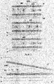
Fig 1 shows the principle of generation of the force field by means of an array of electrodes. -
Fig, 2 shows some experimental data and simulations of speed of translation of microbeads of polystyrene. -
Fig. 3 shows the principle of separation by means of only two groups of stable equilibrium points. -
Fig. 4 shows a device to bring about the method of separation by means of only two groups of points of stable equilibrium. - The purpose of the invention is to create a method and an apparatus for the separation of particles according to their physical properties or their quantification or the determination of their size. The method is based on using a non-uniform force field (F). This field can for instance be a field of dielectrophoresis (DEP) negative (NDEP) or positive (PDEP), an electrophoretic field (EF) or a field of electrohydrodynamic motion (EHD).
-
Fig. 1 shows some methods of generating the force field, according to the known art, using an array of electrodes (EL), made on at least one substrate (SUB, SUB2). A cover (LID), that can in its turn be an electrode, bounds a micro-chamber, in use filled with a liquid havin a certain viscosity. In the case of DEP, the applied voltages are periodic voltages (preferably sinusoidal) in phase (+) and counter-phase (-). Voltages in counter-phase are understood to be voltages phase-shifted by 180 degrees. The field generates a force (F) that acts both on faster particles (FP) and on slower particles (SP), both attracted toward points of equilibrium (PEQ). Depending on the configuration of the voltages applied it is possible to identify coordinates (DEPC) corresponding to the position of the point of stable equilibrium (PEQ), and coordinates (WS) corresponding to points of unstable equilibrium, that is to the boundary of the basin of attraction of different stable-equilibrium points. These lines ideally form a sort of watershed that determines toward which point of stable equilibrium the particle tends to go. In the case of negative DEP (NDEP), it is possible to make closed force cages if the cover (LID) is a conductive electrode. The point of equilibrium (PEQ) is normally found in the liquid at a certain height compared to the electrodes, so that the particles (SP, FP) are, in steady-state, in levitation. In the case of positive DEP (PDEP), the point of equilibrium (PEQ) is normally found in correspondence with the surface on which the electrodes are made, and the particles (FP, SP) are, in steady-state, in contact with it. For PDEP it is not necessary to have additional electrodes in the cover because the points of equilibrium of the PDEP correspond to maxima of the electric field. - The field can have a spatial periodicity (CPIT) that is a multiple of the periodicity of the electrodes (EPIT), in the cases in which this can be defined.
- When the points of stable equilibrium of the force field (F) are moved by a step (EPIT) changing the configuration of the voltages (+, -) applied to the electrodes (EL), the particles converge toward the new point of equilibrium with a time that substantially depends on the ratio between the force of viscous friction and the force of the field (F).
Fig. 2 shows some experimental data and simulations of the necessary time to complete a movement equal to half an EPIT step following the movement of the points of equilibrium of the force field of an EPIT step (in the specific case equal to 25 µm), for microbeads of polystyrene subject to NDEP, respectively 3µm and 10µm in diameter, depending on the peak-to-peak amplitude of the sine voltage applied to the electrodes. For the same particle material, the force of the field (F) is proportional to the volume, that is to the cube of the radius, while the viscous force is proportional to the radius, so particles with a greater radius will move faster (FP) than those of smaller diameter (SP). This effect is exploited, in accordance with the invention, to separate the particles or quantify groups of particles or to determine the size of such particles, as described hereunder. It is evident to experts in the sector with ordinary abilities that the difference in speed can also occur for particles of the same diameter (same force of viscous friction), on which the force field (F) acts with different intensity. In this case the particles on which it acts with greater intensity (FP) are faster than those on which it acts with less intensity (SP). - It is moreover evident that the method is also effectively applied in cases in which the field acts with the same force on all the particles, but the viscous friction is different due, e.g. to the different material or shape of the particles.
- The principle of the separation exploits the balancing between a force generated by the field (F), not uniform in the space and that moves in a controlled manner, and a force that acts uniformly. This can be the viscous friction, as described above, but also, for example, the force of gravity. For example, two particles on which the field (F) acts with the same force and that have the same viscous friction (for instance having the same diameter) would nevertheless be able to have different mass. In this case, tilting the device so that the force of gravity has a non-null component in the direction of movement of the force field (F) will cause the particles to have a different speed, so that it is anyhow possible to apply the method. In general, one different physical property between the particles is enough to permit separation. The physical properties according to which the particles are discriminated can for instance be the diameter, shape, material of which they are made or the relative proportion and the arrangement of the component materials, or even the surface properties. In other cases they can include the electric charge. They can obviously also be combinations of the aforesaid properties. By way of example, but without restricting the purpose of the invention we can mention the separation of:
- cells of the same type but of different dimensions;
- cells of the same type but with different functional properties;
- ∘ sperm cells with morphological anomalies from normal sperm cells;
- cells of the same dimensions but with a different composition of the cytoplasm;
- apoptotic cells from vital cells;
- cells infected with viruses or intracellular parasites from non-infected cells;
- ∘ cells infected with AIDS from non-infected cells;
- ∘ cells infected with malaria from non-infected cells;
- ∘ cells infected with Chlamydia from non-infected cells;
- cells decorated with antibodies from non-decorated cells;
- cells of different types:
- ∘ red blood cells from lymphocytes;
- ∘ red blood cells from erythromyeloid cells;
- ∘ sperm cells from vaginal epithelial cells;
- liposomes of different dimensions but with the same content;
- microbeads of different dimensions;
- ∘ polystyrene beads of 3µm and 10µm;
- ∘ beads of 6µm and 15µm;
- microbeads of the same dimensions but with different surface functionalities:
- ∘ beads of 3µm functionalized with ammine groups and non-functionalized beads;
- microbeads of the same dimensions but with different surface charge;
- positively charged microbeads from neutral microbeads;
- cells from viruses
- viruses of different types
- fragments of DNA of different molecular weight;
- proteins with a different ratio between mass and charge.
- In the above examples we have considered a regular array of electrodes, of equal width, with spatial periodicity EPIT. An aspect of the method according to the invention covers the case in which the array of electrodes is irregular. For example, it is possible to use electrodes of fixed dimensions but with a variable distance between the electrodes, or electrodes of varying dimensions with the same distance between the electrodes or variable dimensions both in their width and for the distance between the electrodes.
- In these cases, besides varying the position of the points of equilibrium of the force field, its intensity varies during the translation, and in general the shape of the field also varies, that is the lines of force are not only translated but distorted too.
- By exploiting the non-homogeneity of the field, particles of different diameter can be separated by pushing them both toward the same direction until the field deforms so much as to no longer be able to transport just one of the two types of particles. It is moreover evident that the same method of separation can be applied to the generic case of the separation of more than two types of particles.
- In the above examples we have considered a succession of configurations of forces in the space; the minimum number of configurations of forces, necessary to permit the movement of particles in a specific direction and therefore their separation, is two. Indeed, as shown in Fig. 14, it is possible with an appropriate distribution of electrodes and applied voltages (V1,V2) to make just two distributions of forces (F1, F2) characterized by groups of points of stable equilibrium (GSEP1, GSEP2) such that any first point of equilibrium (SEP1, SEP2) of one of said groups (GSEP1, GSEP2) is unequivocally included inside the basin of attraction of a single second point of stable equilibrium (SEP2, SEP1) of the other group (GSEP2, GSEP1), and that said second point in its turn is not contained in the basin of attraction of said first point (SEP1, SEP2); in this way passing from one configuration of forces to the following one, the particles are moved in a specific direction; returning to the previous configuration of forces, however, the particles do not reverse the motion but continue in the same direction. By alternating the two configurations of forces at an appropriate speed, it is possible to move the more responsive particles (FP) leaving the less responsive ones (SP) stationary or behind.
- This method requires both a spatial non-homogeneity and a spatial non-repeatability of the field; this can be obtained, for example, by means of the apparatus subject of the invention as described in detail hereunder.
- According to this method it is possible to separate particles of at least two types (FP, SP), so as to obtain a net movement of only said particles of a first type (FP) by changing the configuration of the field of forces at a frequency substantially comparable to the inverse of the settling-time of the particles of a first type (FP) at the new point of equilibrium, but greater than the inverse of the settling-time of the particles of at least a second type (SP). According to this method it is also possible to separate particles of at least two sizes (BP, LP). In fact, when a particle (BP) is much bigger than the basin of attraction of a stable equilibrium point, so that it is subject to the attraction of more than one point of equilibrium, the particle does not move, since the resultant of forces is not enough to propel the particle (BP) toward either of the equilibrium points. Hence, to carry out the separation of small particles (LP) one can generate a first distribution in the space of a force field (F1) characterized by a first set of points of stable equilibrium (GSEP1) for said particles (BP, LP); and at least a second distribution in the space of a force field (F2) characterized by a second set of points of stable equilibrium (GSEP2) for said particles (BP, LP); wherein said two distributions of forces (F1, F2) are such that any first point of equilibrium (SEP1, SEP2) of one of said groups (GSEP1, GSEP2) is unequivocally included inside the basin of attraction of a single second point of stable equilibrium (SEP2, SEP1) of the other group (GSEP2, GSEP1), and that said second point in its turn is not contained in the basin of attraction of said first point (SEP1, SEP2); and that the size of the basin of attraction of each first point (SEP1, SEP2) is greater or less than the size of the basin of attraction of said single second point of stable equilibrium (SEP2, SEP1) containing it;; and then can alternate the distributions (F1, F2) of said force field at a frequency comparable to the inverse of the settling-time of both types of particles (BP, LP), so as to move said particles (BP, LP) from one new point of equilibrium to the next one as long as the size of the particles is compatible with that of the basin of attraction. As the size of the basins of attraction gradually reduces, the big particles (BP) will in fact stop moving earlier than the small particles (LP), so as to obtain a net overall movement of the small particles (LP) greater than the net overall movement of the large particles (BP).
- The subject of this invention is also an apparatus to make appropriate field configurations that are necessary for the selective movement of particles; this device, in one of its typical implementations, has two array of electrodes (EL1, EL2) and, if necessary, a cover (LID); means to apply an electric potential (V1) to said first array of electrodes (EL1) and at least a second potential (V2) to said at least a second array of electrodes (EL2) are also included even if not shown because substantially of know kind; said electrodes and said means to apply an electric potential to said electrodes are operatively associated such that on the electrodes (EL1, EL2) appropriate stimuli (VI, V2) are applied to make at least two different spatial distributions of forces (F1, F2), each characterized by a group of points of stable equilibrium (SEP1, SEP2). A characteristic of these points of stable equilibrium is that each one is unequivocally included in just one of the basins of attraction of the stable-equilibrium points of the other configuration of forces. In this way the device subject of the invention permits trapping particles and moving them in a direction at a speed that depends on the speed with which the two configurations of forces are alternated and on the responsiveness of the particles. These distributions of forces can be made, for example, by utilizing electrodes of increasing or decreasing width and constant inter-electrode distance (
Fig. 3 ) or with an increasing or decreasing inter-electrode distance and constant width. Another implementation can be based on the use of electrodes of constant dimensions and constant inter-electrode distance but with an increasing or decreasing distance between the electrodes and the cover (Fig. 4 ). A combination of the above-described implementations is obviously possible.
Claims (11)
- A method to separate particles of at least two types (FP, SP), comprising steps of:i. generating a first distribution in space of a force field (F1) characterized by a first set (GSEP1) of points (SEP1) of stable equilibrium for the particles (FP, SP);ii. generating a second distribution in space of a force field (F2) characterized by a second set (GSEP2) of points (SEP2) of stable equilibrium for the particles (FP, SP);wherein said two distributions of forces (F1, F2) are such that any first point of equilibrium (SEP1, SEP2) of one of said sets (GSEP1, GSEP2) is unequivocally included inside the basin of attraction of a single second point of stable equilibrium (SEP2, SEP1) of the other set (GSEP2, GSEP1), and that said second point in its turn is not contained in the basin of attraction of said first point (SEP1, SEP2);;iii. alternating said distributions of forces (F1, F2) by changing the configuration of the field of forces at a frequency substantially comparable to the inverse of the settling-time of the particles of a first type (FP) at the new point of equilibrium, but greater than the inverse of the settling-time of the particles of at least a second type (SP);so as to obtain a net movement of only said particles of a first type (FP).
- A method to separate particles of at least two sizes (BP, LP), comprising steps of:i. generating a first distribution in space of a force field (F1) characterized by a first set of points of stable equilibrium (GSEP1) for said particles (BP, LP);ii. generating a second distribution in space of a force field (F2) characterized by a second set of points of stable equilibrium (GSEP2) for said particles (BP, LP);wherein said two distributions of forces (F1, F2) are such that any first point of equilibrium (SEP1, SEP2) of one of said sets (GSEP1, GSEP2) is unequivocally included inside the basin of attraction of a single second point of stable equilibrium (SEP2, SEP1) of the other set (GSEP2, GSEP1), and that said second point in its turn is not contained in the basin of attraction of said first point (SEP1, SEP2); and that the size of the basin of attraction of each first point (SEP1, SEP2) is greater than the size of the basin of attraction of said single second point of stable equilibrium (SEP2, SEP1) containing the first point.iii. alternating the distributions of forces (F1, F2) at a frequency comparable to the inverse of the settling-time of both types of particles (BP, LP), so as to move said particles (BP, LP) from one new point of equilibrium to the next one as long as the size of the particles is compatible with that of the basin of attraction;so as to obtain a net overall movement of the small particles (LP) greater than the net overall movement of the large particles (BP).
- A method as in claim 1 or 2, characterized by the fact that said sets of points of stable equilibrium (GSEP1, GSEP2) are generated by at least one non-homogeneous set of electrodes (EL) distributed with a constant step of spatial repetition.
- A method as in claim 1 or 2, characterized by the fact that said sets of points of stable equilibrium (GSEP1, GSEP2) are generated by at least one homogeneous set of electrodes (EL) distributed with a non-constant step of spatial repetition.
- A method as in claim 1 or 2, characterized by the fact that said sets of points of stable equilibrium (SEP1, SEP2) are generated by at least one non-homogeneous set of electrodes (EL) distributed with a non-constant step of spatial repetition.
- A method as in claim 1 or 2, characterized by the fact that said sets of points of stable equilibrium (SEP1, SEP2) are generated by at least one homogeneous set of electrodes (EL) distributed with a constant step of spatial repetition, supplied with voltages of non-constant amplitude.
- A method as in one of the claims 3, 4, 5 or 6, characterized by the fact that said sets of points of stable equilibrium (SEP1, SEP2) are generated by said array of electrodes (EL) and by at least one electrode (LID) facing and angled to said array of electrodes (EL).
- An apparatus for performing the method of claim 1 or 2, comprising:i. a number of arrays of at least one electrode, composed of a first array of electrodes (EL1) and at least a second array of electrodes (EL2);ii. means to apply an electric potential (V1) to said first array of electrodes (EL1) and at least a second potential (V2) to said at least a second array of electrodes (EL2);wherein said electrodes and said means to apply an electric potential to said electrodes are operatively associated such as to be able to- generate a first distribution in space of a force field (F1) characterized by a first set of points of stable equilibrium (GSEP1) for said particles;- generate a second distribution in space of a force field (F2) characterized by a second set of points of stable equilibrium (GSEP2) for said particles;
wherein said two distributions of forces (F1, F2) are such that any first point of equilibrium (SEP1, SEP2) of one of said sets (GSEP1, GSEP2) is unequivocally included inside the basin of attraction of a single second point of stable equilibrium (SEP2, SEP1) of the other set (GSEP2, GSEP1), and that said second point in its turn is not contained in the basin of attraction of said first point (SEP1, SEP2);- alternate the distributions of forces (F1, F2) at the said frequency;and wherein the size of the basin of attraction of each first point (SEP1, SEP2) is greater than the size of the basin of attraction of said single second point of stable equilibrium (SEP2, SEP1) containing the first point. - An apparatus as in claim 8, characterized by the fact that said arrays (EL1, EL2) are composed of electrodes distributed with a non-constant step of spatial repetition.
- An apparatus as in claim 8, characterized by the fact that said arrays (EL1, EL2) are composed of electrodes distributed on a substrate (SUB) with a constant step of spatial repetition and a cover facing and angled to said substrate (SUB).
- An apparatus as in claim 8, characterized by the fact that said electrodes of said number of arrays are distributed with a constant step of spatial repetition and that said means to apply an electric potential to said electrodes are such to generate potentials having an increasing or decreasing amplitude.
Priority Applications (1)
| Application Number | Priority Date | Filing Date | Title |
|---|---|---|---|
| EP12177401.2A EP2540399B1 (en) | 2004-07-07 | 2005-07-06 | Methods for the separation and quantification of particles |
Applications Claiming Priority (2)
| Application Number | Priority Date | Filing Date | Title |
|---|---|---|---|
| IT000420A ITBO20040420A1 (en) | 2004-07-07 | 2004-07-07 | METAL CUTTING AND FORMING MACHINE |
| PCT/EP2005/053235 WO2006003214A2 (en) | 2004-07-07 | 2005-07-06 | Method and apparatus for the separation and quantification of particles |
Related Child Applications (2)
| Application Number | Title | Priority Date | Filing Date |
|---|---|---|---|
| EP12177401.2A Division-Into EP2540399B1 (en) | 2004-07-07 | 2005-07-06 | Methods for the separation and quantification of particles |
| EP12177401.2A Division EP2540399B1 (en) | 2004-07-07 | 2005-07-06 | Methods for the separation and quantification of particles |
Publications (2)
| Publication Number | Publication Date |
|---|---|
| EP1774284A2 EP1774284A2 (en) | 2007-04-18 |
| EP1774284B1 true EP1774284B1 (en) | 2018-05-02 |
Family
ID=35219711
Family Applications (2)
| Application Number | Title | Priority Date | Filing Date |
|---|---|---|---|
| EP05769800.3A Expired - Lifetime EP1774284B1 (en) | 2004-07-07 | 2005-07-06 | Methods and apparatus for the separation and quantification of particles |
| EP12177401.2A Expired - Lifetime EP2540399B1 (en) | 2004-07-07 | 2005-07-06 | Methods for the separation and quantification of particles |
Family Applications After (1)
| Application Number | Title | Priority Date | Filing Date |
|---|---|---|---|
| EP12177401.2A Expired - Lifetime EP2540399B1 (en) | 2004-07-07 | 2005-07-06 | Methods for the separation and quantification of particles |
Country Status (10)
| Country | Link |
|---|---|
| US (2) | US8685217B2 (en) |
| EP (2) | EP1774284B1 (en) |
| JP (2) | JP5042822B2 (en) |
| CN (1) | CN101076717B (en) |
| CA (2) | CA2849632C (en) |
| DK (1) | DK1774284T3 (en) |
| ES (2) | ES2675325T3 (en) |
| IT (1) | ITBO20040420A1 (en) |
| PT (1) | PT1774284T (en) |
| WO (1) | WO2006003214A2 (en) |
Families Citing this family (20)
| Publication number | Priority date | Publication date | Assignee | Title |
|---|---|---|---|---|
| ITBO20040420A1 (en) | 2004-07-07 | 2004-10-07 | Type S R L | METAL CUTTING AND FORMING MACHINE |
| ITBO20050481A1 (en) | 2005-07-19 | 2007-01-20 | Silicon Biosystems S R L | METHOD AND APPARATUS FOR THE HANDLING AND / OR IDENTIFICATION OF PARTICLES |
| ITBO20050646A1 (en) | 2005-10-26 | 2007-04-27 | Silicon Biosystem S R L | METHOD AND APPARATUS FOR CHARACTERIZATION AND COUNTING OF PARTICLES |
| ITTO20060226A1 (en) | 2006-03-27 | 2007-09-28 | Silicon Biosystem S P A | METHOD AND APPARATUS FOR PROCESSING AND OR ANALYSIS AND OR SELECTION OF PARTICLES, IN PARTICULAR BIOLOGICAL PARTICLES |
| CN103543093B (en) * | 2007-06-07 | 2016-08-10 | 技术研究及发展基金有限公司 | Cell measurement equipment |
| ITTO20070771A1 (en) | 2007-10-29 | 2009-04-30 | Silicon Biosystems Spa | METHOD AND APPARATUS FOR IDENTIFICATION AND HANDLING OF PARTICLES |
| US10895575B2 (en) | 2008-11-04 | 2021-01-19 | Menarini Silicon Biosystems S.P.A. | Method for identification, selection and analysis of tumour cells |
| IT1391619B1 (en) | 2008-11-04 | 2012-01-11 | Silicon Biosystems Spa | METHOD FOR THE IDENTIFICATION, SELECTION AND ANALYSIS OF TUMOR CELLS |
| PT2408562T (en) | 2009-03-17 | 2018-06-06 | Menarini Silicon Biosystems Spa | Microfluidic device for isolation of cells |
| JP5474609B2 (en) | 2010-03-02 | 2014-04-16 | 東京エレクトロン株式会社 | Particle count measurement method |
| US10571475B2 (en) | 2010-12-03 | 2020-02-25 | Cellply S.R.L. | Rapid screening of monoclonal antibodies |
| IT1403518B1 (en) | 2010-12-22 | 2013-10-31 | Silicon Biosystems Spa | MICROFLUID DEVICE FOR PARTICLE HANDLING |
| ITTO20110990A1 (en) | 2011-10-28 | 2013-04-29 | Silicon Biosystems Spa | METHOD AND APPARATUS FOR OPTICAL ANALYSIS OF LOW TEMPERATURE PARTICLES |
| ITBO20110766A1 (en) | 2011-12-28 | 2013-06-29 | Silicon Biosystems Spa | DEVICES, EQUIPMENT, KITS AND METHOD FOR THE TREATMENT OF A BIOLOGICAL SAMPLE |
| WO2015031586A1 (en) * | 2013-08-29 | 2015-03-05 | Apocell, Inc. | Method and apparatus for isolation, capture and molecular analysis of target particles |
| CN106459966A (en) * | 2014-04-08 | 2017-02-22 | 生物动力学公司 | Improved devices for separation of biological materials |
| EP3258240B1 (en) | 2016-06-14 | 2023-06-07 | Cellply S.R.L. | Screening kit and methods |
| JP2020082047A (en) * | 2018-11-30 | 2020-06-04 | シスメックス株式会社 | Separation success/failure determination method, particle detection method, and particle separation device |
| CN115461607A (en) * | 2020-04-28 | 2022-12-09 | 松下知识产权经营株式会社 | Counting method and counting device |
| CN115485539A (en) * | 2020-04-28 | 2022-12-16 | 松下知识产权经营株式会社 | Counting method and counting device |
Family Cites Families (82)
| Publication number | Priority date | Publication date | Assignee | Title |
|---|---|---|---|---|
| JPS58211272A (en) | 1982-06-02 | 1983-12-08 | Hitachi Ltd | Threshold determination method |
| US5252493A (en) | 1986-09-22 | 1993-10-12 | Nippon Telegraph And Telephone Corporation | Laser magnetic immunoassay method and apparatus therefor |
| DE3931851A1 (en) | 1989-09-23 | 1991-04-11 | Heinrich Joern Dipl Chem | Computer-controlled potential difference conductivity scanner - has detection unit with rows of electrodes controlled individually and in groups via relays for carrier-free electrophoresis |
| US5641628A (en) | 1989-11-13 | 1997-06-24 | Children's Medical Center Corporation | Non-invasive method for isolation and detection of fetal DNA |
| EP0791659A3 (en) | 1989-11-13 | 1997-09-17 | Children's Medical Center Corporation | Antigen specific separation of nucleated fetal cells in non-invasive detection of fetal DNA |
| GB8926781D0 (en) | 1989-11-27 | 1990-01-17 | Nat Res Dev | Identification of micro-organisms |
| US6149789A (en) | 1990-10-31 | 2000-11-21 | Fraunhofer Gesellschaft Zur Forderung Der Angewandten Forschung E.V. | Process for manipulating microscopic, dielectric particles and a device therefor |
| DE4214320C1 (en) | 1992-05-04 | 1993-06-03 | Erwin Halder Kg, 7958 Laupheim, De | |
| GB9301122D0 (en) * | 1993-01-21 | 1993-03-10 | Scient Generics Ltd | Method of analysis/separation |
| DE19500660B4 (en) | 1994-12-10 | 2007-12-27 | Fraunhofer-Gesellschaft zur Förderung der angewandten Forschung e.V. | Device and method for manipulating microscopic particles and their use |
| US5856174A (en) | 1995-06-29 | 1999-01-05 | Affymetrix, Inc. | Integrated nucleic acid diagnostic device |
| US5888370A (en) | 1996-02-23 | 1999-03-30 | Board Of Regents, The University Of Texas System | Method and apparatus for fractionation using generalized dielectrophoresis and field flow fractionation |
| US5945281A (en) | 1996-02-02 | 1999-08-31 | Becton, Dickinson And Company | Method and apparatus for determining an analyte from a sample fluid |
| GB9615775D0 (en) | 1996-07-26 | 1996-09-04 | British Tech Group | Apparatus and method for characterising particles using dielectrophoresis |
| JP2002503334A (en) | 1996-09-04 | 2002-01-29 | テクニカル ユニバーシティ オブ デンマーク | Microflow system for particle separation and analysis |
| AU9792098A (en) | 1997-10-06 | 1999-04-27 | California Institute Of Technology | Electrostatic particle transportation |
| ATE400358T1 (en) | 1997-12-24 | 2008-07-15 | Cepheid | DEVICE AND METHOD FOR LYSIS |
| US6830729B1 (en) | 1998-05-18 | 2004-12-14 | University Of Washington | Sample analysis instrument |
| US6203683B1 (en) | 1998-11-09 | 2001-03-20 | Princeton University | Electrodynamically focused thermal cycling device |
| US6294063B1 (en) | 1999-02-12 | 2001-09-25 | Board Of Regents, The University Of Texas System | Method and apparatus for programmable fluidic processing |
| US20030228565A1 (en) | 2000-04-26 | 2003-12-11 | Cytokinetics, Inc. | Method and apparatus for predictive cellular bioinformatics |
| IT1309430B1 (en) * | 1999-05-18 | 2002-01-23 | Guerrieri Roberto | METHOD AND APPARATUS FOR HANDLING PARTICLES BY MEANS OF ELECTROPHORESIS |
| US6942776B2 (en) | 1999-05-18 | 2005-09-13 | Silicon Biosystems S.R.L. | Method and apparatus for the manipulation of particles by means of dielectrophoresis |
| WO2000069525A1 (en) | 1999-05-19 | 2000-11-23 | Qualcomm Incorporated | Apparatus and method for interfacing personal electronics to exercise equipment |
| GB9916848D0 (en) * | 1999-07-20 | 1999-09-22 | Univ Wales Bangor | Travelling wave dielectrophoretic apparatus and method |
| US6824664B1 (en) | 1999-11-04 | 2004-11-30 | Princeton University | Electrode-less dielectrophorises for polarizable particles |
| EP1716926A3 (en) | 2000-04-13 | 2007-08-29 | Wako Pure Chemical Industries Ltd | Electrode for dielectrophoretic apparatus, dielectrophoretic apparatus, method for manufacturing the same, and method for separating substances using the electrode or dielectrophoretic apparatus |
| US6899849B2 (en) | 2000-07-28 | 2005-05-31 | The Regents Of The University Of California | Integrated sensor |
| WO2002012896A1 (en) | 2000-08-08 | 2002-02-14 | Aviva Biosciences Corporation | Methods for manipulating moieties in microfluidic systems |
| US6833542B2 (en) * | 2000-11-13 | 2004-12-21 | Genoptix, Inc. | Method for sorting particles |
| US20030007894A1 (en) * | 2001-04-27 | 2003-01-09 | Genoptix | Methods and apparatus for use of optical forces for identification, characterization and/or sorting of particles |
| DE10059152C2 (en) | 2000-11-29 | 2003-03-27 | Evotec Ag | Microsystem for the dielectric and optical manipulation of particles |
| US6764583B2 (en) | 2000-12-13 | 2004-07-20 | The Regents Of The University Of California | Using impedance measurements for detecting pathogens trapped in an electric field |
| JP3868788B2 (en) | 2001-10-15 | 2007-01-17 | 株式会社東芝 | Electrophoretic display device |
| JP2002311461A (en) | 2001-04-17 | 2002-10-23 | Sharp Corp | Display element |
| ITTO20010411A1 (en) | 2001-05-02 | 2002-11-02 | Silicon Biosystems S R L | METHOD AND DEVICE FOR THE EXECUTION OF TESTS AND TESTS WITH HIGH PROCESSIVITY AND HIGH BIOLOGICAL VALUE ON CELLS AND / OR COMPOUNDS. |
| US20030073110A1 (en) | 2001-07-03 | 2003-04-17 | Masaharu Aritomi | Method for isolating nucleic acid and a cartridge for chemical reaction and for nucleic acid isolation |
| ITTO20010801A1 (en) | 2001-08-07 | 2003-02-07 | Silicon Biosystems S R L | METHOD AND DEVICE FOR INTEGRATED BIOMOLECULAR ANALYSIS. |
| JP2005501296A (en) | 2001-08-23 | 2005-01-13 | コーニンクレッカ フィリップス エレクトロニクス エヌ ヴィ | Electrophoretic display device |
| KR20040047971A (en) | 2001-10-26 | 2004-06-05 | 이뮤니베스트 코포레이션 | Multiparameter analysis of comprehensive nucleic acids and morphological features on the same sample |
| US7163612B2 (en) | 2001-11-26 | 2007-01-16 | Keck Graduate Institute | Method, apparatus and article for microfluidic control via electrowetting, for chemical, biochemical and biological assays and the like |
| JP3845583B2 (en) | 2002-01-09 | 2006-11-15 | 株式会社東芝 | Electrophoretic display device and manufacturing method thereof |
| DE10203636B4 (en) | 2002-01-30 | 2004-02-12 | Testo Gmbh & Co | Device for the detection of particles in a fluid |
| US7147763B2 (en) | 2002-04-01 | 2006-12-12 | Palo Alto Research Center Incorporated | Apparatus and method for using electrostatic force to cause fluid movement |
| AU2003277853A1 (en) | 2002-06-24 | 2004-01-06 | Fluidigm Corporation | Recirculating fluidic network and methods for using the same |
| US20040011652A1 (en) | 2002-07-16 | 2004-01-22 | Bressler Vincent Edward | Separation of particles using multiple conductive layers |
| US6911132B2 (en) | 2002-09-24 | 2005-06-28 | Duke University | Apparatus for manipulating droplets by electrowetting-based techniques |
| US7329545B2 (en) | 2002-09-24 | 2008-02-12 | Duke University | Methods for sampling a liquid flow |
| CA2500392C (en) | 2002-09-27 | 2012-11-27 | The General Hospital Corporation | Microfluidic device for cell separation and uses thereof |
| US6888721B1 (en) | 2002-10-18 | 2005-05-03 | Atec Corporation | Electrohydrodynamic (EHD) thin film evaporator with splayed electrodes |
| WO2004061085A2 (en) | 2002-12-30 | 2004-07-22 | The Regents Of The University Of California | Methods and apparatus for pathogen detection and analysis |
| DE10304653B4 (en) | 2003-02-05 | 2005-01-27 | Evotec Technologies Gmbh | Multi-parameter detection in a fluidic microsystem |
| GB0303305D0 (en) | 2003-02-12 | 2003-03-19 | Secr Defence | Apparatus for collecting particles |
| WO2004074913A2 (en) | 2003-02-19 | 2004-09-02 | Bioarray Solutions Ltd. | A dynamically configurable electrode formed of pixels |
| US20050181429A1 (en) | 2003-04-03 | 2005-08-18 | Monaliza Medical Ltd. | Non-invasive prenatal genetic diagnosis using transcervical cells |
| US7476360B2 (en) | 2003-12-09 | 2009-01-13 | Genefluidics, Inc. | Cartridge for use with electrochemical sensor |
| US7160425B2 (en) | 2004-03-25 | 2007-01-09 | Hewlett-Packard Development Company, L.P. | Cell transporter for a biodevice |
| DE102004017474A1 (en) | 2004-04-08 | 2005-10-27 | Evotec Technologies Gmbh | Measuring device for impedance spectroscopy and associated measuring method |
| ITBO20040420A1 (en) | 2004-07-07 | 2004-10-07 | Type S R L | METAL CUTTING AND FORMING MACHINE |
| EP1796768A2 (en) | 2004-07-12 | 2007-06-20 | Bioservice S.p.A. | Tracheostomy apparatus |
| DE102004047752B3 (en) | 2004-09-30 | 2006-01-26 | Infineon Technologies Ag | Semiconductor component with temperature sensor |
| US20060177815A1 (en) | 2004-11-29 | 2006-08-10 | The Regents Of The University Of California | Dielectrophoretic particle sorter |
| JP4507207B2 (en) | 2004-12-03 | 2010-07-21 | 株式会社ダ・ビンチ | Magnetic convection heat circulation pump |
| EP1861509B1 (en) | 2005-03-14 | 2015-09-09 | Janssen Diagnostics, LLC | A method for predicting progression free and overall survival at each follow-up time point during therapy of metastatic breast cancer patients using circulating tumor cells |
| US20060223178A1 (en) | 2005-04-05 | 2006-10-05 | Tom Barber | Devices and methods for magnetic enrichment of cells and other particles |
| US20070026413A1 (en) | 2005-07-29 | 2007-02-01 | Mehmet Toner | Devices and methods for enrichment and alteration of circulating tumor cells and other particles |
| US20070026415A1 (en) | 2005-07-29 | 2007-02-01 | Martin Fuchs | Devices and methods for enrichment and alteration of circulating tumor cells and other particles |
| JP2007017163A (en) | 2005-07-05 | 2007-01-25 | Sumitomo Chemical Co Ltd | Evaluation method for granular products |
| ITBO20050481A1 (en) | 2005-07-19 | 2007-01-20 | Silicon Biosystems S R L | METHOD AND APPARATUS FOR THE HANDLING AND / OR IDENTIFICATION OF PARTICLES |
| EP1928603A1 (en) | 2005-09-02 | 2008-06-11 | California Institute Of Technology | Method and apparatus for the mechanical actuation of valves in fluidic devices |
| US20070059683A1 (en) | 2005-09-15 | 2007-03-15 | Tom Barber | Veterinary diagnostic system |
| WO2007044888A2 (en) | 2005-10-11 | 2007-04-19 | The Johns Hopkins Univerisity | Microfluidic device and method for high-throughput cellular gradient and dose response studies |
| ITBO20050643A1 (en) | 2005-10-24 | 2007-04-25 | Si Bio S R L | METHOD AND APPARATUS FOR HANDLING PARTICLES IN CONDUCTIVE SOLUTIONS |
| ITBO20050646A1 (en) | 2005-10-26 | 2007-04-27 | Silicon Biosystem S R L | METHOD AND APPARATUS FOR CHARACTERIZATION AND COUNTING OF PARTICLES |
| GB2435925A (en) | 2006-03-09 | 2007-09-12 | Cytokinetics Inc | Cellular predictive models for toxicities |
| ITTO20060226A1 (en) | 2006-03-27 | 2007-09-28 | Silicon Biosystem S P A | METHOD AND APPARATUS FOR PROCESSING AND OR ANALYSIS AND OR SELECTION OF PARTICLES, IN PARTICULAR BIOLOGICAL PARTICLES |
| US20080124721A1 (en) | 2006-06-14 | 2008-05-29 | Martin Fuchs | Analysis of rare cell-enriched samples |
| KR100818274B1 (en) | 2006-09-05 | 2008-04-01 | 삼성전자주식회사 | Microfluidic system control device and method thereof, and microfluidic system |
| ITBO20070588A1 (en) | 2007-08-13 | 2009-02-14 | Silicon Biosystems Spa | METHOD TO BOND A SILICON LAYER TO A METHACRYLIC POLYMER SUBSTRATE |
| ITTO20070771A1 (en) | 2007-10-29 | 2009-04-30 | Silicon Biosystems Spa | METHOD AND APPARATUS FOR IDENTIFICATION AND HANDLING OF PARTICLES |
| IT1391619B1 (en) | 2008-11-04 | 2012-01-11 | Silicon Biosystems Spa | METHOD FOR THE IDENTIFICATION, SELECTION AND ANALYSIS OF TUMOR CELLS |
| PT2408562T (en) | 2009-03-17 | 2018-06-06 | Menarini Silicon Biosystems Spa | Microfluidic device for isolation of cells |
-
2004
- 2004-07-07 IT IT000420A patent/ITBO20040420A1/en unknown
-
2005
- 2005-07-06 JP JP2007519800A patent/JP5042822B2/en not_active Expired - Lifetime
- 2005-07-06 EP EP05769800.3A patent/EP1774284B1/en not_active Expired - Lifetime
- 2005-07-06 ES ES05769800.3T patent/ES2675325T3/en not_active Expired - Lifetime
- 2005-07-06 CN CN2005800294413A patent/CN101076717B/en not_active Expired - Lifetime
- 2005-07-06 ES ES12177401T patent/ES2728712T3/en not_active Expired - Lifetime
- 2005-07-06 WO PCT/EP2005/053235 patent/WO2006003214A2/en not_active Ceased
- 2005-07-06 CA CA2849632A patent/CA2849632C/en not_active Expired - Lifetime
- 2005-07-06 EP EP12177401.2A patent/EP2540399B1/en not_active Expired - Lifetime
- 2005-07-06 DK DK05769800.3T patent/DK1774284T3/en active
- 2005-07-06 PT PT57698003T patent/PT1774284T/en unknown
- 2005-07-06 CA CA2573160A patent/CA2573160C/en not_active Expired - Lifetime
-
2007
- 2007-01-08 US US11/651,313 patent/US8685217B2/en not_active Expired - Fee Related
- 2007-03-16 US US11/724,697 patent/US8388823B2/en active Active
-
2011
- 2011-05-23 JP JP2011114674A patent/JP5649512B2/en not_active Expired - Lifetime
Non-Patent Citations (1)
| Title |
|---|
| None * |
Also Published As
| Publication number | Publication date |
|---|---|
| JP2008505745A (en) | 2008-02-28 |
| US20120273356A9 (en) | 2012-11-01 |
| PT1774284T (en) | 2018-07-30 |
| ITBO20040420A1 (en) | 2004-10-07 |
| CA2573160C (en) | 2016-04-12 |
| EP2540399B1 (en) | 2019-05-22 |
| EP2540399A2 (en) | 2013-01-02 |
| US8388823B2 (en) | 2013-03-05 |
| US8685217B2 (en) | 2014-04-01 |
| CN101076717B (en) | 2013-06-19 |
| DK1774284T3 (en) | 2018-07-23 |
| EP2540399A3 (en) | 2013-04-10 |
| JP2011240337A (en) | 2011-12-01 |
| CA2849632A1 (en) | 2006-01-12 |
| ES2728712T3 (en) | 2019-10-28 |
| JP5042822B2 (en) | 2012-10-03 |
| CA2573160A1 (en) | 2006-01-12 |
| WO2006003214A3 (en) | 2006-07-13 |
| CN101076717A (en) | 2007-11-21 |
| ES2675325T3 (en) | 2018-07-10 |
| US20080041723A1 (en) | 2008-02-21 |
| WO2006003214A2 (en) | 2006-01-12 |
| EP1774284A2 (en) | 2007-04-18 |
| CA2849632C (en) | 2017-01-17 |
| US20120091001A1 (en) | 2012-04-19 |
| JP5649512B2 (en) | 2015-01-07 |
Similar Documents
| Publication | Publication Date | Title |
|---|---|---|
| US8388823B2 (en) | Method and apparatus for the separation and quantification of particles | |
| Pethig | Dielectrophoresis: Theory, methodology and biological applications | |
| Kang et al. | Electrokinetic motion of particles and cells in microchannels | |
| Ramirez‐Murillo et al. | Toward low‐voltage dielectrophoresis‐based microfluidic systems: A review | |
| Gascoyne et al. | Dielectrophoresis-based sample handling in general-purpose programmable diagnostic instruments | |
| Doh et al. | A continuous cell separation chip using hydrodynamic dielectrophoresis (DEP) process | |
| Holmes et al. | Microdevices for dielectrophoretic flow-through cell separation | |
| Van den Driesche et al. | Continuous cell from cell separation by traveling wave dielectrophoresis | |
| Hill et al. | Continuous flow separation of particles with insulator-based dielectrophoresis chromatography | |
| LaLonde et al. | Isolation and enrichment of low abundant particles with insulator-based dielectrophoresis | |
| Zellner et al. | Off-chip passivated-electrode, insulator-based dielectrophoresis (OπDEP) | |
| Khoshmanesh et al. | Dielectrophoretic-activated cell sorter based on curved microelectrodes | |
| Razak et al. | Efficient dielectrophoretic cell enrichment using a dielectrophoresis-well based system | |
| Aghaamoo et al. | Numerical study of insulator-based dielectrophoresis method for circulating tumor cell separation | |
| Kostner et al. | Guided dielectrophoresis: a robust method for continuous particle and cell separation | |
| Giesler | Process Development of Electrode-Based Dielectrophoretic Separators | |
| Puttaswamy et al. | Electrodynamically actuated on-chip flow cytometry with low shear stress for electro-osmosis based sorting using low conductive medium | |
| Sun et al. | Ac electrokinetic micro-and nano-particle manipulation and characterization | |
| Malyar et al. | Organization of particle sub-populations using dielectrophoretic force | |
| Morgan et al. | AC electrokinetic particle manipulation in Microsystems | |
| Janjua | Electro hydrodynamic manipulation of the process of self-assembly of particles at fluid-fluid interfaces | |
| Ma | Process development of electrode-based dielectrophore� c separators | |
| Ye et al. | Numerical Design of Microfluidic− Microelectric Hybrid Chip for the Separation of Biological Cells | |
| Sano et al. | Microfluidic techniques for the detection, manipulation and isolation of rare cells | |
| Rezwan | Continuous separation of microparticles in aqueous medium by means of dielectrophoresis |
Legal Events
| Date | Code | Title | Description |
|---|---|---|---|
| PUAI | Public reference made under article 153(3) epc to a published international application that has entered the european phase |
Free format text: ORIGINAL CODE: 0009012 |
|
| 17P | Request for examination filed |
Effective date: 20070206 |
|
| AK | Designated contracting states |
Kind code of ref document: A2 Designated state(s): AT BE BG CH CY CZ DE DK EE ES FI FR GB GR HU IE IS IT LI LT LU LV MC NL PL PT RO SE SI SK TR |
|
| DAX | Request for extension of the european patent (deleted) | ||
| 17Q | First examination report despatched |
Effective date: 20100723 |
|
| RAP1 | Party data changed (applicant data changed or rights of an application transferred) |
Owner name: MENARINI SILICON BIOSYSTEMS S.P.A. |
|
| RIC1 | Information provided on ipc code assigned before grant |
Ipc: B03C 5/02 20060101ALI20170919BHEP Ipc: G01N 15/10 20060101AFI20170919BHEP Ipc: G01N 15/02 20060101ALI20170919BHEP |
|
| GRAP | Despatch of communication of intention to grant a patent |
Free format text: ORIGINAL CODE: EPIDOSNIGR1 |
|
| GRAJ | Information related to disapproval of communication of intention to grant by the applicant or resumption of examination proceedings by the epo deleted |
Free format text: ORIGINAL CODE: EPIDOSDIGR1 |
|
| GRAP | Despatch of communication of intention to grant a patent |
Free format text: ORIGINAL CODE: EPIDOSNIGR1 |
|
| INTG | Intention to grant announced |
Effective date: 20171031 |
|
| INTG | Intention to grant announced |
Effective date: 20171121 |
|
| GRAS | Grant fee paid |
Free format text: ORIGINAL CODE: EPIDOSNIGR3 |
|
| GRAA | (expected) grant |
Free format text: ORIGINAL CODE: 0009210 |
|
| AK | Designated contracting states |
Kind code of ref document: B1 Designated state(s): AT BE BG CH CY CZ DE DK EE ES FI FR GB GR HU IE IS IT LI LT LU LV MC NL PL PT RO SE SI SK TR |
|
| REG | Reference to a national code |
Ref country code: GB Ref legal event code: FG4D |
|
| REG | Reference to a national code |
Ref country code: CH Ref legal event code: EP Ref country code: AT Ref legal event code: REF Ref document number: 995797 Country of ref document: AT Kind code of ref document: T Effective date: 20180515 |
|
| REG | Reference to a national code |
Ref country code: DE Ref legal event code: R096 Ref document number: 602005053907 Country of ref document: DE |
|
| REG | Reference to a national code |
Ref country code: IE Ref legal event code: FG4D |
|
| REG | Reference to a national code |
Ref country code: ES Ref legal event code: FG2A Ref document number: 2675325 Country of ref document: ES Kind code of ref document: T3 Effective date: 20180710 |
|
| REG | Reference to a national code |
Ref country code: CH Ref legal event code: NV Representative=s name: HEPP WENGER RYFFEL AG, CH |
|
| REG | Reference to a national code |
Ref country code: DK Ref legal event code: T3 Effective date: 20180716 |
|
| REG | Reference to a national code |
Ref country code: NL Ref legal event code: FP |
|
| REG | Reference to a national code |
Ref country code: FR Ref legal event code: PLFP Year of fee payment: 14 |
|
| REG | Reference to a national code |
Ref country code: PT Ref legal event code: SC4A Ref document number: 1774284 Country of ref document: PT Date of ref document: 20180730 Kind code of ref document: T Free format text: AVAILABILITY OF NATIONAL TRANSLATION Effective date: 20180724 |
|
| REG | Reference to a national code |
Ref country code: SE Ref legal event code: TRGR |
|
| REG | Reference to a national code |
Ref country code: LT Ref legal event code: MG4D |
|
| PG25 | Lapsed in a contracting state [announced via postgrant information from national office to epo] |
Ref country code: BG Free format text: LAPSE BECAUSE OF FAILURE TO SUBMIT A TRANSLATION OF THE DESCRIPTION OR TO PAY THE FEE WITHIN THE PRESCRIBED TIME-LIMIT Effective date: 20180802 Ref country code: LT Free format text: LAPSE BECAUSE OF FAILURE TO SUBMIT A TRANSLATION OF THE DESCRIPTION OR TO PAY THE FEE WITHIN THE PRESCRIBED TIME-LIMIT Effective date: 20180502 Ref country code: FI Free format text: LAPSE BECAUSE OF FAILURE TO SUBMIT A TRANSLATION OF THE DESCRIPTION OR TO PAY THE FEE WITHIN THE PRESCRIBED TIME-LIMIT Effective date: 20180502 |
|
| PG25 | Lapsed in a contracting state [announced via postgrant information from national office to epo] |
Ref country code: GR Free format text: LAPSE BECAUSE OF FAILURE TO SUBMIT A TRANSLATION OF THE DESCRIPTION OR TO PAY THE FEE WITHIN THE PRESCRIBED TIME-LIMIT Effective date: 20180803 Ref country code: LV Free format text: LAPSE BECAUSE OF FAILURE TO SUBMIT A TRANSLATION OF THE DESCRIPTION OR TO PAY THE FEE WITHIN THE PRESCRIBED TIME-LIMIT Effective date: 20180502 |
|
| PG25 | Lapsed in a contracting state [announced via postgrant information from national office to epo] |
Ref country code: RO Free format text: LAPSE BECAUSE OF FAILURE TO SUBMIT A TRANSLATION OF THE DESCRIPTION OR TO PAY THE FEE WITHIN THE PRESCRIBED TIME-LIMIT Effective date: 20180502 Ref country code: SK Free format text: LAPSE BECAUSE OF FAILURE TO SUBMIT A TRANSLATION OF THE DESCRIPTION OR TO PAY THE FEE WITHIN THE PRESCRIBED TIME-LIMIT Effective date: 20180502 Ref country code: CZ Free format text: LAPSE BECAUSE OF FAILURE TO SUBMIT A TRANSLATION OF THE DESCRIPTION OR TO PAY THE FEE WITHIN THE PRESCRIBED TIME-LIMIT Effective date: 20180502 Ref country code: PL Free format text: LAPSE BECAUSE OF FAILURE TO SUBMIT A TRANSLATION OF THE DESCRIPTION OR TO PAY THE FEE WITHIN THE PRESCRIBED TIME-LIMIT Effective date: 20180502 Ref country code: EE Free format text: LAPSE BECAUSE OF FAILURE TO SUBMIT A TRANSLATION OF THE DESCRIPTION OR TO PAY THE FEE WITHIN THE PRESCRIBED TIME-LIMIT Effective date: 20180502 |
|
| REG | Reference to a national code |
Ref country code: DE Ref legal event code: R097 Ref document number: 602005053907 Country of ref document: DE |
|
| PLBE | No opposition filed within time limit |
Free format text: ORIGINAL CODE: 0009261 |
|
| STAA | Information on the status of an ep patent application or granted ep patent |
Free format text: STATUS: NO OPPOSITION FILED WITHIN TIME LIMIT |
|
| PG25 | Lapsed in a contracting state [announced via postgrant information from national office to epo] |
Ref country code: MC Free format text: LAPSE BECAUSE OF FAILURE TO SUBMIT A TRANSLATION OF THE DESCRIPTION OR TO PAY THE FEE WITHIN THE PRESCRIBED TIME-LIMIT Effective date: 20180502 Ref country code: LU Free format text: LAPSE BECAUSE OF NON-PAYMENT OF DUE FEES Effective date: 20180706 |
|
| 26N | No opposition filed |
Effective date: 20190205 |
|
| PG25 | Lapsed in a contracting state [announced via postgrant information from national office to epo] |
Ref country code: SI Free format text: LAPSE BECAUSE OF FAILURE TO SUBMIT A TRANSLATION OF THE DESCRIPTION OR TO PAY THE FEE WITHIN THE PRESCRIBED TIME-LIMIT Effective date: 20180502 |
|
| REG | Reference to a national code |
Ref country code: AT Ref legal event code: UEP Ref document number: 995797 Country of ref document: AT Kind code of ref document: T Effective date: 20180502 |
|
| PG25 | Lapsed in a contracting state [announced via postgrant information from national office to epo] |
Ref country code: TR Free format text: LAPSE BECAUSE OF FAILURE TO SUBMIT A TRANSLATION OF THE DESCRIPTION OR TO PAY THE FEE WITHIN THE PRESCRIBED TIME-LIMIT Effective date: 20180502 |
|
| PG25 | Lapsed in a contracting state [announced via postgrant information from national office to epo] |
Ref country code: HU Free format text: LAPSE BECAUSE OF FAILURE TO SUBMIT A TRANSLATION OF THE DESCRIPTION OR TO PAY THE FEE WITHIN THE PRESCRIBED TIME-LIMIT; INVALID AB INITIO Effective date: 20050706 |
|
| PG25 | Lapsed in a contracting state [announced via postgrant information from national office to epo] |
Ref country code: CY Free format text: LAPSE BECAUSE OF FAILURE TO SUBMIT A TRANSLATION OF THE DESCRIPTION OR TO PAY THE FEE WITHIN THE PRESCRIBED TIME-LIMIT Effective date: 20180502 |
|
| PG25 | Lapsed in a contracting state [announced via postgrant information from national office to epo] |
Ref country code: IS Free format text: LAPSE BECAUSE OF FAILURE TO SUBMIT A TRANSLATION OF THE DESCRIPTION OR TO PAY THE FEE WITHIN THE PRESCRIBED TIME-LIMIT Effective date: 20180902 |
|
| P01 | Opt-out of the competence of the unified patent court (upc) registered |
Effective date: 20230518 |
|
| PGFP | Annual fee paid to national office [announced via postgrant information from national office to epo] |
Ref country code: NL Payment date: 20240725 Year of fee payment: 20 |
|
| PGFP | Annual fee paid to national office [announced via postgrant information from national office to epo] |
Ref country code: DE Payment date: 20240730 Year of fee payment: 20 Ref country code: IE Payment date: 20240718 Year of fee payment: 20 |
|
| PGFP | Annual fee paid to national office [announced via postgrant information from national office to epo] |
Ref country code: DK Payment date: 20240725 Year of fee payment: 20 |
|
| PGFP | Annual fee paid to national office [announced via postgrant information from national office to epo] |
Ref country code: GB Payment date: 20240724 Year of fee payment: 20 Ref country code: PT Payment date: 20240704 Year of fee payment: 20 |
|
| PGFP | Annual fee paid to national office [announced via postgrant information from national office to epo] |
Ref country code: BE Payment date: 20240725 Year of fee payment: 20 |
|
| PGFP | Annual fee paid to national office [announced via postgrant information from national office to epo] |
Ref country code: FR Payment date: 20240725 Year of fee payment: 20 |
|
| PGFP | Annual fee paid to national office [announced via postgrant information from national office to epo] |
Ref country code: ES Payment date: 20240806 Year of fee payment: 20 Ref country code: CH Payment date: 20240801 Year of fee payment: 20 |
|
| PGFP | Annual fee paid to national office [announced via postgrant information from national office to epo] |
Ref country code: AT Payment date: 20240718 Year of fee payment: 20 |
|
| PGFP | Annual fee paid to national office [announced via postgrant information from national office to epo] |
Ref country code: SE Payment date: 20240725 Year of fee payment: 20 Ref country code: IT Payment date: 20240704 Year of fee payment: 20 |
|
| REG | Reference to a national code |
Ref country code: DE Ref legal event code: R071 Ref document number: 602005053907 Country of ref document: DE |
|
| REG | Reference to a national code |
Ref country code: NL Ref legal event code: MK Effective date: 20250705 |
|
| REG | Reference to a national code |
Ref country code: DK Ref legal event code: EUP Expiry date: 20250706 |
|
| REG | Reference to a national code |
Ref country code: CH Ref legal event code: PL |
|
| REG | Reference to a national code |
Ref country code: ES Ref legal event code: FD2A Effective date: 20250728 |
|
| REG | Reference to a national code |
Ref country code: GB Ref legal event code: PE20 Expiry date: 20250705 |
|
| REG | Reference to a national code |
Ref country code: IE Ref legal event code: MK9A |
|
| REG | Reference to a national code |
Ref country code: BE Ref legal event code: MK Effective date: 20250706 |
|
| REG | Reference to a national code |
Ref country code: SE Ref legal event code: EUG |
|
| PG25 | Lapsed in a contracting state [announced via postgrant information from national office to epo] |
Ref country code: PT Free format text: LAPSE BECAUSE OF EXPIRATION OF PROTECTION Effective date: 20250715 Ref country code: ES Free format text: LAPSE BECAUSE OF EXPIRATION OF PROTECTION Effective date: 20250707 |
|
| PG25 | Lapsed in a contracting state [announced via postgrant information from national office to epo] |
Ref country code: IE Free format text: LAPSE BECAUSE OF EXPIRATION OF PROTECTION Effective date: 20250706 |