EP1774162B1 - Method and device for controlling an internal combustion engine - Google Patents
Method and device for controlling an internal combustion engine Download PDFInfo
- Publication number
- EP1774162B1 EP1774162B1 EP05777714A EP05777714A EP1774162B1 EP 1774162 B1 EP1774162 B1 EP 1774162B1 EP 05777714 A EP05777714 A EP 05777714A EP 05777714 A EP05777714 A EP 05777714A EP 1774162 B1 EP1774162 B1 EP 1774162B1
- Authority
- EP
- European Patent Office
- Prior art keywords
- pressure
- combustion chamber
- gas
- cylinder
- temperature
- Prior art date
- Legal status (The legal status is an assumption and is not a legal conclusion. Google has not performed a legal analysis and makes no representation as to the accuracy of the status listed.)
- Not-in-force
Links
- 238000002485 combustion reaction Methods 0.000 title claims description 138
- 238000000034 method Methods 0.000 title claims description 23
- 239000000446 fuel Substances 0.000 claims description 49
- 239000000203 mixture Substances 0.000 claims description 15
- 238000002347 injection Methods 0.000 claims description 7
- 239000007924 injection Substances 0.000 claims description 7
- 239000002826 coolant Substances 0.000 claims description 6
- 230000007613 environmental effect Effects 0.000 claims description 2
- 239000007789 gas Substances 0.000 description 92
- 238000005259 measurement Methods 0.000 description 11
- 230000001419 dependent effect Effects 0.000 description 5
- 230000006835 compression Effects 0.000 description 4
- 238000007906 compression Methods 0.000 description 4
- QVGXLLKOCUKJST-UHFFFAOYSA-N atomic oxygen Chemical compound [O] QVGXLLKOCUKJST-UHFFFAOYSA-N 0.000 description 3
- 239000001301 oxygen Substances 0.000 description 3
- 229910052760 oxygen Inorganic materials 0.000 description 3
- 239000003054 catalyst Substances 0.000 description 2
- 238000009841 combustion method Methods 0.000 description 2
- 238000001514 detection method Methods 0.000 description 2
- 230000000694 effects Effects 0.000 description 2
- 239000003344 environmental pollutant Substances 0.000 description 2
- 231100000719 pollutant Toxicity 0.000 description 2
- 239000000523 sample Substances 0.000 description 2
- 238000006243 chemical reaction Methods 0.000 description 1
- 238000010276 construction Methods 0.000 description 1
- 238000005194 fractionation Methods 0.000 description 1
- 230000000630 rising effect Effects 0.000 description 1
- 230000035945 sensitivity Effects 0.000 description 1
- 238000011144 upstream manufacturing Methods 0.000 description 1
Images

Classifications
-
- F—MECHANICAL ENGINEERING; LIGHTING; HEATING; WEAPONS; BLASTING
- F02—COMBUSTION ENGINES; HOT-GAS OR COMBUSTION-PRODUCT ENGINE PLANTS
- F02D—CONTROLLING COMBUSTION ENGINES
- F02D35/00—Controlling engines, dependent on conditions exterior or interior to engines, not otherwise provided for
- F02D35/02—Controlling engines, dependent on conditions exterior or interior to engines, not otherwise provided for on interior conditions
- F02D35/025—Controlling engines, dependent on conditions exterior or interior to engines, not otherwise provided for on interior conditions by determining temperatures inside the cylinder, e.g. combustion temperatures
- F02D35/026—Controlling engines, dependent on conditions exterior or interior to engines, not otherwise provided for on interior conditions by determining temperatures inside the cylinder, e.g. combustion temperatures using an estimation
-
- F—MECHANICAL ENGINEERING; LIGHTING; HEATING; WEAPONS; BLASTING
- F02—COMBUSTION ENGINES; HOT-GAS OR COMBUSTION-PRODUCT ENGINE PLANTS
- F02B—INTERNAL-COMBUSTION PISTON ENGINES; COMBUSTION ENGINES IN GENERAL
- F02B77/00—Component parts, details or accessories, not otherwise provided for
- F02B77/08—Safety, indicating, or supervising devices
- F02B77/085—Safety, indicating, or supervising devices with sensors measuring combustion processes, e.g. knocking, pressure, ionization, combustion flame
- F02B77/086—Sensor arrangements in the exhaust, e.g. for temperature, misfire, air/fuel ratio, oxygen sensors
-
- F—MECHANICAL ENGINEERING; LIGHTING; HEATING; WEAPONS; BLASTING
- F02—COMBUSTION ENGINES; HOT-GAS OR COMBUSTION-PRODUCT ENGINE PLANTS
- F02B—INTERNAL-COMBUSTION PISTON ENGINES; COMBUSTION ENGINES IN GENERAL
- F02B77/00—Component parts, details or accessories, not otherwise provided for
- F02B77/08—Safety, indicating, or supervising devices
- F02B77/089—Safety, indicating, or supervising devices relating to engine temperature
-
- F—MECHANICAL ENGINEERING; LIGHTING; HEATING; WEAPONS; BLASTING
- F02—COMBUSTION ENGINES; HOT-GAS OR COMBUSTION-PRODUCT ENGINE PLANTS
- F02D—CONTROLLING COMBUSTION ENGINES
- F02D35/00—Controlling engines, dependent on conditions exterior or interior to engines, not otherwise provided for
- F02D35/02—Controlling engines, dependent on conditions exterior or interior to engines, not otherwise provided for on interior conditions
- F02D35/023—Controlling engines, dependent on conditions exterior or interior to engines, not otherwise provided for on interior conditions by determining the cylinder pressure
-
- F—MECHANICAL ENGINEERING; LIGHTING; HEATING; WEAPONS; BLASTING
- F02—COMBUSTION ENGINES; HOT-GAS OR COMBUSTION-PRODUCT ENGINE PLANTS
- F02D—CONTROLLING COMBUSTION ENGINES
- F02D41/00—Electrical control of supply of combustible mixture or its constituents
- F02D41/02—Circuit arrangements for generating control signals
- F02D41/14—Introducing closed-loop corrections
- F02D41/1438—Introducing closed-loop corrections using means for determining characteristics of the combustion gases; Sensors therefor
- F02D41/1444—Introducing closed-loop corrections using means for determining characteristics of the combustion gases; Sensors therefor characterised by the characteristics of the combustion gases
- F02D41/1446—Introducing closed-loop corrections using means for determining characteristics of the combustion gases; Sensors therefor characterised by the characteristics of the combustion gases the characteristics being exhaust temperatures
- F02D41/1447—Introducing closed-loop corrections using means for determining characteristics of the combustion gases; Sensors therefor characterised by the characteristics of the combustion gases the characteristics being exhaust temperatures with determination means using an estimation
-
- F—MECHANICAL ENGINEERING; LIGHTING; HEATING; WEAPONS; BLASTING
- F02—COMBUSTION ENGINES; HOT-GAS OR COMBUSTION-PRODUCT ENGINE PLANTS
- F02D—CONTROLLING COMBUSTION ENGINES
- F02D41/00—Electrical control of supply of combustible mixture or its constituents
- F02D41/30—Controlling fuel injection
- F02D41/3011—Controlling fuel injection according to or using specific or several modes of combustion
- F02D41/3017—Controlling fuel injection according to or using specific or several modes of combustion characterised by the mode(s) being used
- F02D41/3035—Controlling fuel injection according to or using specific or several modes of combustion characterised by the mode(s) being used a mode being the premixed charge compression-ignition mode
-
- F—MECHANICAL ENGINEERING; LIGHTING; HEATING; WEAPONS; BLASTING
- F02—COMBUSTION ENGINES; HOT-GAS OR COMBUSTION-PRODUCT ENGINE PLANTS
- F02D—CONTROLLING COMBUSTION ENGINES
- F02D41/00—Electrical control of supply of combustible mixture or its constituents
- F02D41/30—Controlling fuel injection
- F02D41/38—Controlling fuel injection of the high pressure type
- F02D41/40—Controlling fuel injection of the high pressure type with means for controlling injection timing or duration
- F02D41/402—Multiple injections
-
- F—MECHANICAL ENGINEERING; LIGHTING; HEATING; WEAPONS; BLASTING
- F02—COMBUSTION ENGINES; HOT-GAS OR COMBUSTION-PRODUCT ENGINE PLANTS
- F02B—INTERNAL-COMBUSTION PISTON ENGINES; COMBUSTION ENGINES IN GENERAL
- F02B1/00—Engines characterised by fuel-air mixture compression
- F02B1/12—Engines characterised by fuel-air mixture compression with compression ignition
-
- F—MECHANICAL ENGINEERING; LIGHTING; HEATING; WEAPONS; BLASTING
- F02—COMBUSTION ENGINES; HOT-GAS OR COMBUSTION-PRODUCT ENGINE PLANTS
- F02D—CONTROLLING COMBUSTION ENGINES
- F02D41/00—Electrical control of supply of combustible mixture or its constituents
- F02D41/0025—Controlling engines characterised by use of non-liquid fuels, pluralities of fuels, or non-fuel substances added to the combustible mixtures
- F02D41/0047—Controlling exhaust gas recirculation [EGR]
- F02D41/0065—Specific aspects of external EGR control
- F02D2041/0067—Determining the EGR temperature
- F02D2041/007—Determining the EGR temperature by estimation
-
- F—MECHANICAL ENGINEERING; LIGHTING; HEATING; WEAPONS; BLASTING
- F02—COMBUSTION ENGINES; HOT-GAS OR COMBUSTION-PRODUCT ENGINE PLANTS
- F02D—CONTROLLING COMBUSTION ENGINES
- F02D41/00—Electrical control of supply of combustible mixture or its constituents
- F02D41/02—Circuit arrangements for generating control signals
- F02D41/14—Introducing closed-loop corrections
- F02D41/1401—Introducing closed-loop corrections characterised by the control or regulation method
- F02D2041/1433—Introducing closed-loop corrections characterised by the control or regulation method using a model or simulation of the system
-
- F—MECHANICAL ENGINEERING; LIGHTING; HEATING; WEAPONS; BLASTING
- F02—COMBUSTION ENGINES; HOT-GAS OR COMBUSTION-PRODUCT ENGINE PLANTS
- F02D—CONTROLLING COMBUSTION ENGINES
- F02D41/00—Electrical control of supply of combustible mixture or its constituents
- F02D41/0025—Controlling engines characterised by use of non-liquid fuels, pluralities of fuels, or non-fuel substances added to the combustible mixtures
- F02D41/0047—Controlling exhaust gas recirculation [EGR]
- F02D41/006—Controlling exhaust gas recirculation [EGR] using internal EGR
-
- Y—GENERAL TAGGING OF NEW TECHNOLOGICAL DEVELOPMENTS; GENERAL TAGGING OF CROSS-SECTIONAL TECHNOLOGIES SPANNING OVER SEVERAL SECTIONS OF THE IPC; TECHNICAL SUBJECTS COVERED BY FORMER USPC CROSS-REFERENCE ART COLLECTIONS [XRACs] AND DIGESTS
- Y02—TECHNOLOGIES OR APPLICATIONS FOR MITIGATION OR ADAPTATION AGAINST CLIMATE CHANGE
- Y02T—CLIMATE CHANGE MITIGATION TECHNOLOGIES RELATED TO TRANSPORTATION
- Y02T10/00—Road transport of goods or passengers
- Y02T10/10—Internal combustion engine [ICE] based vehicles
- Y02T10/40—Engine management systems
Definitions
- the invention relates to a method and a device for controlling an internal combustion engine having at least one cylinder, in which a combustion chamber is formed and which is associated with a piston with an intake that communicates with the combustion chamber of the cylinder depending on the position of a gas inlet valve, with an exhaust tract which communicates with the combustion chamber of the cylinder depending on the position of a gas outlet valve, and with a cylinder pressure sensor which detects the pressure in the combustion chamber of the cylinder.
- a method for determining a combustion chamber pressure profile in an internal combustion engine is known.
- an estimated value of a cylinder pressure is estimated as a function of a previous measured value of the cylinder pressure, a volume of the cylinder assigned to it and a volume of the cylinder assigned to the estimated value of the cylinder pressure and of a polytropic exponent by means of the polytope equation.
- the polytropic exponent is given as a function of a coolant temperature.
- the object of the invention is to provide a method and an apparatus for controlling an internal combustion engine, which ensure precise control of the internal combustion engine.
- the invention is characterized by a method and a corresponding device for controlling an internal combustion engine having at least one cylinder, in which a combustion chamber is formed and to which a piston is assigned, with an exhaust gas tract, which communicates with the combustion chamber of the cylinder depending on the position of a gas outlet valve, and with a cylinder pressure sensor which detects the pressure in the combustion chamber of the cylinder.
- a polytropic exponent is determined depending on at least two measurements of the pressure in the combustion chamber detected during the power stroke of the cylinder after completion of combustion of an in-cylinder air-fuel mixture and before opening of the gas exhaust valve. Determining the polytropic exponent is based on the knowledge that a strong correlation between cylinder pressure and gas temperature only exists after completion of the combustion of the air / fuel mixture, while the temperature profile during the combustion of the air / fuel mixture is very difficult to estimate.
- a first temperature of the exhaust gas is determined, which is characteristic of the temperature of the exhaust gas before opening the gas outlet valve, in particular for the temperature of the exhaust gas immediately before the opening of the gas outlet valve.
- a second temperature of the exhaust gas is determined, which remains after closing the gas outlet valve in the combustion chamber of the cylinder, depending on the first temperature of the exhaust gas, the pressure associated with the first temperature in the combustion chamber, that is present at the time of the first temperature Pressure, further depending on the pressure in the combustion chamber after closing the gas outlet valve and the polytropic exponent.
- An actuating signal for controlling an actuator of the internal combustion engine is generated depending on the second temperature of the exhaust gas.
- the second temperature can be determined so easily and precisely and has an effect on the sequence of the next combustion process of the air / fuel mixture in the combustion chamber of the cylinder of the internal combustion engine.
- the actuating signal For controlling an actuator of the internal combustion engine depending on the second temperature of the exhaust gas, the internal combustion engine can be controlled very precisely.
- the measured values of the pressure at a crankshaft angle greater than a predetermined crankshaft angle are detected, which is predetermined so that the combustion of the air / fuel mixture is completed.
- the predetermined crankshaft angle is approximately 80 ° after top dead center of the piston. This has the advantage that then the combustion of the air / fuel mixture is completed safely.
- the predetermined crankshaft angle can also be chosen substantially closer to the top dead center of the piston.
- the predetermined crankshaft angle is smaller than approximately 100 ° after top dead center of the piston.
- the first temperature of the exhaust gas is determined as a function of a pressure in the combustion chamber, which is determined as a function of one of the measured values of the pressure in the combustion chamber, the variable which is characteristic for the pressure associated with the respective measured value Volume of the combustion chamber, the size that is characteristic of the volume of the combustion chamber, where the exhaust gas has the first temperature, and the polytropic exponent.
- the position of the measured value of the pressure can be selected independently of the crankshaft angle to which the first temperature is assigned. This is thus particularly advantageous when the pressure can be detected more precisely at higher pressure values and the pressure is relatively low, which prevails at the crankshaft angle in the combustion chamber, in which the exhaust gas has the first temperature.
- the first temperature of the exhaust gas is determined by means of the general gas equation and the gas constant fixed. This has the advantage that the first temperature can be determined so easily and is based on the finding that the value of the gas constant differs only slightly.
- the first temperature of the exhaust gas is determined by means of the general gas equation and the gas constant determined depending on the air / fuel ratio in the combustion chamber of the cylinder.
- the pressure in the combustion chamber after closing the gas outlet valve is approximated by a calculated pressure value and the second temperature of the exhaust gas depending on an environmental parameter and / or a rotational speed and / or the crankshaft angle of the opening or closing of the gas outlet valve and / or a coolant temperature determined.
- the pressure in the combustion chamber is determined after closing the gas outlet valve. This takes place as a function of at least one further pressure and the volumes to be allocated to the at least one additional pressure and the pressure in the combustion chamber after closing the gas outlet valve.
- the further pressure is associated with a crankshaft angle which is within the crankshaft angle range in which the gas outlet valve is closed again, but the gas inlet valve is not reopened, and the further pressure is detected in time after the pressure in the combustion chamber after closing the gas outlet valve. If necessary, the further pressure can be detected more precisely and thus also the pressure in the combustion chamber can be determined more precisely after closing the gas outlet valve.
- another polytropic exponent is dependent on at least the further pressure, still another pressure and the at least one further pressure and the still another pressure in the combustion chamber after closing the gas outlet valve determined volumes determined.
- the still further pressure is associated with a crankshaft angle which is within the crankshaft angle range in which the gas outlet valve is closed again, but the gas inlet valve is not yet reopened, and the still further pressure is timed after the pressure in the combustion chamber after closing the gas outlet valve detected.
- the further polytropic exponent is then more accurate for determining the pressure in the combustion chamber after closing the gas outlet valve.
- a first fuel mass is determined as a function of the second temperature, which is to be measured after closing the gas outlet and before opening the gas inlet valve in the combustion chamber of the cylinder, and the injection valve is driven accordingly.
- a high exhaust gas recirculation rate is preferably set in order to achieve the high ignition temperatures.
- crankshaft angle at which the first fuel mass is metered, is determined as a function of the second temperature. In this way, the combustion focus can be precisely adjusted in a self-igniting combustion process.
- crankshaft angle at which a second fuel mass is metered determined depending on the second temperature, wherein the second fuel mass is metered into the cylinder after opening the gas inlet valve. Also in this way, a combustion focus can be precisely adjusted in a self-igniting combustion process.
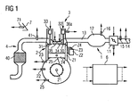
- An internal combustion engine ( FIG. 1 ) comprises an intake tract 1, an engine block 2, a cylinder head 3 and an exhaust tract 4.
- the intake tract 1 preferably comprises a throttle valve 11, furthermore a collector 12 and an intake manifold 13, which lead to a cylinder Z1 via an inlet channel into the engine block 2 is.
- the engine block 2 further comprises a crankshaft 21, which is coupled via a connecting rod 25 with the piston 24 of the cylinder Z1.
- the cylinder head 3 includes a valvetrain with a gas inlet valve 30, a gas outlet valve 31 and valve actuators 32, 33.
- the cylinder head 3 further comprises an injection valve 34 and a spark plug 35.
- the injection valve 34 may also be arranged in the intake manifold 13.
- the exhaust tract 4 comprises a catalyst 40, which is preferably designed as a three-way catalyst.
- a control device 6 is provided, which is associated with sensors which detect different measured variables and in each case determine the measured value of the measured variable.
- the control device 6 determines dependent on at least one of the measured variables manipulated variables, which are then converted into one or more actuating signals for controlling the actuators by means of corresponding actuators.
- the control device 6 can also be referred to as a device for controlling the internal combustion engine.
- the sensors are a pedal position sensor 71, which detects the position of an accelerator pedal 7, an air mass meter 14, which detects an air mass flow upstream of the throttle valve 11, a temperature sensor 15, which detects the intake air temperature, a crankshaft angle sensor 22, which detects a crankshaft angle CRK, then a Speed N is assigned, another temperature sensor 23, which detects a coolant temperature TCO, a camshaft angle sensor 36a, which detects a camshaft angle, a cylinder pressure sensor 37, which detects a pressure p in a combustion chamber of the cylinder Z1, and an exhaust gas probe 41 which a residual oxygen content of the exhaust gas detected and whose measurement signal is characteristic of the air / fuel ratio in the cylinder Z1.
- any subset of said sensors or additional sensors may be present.
- the actuators are, for example, the throttle valve 11, the gas inlet and gas outlet valves 30, 31, the injection valve 34 and the spark plug 35.
- cylinders Z2-Z4 may also be provided, to which corresponding actuators are then assigned.
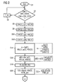
- a program for controlling the internal combustion engine is executed in a step S1 (FIG. FIG. 2 ), in which variables are initialized if necessary.
- a step S2 it is checked whether the current crankshaft angle CRK is greater than a starting crankshaft angle CRK_START. Further, it is checked whether the current crankshaft angle CRK is smaller than a stop crankshaft angle CRK_STOP.
- the starting crankshaft angle CRK_START is preferably selected at about 80 ° crankshaft angle after the ignition top dead center of the piston 24. At the start crankshaft angle CRK_START it is ensured that the combustion of the air / fuel mixture in the combustion chamber of the cylinder Z1 is safely completed.
- crankshaft angle CRK_STOP which is advantageously selected at about 100 ° after the ignition top dead center of the piston 24, it is ensured that the pressure in the cylinder still has a very high value.
- a detection of measured values of the pressure p in the combustion chamber of the cylinder Z1 taking place in the following steps S6 to S12 can be carried out with high quality by means of the cylinder pressure sensor 37.
- Cylinder pressure sensors 37 are usually designed to detect very high pressures. At lower pressures, they may have a larger measurement error.
- step S2 If the condition of step S2 is not fulfilled, the program is continued in a step S4, in which it is for a predetermined waiting time T_W remains before the condition of step S2 is checked again.
- a first measured value p [1] of the pressure in the combustion chamber of the cylinder Z1 is detected by means of the cylinder pressure sensor 37.
- the numbers given in parentheses for the following quantities refer to corresponding values for each crankshaft angle CRK.
- the crankshaft angle CRK [1] is 80 ° after the ignition top dead center
- p [1] is the measured value of the combustion chamber pressure associated with this crankshaft angle CRK [1]
- VOL [1] is the associated volume of the combustion chamber of the cylinder.
- a step S8 at a crankshaft angle CRK [2], which is, for example, 85 ° after the ignition top dead center, a second measured value p [2] of the pressure in the combustion chamber of the cylinder Z1 and the associated volume VOL [2] of the combustion chamber are detected determined.
- a crankshaft angle CRK [3] which is for example 90 ° after the ignition top dead center, a third measured value p [3] of the pressure in the combustion chamber of the cylinder Z1 is detected and the associated volume VOL [3 ] of the combustion chamber of the cylinder Z1 assigned.
- a fourth measured value p [4] of the pressure in the combustion chamber of the cylinder is detected and the corresponding volume VOL [4 ] of the combustion chamber of the cylinder Z1 assigned.
- a polytropic exponent ⁇ then becomes dependent on the first measured value p [1] of the pressure in the combustion chamber of the cylinder Z1, the volume assigned to it VOL [1] of the combustion chamber of the cylinder, the second measured value p [2] of the pressure in the combustion chamber of the cylinder Z1 and the associated volume VOL [2] determined.
- This is preferably done by means of a corresponding resolution of the polytope equation according to the polytropic exponent ⁇ , as shown by way of example in the right-hand part of step S14.
- the polytropic exponent is preferably averaged by multiplying the polytropic exponent K by means of different permutations of the value pairs of steps S6 to S12.
- measurement errors can be reduced and the polytropic exponent ⁇ can thus be determined even more accurately.
- a pressure p [5] in the combustion chamber of the cylinder Z1 is then determined, preferably immediately before the opening of the gas outlet valve 31, depending on the polytropic exponent K, from the second measured value p [2] of the pressure in the combustion chamber the volume VOL [2] associated therewith of the combustion chamber of the cylinder Z1 and the volume VOL [5] assigned to the pressure p [5] in the combustion chamber of the cylinder Z1.
- This is preferably done by means of the formula given on the right side of step S16.
- a suitable cylinder pressure sensor 37 it can also be done by a further detection of a measured value.
- the pressure p [5] in the combustion chamber of the cylinder Z1 can also be determined several times depending on further measured values of the pressure and then averaged.
- a gas constant R is preferably determined as a function of an actual value LAM_AV of the air / fuel ratio in the combustion chamber of the cylinder Z1, which is derived from the measurement signal of the oxygen probe 41.
- the gas constant R is assigned a predetermined value in step S18. Even so, a sufficient accuracy for the individual case in the further calculation can be ensured because the gas constant shows only a small variability.
- a step S20 the temperature T [5] of the exhaust gas in the cylinder Z1 is then dependent on the pressure p [5] in the combustion chamber of the cylinder Z1, the volume VOL [5] associated therewith, the gas constant R and that in the combustion chamber Cylinder Z1 located gas mass M_ZYL determined.
- the gas mass M_ZYL located in the cylinder Z1 can be determined, for example, by means of an intake manifold model depending on an opening degree of the throttle valve and / or the pressure in the collector 12 and / or the air mass flow detected by the air mass sensor 15 taking into account the fuel mass MFF metered in the cylinder Z1 ,
- the calculation of the temperature T [5] is preferably carried out by means of the general gas equation, as indicated on the right side of step S20.
- a pressure p [6] in the combustion chamber of the cylinder which is preferably the pressure at the time at which the gas outlet valve 31 has just closed, is determined by a measurement by means of the cylinder pressure sensor 37.
- a step S36 may be provided in which the pressure p [6] is directly associated with an ambient pressure p_AMB in a particularly simple manner.
- steps S38 and S40 are provided.
- step S38 a pressure p [6 '] associated with a crankshaft angle CRK that is within the crankshaft angle range in which the exhaust gas valve 31 is closed again is determined Gas inlet valve 30 is not opened again, and the time after the pressure p [6] attributable crankshaft angle is. Further, the volume VOL [6 '] to be assigned to the pressure p [6'] is temporarily stored.
- step S40 the pressure p [6] is then determined as a function of the polytropic exponent K, the pressure p [6 '], and the volumes VOL [6], VOL [6']. This is done in accordance with step S16.
- steps S42, S44 and S46 are provided.
- step S42 the pressure p [6 '] and the associated volume VOL [6'] are determined in accordance with the step S38. Furthermore, at least one further pressure p [6 "] is determined, which is assigned to a crankshaft angle CRK which lies within the crankshaft angle range in which the gas outlet valve 31 is closed again, but the gas inlet valve 30 is not yet reopened, and also in time Further, the volume VOL [6 "] to be assigned to the pressure p [6"] is temporarily stored.
- step S44 another polytropic exponent K 'is then determined as a function of the pressures p [6'], p [6 "] and the volumes VOL [6 '], VOL [6"], in accordance with the procedure of step S14. Also in step S44, the further polytropic exponent K 'can be determined as a function of further pressures and associated volumes, specifically as a mean further polytropic exponent.
- the step S46 corresponds to the step S40 with the difference that for determining the pressure p [6] the further or middle further polytropic exponent K 'is used.
- the pressure p [6] can also be determined several times with different further pressures in steps S38 or S46 and then averaged. Thus, measurement errors affect the individual measurements of the pressure less strong.
- a base temperature Tnorm [6] of the exhaust gas to be assigned to the pressure p [6] in the combustion chamber of the cylinder Z1 is determined as a function of the polytropic exponent ⁇ , the pressure p [6] and the pressure p [5] in FIG the combustion chamber of the cylinder Z1 and the temperature T [5] of the exhaust gas in the combustion chamber of the cylinder Z1 determined. This is preferably done by means of the relationship given on the right side of step S24. If step S44 was performed before step S24, the calculation of the base temperature Tnorm [6] may also be made dependent on the polytropic exponent K '.
- a temperature T [6] of the exhaust gas in the cylinder Z1 to be assigned to the pressure p [6] in the combustion chamber of the cylinder Z1 is then determined in a step S26 as a function of the base temperature Tnorm [6], an ambient temperature T_AMB and / or Vehicle speed V of a vehicle in which the internal combustion engine is arranged, and / or the coolant temperature TCO and / or an opening angle CRK_OP and / or a closing angle CRK_CL of the gas outlet valve 31.
- the temperature T [6] can be easily and with high precision. which is in particular the exhaust gas temperature at the time of closing the gas outlet valve 31, determined be without an exhaust back pressure model or a corresponding exhaust back pressure sensor is needed.
- an exhaust gas temperature sensor may also be omitted.
- the influence of the ambient temperature T_AMB, the vehicle speed V or the coolant temperature TCO or the opening angle CRK_OP or the closing angle CRK_CL of the gas outlet valve 31 to the temperature T [6] is preferably taken into account by means of corresponding characteristic curves or characteristic maps.
- an exhaust gas temperature T_KR in the exhaust gas tract and / or a pressure in the exhaust gas tract P_KR can also be taken into account.
- the subsequent steps S28 to S32 are executed when the internal combustion engine is operated by the space ignition method. If, however, the internal combustion engine is operated by means of another combustion method, then the temperature T [6], which is preferably the exhaust-gas temperature at the time of closing the gas outlet valve 31, can be an input variable for any functions of the control device.
- a first fuel mass MFF1 to be supplied is determined as a function of the temperature T [6] of the exhaust gas and a total of the fuel mass MFF to be supplied to the cylinder during a working cycle of the cylinder Z1.
- the first fuel mass MFF1 is metered during an intermediate compression of the cylinder Z1 in the combustion chamber of the cylinder Z1.
- intermediate compression is understood to mean the time duration after the gas outlet valve 31 has been closed and before the gas inlet valve 30 has been opened.
- the first supplied fuel mass MFF1 By metering the first amount of fuel MFF1 during the intermediate compression, an exothermic reaction and fractionation of the metered fuel occurs due to the still low oxygen content in the exhaust gas, resulting in radicals which accelerate the later combustion of the air / fuel mixture in the cylinder ,
- the first supplied fuel mass MFF1 so the timing of the air / fuel mixture can be set effectively. It plays a major role that the temperature T [6] can differ significantly from one working cycle to another and then again has a strong influence on the combustion of the next working cycle. This can be compensated for by appropriately setting the first fuel mass MFF1 and thus a precise adjustment of the ignition timing of the air / fuel mixture.
- a second fuel mass is also determined as a function of the total fuel mass MFF to be metered to the cylinder Z1 and the first fuel mass MFF1. This is preferably done by forming the difference between the total fuel mass MFF to be supplied to the cylinder Z1 and the first fuel mass MFF1.
- the second fuel mass MFF2 is metered into the cylinder Z1 only after the gas inlet valve 30 has been opened.
- a crankshaft angle CRK_MFF1 of the metering of the first fuel mass MFF1 is preferably determined as a function of the temperature T [6] of the exhaust gas.
- the ignition timing of the air / fuel mixture in the cylinder Z1 can also be advantageously influenced by the crankshaft angle CRK_MFF1 of the metering of the first fuel mass MFF1.
- a crankshaft angle CRK_MFF2 is determined as a function of the temperature T [6] of the exhaust gas, which also influences the ignition timing of the air / fuel mixture in the cylinder Z1.
- actuating signals SG for actuating the injection valve 34 are then determined.
- MFF2 be independent of the temperature T [6].
- the first fuel mass MFF1 may be independent of the temperature T [6] of the exhaust gas.
Landscapes
- Engineering & Computer Science (AREA)
- Chemical & Material Sciences (AREA)
- Combustion & Propulsion (AREA)
- Mechanical Engineering (AREA)
- General Engineering & Computer Science (AREA)
- Combined Controls Of Internal Combustion Engines (AREA)
- Electrical Control Of Air Or Fuel Supplied To Internal-Combustion Engine (AREA)
Description
Die Erfindung betrifft ein Verfahren und eine Vorrichtung zum Steuern einer Brennkraftmaschine mit mindestens einem Zylinder, in dem ein Brennraum ausgebildet ist und dem ein Kolben zugeordnet ist mit einem Ansaugtrakt, der abhängig von der Stellung eines Gaseinlassventils mit dem Brennraum des Zylinders kommuniziert, mit einem Abgastrakt, der abhängig von der Stellung eines Gasauslassventils mit dem Brennraum des Zylinders kommuniziert, und mit einem Zylinderdrucksensor, der den Druck in dem Brennraum des Zylinders erfasst.The invention relates to a method and a device for controlling an internal combustion engine having at least one cylinder, in which a combustion chamber is formed and which is associated with a piston with an intake that communicates with the combustion chamber of the cylinder depending on the position of a gas inlet valve, with an exhaust tract which communicates with the combustion chamber of the cylinder depending on the position of a gas outlet valve, and with a cylinder pressure sensor which detects the pressure in the combustion chamber of the cylinder.
Steigende Energiekosten und Verschärfungen gesetzlicher Bestimmungen bezüglich des zulässigen Kraftstoffverbrauchs oder der zulässigen Schadstoffemissionen von Kraftfahrzeugen, in denen Brennkraftmaschinen angeordnet sind, machen es erforderlich, Maßnahmen zu ergreifen, um einerseits den Kraftstoffverbrauch von Brennkraftmaschinen zu senken und andererseits sicherzustellen, dass die von dem Kraftfahrzeug ausgestoßenen Schadstoffemissionen geringe Werte einnehmen. In diesem Zusammenhang ist es bekannt geworden, Brennkraftmaschinen, insbesondere benzinbetriebene, in bestimmten Betriebspunkten mit einem selbstzündenden Brennverfahren zu betreiben, das auch als Homogeneous Charge Compression Ignition (HCCI), Compressed Auto Ignition (CAI) oder Raumzündungsverfahren (RZV) genannt wird. Bei diesem selbstzündenden Brennverfahren wird die Selbstzündung und damit der Verbrennungsverlauf über die reaktive Energiemenge in dem Zylinder der Brennkraftmaschine gesteuert. Diese Energiemenge kann unter anderem durch einen im Vergleich zum konventionell gezündeten Ottomotorenbetrieb sehr hohen Restgasanteil bereitgestellt werden. Auch für konventionell gezündete Ottomotoren ist es bekannt, im unteren und mittleren Teillastbereich die Brennkraftmaschine mit einer hohen Abgasrückführrate zu betreiben, um die Verbrennung bezüglich der Gütekriterien Verbrauch und Emissionen zu optimieren.Rising energy costs and tightening of legal regulations regarding the permissible fuel consumption or the admissible pollutant emissions of motor vehicles, in which internal combustion engines are arranged, make it necessary to take measures to reduce the fuel consumption of internal combustion engines and to ensure that the pollutant emissions emitted by the motor vehicle take low values. In this context, it has become known to operate internal combustion engines, in particular gasoline-operated, at certain operating points with a self-igniting combustion process, which is also known as Homogeneous Charge Compression Ignition (HCCI), Compressed Auto Ignition (CAI) or space ignition method (RZV). In this self-igniting combustion process, the self-ignition and thus the course of combustion is controlled by the amount of reactive energy in the cylinder of the internal combustion engine. This amount of energy can, inter alia, by a compared to the conventionally ignited Petrol engine operation very high residual gas content can be provided. Even for conventionally ignited gasoline engines, it is known to operate in the lower and middle part load range, the internal combustion engine with a high exhaust gas recirculation rate in order to optimize the combustion with respect to the quality criteria consumption and emissions.
Aus der
Aus der
Aus der
Aufgabe der Erfindung ist es, ein Verfahren und eine Vorrichtung zum Steuern einer Brennkraftmaschine zu schaffen, die ein präzises Steuern der Brennkraftmaschine gewährleisten.The object of the invention is to provide a method and an apparatus for controlling an internal combustion engine, which ensure precise control of the internal combustion engine.
Die Erfindung zeichnet sich aus durch ein Verfahren und eine entsprechende Vorrichtung zum Steuern einer Brennkraftmaschine mit mindestens einem Zylinder, in dem ein Brennraum ausgebildet ist und dem ein Kolben zugeordnet ist, mit einem Abgastrakt, der abhängig von der Stellung eines Gasauslassventils mit dem Brennraum des Zylinders kommuniziert, und mit einem Zylinderdrucksensor, der den Druck in dem Brennraum des Zylinders erfasst. Ein Polytropenexponent wird bestimmt abhängig von mindestens zwei Messwerten des Drucks in dem Brennraum, die während des Arbeitstaktes des Zylinders nach Abschluss der Verbrennung eines in dem Zylinder befindlichen Luft/Kraftstoff-Gemisches und vor einem Öffnen des Gasauslassventils erfasst werden. Dem Bestimmen des Polytropenexponent liegt die Erkenntnis zugrunde, dass eine starke Korrelation zwischen Zylinderdruck und Gastemperatur nur nach Abschluss der Verbrennung des Luft/Kraftstoff-Gemisches existiert, während der Temperaturverlauf während der Verbrennung des Luft/Kraftstoff-Gemisches sehr schwer abschätzbar ist.The invention is characterized by a method and a corresponding device for controlling an internal combustion engine having at least one cylinder, in which a combustion chamber is formed and to which a piston is assigned, with an exhaust gas tract, which communicates with the combustion chamber of the cylinder depending on the position of a gas outlet valve, and with a cylinder pressure sensor which detects the pressure in the combustion chamber of the cylinder. A polytropic exponent is determined depending on at least two measurements of the pressure in the combustion chamber detected during the power stroke of the cylinder after completion of combustion of an in-cylinder air-fuel mixture and before opening of the gas exhaust valve. Determining the polytropic exponent is based on the knowledge that a strong correlation between cylinder pressure and gas temperature only exists after completion of the combustion of the air / fuel mixture, while the temperature profile during the combustion of the air / fuel mixture is very difficult to estimate.
Eine erste Temperatur des Abgases wird ermittelt, die charakteristisch ist für die Temperatur des Abgases vor dem Öffnen des Gasauslassventils, insbesondere für die Temperatur des Abgases unmittelbar vor dem Öffnen des Gasauslassventils. Eine zweite Temperatur des Abgases wird ermittelt, das nach dem Schließen des Gasauslassventils in den Brennraum des Zylinders verbleibt, und zwar abhängig von der ersten Temperatur des Abgases, dem der ersten Temperatur zugeordneten Druck in den Brennraum, also dem zu dem Zeitpunkt der ersten Temperatur vorliegenden Druck, ferner abhängig von dem Druck in dem Brennraum nach dem Schließen des Gasauslassventils und dem Polytropenexponenten. Ein Stellsignal zum Steuern eines Stellglieds der Brennkraftmaschine wird erzeugt abhängig von der zweiten Temperatur des Abgases. Die zweite Temperatur kann so einfach und präzise bestimmt werden und wirkt sich auf den Ablauf des nächsten Verbrennungsvorganges des Luft/Kraftstoff-Gemisches in dem Brennraum des Zylinders der Brennkraftmaschine aus. Durch das Erzeugen des Stellsignals zum Steuern eines Stellglieds der Brennkraftmaschine abhängig von der zweiten Temperatur des Abgases kann die Brennkraftmaschine sehr präzise gesteuert werden.A first temperature of the exhaust gas is determined, which is characteristic of the temperature of the exhaust gas before opening the gas outlet valve, in particular for the temperature of the exhaust gas immediately before the opening of the gas outlet valve. A second temperature of the exhaust gas is determined, which remains after closing the gas outlet valve in the combustion chamber of the cylinder, depending on the first temperature of the exhaust gas, the pressure associated with the first temperature in the combustion chamber, that is present at the time of the first temperature Pressure, further depending on the pressure in the combustion chamber after closing the gas outlet valve and the polytropic exponent. An actuating signal for controlling an actuator of the internal combustion engine is generated depending on the second temperature of the exhaust gas. The second temperature can be determined so easily and precisely and has an effect on the sequence of the next combustion process of the air / fuel mixture in the combustion chamber of the cylinder of the internal combustion engine. By generating the actuating signal For controlling an actuator of the internal combustion engine depending on the second temperature of the exhaust gas, the internal combustion engine can be controlled very precisely.
In einer vorteilhaften Ausgestaltung der Erfindung werden die Messwerte des Drucks bei einem Kurbelwellenwinkel größer als einem vorgegebenen Kurbelwellenwinkel erfasst, der so vorgegeben ist, dass die Verbrennung des Luft/Kraftstoff-Gemisches abgeschlossen ist.In an advantageous embodiment of the invention, the measured values of the pressure at a crankshaft angle greater than a predetermined crankshaft angle are detected, which is predetermined so that the combustion of the air / fuel mixture is completed.
In diesem Zusammenhang ist es vorteilhaft, wenn der vorgegebene Kurbelwellenwinkel in etwa 80° nach dem oberen Totpunkt des Kolbens beträgt. Dies hat den Vorteil, dass dann die Verbrennung des Luft/Kraftstoff-Gemisches sicher abgeschlossen ist. Je nach Ausgestaltung der Brennkraftmaschine, insbesondere im Falle eines HCCI-Brennverfahrens kann der vorgegebene Kurbelwellenwinkel auch wesentlich näher an dem oberen Totpunkt des Kolbens gewählt sein.In this context, it is advantageous if the predetermined crankshaft angle is approximately 80 ° after top dead center of the piston. This has the advantage that then the combustion of the air / fuel mixture is completed safely. Depending on the configuration of the internal combustion engine, in particular in the case of an HCCI combustion process, the predetermined crankshaft angle can also be chosen substantially closer to the top dead center of the piston.
In einer weiteren vorteilhaften Ausgestaltung der Erfindung ist der vorgegebene Kurbelwellenwinkel kleiner als in etwa 100° nach dem oberen Totpunkt des Kolbens. Dies hat den Vorteil, dass der Zylinderdruck noch hohe Werte aufweist. Dies trägt insbesondere zur Güte der Steuerung der Brennkraftmaschine stark bei, wenn der Zylinderdrucksensor zum Erfassen hoher Drücke ausgelegt ist und gegebenenfalls beim Erfassen niedriger Drücke einen größeren Messfehler hat. Besonders vorteilhaft ist, wenn die Messwerte des Drucks so erfasst werden, dass zwischen ihnen ein möglichst großer Druckunterschied besteht. Dadurch kann ein Einfluss eines Messfehlers minimiert werden.In a further advantageous embodiment of the invention, the predetermined crankshaft angle is smaller than approximately 100 ° after top dead center of the piston. This has the advantage that the cylinder pressure still has high values. This contributes in particular to the quality of the control of the internal combustion engine greatly when the cylinder pressure sensor is designed to detect high pressures and optionally has a larger measurement error when detecting low pressures. It is particularly advantageous if the measured values of the pressure are detected in such a way that the greatest possible pressure difference exists between them. As a result, an influence of a measurement error can be minimized.
In einer weiteren vorteilhaften Ausgestaltung der Erfindung wird die erste Temperatur des Abgases abhängig von einem Druck in den Brennraum ermittelt, der ermittelt wird abhängig von einem der Messwerte des Drucks in dem Brennraum, der Größe, die charakteristisch ist für das dem jeweiligen Messwert des Drucks zugeordnete Volumen des Brennraums, der Größe, die charakteristisch ist für das Volumen des Brennraums, bei dem das Abgas die erste Temperatur hat, und dem Polytropenexponent. So kann die Lage des Messwertes des Drucks unabhängig von dem Kurbelwellenwinkel gewählt werden, dem die erste Temperatur zugeordnet ist. Dies ist somit insbesondere dann von Vorteil, wenn der Druck präziser bei höheren Druckwerten erfasst werden kann und der Druck relativ niedrig ist, der bei dem Kurbelwellenwinkel in dem Brennraum herrscht, bei dem das Abgas die erste Temperatur hat.In a further advantageous embodiment of the invention, the first temperature of the exhaust gas is determined as a function of a pressure in the combustion chamber, which is determined as a function of one of the measured values of the pressure in the combustion chamber, the variable which is characteristic for the pressure associated with the respective measured value Volume of the combustion chamber, the size that is characteristic of the volume of the combustion chamber, where the exhaust gas has the first temperature, and the polytropic exponent. Thus, the position of the measured value of the pressure can be selected independently of the crankshaft angle to which the first temperature is assigned. This is thus particularly advantageous when the pressure can be detected more precisely at higher pressure values and the pressure is relatively low, which prevails at the crankshaft angle in the combustion chamber, in which the exhaust gas has the first temperature.
In einer weiteren vorteilhaften Ausgestaltung der Erfindung wird die erste Temperatur des Abgases mittels der allgemeinen Gasgleichung ermittelt und die Gaskonstante fest vorgegeben. Dies hat den Vorteil, dass die erste Temperatur so sehr einfach ermittelt werden kann und beruht auf der Erkenntnis, dass der Wert der Gaskonstante nur wenig differiert.In a further advantageous embodiment of the invention, the first temperature of the exhaust gas is determined by means of the general gas equation and the gas constant fixed. This has the advantage that the first temperature can be determined so easily and is based on the finding that the value of the gas constant differs only slightly.
In einer weiteren vorteilhaften Ausgestaltung der Erfindung wird die erste Temperatur des Abgases mittels der allgemeinen Gasgleichung ermittelt und die Gaskonstante abhängig von dem Luft/Kraftstoff-Verhältnis in dem Brennraum des Zylinders ermittelt. Dies hat den Vorteil, dass die erste Temperatur einfach noch präziser ermittelt werden kann und zudem das Luft/Kraftstoff-Verhältnis in dem Brennraum ohnehin im Rahmen einer λ-Regelung ermittelt wird und somit ohne zusätzlichen Aufwand verfügbar ist.In a further advantageous embodiment of the invention, the first temperature of the exhaust gas is determined by means of the general gas equation and the gas constant determined depending on the air / fuel ratio in the combustion chamber of the cylinder. This has the advantage that the first temperature can be determined even more precisely and, in addition, the air / fuel ratio in the combustion chamber is determined anyway in the context of a λ control and is thus available without additional effort.
In einer weiteren vorteilhaften Ausgestaltung der Erfindung wird der Druck in dem Brennraum nach dem Schließen des Gasauslassventils durch einen berechneten Druckwert angenähert und die zweite Temperatur des Abgases abhängig von einem Umgebungsparameter und/oder einer Drehzahl und/oder dem Kurbelwellenwinkel des Öffnens oder Schließens des Gasauslassventils und/oder einer Kühlmitteltemperatur ermittelt. So ist kein physikalisches dynamisches Modell des Verlaufs des Drucks des Abgases, während das Gasauslassventil geöffnet ist, notwendig. Dennoch kann so die zweite Temperatur des Abgases äußerst präzise berücksichtigt werden.In a further advantageous embodiment of the invention, the pressure in the combustion chamber after closing the gas outlet valve is approximated by a calculated pressure value and the second temperature of the exhaust gas depending on an environmental parameter and / or a rotational speed and / or the crankshaft angle of the opening or closing of the gas outlet valve and / or a coolant temperature determined. Thus, no physical dynamic model of the course of the pressure of the exhaust gas while the gas exhaust valve is opened is necessary. Nevertheless, so the second temperature of the exhaust gas can be considered very precisely.
In einer weiteren vorteilhaften Ausgestaltung der Erfindung wird der Druck in dem Brennraum nach dem Schließen des Gasauslassventils ermittelt. Dies erfolgt abhängig von mindestens einem weiteren Druck und den dem mindestens einem weiteren Druck und dem Druck in dem Brennraum nach dem Schließen des Gasauslassventils zuzuordnenden Volumina. Der weitere Druck ist einem Kurbelwellenwinkel zugeordnet, der innerhalb des Kurbelwellenwinkelbereichs liegt, in dem das Gasauslassventil wieder geschlossen ist, aber das Gaseinlassventil noch nicht wieder geöffnet ist, und der weitere Druck wird zeitlich nach dem Druck in dem Brennraum nach dem Schließen des Gasauslassventils erfasst. Der weitere Druck kann so ggf. präziser erfasst werden und damit auch der Druck in dem Brennraum nach dem Schließen des Gasauslassventils präziser ermittelt werden.In a further advantageous embodiment of the invention, the pressure in the combustion chamber is determined after closing the gas outlet valve. This takes place as a function of at least one further pressure and the volumes to be allocated to the at least one additional pressure and the pressure in the combustion chamber after closing the gas outlet valve. The further pressure is associated with a crankshaft angle which is within the crankshaft angle range in which the gas outlet valve is closed again, but the gas inlet valve is not reopened, and the further pressure is detected in time after the pressure in the combustion chamber after closing the gas outlet valve. If necessary, the further pressure can be detected more precisely and thus also the pressure in the combustion chamber can be determined more precisely after closing the gas outlet valve.
In einer weiteren vorteilhaften Ausgestaltung der Erfindung wird ein weiterer Polytropenexponent abhängig von mindestens dem weiteren Druck, noch einem weiteren Druck und den dem mindestens einem weiteren Druck und dem noch einem weiteren Druck in dem Brennraum nach dem Schließen des Gasauslassventils zuzuordnenden Volumina ermittelt. Der noch weitere Druck ist einem Kurbelwellenwinkel zugeordnet, der innerhalb des Kurbelwellenwinkelbereichs liegt, in dem das Gasauslassventil wieder geschlossen ist, aber das Gaseinlassventil noch nicht wieder geöffnet ist, und der noch weitere Druck wird zeitlich nach dem Druck in dem Brennraum nach dem Schließen des Gasauslassventils erfasst. Der weitere Polytropenexponent ist dann noch genauer für das Ermitteln des Drucks in dem Brennraum nach dem Schließen des Gasauslassventils.In a further advantageous embodiment of the invention, another polytropic exponent is dependent on at least the further pressure, still another pressure and the at least one further pressure and the still another pressure in the combustion chamber after closing the gas outlet valve determined volumes determined. The still further pressure is associated with a crankshaft angle which is within the crankshaft angle range in which the gas outlet valve is closed again, but the gas inlet valve is not yet reopened, and the still further pressure is timed after the pressure in the combustion chamber after closing the gas outlet valve detected. The further polytropic exponent is then more accurate for determining the pressure in the combustion chamber after closing the gas outlet valve.
In einer weiteren vorteilhaften Ausgestaltung der Erfindung wird eine erste Kraftstoffmasse abhängig von der zweiten Temperatur ermittelt, die nach dem Schließen des Gasauslassventils und vor dem Öffnen des Gaseinlassventils in dem Brennraum des Zylinders zugemessen werden soll, und das Einspritzventil wird entsprechend angesteuert. Dies ist insbesondere bei einem selbstzündenden Brennverfahren von Vorteil, bei dem bevorzugt eine hohe Abgasrückführrate eingestellt wird, um die hohen Zündtemperaturen zu erreichen. Durch das Ermitteln der ersten Kraftstoffmasse abhängig von der zweiten Temperatur kann so der Verbrennungsschwerpunkt präzise eingestellt werden. Die Lage des Verbrennungsschwerpunktes hängt ohne Berücksichtigung der zweiten Temperatur sehr stark ab von der Qualität der vorangehenden Verbrennung, die sich auf die zweite Temperatur stark auswirkt.In a further advantageous embodiment of the invention, a first fuel mass is determined as a function of the second temperature, which is to be measured after closing the gas outlet and before opening the gas inlet valve in the combustion chamber of the cylinder, and the injection valve is driven accordingly. This is particularly advantageous in the case of a self-igniting combustion method in which a high exhaust gas recirculation rate is preferably set in order to achieve the high ignition temperatures. By determining the first fuel mass as a function of the second temperature, the focal point of combustion can thus be set precisely. The location of the focus of combustion, without regard to the second temperature, depends very much on the quality of the preceding combustion, which has a strong effect on the second temperature.
In diesem Zusammenhang ist es auch vorteilhaft, wenn ein Kurbelwellenwinkel, an dem die erste Kraftstoffmasse zugemessen wird, abhängig von der zweiten Temperatur ermittelt wird. Auf diese Weise kann der Verbrennungsschwerpunkt bei einem selbstzündenden Brennverfahren präzise eingestellt werden.In this context, it is also advantageous if a crankshaft angle, at which the first fuel mass is metered, is determined as a function of the second temperature. In this way, the combustion focus can be precisely adjusted in a self-igniting combustion process.
In einer weiteren vorteilhaften Ausgestaltung der Erfindung wird der Kurbelwellenwinkel, an dem eine zweite Kraftstoffmasse zugemessen wird, abhängig von der zweiten Temperatur ermittelt, wobei die zweite Kraftstoffmasse nach dem Öffnen des Gaseinlassventils in den Zylinder zugemessen wird. Auch auf diese Weise kann ein Verbrennungsschwerpunkt bei einem selbstzündenden Brennverfahren präzise eingestellt werden.In a further advantageous embodiment of the invention, the crankshaft angle at which a second fuel mass is metered, determined depending on the second temperature, wherein the second fuel mass is metered into the cylinder after opening the gas inlet valve. Also in this way, a combustion focus can be precisely adjusted in a self-igniting combustion process.
Ausführungsbeispiele der Erfindung sind im Folgenden anhand der schematischen Zeichnungen erläutert. Es zeigen:
Figur 1- eine Brennkraftmaschine mit einer Steuereinrichtung,
Figur 2- ein Ablaufdiagramm eines ersten Teils eines Programms zum Steuern der Brennkraftmaschine und
Figur 3- ein Ablaufdiagramm eines zweiten Teils des Programms zum Steuern der Brennkraftmaschine.
- FIG. 1
- an internal combustion engine with a control device,
- FIG. 2
- a flowchart of a first part of a program for controlling the internal combustion engine and
- FIG. 3
- a flowchart of a second part of the program for controlling the internal combustion engine.
Elemente gleicher Konstruktion oder Funktion sind figurenübergreifend mit den gleichen Bezugszeichen gekennzeichnet.Elements of the same construction or function are identified across the figures with the same reference numerals.
Eine Brennkraftmaschine (
Der Zylinderkopf 3 umfasst einen Ventiltrieb mit einem Gaseinlassventil 30, einem Gasauslassventil 31 und Ventilantrieben 32, 33. Der Zylinderkopf 3 umfasst ferner ein Einspritzventil 34 und eine Zündkerze 35. Alternativ kann das Einspritzventil 34 auch in dem Saugrohr 13 angeordnet sein.The
Der Abgastrakt 4 umfasst einen Katalysator 40, der bevorzugt als Dreiwegekatalysator ausgebildet ist.The
Ferner ist eine Steuereinrichtung 6 vorgesehen, der Sensoren zugeordnet sind, die verschiedene Messgrößen erfassen und jeweils den Messwert der Messgröße ermitteln. Die Steuereinrichtung 6 ermittelt abhängig von mindestens einer der Messgrößen Stellgrößen, die dann in ein oder mehrere Stellsignale zum Steuern der Stellglieder mittels entsprechender Stellantriebe umgesetzt werden. Die Steuereinrichtung 6 kann auch als Vorrichtung zum Steuern der Brennkraftmaschine bezeichnet werden.Furthermore, a
Die Sensoren sind ein Pedalstellungsgeber 71, welcher die Stellung eines Fahrpedals 7 erfasst, ein Luftmassenmesser 14, welcher einen Luftmassenstrom stromaufwärts der Drosselklappe 11 erfasst, ein Temperatursensor 15, welcher die Ansauglufttemperatur erfasst, ein Kurbelwellenwinkelsensor 22, welcher einen Kurbelwellenwinkel CRK erfasst, dem dann eine Drehzahl N zugeordnet wird, ein weiterer Temperatursensor 23, der eine Kühlmitteltemperatur TCO erfasst, ein Nockenwellenwinkelsensor 36a, der einen Nockenwellenwinkel erfasst, ein Zylinderdrucksensor 37, der einen Druck p in einem Brennraum des Zylinders Z1 erfasst, und eine Abgassonde 41 welche einen Restsauerstoffgehalt des Abgases erfasst und deren Messsignal charakteristisch ist für das Luft/Kraftstoff-Verhältnis in dem Zylinder Z1. Je nach Ausführungsform der Erfindung kann eine beliebige Untermenge der genannten Sensoren oder auch zusätzliche Sensoren vorhanden sein.The sensors are a
Die Stellglieder sind beispielsweise die Drosselklappe 11, die Gaseinlass- und Gasauslassventile 30, 31, das Einspritzventil 34 und die Zündkerze 35.The actuators are, for example, the
Neben dem Zylinder Z1 können auch noch weitere Zylinder Z2-Z4 vorgesehen sein, denen dann auch entsprechende Stellglieder zugeordnet sind.In addition to the cylinder Z1, other cylinders Z2-Z4 may also be provided, to which corresponding actuators are then assigned.
Ein Programm zum Steuern der Brennkraftmaschine wird in einem Schritt S1 (
In einem Schritt S2 wird geprüft, ob der aktuelle Kurbelwellenwinkel CRK größer ist als ein Start-Kurbelwellenwinkel CRK_START. Ferner wird geprüft, ob der aktuelle Kurbelwellenwinkel CRK kleiner ist als ein Stopp-Kurbelwellenwinkel CRK_STOP. Der Start-Kurbelwellenwinkel CRK_START ist vorzugsweise bei in etwa 80° Kurbelwellenwinkel nach dem Zünd-oberen Totpunkt des Kolbens 24 gewählt. Bei dem Start-Kurbelwellenwinkel CRK_START ist sichergestellt, dass die Verbrennung des in den Brennraum des Zylinders Z1 befindlichen Luft/Kraftstoff-Gemisches sicher abgeschlossen ist.In a step S2 it is checked whether the current crankshaft angle CRK is greater than a starting crankshaft angle CRK_START. Further, it is checked whether the current crankshaft angle CRK is smaller than a stop crankshaft angle CRK_STOP. The starting crankshaft angle CRK_START is preferably selected at about 80 ° crankshaft angle after the ignition top dead center of the
Bei einem Kurbelwellenwinkel CRK_STOP, der vorteilhaft bei in etwa 100° nach dem Zünd-oberen Totpunkt des Kolbens 24 gewählt ist, ist sichergestellt, dass der Druck in dem Zylinder noch einen sehr hohen Wert aufweist. Ein in den nachfolgenden Schritten S6 bis S12 erfolgende Erfassung von Messwerten des Drucks p in dem Brennraum des Zylinders Z1 kann dabei mit hoher Güte mittels des Zylinderdrucksensors 37 erfolgen. Zylinderdrucksensoren 37 sind in der Regel zum Erfassen sehr hoher Drücke ausgelegt. Bei niedrigeren Drücken haben sie gegebenenfalls einen größeren Messfehler.At a crankshaft angle CRK_STOP, which is advantageously selected at about 100 ° after the ignition top dead center of the
Ist die Bedingung des Schrittes S2 nicht erfüllt, so wird das Programm in einem Schritt S4 fortgesetzt, in dem es für eine vorgegebene Wartezeit T_W verharrt, bevor die Bedingung des Schrittes S2 erneut geprüft wird.If the condition of step S2 is not fulfilled, the program is continued in a step S4, in which it is for a predetermined waiting time T_W remains before the condition of step S2 is checked again.
Ist die Bedingung des Schrittes S2 hingegen erfüllt, so wird in einem Schritt S6 ein erster Messwert p[1] des Drucks in den Brennraum des Zylinders Z1 mittels des Zylinderdrucksensors 37 erfasst. Die bei den nachfolgenden Größen in Klammern angegebene Zahlen beziehen sich jeweils auf zugehörige Werte bei jeweils einem Kurbelwellenwinkel CRK. So beträgt der Kurbelwellenwinkel CRK[1] beispielsweise 80° nach dem Zünd-oberen Totpunkt, p[1] ist der diesem Kurbelwellenwinkel CRK[1] zugeordnete Messwert des Brennraumdrucks und VOL[1] ist das zugehörige Volumen des Brennraums des Zylinders.If, on the other hand, the condition of step S2 is satisfied, in a step S6 a first measured value p [1] of the pressure in the combustion chamber of the cylinder Z1 is detected by means of the cylinder pressure sensor 37. The numbers given in parentheses for the following quantities refer to corresponding values for each crankshaft angle CRK. For example, the crankshaft angle CRK [1] is 80 ° after the ignition top dead center, p [1] is the measured value of the combustion chamber pressure associated with this crankshaft angle CRK [1], and VOL [1] is the associated volume of the combustion chamber of the cylinder.
In einem Schritt S8 werden bei einem Kurbelwellenwinkel CRK[2], der beispielsweise 85° nach dem Zünd-oberen Totpunkt beträgt ein zweiter Messwert p[2] des Drucks in den Brennraum des Zylinders Z1 erfasst und das zugehörige Volumen VOL[2] des Brennraums ermittelt. In einem gegebenenfalls vorgesehenen Schritt S10 wird bei einem Kurbelwellenwinkel CRK[3], der beispielsweise 90° nach dem Zünd-oberen Totpunkt beträgt, ein dritter Messwert p[3] des Drucks in dem Brennraum des Zylinders Z1 erfasst und das zugehörige Volumen VOL [3] des Brennraums des Zylinders Z1 zugeordnet. Ebenso wird in einem gegebenenfalls vorhandenen Schritt S12 bei einem Kurbelwellenwinkel CRK[4], der beispielsweise 100° nach dem Zünd-oberen Totpunkt beträgt, ein vierter Messwert p[4] des Drucks in den Brennraum des Zylinders erfasst und das entsprechende Volumen VOL[4] des Brennraums des Zylinders Z1 zugeordnet.In a step S8, at a crankshaft angle CRK [2], which is, for example, 85 ° after the ignition top dead center, a second measured value p [2] of the pressure in the combustion chamber of the cylinder Z1 and the associated volume VOL [2] of the combustion chamber are detected determined. In an optionally provided step S10, at a crankshaft angle CRK [3], which is for example 90 ° after the ignition top dead center, a third measured value p [3] of the pressure in the combustion chamber of the cylinder Z1 is detected and the associated volume VOL [3 ] of the combustion chamber of the cylinder Z1 assigned. Likewise, in a possibly existing step S12 at a crankshaft angle CRK [4], which is for example 100 ° after the ignition top dead center, a fourth measured value p [4] of the pressure in the combustion chamber of the cylinder is detected and the corresponding volume VOL [4 ] of the combustion chamber of the cylinder Z1 assigned.
In einem Schritt S14 wird anschließend ein Polytropenexponent κ abhängig von dem ersten Messwert p[1] des Drucks in dem Brennraum des Zylinders Z1, des diesem zugeordnete Volumen VOL[1] des Brennraums des Zylinders, des zweiten Messwertes p[2] des Drucks in dem Brennraum des Zylinders Z1 und des zugeordneten Volumens VOL[2] ermittelt. Dies erfolgt vorzugsweise mittels entsprechender Auflösung der Polytropengleichung nach dem Polytropenexponenten κ, wie es beispielhaft in dem rechten Teil des Schrittes S14 wiedergegeben ist.In a step S14, a polytropic exponent κ then becomes dependent on the first measured value p [1] of the pressure in the combustion chamber of the cylinder Z1, the volume assigned to it VOL [1] of the combustion chamber of the cylinder, the second measured value p [2] of the pressure in the combustion chamber of the cylinder Z1 and the associated volume VOL [2] determined. This is preferably done by means of a corresponding resolution of the polytope equation according to the polytropic exponent κ, as shown by way of example in the right-hand part of step S14.
Bevorzugt wird der Polytropenexponent gemittelt durch mehrfaches Ermitteln des Polytropenexponenten K mittels verschiedener Permutationen der Wertepaare der Schritte S6 bis S12. So können Messfehler verringert werden und der Polytropenexponent κ somit noch genauer ermittelt werden.The polytropic exponent is preferably averaged by multiplying the polytropic exponent K by means of different permutations of the value pairs of steps S6 to S12. Thus, measurement errors can be reduced and the polytropic exponent κ can thus be determined even more accurately.
In einem Schritt S16 wird dann ein Druck p[5] in dem Brennraum des Zylinders Z1 ermittelt, vorzugsweise unmittelbar vor dem Öffnen des Gasauslassventils 31, abhängig von dem Polytropenexponenten K, von dem zweiten Messwert p[2] des Drucks in dem Brennraum, von dem diesem zugeordneten Volumen VOL[2] des Brennraums des Zylinders Z1 und von dem dem Druck p[5] in dem Brennraum des Zylinders Z1 zugeordnete Volumen VOL[5]. Dies erfolgt vorzugsweise mittels der auf der rechten Seite des Schrittes S16 angegebenen Formel. Es kann jedoch alternativ, bei einem geeigneten Zylinderdrucksensor 37 auch durch ein weiteres Erfassen eines Messwertes erfolgen. Bevorzugt kann der Druck p[5] in dem Brennraum des Zylinders Z1 auch mehrfach abhängig von weiteren Messwerten des Drucks ermittelt werden und dann gemittelt werden.In a step S16, a pressure p [5] in the combustion chamber of the cylinder Z1 is then determined, preferably immediately before the opening of the
In einem Schritt S18 wird eine Gaskonstante R bevorzugt abhängig von einem Istwert LAM_AV des Luft/Kraftstoff-Verhältnisses in dem Brennraum des Zylinders Z1 ermittelt, das von dem Messsignal der Sauerstoffsonde 41 abgeleitet ist. In einer einfacheren Ausgestaltung des Programms wird der Gaskonstante R in dem Schritt S18 ein vorgegebener Wert zugeordnet. Auch so kann eine für den Einzelfall ausreichende Genauigkeit bei der weiteren Berechnung sichergestellt werden, da die Gaskonstante nur eine geringe Variabilität zeigt.In a step S18, a gas constant R is preferably determined as a function of an actual value LAM_AV of the air / fuel ratio in the combustion chamber of the cylinder Z1, which is derived from the measurement signal of the
In einem Schritt S20 wird dann die Temperatur T[5] des in dem Zylinder Z1 befindlichen Abgases abhängig von dem Druck p[5] in dem Brennraum des Zylinders Z1, des diesem zugeordneten Volumens VOL[5], der Gaskonstante R und der in dem Zylinder Z1 befindlichen Gasmasse M_ZYL ermittelt. Die in dem Zylinder Z1 befindliche Gasmasse M_ZYL kann beispielsweise mittels eines Saugrohrmodells abhängig von einem Öffnungsgrad der Drosselklappe und/oder dem Druck in dem Sammler 12 und/oder dem von den Luftmassensensor 15 erfassten Luftmassenstrom ermittelt werden unter Berücksichtigung der in dem Zylinder Z1 zugemessenen Kraftstoffmasse MFF. Das Berechnen der Temperatur T[5] erfolgt vorzugsweise mittels der allgemeinen Gasgleichung, wie sie auf der rechten Seite des Schrittes S20 angegeben ist.In a step S20, the temperature T [5] of the exhaust gas in the cylinder Z1 is then dependent on the pressure p [5] in the combustion chamber of the cylinder Z1, the volume VOL [5] associated therewith, the gas constant R and that in the combustion chamber Cylinder Z1 located gas mass M_ZYL determined. The gas mass M_ZYL located in the cylinder Z1 can be determined, for example, by means of an intake manifold model depending on an opening degree of the throttle valve and / or the pressure in the
In einem Schritt S22 wird ein Druck p[6] in dem Brennraum des Zylinders, der bevorzugt der Druck ist, zu dem Zeitpunkt, an dem das Gasauslassventil 31 gerade wieder geschlossen hat, durch eine Messung mittels des Zylinderdrucksensors 37 ermittelt. Alternativ zu dem Schritt S22 kann ein Schritt S36 vorgesehen sein, in dem dem Druck p[6] in besonders einfacher Weise direkt ein Umgebungsdruck p_AMB zugeordnet wird.In a step S22, a pressure p [6] in the combustion chamber of the cylinder, which is preferably the pressure at the time at which the
In einer weiteren Alternative zu dem Schritt S22 sind Schritte S38 und S40 vorgesehen. In dem Schritt S38 wird ein Druck p[6'] ermittelt, der einem Kurbelwellenwinkel CRK zugeordnet ist, der innerhalb des Kurbelwellenwinkelbereichs liegt, in dem das Gasauslassventil 31 wieder geschlossen ist, aber das Gaseinlassventil 30 noch nicht wieder geöffnet ist, und der zeitlich nach dem dem Druck p[6] zuzuordnenden Kurbelwellenwinkel liegt. Ferner wird das dem Druck p[6'] zuzuordnende Volumen VOL[6'] zwischengespeichert.In a further alternative to step S22, steps S38 and S40 are provided. In step S38, a pressure p [6 '] associated with a crankshaft angle CRK that is within the crankshaft angle range in which the
In dem anschließenden Schritt S40 wird dann der Druck p[6] ermittelt abhängig von dem Polytropenexponenten K, dem Druck p[6'], und den Volumina VOL[6], VOL[6']. Dies erfolgt entsprechend dem Schritt S16.In the subsequent step S40, the pressure p [6] is then determined as a function of the polytropic exponent K, the pressure p [6 '], and the volumes VOL [6], VOL [6']. This is done in accordance with step S16.
In einer weiteren Alternative zu dem Schritt S22 sind Schritte S42, S44 und S46 vorgesehen. In dem Schritt S42 wird entsprechend dem Schritt S38 der Druck p[6'] und das zugehörige Volumen VOL[6'] ermittelt. Ferner wird mindestens noch ein weiterer Druck p[6"]ermittelt, der einem Kurbelwellenwinkel CRK zugeordnet ist, der innerhalb des Kurbelwellenwinkelbereichs liegt, in dem das Gasauslassventil 31 wieder geschlossen ist, aber das Gaseinlassventil 30 noch nicht wieder geöffnet ist, und der zeitlich ebenfalls nach dem dem Druck p[6] zuzuordnenden Kurbelwellenwinkel liegt. Ferner wird das dem Druck p[6"] zuzuordnende Volumen VOL[6"] zwischengespeichert.In a further alternative to step S22, steps S42, S44 and S46 are provided. In step S42, the pressure p [6 '] and the associated volume VOL [6'] are determined in accordance with the step S38. Furthermore, at least one further pressure p [6 "] is determined, which is assigned to a crankshaft angle CRK which lies within the crankshaft angle range in which the
In dem Schritt S44 wird dann ein weiterer Polytropenexponent K' abhängig von den Drücken p[6'], p[6"] und den Volumina VOL[6'], VOL[6"] ermittelt und zwar entsprechend der Vorgehensweise des Schrittes S14. Auch in dem Schritt S44 kann der weitere Polytropenexponent K' abhängig von weiteren Drücken und zugeordneten Volumina ermittelt werden und zwar als mittlerer weiterer Polytropenexponent.In step S44, another polytropic exponent K 'is then determined as a function of the pressures p [6'], p [6 "] and the volumes VOL [6 '], VOL [6"], in accordance with the procedure of step S14. Also in step S44, the further polytropic exponent K 'can be determined as a function of further pressures and associated volumes, specifically as a mean further polytropic exponent.
Der Schritt S46 entspricht dem Schritt S40 mit dem Unterschied, dass zum Ermitteln des Drucks p[6] der weitere oder mittlere weitere Polytropenexponent K' eingesetzt wird.The step S46 corresponds to the step S40 with the difference that for determining the pressure p [6] the further or middle further polytropic exponent K 'is used.
Der Druck p[6] kann zusätzlich in den Schritten S38 oder S46 auch mehrfach mit unterschiedlichen weiteren Drücken ermittelt werden und dann gemittelt werden. So wirken sich Messfehler bei den einzelnen Messungen des Drucks weniger stark aus.In addition, the pressure p [6] can also be determined several times with different further pressures in steps S38 or S46 and then averaged. Thus, measurement errors affect the individual measurements of the pressure less strong.
In einem Schritt S24 wird dann anschließend eine dem Druck p[6] in dem Brennraum des Zylinders Z1 zuzuordnende Basis-Temperatur Tnorm[6] des Abgases abhängig von dem Polytropenexponenten κ, dem Druck p[6] und dem Druck p[5] in dem Brennraum des Zylinders Z1 und der Temperatur T[5] des Abgases in dem Brennraum des Zylinders Z1 ermittelt. Dies erfolgt bevorzugt mittels der auf der rechten Seite des Schrittes S24 angegebenen Beziehung. Falls vor dem Schritt S24 der Schritt S44 durchgeführt wurde, kann das Berechnen der Basis-Temperatur Tnorm[6] auch abhängig von dem Polytropenexponenten K' erfolgen.Then, in a step S24, a base temperature Tnorm [6] of the exhaust gas to be assigned to the pressure p [6] in the combustion chamber of the cylinder Z1 is determined as a function of the polytropic exponent κ, the pressure p [6] and the pressure p [5] in FIG the combustion chamber of the cylinder Z1 and the temperature T [5] of the exhaust gas in the combustion chamber of the cylinder Z1 determined. This is preferably done by means of the relationship given on the right side of step S24. If step S44 was performed before step S24, the calculation of the base temperature Tnorm [6] may also be made dependent on the polytropic exponent K '.
Eine dem Druck p[6] in dem Brennraum des Zylinders Z1 zuzuordnende Temperatur T[6] des Abgases in dem Zylinder Z1 wird anschließend in einem Schritt S26 ermittelt abhängig von der Basis-Temperatur Tnorm[6], einer Umgebungstemperatur T_AMB und/oder einer Fahrzeuggeschwindigkeit V eines Fahrzeugs, in dem die Brennkraftmaschine angeordnet ist, und/oder der Kühlmitteltemperatur TCO und/ oder einem Öffnungswinkel CRK_OP und/oder einem Schließwinkel CRK_CL des Gasauslassventils 31. Auf diese Weise kann einfach und mit hoher Präzision die Temperatur T[6], die insbesondere die Abgastemperatur zum Zeitpunkt des Schließens des Gasauslassventils 31 ist, ermittelt werden, ohne dass ein Abgasgegendruckmodell oder ein entsprechender Abgasgegendrucksensor benötigt wird. Ferner kann ebenfalls ein Abgastemperatursensor entfallen. Der Einfluss der Umgebungstemperatur T_AMB, der Fahrzeuggeschwindigkeit V oder der Kühlmitteltemperatur TCO oder des Öffnungswinkels CRK_OP oder des Schließwinkels CRK_CL des Gasauslassventils 31 auf die Temperatur T[6] wird vorzugsweise mittels entsprechender Kennlinien oder Kennfelder berücksichtigt. Alternativ oder zusätzlich kann beim Ermitteln der Temperatur T[6] auch noch eine Abgastemperatur T_KR in dem Abgastrakt und/oder ein Druck in dem Abgastrakt P_KR berücksichtigt werden.A temperature T [6] of the exhaust gas in the cylinder Z1 to be assigned to the pressure p [6] in the combustion chamber of the cylinder Z1 is then determined in a step S26 as a function of the base temperature Tnorm [6], an ambient temperature T_AMB and / or Vehicle speed V of a vehicle in which the internal combustion engine is arranged, and / or the coolant temperature TCO and / or an opening angle CRK_OP and / or a closing angle CRK_CL of the
Die nachfolgenden Schritte S28 bis S32 werden abgearbeitet, wenn die Brennkraftmaschine mittels des Raumzündungsverfahrens betrieben wird. Wird die Brennkraftmaschine hingegen mittels eines anderen Brennverfahrens betrieben, so kann die Temperatur T[6], die bevorzugt die Abgastemperatur im Zeitpunkt des Schließens des Gasauslassventils 31 ist, eine Eingangsgröße für beliebige Funktionen der Steuereinrichtung sein.The subsequent steps S28 to S32 are executed when the internal combustion engine is operated by the space ignition method. If, however, the internal combustion engine is operated by means of another combustion method, then the temperature T [6], which is preferably the exhaust-gas temperature at the time of closing the
In einem Schritt S28 wird eine zuzuführende erste Kraftstoffmasse MFF1 abhängig von der Temperatur T[6] des Abgases und einer gesamt dem Zylinder während eines Arbeitsspiels des Zylinders Z1 zuzuführenden Kraftstoffmasse MFF ermittelt. Die erste Kraftstoffmasse MFF1 wird während einer Zwischenkompression des Zylinders Z1 in dem Brennraum des Zylinders Z1 zugemessen. Unter Zwischenkompression wird in diesem Zusammenhang verstanden die Zeitdauer nach dem Schließen des Gasauslassventils 31 und vor dem Öffnen des Gaseinlassventils 30.In a step S28, a first fuel mass MFF1 to be supplied is determined as a function of the temperature T [6] of the exhaust gas and a total of the fuel mass MFF to be supplied to the cylinder during a working cycle of the cylinder Z1. The first fuel mass MFF1 is metered during an intermediate compression of the cylinder Z1 in the combustion chamber of the cylinder Z1. In this context, intermediate compression is understood to mean the time duration after the
Durch das Zumessen der ersten Kraftstoffmenge MFF1 während der Zwischenkompression erfolgt aufgrund des in der Regel noch geringen Sauerstoffanteils in dem Abgas eine exotherme Reaktion und ein Fraktionieren des zugemessenen Kraftstoffs, wobei Radikale entstehen, die die spätere Verbrennung des Luft/Kraftstoff-Gemisches in dem Zylinder beschleunigen. Durch die erste zuzuführende Kraftstoffmasse MFF1 kann so der Zeitpunkt des Luft/Kraftstoff-Gemisches wirksam eingestellt werden. Dabei spielt eine große Rolle, dass die Temperatur T[6] von Arbeitsspiel zu Arbeitsspiel sich deutlich unterscheiden kann und dann wiederum einen starken Einfluss auf die Verbrennung des nächsten Arbeitsspiels nimmt. Dies kann durch entsprechendes Einstellen der ersten Kraftstoffmasse MFF1 ausgeglichen werden und so eine präzise Einstellung des Zündzeitpunktes des Luft/Kraftstoff-Gemisches erfolgen. Ferner wird in dem Schritt S28 auch noch eine zweite Kraftstoffmasse abhängig von der gesamt dem Zylinder Z1 zuzumessenden Kraftstoffmasse MFF und der ersten Kraftstoffmasse MFF1 ermittelt. Dies erfolgt bevorzugt durch Bilden der Differenz der gesamt dem Zylinder Z1 zuzuführenden Kraftstoffmasse MFF und der ersten Kraftstoffmasse MFF1. Die zweite Kraftstoffmasse MFF2 wird erst nach dem Öffnen des Gaseinlassventils 30 in den Zylinder Z1 zugemessen.By metering the first amount of fuel MFF1 during the intermediate compression, an exothermic reaction and fractionation of the metered fuel occurs due to the still low oxygen content in the exhaust gas, resulting in radicals which accelerate the later combustion of the air / fuel mixture in the cylinder , By the first supplied fuel mass MFF1 so the timing of the air / fuel mixture can be set effectively. It plays a major role that the temperature T [6] can differ significantly from one working cycle to another and then again has a strong influence on the combustion of the next working cycle. This can be compensated for by appropriately setting the first fuel mass MFF1 and thus a precise adjustment of the ignition timing of the air / fuel mixture. Furthermore, in step S28, a second fuel mass is also determined as a function of the total fuel mass MFF to be metered to the cylinder Z1 and the first fuel mass MFF1. This is preferably done by forming the difference between the total fuel mass MFF to be supplied to the cylinder Z1 and the first fuel mass MFF1. The second fuel mass MFF2 is metered into the cylinder Z1 only after the
In einem Schritt S30 wird ein Kurbelwellenwinkel CRK_MFF1 des Zumessens der ersten Kraftstoffmasse MFF1 bevorzugt abhängig von der Temperatur T[6] des Abgases ermittelt. Auch durch den Kurbelwellenwinkel CRK_MFF1 des Zumessens der ersten Kraftstoffmasse MFF1 kann vorteilhaft der Zündzeitpunkt des Luft/Kraftstoff-Gemisches in dem Zylinder Z1 beeinflusst werden.In a step S30, a crankshaft angle CRK_MFF1 of the metering of the first fuel mass MFF1 is preferably determined as a function of the temperature T [6] of the exhaust gas. The ignition timing of the air / fuel mixture in the cylinder Z1 can also be advantageously influenced by the crankshaft angle CRK_MFF1 of the metering of the first fuel mass MFF1.
In einem Schritt S32 wird ein Kurbelwellenwinkel CRK_MFF2 abhängig von der Temperatur T[6] des Abgases ermittelt, der auch den Zündzeitpunkt des Luft/Kraftstoff-Gemisches in dem Zylinder Z1 beeinflusst.In a step S32, a crankshaft angle CRK_MFF2 is determined as a function of the temperature T [6] of the exhaust gas, which also influences the ignition timing of the air / fuel mixture in the cylinder Z1.
In einem Schritt S34 werden dann entsprechende Stellsignale SG zum Ansteuern des Einspritzventils 34 ermittelt. Alternativ kann z.B. auch in den Schritten S30 und S32 der Kurbelwellenwinkel CRK_MFF1 und/oder der Kurbelwellenwinkel CRK_MFF2 des Zumessens der ersten bzw. zweiten Kraftstoffmasse MFF1, MFF2 unabhängig von der Temperatur T[6] sein. Ferner kann alternativ auch die erste Kraftstoffmasse MFF1 unabhängig von der Temperatur T[6] des Abgases sein. Zum Ansteuern der Einspritzventile 34 weiterer Zylinder Z2 bis Z4 werden dann in der Steuereinrichtung 6 entsprechende Programme abgearbeitet. In a step S34, corresponding actuating signals SG for actuating the
Claims (14)
- Method for controlling an internal combustion engine having at least one cylinder (Z1 to Z4) in which is embodied a combustion chamber and to which is assigned a piston (24), having an exhaust manifold (4) that communicates with the combustion chamber of the cylinder (Z1 to Z4) as a function of the position of a gas exhaust valve (31), and having a cylinder pressure sensor (37) that registers the pressure (p) in the combustion chamber of the cylinder (Z1 to Z4),
wherein- a polytropic exponent (K) is determined as a function of at least two measured values (p[1], p[2], p[3], p[4]) of the pressure (p) in the combustion chamber that are registered during the power stroke of the cylinder (Z1 to Z4) once an air/fuel mixture contained in the cylinder (Z1 to Z4) has been completely burned and before the gas exhaust valve (31) opens,- a first temperature (T[5]) of the exhaust gas is determined that is characteristic of the temperature of the exhaust gas before the gas exhaust valve (31) opens,- a second temperature (T[6]) of the exhaust gas remaining in the combustion chamber of the cylinder after the gas exhaust valve (31) closes is determined, specifically as a function of the first temperature (T[5]) of the exhaust gas, of the pressure (p[5]), assigned to said temperature, in the combustion chamber, of the pressure (p[6]) in the combustion chamber after the gas exhaust valve has closed (31), and of the polytropic exponent (K) , and- an actuation signal (SG) for controlling an actuating member of the internal combustion engine is generated as a function of the second temperature (T[6]) of the exhaust gas. - Method according to claim 1,
wherein the measured values (p[1], p[2], p[3], p[4]) of the pressure (p) of the exhaust gas in the combustion chamber of the cylinder (Z1 to Z4) are registered at a crankshaft angle (CRK) greater than a predefined crankshaft angle that is predefined such that burning of the air/fuel mixture will have been completed. - Method according to claim 2,
wherein the predefined crankshaft angle is greater than or equal to around 80° after the top dead centre of the piston (24). - Method according to claim 2 or 3,
wherein the predefined crankshaft angle is less than or equal to around 100° after the top dead centre of the piston (24). - Method according to one of the preceding claims,
wherein the first temperature (T[5]) of the exhaust gas is determined as a function of a pressure (p[5]) in the combustion chamber, which pressure is determined as a function of one of the measured values (p[1], p[2], p[3], p[4]) of the pressure (p) in the combustion chamber, of the magnitude that is characteristic of the volume (VOL[2]), assigned to the respective measured value (p[14], p[2], p[3], p[4]) of the pressure (p), of the combustion chamber, of the magnitude that is characteristic of the volume (VOL[5]) of the combustion chamber at which the exhaust gas has the first temperature, and of the polytropic exponent (K). - Method according to one of the preceding claims,
wherein the first temperature (T[5]) of the exhaust gas is determined by means of the general gas equation and the gas constant (R) is permanently predefined. - Method according to one of claims 1 to 6,
wherein the first temperature of the exhaust gas is determined by means of the general gas equation and the gas constant (R) is determined as a function of the air-fuel ratio in the combustion chamber of the cylinder (Z1 to 24). - Method according to one of the preceding claims,
wherein the pressure (p[6]) in the combustion chamber after the gas exhaust valve (31) closes is approximated using a predefined pressure value and the second temperature of the exhaust gas is determined as a function of an environmental parameter and/or of a rotational speed (n) and/or of the crankshaft angle of the opening or closing of the gas exhaust valve and/or as a function of a coolant temperature (TCO). - Method according to one of the preceding claims,
wherein the pressure (p[6]) in the combustion chamber is determined after the gas exhaust valve (31) closes as a function of at least one further pressure (p[6']) and the volumes (VOL[6'], VOL[6]) requiring to be assigned to the at least one further pressure (p[6']) and to the pressure (p[6]) in the combustion chamber after the gas exhaust valve (31) closes, with said further pressure (p[6']) being assigned to a crankshaft angle (CRK) lying within the crankshaft angle range in which the gas exhaust valve (31) is closed again but the gas intake valve (30) is not yet open again, and the further pressure (p[6']) being registered temporally after the pressure (p[6]). - Method according to claim 9,
wherein a further polytropic exponent (K') is determined as a function of at least one further pressure (p[6']), of another further pressure (p[6'']), and of the volumes VOL[6'], VOL[6"] requiring to be assigned to the at least one further pressure p[6'] and to the other further pressure (p[6'']) in the combustion chamber after the gas exhaust valve (31) closes, with the other further pressure (p[6'']) being assigned to a crankshaft angle (CRK) lying within the crankshaft angle range in which the gas exhaust valve (31) is closed again but the gas intake valve (30) is not yet open again, and the other further pressure (P[6'']) being registered temporally after the pressure (p[6]). - Method according to one of the preceding claims,
wherein a first fuel mass (MFF1) that is to be admixed into the combustion chamber of the cylinder (Z1 to Z4) after the gas exhaust valve (31) has closed and before the gas intake valve (30) has opened is determined as a function of the second temperature (T[6]) of the exhaust gas, and the injection valve (34) is controlled accordingly. - Method according to claim 11,
wherein a crankshaft angle (CRK_MFF1) at which the first fuel mass (MFF1) is admixed is determined as a function of the second temperature (T[6]). - Method according to one of claims 11 or 12,
wherein a crankshaft angle (CRK_MFF2) at which a second fuel mass (MFF2) is admixed is determined as a function of the second temperature (T[6]), with the second fuel mass (MFF2) being admixed into the cylinder (Z1 to Z4) after the gas intake valve (30) opens. - Device for controlling an internal combustion engine having at least one cylinder (Z1 to Z4) in which is embodied a combustion chamber and to which is assigned a piston (24), having an exhaust manifold (4) that communicates with the combustion chamber of the cylinder (Z1 to Z4) as a function of the position of a gas exhaust valve (31), and having a cylinder pressure sensor (37) that registers the pressure (p) in the combustion chamber of the cylinder (Z1 to Z4), having units which- determine a polytropic exponent (κ) as a function of at least two measured values (p[1], p[2], p[3], p[4]) of the pressure (p) in the combustion chamber that are registered during the power stroke of the cylinder (Z1 to Z4) once an air/fuel mixture contained in the cylinder (Z1 to Z4) has been completely burned and before the gas exhaust valve (31) opens,- determine a first temperature (T[5]) of the exhaust gas that is characteristic of the temperature of the exhaust gas before the gas exhaust valve (31) opens,- determine a second temperature (T[6]) of the exhaust gas remaining in the combustion chamber of the cylinder after the gas exhaust valve (31) closes, specifically as a function of the first temperature (T[5]) of the exhaust gas, of the pressure (p[5]), assigned to said temperature, in the combustion chamber, of the pressure (p[6]) in the combustion chamber after the gas exhaust valve has closed (31), and of the polytropic exponent (K), and- generate an actuation signal (SG) for controlling an actuating member of the internal combustion engine as a function of the second temperature (T[6]) of the exhaust gas.
Applications Claiming Priority (2)
| Application Number | Priority Date | Filing Date | Title |
|---|---|---|---|
| DE102004038122A DE102004038122B4 (en) | 2004-08-05 | 2004-08-05 | Method and device for controlling an internal combustion engine |
| PCT/EP2005/053496 WO2006015928A1 (en) | 2004-08-05 | 2005-07-20 | Method and device for controlling an internal combustion engine |
Publications (2)
| Publication Number | Publication Date |
|---|---|
| EP1774162A1 EP1774162A1 (en) | 2007-04-18 |
| EP1774162B1 true EP1774162B1 (en) | 2008-05-07 |
Family
ID=35219279
Family Applications (1)
| Application Number | Title | Priority Date | Filing Date |
|---|---|---|---|
| EP05777714A Not-in-force EP1774162B1 (en) | 2004-08-05 | 2005-07-20 | Method and device for controlling an internal combustion engine |
Country Status (4)
| Country | Link |
|---|---|
| US (1) | US7826960B2 (en) |
| EP (1) | EP1774162B1 (en) |
| DE (2) | DE102004038122B4 (en) |
| WO (1) | WO2006015928A1 (en) |
Families Citing this family (10)
| Publication number | Priority date | Publication date | Assignee | Title |
|---|---|---|---|---|
| DE102004038121B3 (en) * | 2004-08-05 | 2006-06-01 | Siemens Ag | Method and device for controlling an internal combustion engine |
| GB0601727D0 (en) * | 2006-01-27 | 2006-03-08 | Ricardo Uk Ltd | A Method Of Identifying Engine Gas Composition |
| US8322129B2 (en) * | 2006-02-16 | 2012-12-04 | Cummins, Inc. | Method for controlling turbine outlet temperatures in a diesel engine |
| DE102006033484B4 (en) | 2006-07-19 | 2018-08-23 | Robert Bosch Gmbh | Method and device for controlling an internal combustion engine |
| US8620565B2 (en) * | 2009-12-21 | 2013-12-31 | International Engine Intellectual Property Company, Llc. | Control system and method for limiting engine torque based on engine oil pressure and engine oil temperature data |
| DE102011106544A1 (en) | 2011-06-16 | 2012-12-20 | Fev Gmbh | Method for controlling auto-ignition in e.g. Otto engine used in motor vehicle, involves executing evaluation of combustion in one previous cycle according to setting of operating parameter for cylinder of combustion engine |
| JP5904197B2 (en) * | 2013-12-11 | 2016-04-13 | トヨタ自動車株式会社 | Diagnostic device for internal combustion engine |
| SE541091C2 (en) * | 2016-03-23 | 2019-04-02 | Scania Cv Ab | A method and a system for adapting engine control of a gas engine in a vehicle |
| SE540143C2 (en) * | 2016-03-23 | 2018-04-10 | Scania Cv Ab | A method and a system for determining the specific gas constant and the stoichiometric air fuel ratio of a fuel gas for a gas engine |
| DE102016207135B3 (en) * | 2016-04-27 | 2017-05-11 | Continental Automotive Gmbh | Internal combustion engine and operating method for an internal combustion engine |
Family Cites Families (13)
| Publication number | Priority date | Publication date | Assignee | Title |
|---|---|---|---|---|
| US4621603A (en) * | 1985-10-29 | 1986-11-11 | General Motors Corporation | Engine combustion control with fuel balancing by pressure ratio management |
| US4624229A (en) * | 1985-10-29 | 1986-11-25 | General Motors Corporation | Engine combustion control with dilution flow by pressure ratio management |
| DE58903237D1 (en) * | 1989-05-23 | 1993-02-18 | Siemens Ag | METHOD FOR DETERMINING THE COMBUSTION PRESSURE IN A CYLINDER OF AN INTERNAL COMBUSTION ENGINE WITH A PRESSURE SENSOR. |
| US5219227A (en) * | 1990-08-13 | 1993-06-15 | Barrack Technology Limited | Method and apparatus for determining burned gas temperature, trapped mass and NOx emissions in an internal combustion engine |
| DE19900738C1 (en) * | 1999-01-12 | 2000-06-15 | Daimler Chrysler Ag | Determining combustion chamber pressure in combustion engine; involves treating sensor offset as variable over compression or expansion phases derived from estimated, measured pressures |
| DE19952096C2 (en) * | 1999-10-29 | 2001-10-11 | Daimler Chrysler Ag | Compression ignition internal combustion engine |
| JP4016568B2 (en) * | 2000-03-30 | 2007-12-05 | 日産自動車株式会社 | Gasoline self-ignition internal combustion engine |
| JP3931549B2 (en) * | 2000-10-19 | 2007-06-20 | 日産自動車株式会社 | Valve timing control device for internal combustion engine |
| US6484694B2 (en) * | 2000-12-05 | 2002-11-26 | Detroit Diesel Corporation | Method of controlling an internal combustion engine |
| GB0112338D0 (en) * | 2001-05-21 | 2001-07-11 | Ricardo Consulting Eng | Improved engine management |
| DE102004038121B3 (en) * | 2004-08-05 | 2006-06-01 | Siemens Ag | Method and device for controlling an internal combustion engine |
| US7669584B2 (en) * | 2006-04-24 | 2010-03-02 | Gm Global Technology Operations, Inc. | Method and apparatus for determining piston position in an engine |
| US7454286B2 (en) * | 2006-12-20 | 2008-11-18 | Delphi Technologies, Inc. | Combustion control in an internal combustion engine |
-
2004
- 2004-08-05 DE DE102004038122A patent/DE102004038122B4/en not_active Expired - Fee Related
-
2005
- 2005-07-20 EP EP05777714A patent/EP1774162B1/en not_active Not-in-force
- 2005-07-20 US US11/659,404 patent/US7826960B2/en not_active Expired - Fee Related
- 2005-07-20 WO PCT/EP2005/053496 patent/WO2006015928A1/en active IP Right Grant
- 2005-07-20 DE DE502005004037T patent/DE502005004037D1/en active Active
Also Published As
| Publication number | Publication date |
|---|---|
| EP1774162A1 (en) | 2007-04-18 |
| DE102004038122B4 (en) | 2006-07-20 |
| US20080183364A1 (en) | 2008-07-31 |
| US7826960B2 (en) | 2010-11-02 |
| WO2006015928A1 (en) | 2006-02-16 |
| DE102004038122A1 (en) | 2006-02-23 |
| DE502005004037D1 (en) | 2008-06-19 |
Similar Documents
| Publication | Publication Date | Title |
|---|---|---|
| EP1774162B1 (en) | Method and device for controlling an internal combustion engine | |
| EP1774161B1 (en) | Method and device for controlling an internal combustion engine | |
| DE102005009104B3 (en) | Method for control of combustion engine involves one or more cylinders with a burner chamber and associated with piston together with suction tract linked to inlet-valve of burner chamber and outlet-valve linked to cylinder pressure sensor | |
| EP1749149B1 (en) | Method for detecting a cylinder-individual air/fuel ratio in an internal combustion engine | |
| WO2006128782A1 (en) | Method and device for determining the oxygen storage capacity of the exhaust gas catalytic converter of an internal combustion engine, and method and device for determining a dynamic time duration for exhaust gas probes of an internal combustion engine | |
| DE102006019894B3 (en) | Internal combustion engine operating method for motor vehicle, involves measuring fuel mass based on characteristic of valve, and utilizing correction value for cylinder in operation for adaptation of measuring pulse in operating condition | |
| WO2006092353A1 (en) | Method and device for determining a corrective value used for influencing an air/fuel ratio | |
| DE102008004360A1 (en) | Method and device for controlling a self-igniting internal combustion engine | |
| DE112008000616T5 (en) | Method and apparatus for controlling fuel injection in a homogeneous compression ignition engine | |
| EP1706603B1 (en) | Method and device for determining an internal combustion engine phase | |
| DE10233612B4 (en) | Method and apparatus for controlling the combustion process of an HCCI engine | |
| DE102009028638A1 (en) | Method for compensating gas exchange losses between combustion chambers of a gasoline engine | |
| DE102004062408A1 (en) | Method and device for determining an oxygen storage capacity of the exhaust gas catalytic converter of an internal combustion engine and method and device for determining a dynamic time duration for exhaust gas probes of an internal combustion engine | |
| WO2006018377A1 (en) | Method and device for controlling and diagnosing a camshaft displacement device | |
| DE10006264C1 (en) | Internal combustion engine and method for operating an internal combustion engine | |
| DE102007057142A1 (en) | Direct injection internal combustion engine e.g. petrol-internal combustion engine, operating method for motor vehicle, involves determining maximum pressure by considering values characterizing pressure loss, and examining sensor | |
| WO2006048121A1 (en) | Method for operating an internal combustion engine | |
| DE102007045264B4 (en) | Method and device for operating an internal combustion engine | |
| DE102005004442B4 (en) | Method and device for controlling an internal combustion engine | |
| DE102013213871B4 (en) | Method and device for operating an internal combustion engine | |
| DE102006022994A1 (en) | Internal combustion engine operating method, involves evaluating lambda sensor signal for deriving information about combustion state of cylinder of combustion engine, and determining oxygen signal from sensor signal | |
| DE102007051552A1 (en) | Internal combustion engine i.e. diesel engine, operating method for motor vehicle, involves using body sound variable as control variable for controlling combustion in cylinder, and adjusting control variable to reference value | |
| DE102006042969B4 (en) | Method and device for operating an internal combustion engine | |
| DE10304242B3 (en) | Determining combustion parameter in second cylinder of multi-cylinder internal combustion engine involves estimating parameter from lambda probe signal if no significant roughness between combustions | |
| DE102009029383A1 (en) | Method and control unit for operating a self-igniting gasoline engine |
Legal Events
| Date | Code | Title | Description |
|---|---|---|---|
| PUAI | Public reference made under article 153(3) epc to a published international application that has entered the european phase |
Free format text: ORIGINAL CODE: 0009012 |
|
| 17P | Request for examination filed |
Effective date: 20061229 |
|
| AK | Designated contracting states |
Kind code of ref document: A1 Designated state(s): DE FR GB IT |
|
| DAX | Request for extension of the european patent (deleted) | ||
| RBV | Designated contracting states (corrected) |
Designated state(s): DE FR GB IT |
|
| GRAP | Despatch of communication of intention to grant a patent |
Free format text: ORIGINAL CODE: EPIDOSNIGR1 |
|
| GRAS | Grant fee paid |
Free format text: ORIGINAL CODE: EPIDOSNIGR3 |
|
| GRAA | (expected) grant |
Free format text: ORIGINAL CODE: 0009210 |
|
| AK | Designated contracting states |
Kind code of ref document: B1 Designated state(s): DE FR GB IT |
|
| REG | Reference to a national code |
Ref country code: GB Ref legal event code: FG4D Free format text: NOT ENGLISH |
|
| RAP2 | Party data changed (patent owner data changed or rights of a patent transferred) |
Owner name: CONTINENTAL AUTOMOTIVE GMBH |
|
| REF | Corresponds to: |
Ref document number: 502005004037 Country of ref document: DE Date of ref document: 20080619 Kind code of ref document: P |
|
| PLBE | No opposition filed within time limit |
Free format text: ORIGINAL CODE: 0009261 |
|
| STAA | Information on the status of an ep patent application or granted ep patent |
Free format text: STATUS: NO OPPOSITION FILED WITHIN TIME LIMIT |
|
| 26N | No opposition filed |
Effective date: 20090210 |
|
| REG | Reference to a national code |
Ref country code: FR Ref legal event code: TP |
|
| PGFP | Annual fee paid to national office [announced via postgrant information from national office to epo] |
Ref country code: FR Payment date: 20130722 Year of fee payment: 9 Ref country code: GB Payment date: 20130719 Year of fee payment: 9 |
|
| PGFP | Annual fee paid to national office [announced via postgrant information from national office to epo] |
Ref country code: IT Payment date: 20130731 Year of fee payment: 9 |
|
| GBPC | Gb: european patent ceased through non-payment of renewal fee |
Effective date: 20140720 |
|
| REG | Reference to a national code |
Ref country code: FR Ref legal event code: ST Effective date: 20150331 |
|
| PG25 | Lapsed in a contracting state [announced via postgrant information from national office to epo] |
Ref country code: IT Free format text: LAPSE BECAUSE OF NON-PAYMENT OF DUE FEES Effective date: 20140720 |
|
| PG25 | Lapsed in a contracting state [announced via postgrant information from national office to epo] |
Ref country code: GB Free format text: LAPSE BECAUSE OF NON-PAYMENT OF DUE FEES Effective date: 20140720 Ref country code: FR Free format text: LAPSE BECAUSE OF NON-PAYMENT OF DUE FEES Effective date: 20140731 |
|
| REG | Reference to a national code |
Ref country code: DE Ref legal event code: R084 Ref document number: 502005004037 Country of ref document: DE |
|
| REG | Reference to a national code |
Ref country code: DE Ref legal event code: R081 Ref document number: 502005004037 Country of ref document: DE Owner name: VITESCO TECHNOLOGIES GMBH, DE Free format text: FORMER OWNER: CONTINENTAL AUTOMOTIVE GMBH, 30165 HANNOVER, DE |
|
| REG | Reference to a national code |
Ref country code: DE Ref legal event code: R081 Ref document number: 502005004037 Country of ref document: DE Owner name: VITESCO TECHNOLOGIES GMBH, DE Free format text: FORMER OWNER: VITESCO TECHNOLOGIES GMBH, 30165 HANNOVER, DE |
|
| PGFP | Annual fee paid to national office [announced via postgrant information from national office to epo] |
Ref country code: DE Payment date: 20220628 Year of fee payment: 18 |
|
| REG | Reference to a national code |
Ref country code: DE Ref legal event code: R119 Ref document number: 502005004037 Country of ref document: DE |
|
| PG25 | Lapsed in a contracting state [announced via postgrant information from national office to epo] |
Ref country code: DE Free format text: LAPSE BECAUSE OF NON-PAYMENT OF DUE FEES Effective date: 20240201 |