EP1774131B1 - Ladder arrangement, person lifter and method of using a person lifter - Google Patents
Ladder arrangement, person lifter and method of using a person lifter Download PDFInfo
- Publication number
- EP1774131B1 EP1774131B1 EP05757931.0A EP05757931A EP1774131B1 EP 1774131 B1 EP1774131 B1 EP 1774131B1 EP 05757931 A EP05757931 A EP 05757931A EP 1774131 B1 EP1774131 B1 EP 1774131B1
- Authority
- EP
- European Patent Office
- Prior art keywords
- ladder
- movable
- arrangement
- actuator
- articulation
- Prior art date
- Legal status (The legal status is an assumption and is not a legal conclusion. Google has not performed a legal analysis and makes no representation as to the accuracy of the status listed.)
- Expired - Lifetime
Links
Images


Classifications
-
- B—PERFORMING OPERATIONS; TRANSPORTING
- B66—HOISTING; LIFTING; HAULING
- B66F—HOISTING, LIFTING, HAULING OR PUSHING, NOT OTHERWISE PROVIDED FOR, e.g. DEVICES WHICH APPLY A LIFTING OR PUSHING FORCE DIRECTLY TO THE SURFACE OF A LOAD
- B66F11/00—Lifting devices specially adapted for particular uses not otherwise provided for
- B66F11/04—Lifting devices specially adapted for particular uses not otherwise provided for for movable platforms or cabins, e.g. on vehicles, permitting workmen to place themselves in any desired position for carrying out required operations
- B66F11/044—Working platforms suspended from booms
- B66F11/046—Working platforms suspended from booms of the telescoping type
-
- E—FIXED CONSTRUCTIONS
- E06—DOORS, WINDOWS, SHUTTERS, OR ROLLER BLINDS IN GENERAL; LADDERS
- E06C—LADDERS
- E06C1/00—Ladders in general
- E06C1/02—Ladders in general with rigid longitudinal member or members
- E06C1/04—Ladders for resting against objects, e.g. walls poles, trees
- E06C1/08—Ladders for resting against objects, e.g. walls poles, trees multi-part
- E06C1/10—Sections fitted end to end
-
- E—FIXED CONSTRUCTIONS
- E06—DOORS, WINDOWS, SHUTTERS, OR ROLLER BLINDS IN GENERAL; LADDERS
- E06C—LADDERS
- E06C5/00—Ladders characterised by being mounted on undercarriages or vehicles Securing ladders on vehicles
- E06C5/02—Ladders characterised by being mounted on undercarriages or vehicles Securing ladders on vehicles with rigid longitudinal members
- E06C5/04—Ladders characterised by being mounted on undercarriages or vehicles Securing ladders on vehicles with rigid longitudinal members capable of being elevated or extended ; Fastening means during transport, e.g. mechanical, hydraulic
- E06C5/06—Ladders characterised by being mounted on undercarriages or vehicles Securing ladders on vehicles with rigid longitudinal members capable of being elevated or extended ; Fastening means during transport, e.g. mechanical, hydraulic by piston and cylinder, or equivalent means, operated by a pressure medium
Definitions
- the invention relates to a person lifter according to a preamble of independent apparatus claim 1.
- the invention still further relates to a method of using a person lifter provided with ladders, and disclosed in a preamble of independent method claim 5.
- Fire-fighting vehicles and corresponding rescue vehicles typically comprise a person lifter provided with ladders in a manner enabling climbing into a person cage or the like at the outermost end of the person lifter.
- the beam comprised by the person lifter can usually be extended and shortened, whereby the length of the ladders has to be able to change correspondingly.
- the ladders are typically arranged partly overlapping, and they are able to glide relative to each other when the beam is being moved.
- the steps of the ladders should be substantially at the same point in the overlapping portion. Accordingly, the steps have to be placed in position by changing the length of the beam. In this case, the position of the outermost end of the beam naturally changes and the entire beam has to be repositioned for getting the person cage into the original position. Consequently, the problem is the complex and slow use of the person lifter.
- US-3584703-A discloses a hydraulic platform provided with a ladder arrangement, in accordance with the preamble of claim 1 and a method of using it in accordance with the preamble of claim 5.
- the object of the present invention is to provide a new and improved person lifter, and a method of using a person lifter provided with ladders.
- the person lifter of the invention is characterized by the features of independent apparatus claim.
- the method of the invention is characterized by the features of independent method claim.
- the ladder arrangement comprises one or more actuators arranged to move the movable portion comprised by the ladders in a manner allowing the steps of the overlapping ladder portions to be positioned substantially at the same point.
- the upper end of the ladder arrangement is arranged to remain in position when the steps are position in place by means of the actuator.
- An advantage is that the steps of the overlapping ladder parts can be placed at the same point without having to move the beam. This allows the person cage to be driven to the desired position and to be kept in place in this position during the setting of the steps.
- the actuator moves the movable portion of the ladders, but does not affect the upper end of the ladder arrangement. Accordingly, the invention speeds up and simplifies the driving in place of the person cage, which is a very important issue at least in rescue operations.
- An idea of an embodiment of the invention is that movement of the beam is prevented when the movable ladder part is being moved by means of the actuator.
- an idea of an embodiment of the invention is that the actuator is arranged to operate both as a transfer device and as a locking device of the movable ladder part. This way, several separate devices are not required for the transfer and locking.
- the pressure medium-operated actuator such as a hydraulic cylinder, for example, is arranged to move the movable ladder part.
- an idea of an embodiment of the invention is that the outermost part of the ladder arrangement, i.e. the upper end, is fastened immobile to the upper part of the beam.
- the mounting of the upper part of the ladder arrangement thus receives part of the load of the ladders.
- the actuator may be arranged to move the lowest portion of the ladder arrangement. Alternatively or in addition, some movable ladder part between the lowest ladder part and the immobile uppermost ladder part can be moved.
- an idea of an embodiment of the invention is that the outermost part, i.e. the upper end, of the ladder arrangement is fastened immobile to the upper part of the beam, and the lower part of the ladder arrangement is fastened immobile to the carriage of the lifter or to a corresponding support point.
- the actuator is arranged to move a movable ladder part between the ends of the ladder arrangement for placing the steps in position.
- An idea of an embodiment of the invention is that the person lifter is arranged on a movable carriage, which is a rescue vehicle.
- the ladder arrangement comprises at least one sensor arranged to monitor the position of the steps in the overlapping portion of the ladder parts.
- the ladder arrangement comprises at least one control unit arranged to control the actuator and to drive the movable ladder part automatically in such a manner that the steps in the overlapping portion are substantially at the same point.
- the person lifter shown in Figure 1 comprises a carriage 1, which can be a movable carriage, such as a fire-fighting vehicle or another rescue vehicle.
- a beam 2 is arranged on the carriage 1, the beam being movable in a manner enabling the driving of a person cage 3 or the like at the outermost end of the beam to the desired place.
- the beam 2 may comprise a first part 2a and a second part 2b.
- the first beam part 2a may be connected by means of a first articulation 4 or the like to the carriage 1 in a manner allowing the beam 2 to be rotated in direction A.
- the outermost end of the first part 2a is provided with a second articulation 5 or the like, and the second beam part 2b, connected thereto, can be rotated in direction B relative to the first part 2a.
- the length of the first part 2a may be fixed.
- the second beam part 2b in turn, may be telescopically extendable and retractable, enabling the movement of the person cage 3 by lengthening and shortening the length of the second part 2b and by rotating the beam parts 2a and 2b relative to the articulations 4 and 5.
- the person lifter also comprises a ladder arrangement 6 in a manner allowing climbing from the carriage 1 along the ladders to the person cage 3 and back.
- the beam 2 does not necessarily have to comprise a person cage 3, but it may be provided with some other means, such as a fire-extinguishing medium nozzle.
- the ladder arrangement 6 may be arranged on the side of one flank of the beam 2, as is illustrated in Figures 1 to 3 .
- the ladder arrangement may comprise a first ladder 6a arranged in the first beam part 2a and a second ladder 6b arranged in the second beam part 2b.
- the first ladder 6a and the second ladder 6b may be interconnected by means of a third articulation 7.
- the articulation between the ladders 6a, 6b may be fastened to the second beam part 2b, at a distance from the articulation 5 between the beam parts 2a, 2b. Accordingly, the articulations 5 and 7 are located at different points. This being so, the angle between the first ladder 6a and the carriage 1 is always smaller than the angle between the first beam part 2a and the carriage 1, as can be seen in Figures 1 to 3 . This substantially facilitates and speeds up climbing in the ladders.
- the first ladder 6a comprises at least two ladder parts arranged movable relative to each other.
- the ladder parts may be arranged to glide telescopically relative to each other, whereby the ladder parts enable a change in the length of the first ladder 6a when the beam 2 is moved.
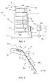
- FIG 4 shows a structure of the ladder arrangement 6 according to the invention in a strongly simplified manner.
- the ladders comprise at least one movable ladder part 8 and at least one fixed ladder part 9.
- the ladder parts comprise steps 8a and 9a having substantially the same step distribution T.
- the ladder parts 8 and 9 are arranged in succession and they may be interconnected with suitable support members in a manner allowing the movable ladder part 8 to be moved longitudinally relative to the fixed ladder part 9.
- the ladder parts 8 and 9 are superimposed in an overlapping portion 10.
- the movable ladder part 8 can be moved longitudinally S by means of one or more actuators 11, which may be connected directly or by means of suitable power transmission members to act on the movable ladder part 8.
- the actuator 11 may be a hydraulic or pneumatic cylinder.
- the actuator 11 may be a pressure medium driven motor arranged to act on the movable ladder part 8 by means of a toothed bar or the like. Furthermore, the actuator 11 may be an electric motor or any other power unit suitable for moving the ladder part 8. The actuator 11 may operate both as a transfer device and as a locking device.
- the upper end 30 of the ladder arrangement 6 may be fastened to the beam 2 in a fastening portion 31.
- the fastening portion 31 may be arranged in the vicinity of the person cage 3 at the upper end of the beam 2, enabling easy transfer from the ladder into the carriage.
- the ladder arrangement 6 comprises one or more sensors 12 for monitoring the mutual position of the steps 8a and 9a in the overlapping portion 10. Monitoring information can be transmitted from the sensor 12 to a control device 13 comprised by the ladder arrangement 6, the control device, in turn, being arranged to directly control the actuator 11 or a valve 14 or a corresponding adjustment member acting on the actuator 11.
- the steps 8a and 9a in the overlapping portion 10 may be at different points relative each other. This is illustrated by a step 15 shown with a dashed line.
- the movable ladder part 8 should be moved with the actuator 11 either upwards U or downwards V in such a manner that the steps 8a and 9a take the position shown by a solid line in Figure 4 .
- the control device 13 may be arranged to control the actuator 11 automatically to set the steps 8a and 9a at the same point.
- the sensor 12 indicates to the control device 13 when the steps 8a and 9a are at the same point.
- the actuator 11 is operated manually, for instance by controlling the actuator in a first direction or a second direction by means of push buttons 16 for transferring the ladder part 8.
- An indicator 17, such as a indicator lamp or a sound signal, for example, can be provided in connection with the control device 13 for indicating to the user when the steps 8a and 9a are correctly in the overlapping portion 10.
- Figure 5 further shows an embodiment for adjusting the movable part 8 of the ladder 6b.
- the actuator 11 may be arranged to move the third articulation 7 in direction S, enabling movement of the movable ladder part 8 relative to the fixed ladder part 9 in a manner allowing the steps in the overlapping portion of the ladder parts 8 and 9 to be arranged at substantially the same point.
- Figure 5 further shows that the third articulation 7 is closer by distance X to the outermost end of the beam 2 as compared with the second articulation 5. This being so, angle C between the first ladder 6a and the carriage 1 is always smaller than angle D between the first beam part 2a and the carriage 1. This allows the angle of ascent of the ladder part 6a to be rendered smaller, which naturally facilitates and speeds up climbing in the ladders.
- the second ladder 6b shown in Figures 1 to 3 and 5 may comprise a movable part and a fixed part and one or more actuators 11 for setting the steps 8a and 9a of the ladder parts substantially at the same point in the overlapping portion.
- the ladder arrangement shown in Figure 6 comprises a lower first ladder 6a and an upper second ladder 6b.
- the lower end of the first ladder 6a may be fastened to the carriage 1 of the person lifter by means of a fastening point 20.
- the outermost end 30, i.e. upper end, of the second ladder 6b may, in turn, be fastened to the upper end of the beam 2 by means of a fastening point 31.
- the second ladder 6b may comprise a turning part 22, which may be rotationally connected by means of an articulation 23 to a movable portion 24 in the second ladder 6b.
- the turning part 22 may further be connected by means of the articulation 7 to a movable portion 25 in the first ladder 6a.
- the actuator 11 which is not shown in Figure 6 by way of clarity, may be arranged to turn the turning part 22 in direction E, whereby the movable ladder parts 24, 25 move. The steps can then be set in place by turning the turning part 22.
- the lower part of the first ladder 6a may comprise a fixed ladder portion 26, which may be connected to the carriage 1 by means of an articulation 27.
- the outermost end of the second ladder 6b may comprise a fixed ladder portion 28.
- the movable ladder parts and the fixed ladder parts are arranged to glide telescopically relative to each other, which is illustrated by transverse lines 29 marked in Figure 6 .
- the ladder arrangement according to the invention can be applied to other kinds of beams than those shown in the figures.
- the beam may comprise a plurality of extendable and retractable beam parts articulated to each other or having a fixed length.
- the ladders may comprise a plurality of movable portions and, correspondingly, one or more fixed portions.
Landscapes
- Engineering & Computer Science (AREA)
- Mechanical Engineering (AREA)
- Structural Engineering (AREA)
- Life Sciences & Earth Sciences (AREA)
- Geology (AREA)
- Ladders (AREA)
Description
- The invention relates to a person lifter according to a preamble of
independent apparatus claim 1. - The invention still further relates to a method of using a person lifter provided with ladders, and disclosed in a preamble of
independent method claim 5. - Fire-fighting vehicles and corresponding rescue vehicles typically comprise a person lifter provided with ladders in a manner enabling climbing into a person cage or the like at the outermost end of the person lifter. The beam comprised by the person lifter can usually be extended and shortened, whereby the length of the ladders has to be able to change correspondingly. Accordingly, the ladders are typically arranged partly overlapping, and they are able to glide relative to each other when the beam is being moved. In order to enable climbing along the ladders, the steps of the ladders should be substantially at the same point in the overlapping portion. Accordingly, the steps have to be placed in position by changing the length of the beam. In this case, the position of the outermost end of the beam naturally changes and the entire beam has to be repositioned for getting the person cage into the original position. Consequently, the problem is the complex and slow use of the person lifter.
-
US-3584703-A discloses a hydraulic platform provided with a ladder arrangement, in accordance with the preamble ofclaim 1 and a method of using it in accordance with the preamble ofclaim 5. - The object of the present invention is to provide a new and improved person lifter, and a method of using a person lifter provided with ladders.
- The person lifter of the invention is characterized by the features of independent apparatus claim.
- The method of the invention is characterized by the features of independent method claim.
- The essential idea of the invention is that the ladder arrangement comprises one or more actuators arranged to move the movable portion comprised by the ladders in a manner allowing the steps of the overlapping ladder portions to be positioned substantially at the same point. The upper end of the ladder arrangement is arranged to remain in position when the steps are position in place by means of the actuator.
- An advantage is that the steps of the overlapping ladder parts can be placed at the same point without having to move the beam. This allows the person cage to be driven to the desired position and to be kept in place in this position during the setting of the steps. The actuator moves the movable portion of the ladders, but does not affect the upper end of the ladder arrangement. Accordingly, the invention speeds up and simplifies the driving in place of the person cage, which is a very important issue at least in rescue operations.
- An idea of an embodiment of the invention is that movement of the beam is prevented when the movable ladder part is being moved by means of the actuator.
- An idea of an embodiment of the invention is that the actuator is arranged to operate both as a transfer device and as a locking device of the movable ladder part. This way, several separate devices are not required for the transfer and locking.
- An idea of an embodiment of the invention is that the pressure medium-operated actuator, such as a hydraulic cylinder, for example, is arranged to move the movable ladder part.
- An idea of an embodiment of the invention is that the outermost part of the ladder arrangement, i.e. the upper end, is fastened immobile to the upper part of the beam. The mounting of the upper part of the ladder arrangement thus receives part of the load of the ladders. The actuator may be arranged to move the lowest portion of the ladder arrangement. Alternatively or in addition, some movable ladder part between the lowest ladder part and the immobile uppermost ladder part can be moved.
- An idea of an embodiment of the invention is that the outermost part, i.e. the upper end, of the ladder arrangement is fastened immobile to the upper part of the beam, and the lower part of the ladder arrangement is fastened immobile to the carriage of the lifter or to a corresponding support point. This being so, the actuator is arranged to move a movable ladder part between the ends of the ladder arrangement for placing the steps in position.
- An idea of an embodiment of the invention is that the person lifter is arranged on a movable carriage, which is a rescue vehicle.
- An idea of an embodiment of the invention is that the ladder arrangement comprises at least one sensor arranged to monitor the position of the steps in the overlapping portion of the ladder parts.
- An idea of an embodiment of the invention is that the ladder arrangement comprises at least one control unit arranged to control the actuator and to drive the movable ladder part automatically in such a manner that the steps in the overlapping portion are substantially at the same point.
- The invention will be described in more detail in the accompanying drawings, wherein
-
Figure 1 is a schematic side view of a person lifter according to the invention with the beam lifted to its uppermost position, -
Figure 2 schematically shows the person lifter shown inFigure 1 with the beam lifted to a horizontal position, -
Figure 3 schematically shows the person lifter shown inFigure 1 with the beam directed downwards, -
Figure 4 schematically shows the structure of a ladder arrangement according to the invention, -
Figure 5 schematically shows the principle of a second ladder arrangement according to the invention, and -
Figure 6 schematically shows still another ladder arrangement. - For the sake of clarity, the figures show some embodiments of the invention in a simplified manner. Like parts are denoted with the same reference numerals.
- The person lifter shown in
Figure 1 comprises acarriage 1, which can be a movable carriage, such as a fire-fighting vehicle or another rescue vehicle. Abeam 2 is arranged on thecarriage 1, the beam being movable in a manner enabling the driving of aperson cage 3 or the like at the outermost end of the beam to the desired place. Thebeam 2 may comprise afirst part 2a and asecond part 2b. Thefirst beam part 2a may be connected by means of afirst articulation 4 or the like to thecarriage 1 in a manner allowing thebeam 2 to be rotated in direction A. The outermost end of thefirst part 2a is provided with asecond articulation 5 or the like, and thesecond beam part 2b, connected thereto, can be rotated in direction B relative to thefirst part 2a. The length of thefirst part 2a may be fixed. Thesecond beam part 2b, in turn, may be telescopically extendable and retractable, enabling the movement of the person cage 3 by lengthening and shortening the length of thesecond part 2b and by rotating thebeam parts articulations - The person lifter also comprises a
ladder arrangement 6 in a manner allowing climbing from thecarriage 1 along the ladders to theperson cage 3 and back. On the other hand, thebeam 2 does not necessarily have to comprise aperson cage 3, but it may be provided with some other means, such as a fire-extinguishing medium nozzle. Theladder arrangement 6 may be arranged on the side of one flank of thebeam 2, as is illustrated inFigures 1 to 3 . The ladder arrangement may comprise afirst ladder 6a arranged in thefirst beam part 2a and asecond ladder 6b arranged in thesecond beam part 2b. Thefirst ladder 6a and thesecond ladder 6b may be interconnected by means of athird articulation 7. The articulation between theladders second beam part 2b, at a distance from thearticulation 5 between thebeam parts articulations first ladder 6a and thecarriage 1 is always smaller than the angle between thefirst beam part 2a and thecarriage 1, as can be seen inFigures 1 to 3 . This substantially facilitates and speeds up climbing in the ladders. When thebeam 2 is moved to different positions, the distance changes between the lower end of thefirst ladder 6a and thearticulation 7. Thefirst ladder 6a comprises at least two ladder parts arranged movable relative to each other. The ladder parts may be arranged to glide telescopically relative to each other, whereby the ladder parts enable a change in the length of thefirst ladder 6a when thebeam 2 is moved. -
Figure 4 shows a structure of theladder arrangement 6 according to the invention in a strongly simplified manner. The ladders comprise at least onemovable ladder part 8 and at least onefixed ladder part 9. The ladder parts comprisesteps ladder parts movable ladder part 8 to be moved longitudinally relative to the fixedladder part 9. Theladder parts portion 10. Themovable ladder part 8 can be moved longitudinally S by means of one ormore actuators 11, which may be connected directly or by means of suitable power transmission members to act on themovable ladder part 8. Theactuator 11 may be a hydraulic or pneumatic cylinder. Alternatively, theactuator 11 may be a pressure medium driven motor arranged to act on themovable ladder part 8 by means of a toothed bar or the like. Furthermore, theactuator 11 may be an electric motor or any other power unit suitable for moving theladder part 8. Theactuator 11 may operate both as a transfer device and as a locking device. Theupper end 30 of theladder arrangement 6 may be fastened to thebeam 2 in afastening portion 31. Thefastening portion 31 may be arranged in the vicinity of theperson cage 3 at the upper end of thebeam 2, enabling easy transfer from the ladder into the carriage. When steps are being set by means of theactuator 11, the position of theperson cage 3 and the position of theupper end 30 of the ladders remain unchanged, and thus their position does not have to be reset later. - The
ladder arrangement 6 comprises one ormore sensors 12 for monitoring the mutual position of thesteps portion 10. Monitoring information can be transmitted from thesensor 12 to acontrol device 13 comprised by theladder arrangement 6, the control device, in turn, being arranged to directly control theactuator 11 or avalve 14 or a corresponding adjustment member acting on theactuator 11. When thebeam 6 is driven to the desired place and position, thesteps portion 10 may be at different points relative each other. This is illustrated by astep 15 shown with a dashed line. In order to get the steps in the overlapping portion to substantially the same point relative to each other, themovable ladder part 8 should be moved with theactuator 11 either upwards U or downwards V in such a manner that thesteps Figure 4 . Thecontrol device 13 may be arranged to control theactuator 11 automatically to set thesteps sensor 12 indicates to thecontrol device 13 when thesteps actuator 11 is operated manually, for instance by controlling the actuator in a first direction or a second direction by means ofpush buttons 16 for transferring theladder part 8. Anindicator 17, such as a indicator lamp or a sound signal, for example, can be provided in connection with thecontrol device 13 for indicating to the user when thesteps portion 10. -
Figure 5 further shows an embodiment for adjusting themovable part 8 of theladder 6b. Theactuator 11 may be arranged to move thethird articulation 7 in direction S, enabling movement of themovable ladder part 8 relative to the fixedladder part 9 in a manner allowing the steps in the overlapping portion of theladder parts Figure 5 further shows that thethird articulation 7 is closer by distance X to the outermost end of thebeam 2 as compared with thesecond articulation 5. This being so, angle C between thefirst ladder 6a and thecarriage 1 is always smaller than angle D between thefirst beam part 2a and thecarriage 1. This allows the angle of ascent of theladder part 6a to be rendered smaller, which naturally facilitates and speeds up climbing in the ladders. - Let it be mentioned that, in the same way as the
first ladder 6a, thesecond ladder 6b shown inFigures 1 to 3 and5 may comprise a movable part and a fixed part and one ormore actuators 11 for setting thesteps - The ladder arrangement shown in
Figure 6 comprises a lowerfirst ladder 6a and an uppersecond ladder 6b. The lower end of thefirst ladder 6a may be fastened to thecarriage 1 of the person lifter by means of afastening point 20. Theoutermost end 30, i.e. upper end, of thesecond ladder 6b may, in turn, be fastened to the upper end of thebeam 2 by means of afastening point 31. Thesecond ladder 6b may comprise a turningpart 22, which may be rotationally connected by means of anarticulation 23 to amovable portion 24 in thesecond ladder 6b. The turningpart 22 may further be connected by means of thearticulation 7 to amovable portion 25 in thefirst ladder 6a. Theactuator 11, which is not shown inFigure 6 by way of clarity, may be arranged to turn the turningpart 22 in direction E, whereby themovable ladder parts part 22. The lower part of thefirst ladder 6a may comprise a fixedladder portion 26, which may be connected to thecarriage 1 by means of anarticulation 27. Furthermore, the outermost end of thesecond ladder 6b may comprise a fixedladder portion 28. In bothladders transverse lines 29 marked inFigure 6 . - The ladder arrangement according to the invention can be applied to other kinds of beams than those shown in the figures. The beam may comprise a plurality of extendable and retractable beam parts articulated to each other or having a fixed length. Furthermore, the ladders may comprise a plurality of movable portions and, correspondingly, one or more fixed portions.
- The characteristics described in the present application can also be applied separately and, on the other hand, other combinations than those shown in the figures by way of example can be constructed from the characteristics.
- The drawings and the related description are only intended to illustrate the idea of the invention. The details of the invention may vary within the scope of the claims.
Claims (8)
- A person lifter comprising:a carriage (1);a movable beam (2);a first beam part (2a) connected to the carriage (1) by means of a first articulation (4) and movable relative to the first articulation (4), and the first part (2a) having a fixed length;a second beam part (2b) connected to an outermost end of the first beam part (2a) by means of a second articulation (5), the second part (2b) being extendable and retractable;a ladder arrangement (6) comprising a first ladder (6a) arranged on the first beam part (2a) and a second ladder (6b) arranged on the second beam part (2b), the first ladder (6a) and the second ladder (6b) comprising a plurality of steps (8a, 9a) having a predetermined step distribution (T), the first ladder (6a) comprising at least one fixed ladder part (9) and at least one movable ladder part (8), the ladder parts (8, 9) being arranged in succession and partly overlapping relative to each other,and wherein an upper end (30) of the ladder arrangement (6) is fastened to an upper part of the beam (2),and the lower part of the ladder arrangement is fastened immobile to the carriage of the lifter or to a corresponding support point, the first ladder (6a) and the second ladder (6b) are interconnected by means of a third articulation (7);characterized in thatthe third articulation (7) is fastened to the second beam part (2b) such that the third articulation (7) is located at a distance (X) from the second articulation (5), whereby an angle (C) between the first ladder (6a) and the carriage (1) is always smaller than an angle (D) between the first beam part (2b) and the carriage (1);the first ladder (6a) comprises at least one actuator (11) for positioning the movable ladder part (8) relative to the fixed ladder part (9) such that the steps (8a, 9a) in the overlapping portion (10) of the ladder parts (8, 9) can be positioned substantially at the same point by moving the movable part (8);the upper end (30) of the ladder arrangement (6) is arranged to remain substantially immobile when the actuator (11) is being used.
- A person lifter as claimed in claim 1, characterized in that
the actuator (11) is a hydraulic cylinder. - A person lifter as claimed in claim 1 or 2, characterized in that
an upper end of the second beam part (6b) comprises a person cage (3). - A person lifter as claimed in any one of the preceding claims, characterized in that
the movement of the beam (2) is prevented when the actuator (11) connected to the movable part (8) of the ladders is being used. - A method of using a person lifter provided with ladders,
the person lifter comprising at least a carriage (1), a movable beam (2) and a ladder arrangement (6), the ladder arrangement (6) comprising a movable ladder part (8) and a fixed ladder part (9) arranged in succession and partly overlapping relative to each other, and an upper end (30) of the ladder arrangement is fastened to an upper part of the beam,
and the lower part of the ladder arrangement is fastened immobile to the carriage of the lifter or to a corresponding support point,
the method comprising:moving the beam (2) for driving an upper end of the beam into the desired position, andplacing steps (8a, 9a) of the movable ladder part (8) and the fixed ladder part (9) substantially at the same point in the overlapping portion (10) of the ladder parts,characterized bymoving the movable ladder part (8) by means of at least one actuator (11) relative to the fixed ladder part (9) for placing the steps (8a, 9a) substantially at the same point in the overlapping portion (10) of the ladder parts; andkeeping the beam (2) and an upper end (30) of the ladder arrangement (6) substantially immobile when the actuator (11) is being used. - A method as claimed in claim 5, characterized by
monitoring the mutual position of the steps (8a, 9a) of the ladder parts (8, 9) on the overlapping portion (10) of the ladder parts by means of at least one sensor (12),
transmitting monitoring information from the sensor (12) to a control device (13), and
automatically driving the steps (8a, 9a) of the ladder parts (8, 9) by means of the control device (13) at a substantially same point in the overlapping portion (10). - A method as claimed in claim 5 or 6, characterized by
using the actuator (11) to move only one movable ladder part (8) lowest in the ladder arrangement (6). - A method as claimed in claim 5 or 6, characterized by
using the actuator (11) to move an articulation (7) that connects the first ladder (6a) and the second ladder (6b) comprised by the ladder arrangement (6), the movement of the articulation (7) being arranged to cause the movement of the movable portion (8) of the first ladder (6a) relative to the fixed portion (9), and the movement of the movable portion (8) of the second ladder (6b) relative to the fixed portion (9).
Priority Applications (1)
| Application Number | Priority Date | Filing Date | Title |
|---|---|---|---|
| PL05757931T PL1774131T3 (en) | 2004-06-29 | 2005-06-28 | Ladder arrangement, person lifter and method of using a person lifter |
Applications Claiming Priority (2)
| Application Number | Priority Date | Filing Date | Title |
|---|---|---|---|
| FI20045249A FI123891B (en) | 2004-06-29 | 2004-06-29 | The aerial platform |
| PCT/FI2005/050241 WO2006000645A1 (en) | 2004-06-29 | 2005-06-28 | Ladder arrangement, person lifter and method of using a person lifter |
Publications (3)
| Publication Number | Publication Date |
|---|---|
| EP1774131A1 EP1774131A1 (en) | 2007-04-18 |
| EP1774131A4 EP1774131A4 (en) | 2012-01-11 |
| EP1774131B1 true EP1774131B1 (en) | 2013-11-06 |
Family
ID=32524623
Family Applications (1)
| Application Number | Title | Priority Date | Filing Date |
|---|---|---|---|
| EP05757931.0A Expired - Lifetime EP1774131B1 (en) | 2004-06-29 | 2005-06-28 | Ladder arrangement, person lifter and method of using a person lifter |
Country Status (4)
| Country | Link |
|---|---|
| EP (1) | EP1774131B1 (en) |
| FI (1) | FI123891B (en) |
| PL (1) | PL1774131T3 (en) |
| WO (1) | WO2006000645A1 (en) |
Families Citing this family (1)
| Publication number | Priority date | Publication date | Assignee | Title |
|---|---|---|---|---|
| US20070076878A1 (en) | 2005-09-30 | 2007-04-05 | Nortel Networks Limited | Any-point-to-any-point ("AP2AP") quantum key distribution protocol for optical ring network |
Family Cites Families (4)
| Publication number | Priority date | Publication date | Assignee | Title |
|---|---|---|---|---|
| DE1292370B (en) * | 1959-11-11 | 1969-04-10 | Kloeckner Humboldt Deutz Ag | Extension ladder |
| GB1248611A (en) * | 1968-06-07 | 1971-10-06 | Simon Eng Dudley Ltd | Improvements in or relating to vehicle mounted hydraulic platforms |
| FR2501390A1 (en) * | 1981-03-05 | 1982-09-10 | Camiva | MICROPROCESSOR CONTROL DEVICE FOR DEPLOYABLE ORIENTABLE SCALE OR SIMILAR ELEVATOR ARM |
| DE29800754U1 (en) * | 1998-01-17 | 1998-04-16 | Wumag Elevant Gmbh & Co Kg | Rescue or work leader |
-
2004
- 2004-06-29 FI FI20045249A patent/FI123891B/en active IP Right Grant
-
2005
- 2005-06-28 EP EP05757931.0A patent/EP1774131B1/en not_active Expired - Lifetime
- 2005-06-28 PL PL05757931T patent/PL1774131T3/en unknown
- 2005-06-28 WO PCT/FI2005/050241 patent/WO2006000645A1/en not_active Ceased
Also Published As
| Publication number | Publication date |
|---|---|
| FI123891B (en) | 2013-12-13 |
| EP1774131A1 (en) | 2007-04-18 |
| WO2006000645A1 (en) | 2006-01-05 |
| EP1774131A4 (en) | 2012-01-11 |
| FI20045249L (en) | 2005-12-30 |
| FI20045249A0 (en) | 2004-06-29 |
| PL1774131T3 (en) | 2014-05-30 |
Similar Documents
| Publication | Publication Date | Title |
|---|---|---|
| US11565922B2 (en) | Remote controlled telehandler | |
| EP3424869B1 (en) | System for stabilizing self-propelled operating machines | |
| US8720709B2 (en) | Crane and method for erecting the crane | |
| CA2685881C (en) | Adjusting mechanism for a winch | |
| US20160221804A1 (en) | Ballast Apparatus and Crane, in particular Crawler-Mounted Crane | |
| EP3345861B1 (en) | Lifting device for lifting a vehicle with a locking system and lifting system and method therefor | |
| US20210402930A1 (en) | Earth working machine having a climbing device that is variable in length and has a plurality of different climb-ready operating positions | |
| EP3808588B1 (en) | Improved system for displaying information | |
| JP6577794B2 (en) | Communication device for work equipment | |
| CN113382946A (en) | Hang off ground controlling means and hoist | |
| US7341418B2 (en) | Vehicle equipped with lift device and lift device | |
| WO1999061748A1 (en) | Boom arrangement for rock drilling apparatus | |
| EP1774131A1 (en) | Ladder arrangement, person lifter and method of using a person lifter | |
| US20240375918A1 (en) | Crane with derrick ballast | |
| FI122068B (en) | Ladder for ski lift, ski lift and method for using the ski lift ladder | |
| US20250026622A1 (en) | Safety system for working machine | |
| JP4163879B2 (en) | Crane hook horizontal movement control device | |
| US20240327175A1 (en) | Crane with luffing aid device and method for luffing such a crane | |
| JP2000053397A (en) | Aerial work vehicle | |
| EP0579181A1 (en) | A central control unit for controllable placement supports of a fire-fighting vehicle with a turntable ladder or the like | |
| EP4620891A1 (en) | Stabilising system for self-propelled operating machines | |
| EP3587727B1 (en) | Ladder system for rescue vehicles | |
| EP2558404B1 (en) | Boom, personnel hoist, and method for using personnel hoist | |
| JPH0138758B2 (en) | ||
| JP3836288B2 (en) | Control equipment for aerial work platforms |
Legal Events
| Date | Code | Title | Description |
|---|---|---|---|
| PUAI | Public reference made under article 153(3) epc to a published international application that has entered the european phase |
Free format text: ORIGINAL CODE: 0009012 |
|
| 17P | Request for examination filed |
Effective date: 20070116 |
|
| AK | Designated contracting states |
Kind code of ref document: A1 Designated state(s): AT BE BG CH CY CZ DE DK EE ES FI FR GB GR HU IE IS IT LI LT LU MC NL PL PT RO SE SI SK TR |
|
| DAX | Request for extension of the european patent (deleted) | ||
| RIC1 | Information provided on ipc code assigned before grant |
Ipc: E06C 1/08 20060101ALI20111020BHEP Ipc: B66F 11/04 20060101ALI20111020BHEP Ipc: E06C 1/30 20060101ALI20111020BHEP Ipc: E06C 1/10 20060101ALI20111020BHEP Ipc: E06C 5/06 20060101AFI20111020BHEP |
|
| RIC1 | Information provided on ipc code assigned before grant |
Ipc: E06C 1/30 20060101ALI20111101BHEP Ipc: E06C 5/06 20060101AFI20111101BHEP Ipc: E06C 1/08 20060101ALI20111101BHEP Ipc: B66F 11/04 20060101ALI20111101BHEP Ipc: E06C 1/10 20060101ALI20111101BHEP |
|
| RIC1 | Information provided on ipc code assigned before grant |
Ipc: E06C 1/30 20060101ALI20111118BHEP Ipc: E06C 5/06 20060101AFI20111118BHEP Ipc: E06C 1/10 20060101ALI20111118BHEP Ipc: B66F 11/04 20060101ALI20111118BHEP Ipc: E06C 1/08 20060101ALI20111118BHEP |
|
| RIC1 | Information provided on ipc code assigned before grant |
Ipc: E06C 5/06 20060101AFI20111124BHEP Ipc: B66F 11/04 20060101ALI20111124BHEP Ipc: E06C 1/30 20060101ALI20111124BHEP Ipc: E06C 1/08 20060101ALI20111124BHEP Ipc: E06C 1/10 20060101ALI20111124BHEP |
|
| A4 | Supplementary search report drawn up and despatched |
Effective date: 20111213 |
|
| RIC1 | Information provided on ipc code assigned before grant |
Ipc: E06C 1/10 20060101ALI20111206BHEP Ipc: B66F 11/04 20060101ALI20111206BHEP Ipc: E06C 5/06 20060101AFI20111206BHEP Ipc: E06C 1/30 20060101ALI20111206BHEP Ipc: E06C 1/08 20060101ALI20111206BHEP |
|
| 17Q | First examination report despatched |
Effective date: 20120327 |
|
| REG | Reference to a national code |
Ref country code: DE Ref legal event code: R079 Ref document number: 602005041774 Country of ref document: DE Free format text: PREVIOUS MAIN CLASS: E06C0005060000 Ipc: B66F0011040000 |
|
| RIC1 | Information provided on ipc code assigned before grant |
Ipc: B66F 11/04 20060101AFI20130417BHEP Ipc: E06C 1/10 20060101ALI20130417BHEP Ipc: E06C 5/06 20060101ALI20130417BHEP |
|
| GRAP | Despatch of communication of intention to grant a patent |
Free format text: ORIGINAL CODE: EPIDOSNIGR1 |
|
| INTG | Intention to grant announced |
Effective date: 20130605 |
|
| GRAS | Grant fee paid |
Free format text: ORIGINAL CODE: EPIDOSNIGR3 |
|
| GRAA | (expected) grant |
Free format text: ORIGINAL CODE: 0009210 |
|
| AK | Designated contracting states |
Kind code of ref document: B1 Designated state(s): AT BE BG CH CY CZ DE DK EE ES FI FR GB GR HU IE IS IT LI LT LU MC NL PL PT RO SE SI SK TR |
|
| REG | Reference to a national code |
Ref country code: GB Ref legal event code: FG4D |
|
| REG | Reference to a national code |
Ref country code: CH Ref legal event code: EP |
|
| REG | Reference to a national code |
Ref country code: AT Ref legal event code: REF Ref document number: 639325 Country of ref document: AT Kind code of ref document: T Effective date: 20131215 |
|
| REG | Reference to a national code |
Ref country code: IE Ref legal event code: FG4D |
|
| REG | Reference to a national code |
Ref country code: DE Ref legal event code: R096 Ref document number: 602005041774 Country of ref document: DE Effective date: 20140102 |
|
| REG | Reference to a national code |
Ref country code: NL Ref legal event code: T3 |
|
| REG | Reference to a national code |
Ref country code: SE Ref legal event code: TRGR |
|
| REG | Reference to a national code |
Ref country code: LT Ref legal event code: MG4D |
|
| PG25 | Lapsed in a contracting state [announced via postgrant information from national office to epo] |
Ref country code: IS Free format text: LAPSE BECAUSE OF FAILURE TO SUBMIT A TRANSLATION OF THE DESCRIPTION OR TO PAY THE FEE WITHIN THE PRESCRIBED TIME-LIMIT Effective date: 20140306 Ref country code: LT Free format text: LAPSE BECAUSE OF FAILURE TO SUBMIT A TRANSLATION OF THE DESCRIPTION OR TO PAY THE FEE WITHIN THE PRESCRIBED TIME-LIMIT Effective date: 20131106 Ref country code: FI Free format text: LAPSE BECAUSE OF FAILURE TO SUBMIT A TRANSLATION OF THE DESCRIPTION OR TO PAY THE FEE WITHIN THE PRESCRIBED TIME-LIMIT Effective date: 20131106 |
|
| PG25 | Lapsed in a contracting state [announced via postgrant information from national office to epo] |
Ref country code: ES Free format text: LAPSE BECAUSE OF FAILURE TO SUBMIT A TRANSLATION OF THE DESCRIPTION OR TO PAY THE FEE WITHIN THE PRESCRIBED TIME-LIMIT Effective date: 20131106 |
|
| REG | Reference to a national code |
Ref country code: PL Ref legal event code: T3 |
|
| PG25 | Lapsed in a contracting state [announced via postgrant information from national office to epo] |
Ref country code: PT Free format text: LAPSE BECAUSE OF FAILURE TO SUBMIT A TRANSLATION OF THE DESCRIPTION OR TO PAY THE FEE WITHIN THE PRESCRIBED TIME-LIMIT Effective date: 20140306 |
|
| PG25 | Lapsed in a contracting state [announced via postgrant information from national office to epo] |
Ref country code: EE Free format text: LAPSE BECAUSE OF FAILURE TO SUBMIT A TRANSLATION OF THE DESCRIPTION OR TO PAY THE FEE WITHIN THE PRESCRIBED TIME-LIMIT Effective date: 20131106 |
|
| REG | Reference to a national code |
Ref country code: DE Ref legal event code: R097 Ref document number: 602005041774 Country of ref document: DE |
|
| PG25 | Lapsed in a contracting state [announced via postgrant information from national office to epo] |
Ref country code: SK Free format text: LAPSE BECAUSE OF FAILURE TO SUBMIT A TRANSLATION OF THE DESCRIPTION OR TO PAY THE FEE WITHIN THE PRESCRIBED TIME-LIMIT Effective date: 20131106 Ref country code: IT Free format text: LAPSE BECAUSE OF FAILURE TO SUBMIT A TRANSLATION OF THE DESCRIPTION OR TO PAY THE FEE WITHIN THE PRESCRIBED TIME-LIMIT Effective date: 20131106 Ref country code: RO Free format text: LAPSE BECAUSE OF FAILURE TO SUBMIT A TRANSLATION OF THE DESCRIPTION OR TO PAY THE FEE WITHIN THE PRESCRIBED TIME-LIMIT Effective date: 20131106 Ref country code: CZ Free format text: LAPSE BECAUSE OF FAILURE TO SUBMIT A TRANSLATION OF THE DESCRIPTION OR TO PAY THE FEE WITHIN THE PRESCRIBED TIME-LIMIT Effective date: 20131106 |
|
| PLBE | No opposition filed within time limit |
Free format text: ORIGINAL CODE: 0009261 |
|
| STAA | Information on the status of an ep patent application or granted ep patent |
Free format text: STATUS: NO OPPOSITION FILED WITHIN TIME LIMIT |
|
| PG25 | Lapsed in a contracting state [announced via postgrant information from national office to epo] |
Ref country code: DK Free format text: LAPSE BECAUSE OF FAILURE TO SUBMIT A TRANSLATION OF THE DESCRIPTION OR TO PAY THE FEE WITHIN THE PRESCRIBED TIME-LIMIT Effective date: 20131106 |
|
| 26N | No opposition filed |
Effective date: 20140807 |
|
| REG | Reference to a national code |
Ref country code: DE Ref legal event code: R097 Ref document number: 602005041774 Country of ref document: DE Effective date: 20140807 |
|
| PG25 | Lapsed in a contracting state [announced via postgrant information from national office to epo] |
Ref country code: MC Free format text: LAPSE BECAUSE OF FAILURE TO SUBMIT A TRANSLATION OF THE DESCRIPTION OR TO PAY THE FEE WITHIN THE PRESCRIBED TIME-LIMIT Effective date: 20131106 Ref country code: LU Free format text: LAPSE BECAUSE OF FAILURE TO SUBMIT A TRANSLATION OF THE DESCRIPTION OR TO PAY THE FEE WITHIN THE PRESCRIBED TIME-LIMIT Effective date: 20140628 |
|
| REG | Reference to a national code |
Ref country code: CH Ref legal event code: PL |
|
| PG25 | Lapsed in a contracting state [announced via postgrant information from national office to epo] |
Ref country code: SI Free format text: LAPSE BECAUSE OF FAILURE TO SUBMIT A TRANSLATION OF THE DESCRIPTION OR TO PAY THE FEE WITHIN THE PRESCRIBED TIME-LIMIT Effective date: 20131106 |
|
| REG | Reference to a national code |
Ref country code: IE Ref legal event code: MM4A |
|
| PG25 | Lapsed in a contracting state [announced via postgrant information from national office to epo] |
Ref country code: CH Free format text: LAPSE BECAUSE OF NON-PAYMENT OF DUE FEES Effective date: 20140630 Ref country code: IE Free format text: LAPSE BECAUSE OF NON-PAYMENT OF DUE FEES Effective date: 20140628 Ref country code: LI Free format text: LAPSE BECAUSE OF NON-PAYMENT OF DUE FEES Effective date: 20140630 |
|
| PG25 | Lapsed in a contracting state [announced via postgrant information from national office to epo] |
Ref country code: BG Free format text: LAPSE BECAUSE OF FAILURE TO SUBMIT A TRANSLATION OF THE DESCRIPTION OR TO PAY THE FEE WITHIN THE PRESCRIBED TIME-LIMIT Effective date: 20131106 |
|
| PG25 | Lapsed in a contracting state [announced via postgrant information from national office to epo] |
Ref country code: CY Free format text: LAPSE BECAUSE OF FAILURE TO SUBMIT A TRANSLATION OF THE DESCRIPTION OR TO PAY THE FEE WITHIN THE PRESCRIBED TIME-LIMIT Effective date: 20131106 Ref country code: GR Free format text: LAPSE BECAUSE OF FAILURE TO SUBMIT A TRANSLATION OF THE DESCRIPTION OR TO PAY THE FEE WITHIN THE PRESCRIBED TIME-LIMIT Effective date: 20140207 |
|
| REG | Reference to a national code |
Ref country code: FR Ref legal event code: PLFP Year of fee payment: 12 |
|
| PG25 | Lapsed in a contracting state [announced via postgrant information from national office to epo] |
Ref country code: HU Free format text: LAPSE BECAUSE OF FAILURE TO SUBMIT A TRANSLATION OF THE DESCRIPTION OR TO PAY THE FEE WITHIN THE PRESCRIBED TIME-LIMIT; INVALID AB INITIO Effective date: 20050628 Ref country code: TR Free format text: LAPSE BECAUSE OF FAILURE TO SUBMIT A TRANSLATION OF THE DESCRIPTION OR TO PAY THE FEE WITHIN THE PRESCRIBED TIME-LIMIT Effective date: 20131106 |
|
| REG | Reference to a national code |
Ref country code: FR Ref legal event code: PLFP Year of fee payment: 13 |
|
| REG | Reference to a national code |
Ref country code: FR Ref legal event code: PLFP Year of fee payment: 14 |
|
| PGFP | Annual fee paid to national office [announced via postgrant information from national office to epo] |
Ref country code: SE Payment date: 20220623 Year of fee payment: 18 Ref country code: NL Payment date: 20220630 Year of fee payment: 18 Ref country code: GB Payment date: 20220617 Year of fee payment: 18 Ref country code: DE Payment date: 20220621 Year of fee payment: 18 |
|
| PGFP | Annual fee paid to national office [announced via postgrant information from national office to epo] |
Ref country code: PL Payment date: 20220607 Year of fee payment: 18 Ref country code: BE Payment date: 20220613 Year of fee payment: 18 Ref country code: AT Payment date: 20220621 Year of fee payment: 18 |
|
| PGFP | Annual fee paid to national office [announced via postgrant information from national office to epo] |
Ref country code: FR Payment date: 20220614 Year of fee payment: 18 |
|
| REG | Reference to a national code |
Ref country code: DE Ref legal event code: R119 Ref document number: 602005041774 Country of ref document: DE |
|
| REG | Reference to a national code |
Ref country code: SE Ref legal event code: EUG |
|
| REG | Reference to a national code |
Ref country code: NL Ref legal event code: MM Effective date: 20230701 |
|
| REG | Reference to a national code |
Ref country code: AT Ref legal event code: MM01 Ref document number: 639325 Country of ref document: AT Kind code of ref document: T Effective date: 20230628 |
|
| REG | Reference to a national code |
Ref country code: BE Ref legal event code: MM Effective date: 20230630 |
|
| GBPC | Gb: european patent ceased through non-payment of renewal fee |
Effective date: 20230628 |
|
| PG25 | Lapsed in a contracting state [announced via postgrant information from national office to epo] |
Ref country code: NL Free format text: LAPSE BECAUSE OF NON-PAYMENT OF DUE FEES Effective date: 20230701 |
|
| PG25 | Lapsed in a contracting state [announced via postgrant information from national office to epo] |
Ref country code: AT Free format text: LAPSE BECAUSE OF NON-PAYMENT OF DUE FEES Effective date: 20230628 |
|
| PG25 | Lapsed in a contracting state [announced via postgrant information from national office to epo] |
Ref country code: DE Free format text: LAPSE BECAUSE OF NON-PAYMENT OF DUE FEES Effective date: 20240103 Ref country code: AT Free format text: LAPSE BECAUSE OF NON-PAYMENT OF DUE FEES Effective date: 20230628 Ref country code: GB Free format text: LAPSE BECAUSE OF NON-PAYMENT OF DUE FEES Effective date: 20230628 |
|
| PG25 | Lapsed in a contracting state [announced via postgrant information from national office to epo] |
Ref country code: SE Free format text: LAPSE BECAUSE OF NON-PAYMENT OF DUE FEES Effective date: 20230629 Ref country code: FR Free format text: LAPSE BECAUSE OF NON-PAYMENT OF DUE FEES Effective date: 20230630 Ref country code: BE Free format text: LAPSE BECAUSE OF NON-PAYMENT OF DUE FEES Effective date: 20230630 |
|
| PG25 | Lapsed in a contracting state [announced via postgrant information from national office to epo] |
Ref country code: PL Free format text: LAPSE BECAUSE OF NON-PAYMENT OF DUE FEES Effective date: 20230628 |
|
| PG25 | Lapsed in a contracting state [announced via postgrant information from national office to epo] |
Ref country code: PL Free format text: LAPSE BECAUSE OF NON-PAYMENT OF DUE FEES Effective date: 20230628 |