EP1773199B1 - Method for producing a three-dimensional digital x-ray image - Google Patents
Method for producing a three-dimensional digital x-ray image Download PDFInfo
- Publication number
- EP1773199B1 EP1773199B1 EP04742160A EP04742160A EP1773199B1 EP 1773199 B1 EP1773199 B1 EP 1773199B1 EP 04742160 A EP04742160 A EP 04742160A EP 04742160 A EP04742160 A EP 04742160A EP 1773199 B1 EP1773199 B1 EP 1773199B1
- Authority
- EP
- European Patent Office
- Prior art keywords
- ray
- taken
- image
- imaging
- digital
- Prior art date
- Legal status (The legal status is an assumption and is not a legal conclusion. Google has not performed a legal analysis and makes no representation as to the accuracy of the status listed.)
- Active
Links
- 238000004519 manufacturing process Methods 0.000 title claims abstract description 4
- 238000003384 imaging method Methods 0.000 claims abstract description 22
- 238000000034 method Methods 0.000 claims abstract description 17
- 230000005855 radiation Effects 0.000 claims description 5
- 238000003325 tomography Methods 0.000 description 4
- 238000009877 rendering Methods 0.000 description 2
- 230000003068 static effect Effects 0.000 description 2
- 210000001519 tissue Anatomy 0.000 description 2
- 238000004364 calculation method Methods 0.000 description 1
- 238000002591 computed tomography Methods 0.000 description 1
- 238000007796 conventional method Methods 0.000 description 1
- 238000009607 mammography Methods 0.000 description 1
Images

Classifications
-
- G—PHYSICS
- G06—COMPUTING; CALCULATING OR COUNTING
- G06T—IMAGE DATA PROCESSING OR GENERATION, IN GENERAL
- G06T11/00—2D [Two Dimensional] image generation
- G06T11/003—Reconstruction from projections, e.g. tomography
- G06T11/005—Specific pre-processing for tomographic reconstruction, e.g. calibration, source positioning, rebinning, scatter correction, retrospective gating
-
- A—HUMAN NECESSITIES
- A61—MEDICAL OR VETERINARY SCIENCE; HYGIENE
- A61B—DIAGNOSIS; SURGERY; IDENTIFICATION
- A61B6/00—Apparatus for radiation diagnosis, e.g. combined with radiation therapy equipment
- A61B6/02—Devices for diagnosis sequentially in different planes; Stereoscopic radiation diagnosis
- A61B6/025—Tomosynthesis
-
- A61B6/51—
-
- G—PHYSICS
- G06—COMPUTING; CALCULATING OR COUNTING
- G06T—IMAGE DATA PROCESSING OR GENERATION, IN GENERAL
- G06T2211/00—Image generation
- G06T2211/40—Computed tomography
- G06T2211/436—Limited angle
Definitions
- the invention relates to a method for producing a three-dimensional (3D) digital x-ray image by using digital x-ray images taken of the object from at least two different directions as input for a reconstruction algorithm.
- a reconstruction algorithm refers to an algorithm by means of which two-dimensional or three-dimensional x-ray image information on the object being imaged is reconstructed, that is, produced.
- the input used for a reconstruction algorithm in 3D x-ray imaging consists of a selection of projections taken from different directions, giving as a result a three-dimensional voxel representation of the tissue being imaged.
- US patent no. 6,611,575 B1 (Assignee General Electric Company) describes three-dimensional imaging using projections taken from different directions as a starting point, the projections being entered in the reconstruction algorithm in the form of spaced-apart planar images. These planar images are then used as input for the chosen 3D imaging method.
- the imaging method may be, for example, Volume Rendering or Surface Rendering or a combination of the two.
- Tomosynthetic slice images can be produced by any of the following methods:
- the aim of the present invention is to provide a method by means of which the artefacts in a tomographic 3D image can be eliminated and, in addition, the image quality be improved in areas where conventional 3D imaging based on projection imaging is insufficient, for example, in longitudinal imaging of the jaw bone.
- the method according to the invention is characterised in that in the method, at least one of the images used as input in the method is taken as a tomosynthetic slice image of a region of interest in the object of imaging.
- Figure 1 shows diagrammatically the principle of conventional tomosynthetic imaging.
- Reference numeral 1 denotes the x-ray source
- reference numeral 2 the detector receiving the radiation that has passed through the object of imaging 3
- reference numeral 4 the in-focus plane. Moving the radiation source 1 and the detector 2 simultaneously, at the same speed, in opposite directions will produce sharp image areas on the in-focus plane 4, whereas distant objects become blurred.
- Figure 2 shows another conventional method for implementing tomosynthetic imaging. In this method, the x-ray source 1 and the detector 2 are at a fixed distance from one another, turning as an integrated unit around the in-focus plane 4.
- Figure 3 shows diagrammatically a method of implementation according to the invention.
- a tomosynthetic slice image along the corresponding in-focus planes 4a, 4b and 4c, which slice images are then used as input for a tomographic, 3D reconstruction algorithm.
- a tomosynthetic slice image means, for example, a projection.
- Objects 6 outside the region 5 are blurred out of the images.
- Slice images can be taken from various directions and as input for a reconstruction algorithm can also be used projections taken from one or more different directions.
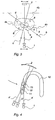
- Figure 4 shows diagrammatically the imaging of the longitudinal slices of the jaw bone.
- the method according to the invention can be used with any digital x-ray machine, such as a panoramic machine, mammography machine, an intraoral machine or a surgical C arc.
- a digital x-ray machine such as a panoramic machine, mammography machine, an intraoral machine or a surgical C arc.
- the device When taking projections with a device revolving around the object being imaged, the device having an x-ray source in one arm and a detector receiving x-radiation in the other arm opposite the object being imaged, it is possible to take images while the machine is moving, instead of static projections. This allows for the imaging speed to be increased, because the machine does not need to be stopped during imaging, and also objects at a distance from the region of interest are blurred.
- the degree of blurring can be adjusted with the exposure time and the speed of rotation. A longer exposure time can be used if necessary, which will reduce the power requirement of the x-ray source.
Abstract
Description
- The invention relates to a method for producing a three-dimensional (3D) digital x-ray image by using digital x-ray images taken of the object from at least two different directions as input for a reconstruction algorithm. A reconstruction algorithm refers to an algorithm by means of which two-dimensional or three-dimensional x-ray image information on the object being imaged is reconstructed, that is, produced.
- Conventionally, the input used for a reconstruction algorithm in 3D x-ray imaging consists of a selection of projections taken from different directions, giving as a result a three-dimensional voxel representation of the tissue being imaged. For example,
US patent no. 6,611,575 B1 (Assignee General Electric Company) describes three-dimensional imaging using projections taken from different directions as a starting point, the projections being entered in the reconstruction algorithm in the form of spaced-apart planar images. These planar images are then used as input for the chosen 3D imaging method. The imaging method may be, for example, Volume Rendering or Surface Rendering or a combination of the two. - It is often necessary to select a region of interest (ROI) within the object and to image each projection so that only the ROI is shown in the image. Reasons for this are the minimisation of the radiation dosage and the size limitations of the detector. This type of 3D imaging is called local tomography. The problem with local tomography is that objects at a distance from the ROI can be seen in the projections and cause artefacts (errors due to calculation) in the reconstruction.
- A technique long since known by dentists and based on simple local tomography is tomosynthetic imaging, in which a two-dimensional slice inside a tissue is imaged accurately and areas at a distance from the slice are shown unclearly. Tomosynthetic slice images can be produced by any of the following methods:
- a) By moving the film/detector and radiation source during imaging, which blurs objects at a distance from the in-focus plane and images objects on the in-focus plane sharply.
- b) By taking a series of static images, which are appropriately moved and summed to produce slice images corresponding approximately to those produced under a). ,
- c) By combining a) and b): a series of slightly blurred slice images complying with a) are taken, which are then moved and summed according to b).
- The aim of the present invention is to provide a method by means of which the artefacts in a tomographic 3D image can be eliminated and, in addition, the image quality be improved in areas where conventional 3D imaging based on projection imaging is insufficient, for example, in longitudinal imaging of the jaw bone. To achieve this aim, the method according to the invention is characterised in that in the method, at least one of the images used as input in the method is taken as a tomosynthetic slice image of a region of interest in the object of imaging.
- The invention is described in greater detail in the following, with reference to the accompanying drawings, in which:
- Figure 1
- shows a diagrammatic view in principle of the implementation of tomosynthetic imaging,
- Figure 2
- shows a diagrammatic view in principle of another implementation of tomosynthetic imaging, and
- Figure 3
- shows a diagrammatic view in principle of an implementation of the method according to the invention.
-
Figure 1 shows diagrammatically the principle of conventional tomosynthetic imaging.Reference numeral 1 denotes the x-ray source,reference numeral 2 the detector receiving the radiation that has passed through the object ofimaging 3, andreference numeral 4 the in-focus plane. Moving theradiation source 1 and thedetector 2 simultaneously, at the same speed, in opposite directions will produce sharp image areas on the in-focus plane 4, whereas distant objects become blurred.Figure 2 shows another conventional method for implementing tomosynthetic imaging. In this method, thex-ray source 1 and thedetector 2 are at a fixed distance from one another, turning as an integrated unit around the in-focus plane 4. -
Figure 3 shows diagrammatically a method of implementation according to the invention. Of the region ofinterest 5 inside theobject 3 being imaged is first taken - for example from three directions a, b and c - a tomosynthetic slice image along the corresponding in-focus planes Objects 6 outside theregion 5 are blurred out of the images. Slice images can be taken from various directions and as input for a reconstruction algorithm can also be used projections taken from one or more different directions.Figure 4 shows diagrammatically the imaging of the longitudinal slices of the jaw bone. Here, projections of thejaw bone 10 are taken longitudinally and in directions a', b' and c' deviating slightly from it. Of the data obtained is produced, for example, a TACT (Tuned-aperture computed tomography) or ART (Algebraic Reconstruction Technique) reconstruction. - Since this is limited angle tomography, the resolution of the reconstruction is poor in the longitudinal direction of the jaw bone, which means that, for example, the gaps between the teeth 11-13 will not appear clearly from the images. By also taking tomosynthetic slice images or, for example, a short panoramic slice, at a 90 degree angle with respect to the directions of projection imaging, and by using them as input for the reconstruction algorithm together with projections, image quality can be improved substantially, whereby, for example, the gaps between teeth will be clearly shown in the images.
- The method according to the invention can be used with any digital x-ray machine, such as a panoramic machine, mammography machine, an intraoral machine or a surgical C arc. When taking projections with a device revolving around the object being imaged, the device having an x-ray source in one arm and a detector receiving x-radiation in the other arm opposite the object being imaged, it is possible to take images while the machine is moving, instead of static projections. This allows for the imaging speed to be increased, because the machine does not need to be stopped during imaging, and also objects at a distance from the region of interest are blurred. The degree of blurring can be adjusted with the exposure time and the speed of rotation. A longer exposure time can be used if necessary, which will reduce the power requirement of the x-ray source.
Claims (4)
- A method for producing a three-dimensional digital x-ray image by taking at least two digital x-ray images of the object (3) from at least two different directions, characterised in that in the method at least one of the said at least two digital x-ray images is taken as a tomosynthetic slice image of a region of interest (5) in the object (3) of imaging and the said at least two digital x-ray images are used as inputs for a reconstruction algorithm to produce a three-dimensional digital x-ray image by utilizing the said at least one tomosynthetic slice image to improve image quality.
- A method as claimed in claim 1, characterised in that the tomosynthetic slice image is taken so that the layer imaged sharply is linear.
- A method as claimed in claim 1, characterised in that the tomosynthetic slice image is taken so that the layer imaged sharply is curved.
- A method as claimed in claim 1, characterised in that in the method, as a tomosynthetic slice image is used at least one projection of the region of interest (5), which projection is taken with an x-ray device, wherein the x-ray source and the detector receiving the radiation are rotated around the fulcrum, and that the exposure of the said at least one projection is performed during the said rotary movement.
Applications Claiming Priority (1)
| Application Number | Priority Date | Filing Date | Title |
|---|---|---|---|
| PCT/FI2004/000417 WO2006003235A1 (en) | 2004-07-01 | 2004-07-01 | Method for producing a three-dimensional digital x-ray image |
Publications (2)
| Publication Number | Publication Date |
|---|---|
| EP1773199A1 EP1773199A1 (en) | 2007-04-18 |
| EP1773199B1 true EP1773199B1 (en) | 2009-09-30 |
Family
ID=35782493
Family Applications (1)
| Application Number | Title | Priority Date | Filing Date |
|---|---|---|---|
| EP04742160A Active EP1773199B1 (en) | 2004-07-01 | 2004-07-01 | Method for producing a three-dimensional digital x-ray image |
Country Status (5)
| Country | Link |
|---|---|
| US (1) | US7813469B2 (en) |
| EP (1) | EP1773199B1 (en) |
| AT (1) | ATE444018T1 (en) |
| DE (1) | DE602004023439D1 (en) |
| WO (1) | WO2006003235A1 (en) |
Families Citing this family (9)
| Publication number | Priority date | Publication date | Assignee | Title |
|---|---|---|---|---|
| FI20065793L (en) * | 2006-12-12 | 2008-06-13 | Palodex Group Oy | X-ray photography apparatus and procedure for photographing the mandibular part |
| EP2161688B1 (en) * | 2008-09-03 | 2012-03-14 | Agfa Healthcare | Method for deriving the amount of dense tissue from a digital mammographic image representation |
| DE102009009617B4 (en) * | 2009-02-19 | 2019-04-25 | Siemens Healthcare Gmbh | Method and device for improving the image quality during image determination by iterative reconstruction |
| CN103648386B (en) * | 2011-07-04 | 2017-08-29 | 皇家飞利浦有限公司 | Scanning motion is adjusted in x-ray imaging device |
| KR101531370B1 (en) * | 2013-04-10 | 2015-06-25 | (주)제노레이 | X-ray Imaging Device And Imaging Method Thereof |
| EP3673809A1 (en) | 2014-09-16 | 2020-07-01 | Sirona Dental, Inc. | Methods, systems, apparatuses, and computer programs for processing tomographic images |
| CN108369730B (en) * | 2015-12-16 | 2022-05-27 | 交互数字Ce专利控股公司 | Method and apparatus for refocusing at least one panoramic video |
| KR102549678B1 (en) | 2017-05-03 | 2023-07-03 | 3디오, 아이엔씨. | 3D X-ray imaging system |
| US10893842B2 (en) | 2018-02-08 | 2021-01-19 | Covidien Lp | System and method for pose estimation of an imaging device and for determining the location of a medical device with respect to a target |
Family Cites Families (10)
| Publication number | Priority date | Publication date | Assignee | Title |
|---|---|---|---|---|
| US4903204A (en) * | 1987-12-01 | 1990-02-20 | Duke University | Matrix inversion tomosynthesis improvements in longitudinal X-ray slice imaging |
| US5214686A (en) * | 1991-12-13 | 1993-05-25 | Wake Forest University | Three-dimensional panoramic dental radiography method and apparatus which avoids the subject's spine |
| EP0632995B1 (en) * | 1993-07-06 | 1999-04-21 | Sirona Dental Systems GmbH & Co.KG | Dental X-ray diagnostic device |
| US6256370B1 (en) * | 2000-01-24 | 2001-07-03 | General Electric Company | Method and apparatus for performing tomosynthesis |
| DE10021219A1 (en) * | 2000-04-29 | 2001-10-31 | Philips Corp Intellectual Pty | Computer tomography procedure |
| DE10196737T1 (en) * | 2000-10-04 | 2003-09-04 | Nihon University Tokio Tokyo | Display method and device for an x-ray projection image for medical purposes, x-ray CT device for medical purposes and storage medium for storing a program for executing the display method |
| US6611575B1 (en) | 2001-07-27 | 2003-08-26 | General Electric Company | Method and system for high resolution 3D visualization of mammography images |
| US6850589B2 (en) * | 2002-03-27 | 2005-02-01 | Agilent Technologies, Inc. | Tomography of curved surfaces |
| US6707878B2 (en) * | 2002-04-15 | 2004-03-16 | General Electric Company | Generalized filtered back-projection reconstruction in digital tomosynthesis |
| EP1876956A2 (en) * | 2005-04-25 | 2008-01-16 | Xoran Technologies, Inc. | Ct system with synthetic view generation |
-
2004
- 2004-07-01 AT AT04742160T patent/ATE444018T1/en not_active IP Right Cessation
- 2004-07-01 DE DE602004023439T patent/DE602004023439D1/en active Active
- 2004-07-01 US US11/631,228 patent/US7813469B2/en not_active Expired - Fee Related
- 2004-07-01 WO PCT/FI2004/000417 patent/WO2006003235A1/en active Application Filing
- 2004-07-01 EP EP04742160A patent/EP1773199B1/en active Active
Also Published As
| Publication number | Publication date |
|---|---|
| DE602004023439D1 (en) | 2009-11-12 |
| US20090041178A1 (en) | 2009-02-12 |
| ATE444018T1 (en) | 2009-10-15 |
| US7813469B2 (en) | 2010-10-12 |
| EP1773199A1 (en) | 2007-04-18 |
| WO2006003235A1 (en) | 2006-01-12 |
Similar Documents
| Publication | Publication Date | Title |
|---|---|---|
| KR101252140B1 (en) | A single Sensor Multi-Functional Dental Extra-Oral X-Ray Imaging System And Method | |
| EP2712551B1 (en) | Radiographic image generation device and method | |
| JP5348855B2 (en) | Object image reconstruction method and apparatus for performing the method | |
| US8306181B2 (en) | Single sensor multi-functional dental extra-oral x-ray imaging system and method | |
| US7873142B2 (en) | Distortion correction method for linear scanning X-ray system | |
| WO2006078085A1 (en) | Method for reconstructing a local high resolution x-ray ct image and apparatus for reconstructing a local high resolution x-ray ct image | |
| JP4537129B2 (en) | System for scanning objects in tomosynthesis applications | |
| US20080008372A1 (en) | A method and system for reducing artifacts in a tomosynthesis imaging system | |
| CN104066376A (en) | Apparatus and method for digital radiography | |
| US6751284B1 (en) | Method and system for tomosynthesis image enhancement using transverse filtering | |
| CN106999142B (en) | X-ray imaging apparatus | |
| EP1773199B1 (en) | Method for producing a three-dimensional digital x-ray image | |
| EP2998936B1 (en) | Method for generating a combined projection image | |
| EP3175792B1 (en) | Two-dimensional single layer image capturing device | |
| US20060251313A1 (en) | Method of producing a cross-sectional image | |
| JP2007143954A (en) | Tomographic image reconstructing apparatus and x-ray imaging apparatus using it | |
| JPH0560382B2 (en) | ||
| US10966670B2 (en) | Imaging system and method for dual-energy and computed tomography | |
| JP6853376B2 (en) | How to reconstruct a 2D image from multiple X-ray images | |
| JPH1075947A (en) | Method for decreasing artifact of image reconstruction processor | |
| KR101668772B1 (en) | Apparatus and method for obtaining computed tomography | |
| JP4758747B2 (en) | X-ray measuring apparatus, X-ray measuring method and X-ray measuring program | |
| JP7376448B2 (en) | Control device, control method, and control program | |
| Hofmann et al. | Reducing intra plane blurring in dental panoramas | |
| Persons et al. | Elimination of tomosynthetic artifacts through integration of orthogonal volume sets |
Legal Events
| Date | Code | Title | Description |
|---|---|---|---|
| PUAI | Public reference made under article 153(3) epc to a published international application that has entered the european phase |
Free format text: ORIGINAL CODE: 0009012 |
|
| 17P | Request for examination filed |
Effective date: 20070201 |
|
| AK | Designated contracting states |
Kind code of ref document: A1 Designated state(s): AT BE BG CH CY CZ DE DK EE ES FI FR GB GR HU IE IT LI LU MC NL PL PT RO SE SI SK TR |
|
| RAP1 | Party data changed (applicant data changed or rights of an application transferred) |
Owner name: GE HEALTHCARE FINLAND OY |
|
| 17Q | First examination report despatched |
Effective date: 20070814 |
|
| DAX | Request for extension of the european patent (deleted) | ||
| GRAP | Despatch of communication of intention to grant a patent |
Free format text: ORIGINAL CODE: EPIDOSNIGR1 |
|
| GRAS | Grant fee paid |
Free format text: ORIGINAL CODE: EPIDOSNIGR3 |
|
| GRAA | (expected) grant |
Free format text: ORIGINAL CODE: 0009210 |
|
| AK | Designated contracting states |
Kind code of ref document: B1 Designated state(s): AT BE BG CH CY CZ DE DK EE ES FI FR GB GR HU IE IT LI LU MC NL PL PT RO SE SI SK TR |
|
| REG | Reference to a national code |
Ref country code: GB Ref legal event code: FG4D Ref country code: CH Ref legal event code: EP |
|
| REG | Reference to a national code |
Ref country code: IE Ref legal event code: FG4D |
|
| REF | Corresponds to: |
Ref document number: 602004023439 Country of ref document: DE Date of ref document: 20091112 Kind code of ref document: P |
|
| PG25 | Lapsed in a contracting state [announced via postgrant information from national office to epo] |
Ref country code: SE Free format text: LAPSE BECAUSE OF FAILURE TO SUBMIT A TRANSLATION OF THE DESCRIPTION OR TO PAY THE FEE WITHIN THE PRESCRIBED TIME-LIMIT Effective date: 20090930 |
|
| PG25 | Lapsed in a contracting state [announced via postgrant information from national office to epo] |
Ref country code: SI Free format text: LAPSE BECAUSE OF FAILURE TO SUBMIT A TRANSLATION OF THE DESCRIPTION OR TO PAY THE FEE WITHIN THE PRESCRIBED TIME-LIMIT Effective date: 20090930 Ref country code: PL Free format text: LAPSE BECAUSE OF FAILURE TO SUBMIT A TRANSLATION OF THE DESCRIPTION OR TO PAY THE FEE WITHIN THE PRESCRIBED TIME-LIMIT Effective date: 20090930 |
|
| NLV1 | Nl: lapsed or annulled due to failure to fulfill the requirements of art. 29p and 29m of the patents act | ||
| PG25 | Lapsed in a contracting state [announced via postgrant information from national office to epo] |
Ref country code: PT Free format text: LAPSE BECAUSE OF FAILURE TO SUBMIT A TRANSLATION OF THE DESCRIPTION OR TO PAY THE FEE WITHIN THE PRESCRIBED TIME-LIMIT Effective date: 20100201 Ref country code: CZ Free format text: LAPSE BECAUSE OF FAILURE TO SUBMIT A TRANSLATION OF THE DESCRIPTION OR TO PAY THE FEE WITHIN THE PRESCRIBED TIME-LIMIT Effective date: 20090930 Ref country code: EE Free format text: LAPSE BECAUSE OF FAILURE TO SUBMIT A TRANSLATION OF THE DESCRIPTION OR TO PAY THE FEE WITHIN THE PRESCRIBED TIME-LIMIT Effective date: 20090930 Ref country code: RO Free format text: LAPSE BECAUSE OF FAILURE TO SUBMIT A TRANSLATION OF THE DESCRIPTION OR TO PAY THE FEE WITHIN THE PRESCRIBED TIME-LIMIT Effective date: 20090930 Ref country code: ES Free format text: LAPSE BECAUSE OF FAILURE TO SUBMIT A TRANSLATION OF THE DESCRIPTION OR TO PAY THE FEE WITHIN THE PRESCRIBED TIME-LIMIT Effective date: 20100110 |
|
| PG25 | Lapsed in a contracting state [announced via postgrant information from national office to epo] |
Ref country code: SK Free format text: LAPSE BECAUSE OF FAILURE TO SUBMIT A TRANSLATION OF THE DESCRIPTION OR TO PAY THE FEE WITHIN THE PRESCRIBED TIME-LIMIT Effective date: 20090930 |
|
| PG25 | Lapsed in a contracting state [announced via postgrant information from national office to epo] |
Ref country code: BE Free format text: LAPSE BECAUSE OF FAILURE TO SUBMIT A TRANSLATION OF THE DESCRIPTION OR TO PAY THE FEE WITHIN THE PRESCRIBED TIME-LIMIT Effective date: 20090930 Ref country code: AT Free format text: LAPSE BECAUSE OF FAILURE TO SUBMIT A TRANSLATION OF THE DESCRIPTION OR TO PAY THE FEE WITHIN THE PRESCRIBED TIME-LIMIT Effective date: 20090930 |
|
| PG25 | Lapsed in a contracting state [announced via postgrant information from national office to epo] |
Ref country code: NL Free format text: LAPSE BECAUSE OF FAILURE TO SUBMIT A TRANSLATION OF THE DESCRIPTION OR TO PAY THE FEE WITHIN THE PRESCRIBED TIME-LIMIT Effective date: 20090930 Ref country code: DK Free format text: LAPSE BECAUSE OF FAILURE TO SUBMIT A TRANSLATION OF THE DESCRIPTION OR TO PAY THE FEE WITHIN THE PRESCRIBED TIME-LIMIT Effective date: 20090930 |
|
| PLBE | No opposition filed within time limit |
Free format text: ORIGINAL CODE: 0009261 |
|
| STAA | Information on the status of an ep patent application or granted ep patent |
Free format text: STATUS: NO OPPOSITION FILED WITHIN TIME LIMIT |
|
| 26N | No opposition filed |
Effective date: 20100701 |
|
| PG25 | Lapsed in a contracting state [announced via postgrant information from national office to epo] |
Ref country code: GR Free format text: LAPSE BECAUSE OF FAILURE TO SUBMIT A TRANSLATION OF THE DESCRIPTION OR TO PAY THE FEE WITHIN THE PRESCRIBED TIME-LIMIT Effective date: 20091231 |
|
| PG25 | Lapsed in a contracting state [announced via postgrant information from national office to epo] |
Ref country code: MC Free format text: LAPSE BECAUSE OF NON-PAYMENT OF DUE FEES Effective date: 20100731 |
|
| REG | Reference to a national code |
Ref country code: CH Ref legal event code: PL |
|
| GBPC | Gb: european patent ceased through non-payment of renewal fee |
Effective date: 20100701 |
|
| PG25 | Lapsed in a contracting state [announced via postgrant information from national office to epo] |
Ref country code: CH Free format text: LAPSE BECAUSE OF NON-PAYMENT OF DUE FEES Effective date: 20100731 Ref country code: LI Free format text: LAPSE BECAUSE OF NON-PAYMENT OF DUE FEES Effective date: 20100731 |
|
| PG25 | Lapsed in a contracting state [announced via postgrant information from national office to epo] |
Ref country code: IE Free format text: LAPSE BECAUSE OF NON-PAYMENT OF DUE FEES Effective date: 20100701 Ref country code: GB Free format text: LAPSE BECAUSE OF NON-PAYMENT OF DUE FEES Effective date: 20100701 |
|
| PG25 | Lapsed in a contracting state [announced via postgrant information from national office to epo] |
Ref country code: CY Free format text: LAPSE BECAUSE OF FAILURE TO SUBMIT A TRANSLATION OF THE DESCRIPTION OR TO PAY THE FEE WITHIN THE PRESCRIBED TIME-LIMIT Effective date: 20090930 |
|
| PG25 | Lapsed in a contracting state [announced via postgrant information from national office to epo] |
Ref country code: LU Free format text: LAPSE BECAUSE OF NON-PAYMENT OF DUE FEES Effective date: 20100701 Ref country code: HU Free format text: LAPSE BECAUSE OF FAILURE TO SUBMIT A TRANSLATION OF THE DESCRIPTION OR TO PAY THE FEE WITHIN THE PRESCRIBED TIME-LIMIT Effective date: 20100401 Ref country code: BG Free format text: LAPSE BECAUSE OF FAILURE TO SUBMIT A TRANSLATION OF THE DESCRIPTION OR TO PAY THE FEE WITHIN THE PRESCRIBED TIME-LIMIT Effective date: 20090930 |
|
| PG25 | Lapsed in a contracting state [announced via postgrant information from national office to epo] |
Ref country code: TR Free format text: LAPSE BECAUSE OF FAILURE TO SUBMIT A TRANSLATION OF THE DESCRIPTION OR TO PAY THE FEE WITHIN THE PRESCRIBED TIME-LIMIT Effective date: 20090930 |
|
| REG | Reference to a national code |
Ref country code: FR Ref legal event code: PLFP Year of fee payment: 13 |
|
| REG | Reference to a national code |
Ref country code: FR Ref legal event code: PLFP Year of fee payment: 14 |
|
| REG | Reference to a national code |
Ref country code: FR Ref legal event code: PLFP Year of fee payment: 15 |
|
| PGFP | Annual fee paid to national office [announced via postgrant information from national office to epo] |
Ref country code: DE Payment date: 20210622 Year of fee payment: 18 |
|
| REG | Reference to a national code |
Ref country code: DE Ref legal event code: R119 Ref document number: 602004023439 Country of ref document: DE |
|
| PG25 | Lapsed in a contracting state [announced via postgrant information from national office to epo] |
Ref country code: DE Free format text: LAPSE BECAUSE OF NON-PAYMENT OF DUE FEES Effective date: 20230201 |
|
| P01 | Opt-out of the competence of the unified patent court (upc) registered |
Effective date: 20230528 |
|
| PGFP | Annual fee paid to national office [announced via postgrant information from national office to epo] |
Ref country code: IT Payment date: 20230620 Year of fee payment: 20 Ref country code: FR Payment date: 20230621 Year of fee payment: 20 |
|
| PGFP | Annual fee paid to national office [announced via postgrant information from national office to epo] |
Ref country code: FI Payment date: 20230622 Year of fee payment: 20 |