EP1773165B1 - Food portioning system - Google Patents
Food portioning system Download PDFInfo
- Publication number
- EP1773165B1 EP1773165B1 EP05775365.9A EP05775365A EP1773165B1 EP 1773165 B1 EP1773165 B1 EP 1773165B1 EP 05775365 A EP05775365 A EP 05775365A EP 1773165 B1 EP1773165 B1 EP 1773165B1
- Authority
- EP
- European Patent Office
- Prior art keywords
- air
- food
- mold cavity
- mold plate
- mold
- Prior art date
- Legal status (The legal status is an assumption and is not a legal conclusion. Google has not performed a legal analysis and makes no representation as to the accuracy of the status listed.)
- Active
Links
- 235000013305 food Nutrition 0.000 title claims description 84
- 239000000463 material Substances 0.000 claims description 12
- 238000000034 method Methods 0.000 claims description 12
- 230000005465 channeling Effects 0.000 claims 2
- 230000001360 synchronised effect Effects 0.000 claims 1
- 230000009969 flowable effect Effects 0.000 description 3
- 239000012530 fluid Substances 0.000 description 3
- 235000015220 hamburgers Nutrition 0.000 description 3
- 230000001960 triggered effect Effects 0.000 description 3
- 230000000712 assembly Effects 0.000 description 2
- 238000000429 assembly Methods 0.000 description 2
- 230000008901 benefit Effects 0.000 description 2
- 238000012423 maintenance Methods 0.000 description 2
- 238000000465 moulding Methods 0.000 description 2
- 230000006835 compression Effects 0.000 description 1
- 238000007906 compression Methods 0.000 description 1
- 235000015250 liver sausages Nutrition 0.000 description 1
- 230000003287 optical effect Effects 0.000 description 1
Images


Classifications
-
- A—HUMAN NECESSITIES
- A22—BUTCHERING; MEAT TREATMENT; PROCESSING POULTRY OR FISH
- A22C—PROCESSING MEAT, POULTRY, OR FISH
- A22C7/00—Apparatus for pounding, forming, or pressing meat, sausage-meat, or meat products
- A22C7/0023—Pressing means
- A22C7/003—Meat-moulds
- A22C7/0038—Demoulding means
-
- A—HUMAN NECESSITIES
- A22—BUTCHERING; MEAT TREATMENT; PROCESSING POULTRY OR FISH
- A22C—PROCESSING MEAT, POULTRY, OR FISH
- A22C7/00—Apparatus for pounding, forming, or pressing meat, sausage-meat, or meat products
- A22C7/0023—Pressing means
- A22C7/003—Meat-moulds
- A22C7/0076—Devices for making meat patties
- A22C7/0084—Devices for making meat patties comprising a reciprocating plate
-
- A—HUMAN NECESSITIES
- A23—FOODS OR FOODSTUFFS; TREATMENT THEREOF, NOT COVERED BY OTHER CLASSES
- A23P—SHAPING OR WORKING OF FOODSTUFFS, NOT FULLY COVERED BY A SINGLE OTHER SUBCLASS
- A23P30/00—Shaping or working of foodstuffs characterised by the process or apparatus
- A23P30/10—Moulding
Definitions
- Apparatus and methods consistent with the present invention relate to food portioning machines, and more particularly, apparatuses and methods for a food portioning system for knocking out food portions out of a mold with air and using hydraulic and air cylinders to operate the food portioning system.
- a conventional food portioning machine there is a hopper, knockout assembly, and a mold plate disposed underneath the mold plate.
- flowable food material is entered into the hopper and fed into the mold plate which is driven toward the knockout assembly.
- the knockout assembly is a complicated mechanical system that includes a knockout cup attached at the end of a vertical knockout shaft. By the action of springs and levers, the knockout shaft is repetitively moved up and down to knock out the portioned food in the mold plate.
- the mechanical system of arms, shafts, springs, and knockout cups requires tight tolerances to allow the knockout plate to repetitively move through the mold plate without obstruction.
- the vertical and horizontal positions of the center arm and the knockout cup have to be maintained at specific tolerances to prevent unnecessary chafing between the knockout cup and the mold plate.
- the mechanical system requires a high level of maintenance to keep the system in precise working order.
- the mechanical movement of the knockouts presents safety considerations in that an operator of the food portioning machine may injure himself by reaching inside the machine during operation.
- the present invention is conceived.
- the present invention relates to a food portioning system having the features set forth in Claim1 and a method according to claim 20.
- the system for making portioned food includes a hopper assembly comprising a tumbler; an air knockout assembly disposed adjacent to said hopper assembly, said air knockout assembly comprising an air vent member; a mold plate having a mold cavity, said mold plate slideably disposed under said hopper assembly and said air knockout assembly; a plurality of cylinders comprising: a first hydraulic cylinder coupled to said tumbler of the hopper assembly; a second hydraulic cylinder coupled to said mold plate; and an air cylinder coupled to said second hydraulic cylinder; generating compressed air for said air knockout assembly; and a control circuit controlling operations of the system.
- a system includes a hopper, a mold plate, air knockout assembly, and a set of air and hydraulic drive means.
- Flowable food material is put into the hopper where it is pushed into the mold cavity of the mold plate.
- the mold plate is driven to a knockout position by the hydraulic cylinder.
- an air knockout assembly releases compressed air onto the mold cavity to knock out the portioned food from the mold plate.
- the food portioning system 1000 includes a hopper assembly 100, mold pate 200, shuttle 210, air knockout assembly 300a, a set of air and hydraulic cylinders 400, and a paper feeder 500 disposed at a support frame 600.
- the support frame 600 is disposed on a base 620 wherein a drive unit 700 is disposed.
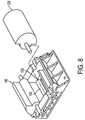
- the hopper assembly 100 includes a hopper 110 and a first tumbler 120 and a second tumbler 140 disposed at a base of the hopper 110. At the bottom of the hopper 110, there is a fill cavity 130 and a fill hole 132 ( FIG. 8 ).
- the first and second tumblers 120, 140 are driven by a drive shaft 122 and a support shaft 142, respectively.
- the first and second tumblers 120, 140 respectively have a step 121 and a step 141.
- a drive gear 124 is disposed at an end of the drive shaft 122 and a support gear 144 is disposed at an end of the support shaft 142.
- the drive gear 124 and the support gear 144 are coupled together, while only the drive gear 124 is coupled to the gear rack 150.
- An end of the gear rack 150 is attached to a first hydraulic cylinder 410 of the set of air and hydraulic cylinders 400 by a connecting member 160.
- the mold plate 200 is attached to the shuttle 210 while the shuttle 210 is slideably disposed with respect to the support frame 600.
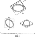
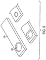
- the mold plate 200 includes a mold cavity 202 ( FIG. 2 ). Although the mold cavity 202 is shown to have a circular shape, the mold cavity can have other shapes, including oval shapes and polygonal shapes ( FIGS. 5 , 6 ). The mold plate 200 can be easily replaced depending on the shape of portioned food that is desired.
- the shuttle 210 is coupled to the hydraulic cylinder 420.
- the air knockout assembly 300a Adjacent to the hopper assembly 100, there is the air knockout assembly 300a shown in FIGS. 1 , 2 , and 3 .
- the air knockout assembly 300a includes a valve 310a communicating with a top plate 320a.
- the valve 310a may be any kind of an electrically actuated valve, including solenoid valves, for example.
- One end of the valve 310a communicates with an air cavity 324 of the top plate 320a via an air vent 326.
- Another end of the valve 310a communicates with an air line 430.
- Underneath the top plate 320a is an air knockout member 330a.
- the air knockout member 330a is a part that can be easily replaced depending on the shape of the portioned food in the mold cavity 202.
- Below the air knockout member 330a is a base plate 340.
- the base plate 340 includes clamping means 342 to firmly attach the top plate 320a to the base plate
- a separate air knockout member 330a is not required, but another means fixed to the top plate 320a or to the base plate 340 may be used to vent the compressed air onto the portioned food in the mold cavity 202.
- the air knockout member 330a in the current embodiment has a plurality of vents 332a disposed in a substantially circular shape. At the bottom of the air knockout member 330a, there is a channel 334a having substantially the same shape as the shape of the plurality of vents 332a. Inside the plurality of vents 332a, there is an inner portion 336. At the outer periphery of the air knockout member 330a, there is an outer portion 338a. The inner portion 336 has a depth less that is less than the depth of the outer portion 338a, for reasons to be explained later.
- the shape of the plurality of vents 332a of the air knockout member 330a is not limited to a substantially circular shape, but can have a substantially polygonal shape (plurality of vents 334b as shown in the air knockout member 330b in FIG. 5 ), or a substantially oval shape (plurality of vents 334c as shown in the air knockout member 330c in FIG. 6 ).
- the shape of the plurality of vents is not limited to the shapes shown but can have other shapes.
- the paper feeder 500 Adjacent to the air knockout assembly 300a, there is a paper feeder 500.
- the paper feeder 500 is of the type conventionally used in food portioning machines such as hamburger patty machines.
- the set of air and hydraulic cylinders 400 generates compressed air without requiring an outside supply of compressed air.
- the set of air and hydraulic cylinders 400 include a first hydraulic cylinder 410 which drives the gear rack 150 and a second hydraulic cylinder 420 which drives the shuttle 210.
- the set of air and hydraulic cylinders 400 also include a first air cylinder 432 and a second air cylinder 434.
- the extendable shafts of the first and second air cylinders 432, 434 are coupled to the extendable shaft of the second hydraulic cylinder 420 by a crossbar 440.
- the air cylinders 432, 434 are both connected to the air line 430.
- first and second hydraulic cylinders 410, 420 there may be a first driving means and a second driving means whose actions generate compressed air with or without a compressed air generator.
- the hopper assembly 100, shuttle 210, air knockout assembly 300a, set of air and hydraulic cylinders 400, paper feeder 500 are all disposed on a support frame 600.
- the support frame 600 is disposed on a base 620.
- the base 620 includes a drive unit 700.
- the drive unit 700 includes a programmable logic controller (PLC) 702 and a fluid pump 704.
- PLC 702 is connected to the valve 310a ( FIG. 2 ), first and second hydraulic cylinders 410, 420, and to a number of sensors, e.g., optical and/or mechanical sensors such as limit switches, disposed on the food portioning system 1000.
- the fluid pump 704 drives the first hydraulic cylinder 410 to extend its shaft to shift the gear rack 150 toward the back of the food portioning system 1000.
- the gear rack 150 is extended out to a first position, the drive gear 124 is rotated in one direction.
- the support gear 144 coupled to the drive gear 124 is rotated in an opposite direction.
- the drive gear 124 rotates the first tumbler 120 and the support gear 144 rotates the second tumbler 140.
- the movement of the gear rack 150 out to the first position serves to rotate the first and second tumblers 120, 140 inward. Consequently, the steps 121, 141 of the first and second tumblers 120, 140 push in a portion of the food material to the fill cavity 130. At this point, the food material is not yet pushed out of the fill hole 132.
- the fluid pump 704 drives the second hydraulic cylinder 420 to extend its shaft and displace the shuttle 210 toward the first fill position.
- the mold cavity 202 of the mold plate 200 is disposed underneath the fill hole 132.
- the extension of the second hydraulic cylinder shaft draws out the shafts of the first and second air cylinders 432, 434 to generate compressed air inside the first and second air cylinders 432, 434.
- the compressed air is then channeled to the air line 430.
- the gear rack 150 is further extended toward the back to a second position to further rotate the first and second tumblers 124, 144.
- the further rotation of the first and second tumblers 124, 144 pushes the food material in the fill cavity 130 out through the fill hole 132 to fill in the mold cavity 202 of the mold plate 200.
- the movement of the gear rack 150 to the second position may start as soon as a portion of the mold cavity 202 is disposed directly underneath the fill hole 132.
- the center of the mold cavity 202 need not be disposed under the fill hole 132 for the tumblers 124, 144 to start filling the mold cavity 202. Rather, the food material may be pushed out the fill hole 132 while the mold cavity 202 is moving.
- the shaft of the second hydraulic cylinder 420 shaft is retracted to displace the shuttle 210.
- the mold cavity 202 of the mold plate 200 is moved to a knockout out position underneath the air knockout assembly 300a.
- the retraction of the shaft of the second hydraulic cylinder 420 also retracts the shafts of the first and second air cylinders 432, 434 to generate compressed air.
- the air valve 300a is opened to allow compressed air generated by the air cylinders 432, 434, to flow into the top plate 320a of the air knockout assembly 300a.
- the plurality of vents of the 332a of the air knockout member 330a directs some of the compressed air to about the periphery of the portioned food in the mold cavity 202 to knock out the portioned food out of the mold plate 200.
- the channel 334a allows an even application of air pressure at about the periphery of the portioned food.
- the inner portion 336 has less depth than the outer portion 338a of the air knockout member 330a, there is an air gap between the bottom surface of the inner portion 336 of the air knockout member 330 and the top of the portioned food in the mold cavity 202.
- the air gap channels some of the compressed air toward the middle or center portion of the portioned food. The air gap thus prevents the middle or the center portion of the portioned food from sticking to the air knockout member 330a and provides additional knockout pressure at the middle of the mold cavity 202.
- the shaft of the second hydraulic cylinder 420 is extended again to move the mold cavity 202 of the mold plate 200 toward the fill position.
- the food portioning system 1000 includes a switch lever 152 attached to an end of the gear rack 150.
- a sensor 154 is disposed on the support frame 600 and aligned with the switch lever 152.
- the sensor 154 is connected to the PLC 702 so when the gear rack 160 is retracted to the front by a predetermined amount, the sensor 154 is triggered to send a signal to the PLC 702.
- PLC 702 receives the signal, the PLC 702 sends a control signal to a valve of the drive unit 700 to stop retracting and a control signal to extend the shaft of the first hydraulic cylinder 410.
- the senor 154 can be disposed anywhere on the food portioning machine 1000 as long as the sensor detects the motion of the gear rack 150 or any components attached thereto.
- a sensor 444 disposed underneath the support frame 600 and aligned with the crossbar 440.
- the crossbar 440 triggers the sensor 444 to send a signal to the PLC 702.
- the movement of the second hydraulic cylinder 420 by the predetermined distance corresponds to the positioning of the mold cavity 202 underneath the air knockout assembly 300a. Therefore, the PLC 702 sends a signal to the valve 310a to release a predetermined amount of compressed air into the top plate 320a of the air knockout assembly 300a to knock out the portioned food material out of the mold cavity 202.
- the location of the sensor 444 is not limited to the location shown in FIG. 1 , but can be disposed anywhere on the food portioning system 1000 as long as the motion of the shuttle 210 is detected.
- the release of the compressed air through the valve 310a to the air knockout assembly 300a is triggered, at least in part, electrically by the action of the sensor 444.
- the release of the compressed air is triggered mechanically.
- FIG. 7 An air knockout assembly 300b is shown in FIG. 7 .
- the top plate 320a there is a top plate 320b disposed above the base plate 340, with a cap 320c disposed above the top plate 320b.
- the air line 430 is connected to the cap 320c ( FIG. 7A ).
- the cap 320c is connected to a feed line 325 and the feed line 325 is connected to an air reservoir 311.
- the air reservoir 311 is connected to the air line 430.
- a switch 321 is pivotally mounted at a side of the base plate 340.
- the switch 321 includes a lever 321a, a lever bracket 321b, and a lever pivot pin 321c.
- One end of the lever 321a is disposed to contact the front end of the mold plate 200 and the opposite end of the lever 321a is disposed at a valve 310b.
- the valve 310b includes an air valve spool 310bb, a sleeve 310cc, a compression spring 310dd, and an end cap 310ee.
- top plate 320b includes the valve 310b to mechanically control the release of compressed air into the air cavity 324.
- the mold plate 200 pushes an end of the lever 321a to push the air valve spool 310bb into the top plate 320b to release compressed air inside the reservoir 327 into the air cavity 324 of the top plate 320b.
- a food portioning system in another embodiment, includes a hopper, a mold plate, a set of air and hydraulic drive means, and at least two air knockout assemblies.
- the mold plate is longer than the mold plate 200 and has a mold cavity disposed at both ends of the mold plate.
- Each of the two air knockout assemblies are disposed at opposite sides of the hopper.
- this embodiment is substantially similar to the food portioning system 1000. Because the mold plate has two mold cavities, a first mold cavity and a second mold cavity, the first mold cavity can be filled while the portioned food in the second mold cavity is knocked out. When the empty second mold cavity is moved to a fill position, the first mold cavity is moved out to a knockout position under the other air knockout assembly.
- portioning system of the present invention can efficiently output portioned food at a high rate without the maintenance and safety issues associated with the conventional food portioning machine.
- the use of the air knockout member allows for the precise knockout of portioned food, such as hamburger patties, to the same horizontal position below the air knockout assembly. This allows a number of hamburger patties, for example, to be vertically stacked evenly.
Landscapes
- Engineering & Computer Science (AREA)
- Life Sciences & Earth Sciences (AREA)
- Food Science & Technology (AREA)
- Wood Science & Technology (AREA)
- Zoology (AREA)
- Manufacturing & Machinery (AREA)
- Chemical & Material Sciences (AREA)
- Polymers & Plastics (AREA)
- Formation And Processing Of Food Products (AREA)
Description
- Apparatus and methods consistent with the present invention relate to food portioning machines, and more particularly, apparatuses and methods for a food portioning system for knocking out food portions out of a mold with air and using hydraulic and air cylinders to operate the food portioning system.
- In a conventional food portioning machine, there is a hopper, knockout assembly, and a mold plate disposed underneath the mold plate. In operation, flowable food material is entered into the hopper and fed into the mold plate which is driven toward the knockout assembly. The knockout assembly is a complicated mechanical system that includes a knockout cup attached at the end of a vertical knockout shaft. By the action of springs and levers, the knockout shaft is repetitively moved up and down to knock out the portioned food in the mold plate. There are, however, several problems associated with this conventional arrangement.
- First, the mechanical system of arms, shafts, springs, and knockout cups requires tight tolerances to allow the knockout plate to repetitively move through the mold plate without obstruction. The vertical and horizontal positions of the center arm and the knockout cup have to be maintained at specific tolerances to prevent unnecessary chafing between the knockout cup and the mold plate. Moreover, the mechanical system requires a high level of maintenance to keep the system in precise working order.
- Furthermore, the mechanical movement of the knockouts presents safety considerations in that an operator of the food portioning machine may injure himself by reaching inside the machine during operation.
- Additionally, the output of the machine with respect to the rate of food portions knocked out is limited in part, by the physical movement of the knockout plates. A method of molding articles according to the preamble of Claim 1 is known from
US 3,898,314 . Moreover, a food molding apparatus and a method of forming food products are known fromUS 5,618,571 . - To solve the above problems, the present invention is conceived.
- The present invention relates to a food portioning system having the features set forth in Claim1 and a method according to claim 20.
- In a preferred embodiment the system for making portioned food includes a hopper assembly comprising a tumbler; an air knockout assembly disposed adjacent to said hopper assembly, said air knockout assembly comprising an air vent member; a mold plate having a mold cavity, said mold plate slideably disposed under said hopper assembly and said air knockout assembly; a plurality of cylinders comprising: a first hydraulic cylinder coupled to said tumbler of the hopper assembly; a second hydraulic cylinder coupled to said mold plate; and an air cylinder coupled to said second hydraulic cylinder; generating compressed air for said air knockout assembly; and a control circuit controlling operations of the system.
- Other features and advantages of the present invention will be apparent from the following description taken in connection with the accompanying drawings, wherein:
-
FIG. 1 shows and embodiment of the present invention; -
FIG. 2 is a perspective view of the air knockout assembly; -
FIG. 3 is a perspective view of the top plate; -
FIG. 4 shows perspective views of the air knockout member; -
FIG. 5 shows perspective views of another embodiment of the air knockout member; -
FIG. 6 shows perspective views of yet another embodiment of the air knockout member; -
FIG. 7 is a view of another embodiment of the air knockout assembly; -
FIG. 8 shows the bottom of the hopper assembly and the tumblers; and -
FIG. 9 shows various mold plate embodiments. - A system according to one aspect of the present invention includes a hopper, a mold plate, air knockout assembly, and a set of air and hydraulic drive means. Flowable food material is put into the hopper where it is pushed into the mold cavity of the mold plate. The mold plate is driven to a knockout position by the hydraulic cylinder. Here, an air knockout assembly releases compressed air onto the mold cavity to knock out the portioned food from the mold plate.
- An exemplary embodiment will now be described with reference to
FIG. 1 showing afood portioning system 1000. Generally, thefood portioning system 1000 includes ahopper assembly 100,mold pate 200,shuttle 210,air knockout assembly 300a, a set of air andhydraulic cylinders 400, and apaper feeder 500 disposed at asupport frame 600. Thesupport frame 600 is disposed on abase 620 wherein adrive unit 700 is disposed. - The
hopper assembly 100 includes ahopper 110 and afirst tumbler 120 and asecond tumbler 140 disposed at a base of thehopper 110. At the bottom of thehopper 110, there is afill cavity 130 and a fill hole 132 (FIG. 8 ). The first andsecond tumblers drive shaft 122 and asupport shaft 142, respectively. The first andsecond tumblers step 121 and astep 141. Adrive gear 124 is disposed at an end of thedrive shaft 122 and asupport gear 144 is disposed at an end of thesupport shaft 142. Thedrive gear 124 and thesupport gear 144 are coupled together, while only thedrive gear 124 is coupled to thegear rack 150. An end of thegear rack 150 is attached to a firsthydraulic cylinder 410 of the set of air andhydraulic cylinders 400 by a connectingmember 160. - Underneath the
hopper assembly 100, there is amoveable shuttle 210. Themold plate 200 is attached to theshuttle 210 while theshuttle 210 is slideably disposed with respect to thesupport frame 600. Themold plate 200 includes a mold cavity 202 (FIG. 2 ). Although themold cavity 202 is shown to have a circular shape, the mold cavity can have other shapes, including oval shapes and polygonal shapes (FIGS. 5 ,6 ). Themold plate 200 can be easily replaced depending on the shape of portioned food that is desired. Theshuttle 210 is coupled to thehydraulic cylinder 420. - Adjacent to the
hopper assembly 100, there is theair knockout assembly 300a shown inFIGS. 1 ,2 , and3 . Theair knockout assembly 300a includes avalve 310a communicating with atop plate 320a. Thevalve 310a may be any kind of an electrically actuated valve, including solenoid valves, for example. One end of thevalve 310a communicates with anair cavity 324 of thetop plate 320a via anair vent 326. Another end of thevalve 310a communicates with anair line 430. Underneath thetop plate 320a is anair knockout member 330a. Theair knockout member 330a is a part that can be easily replaced depending on the shape of the portioned food in themold cavity 202. Below theair knockout member 330a is abase plate 340. Thebase plate 340 includes clamping means 342 to firmly attach thetop plate 320a to thebase plate 340. - Alternatively, in an embodiment not according to the invention, a separate
air knockout member 330a is not required, but another means fixed to thetop plate 320a or to thebase plate 340 may be used to vent the compressed air onto the portioned food in themold cavity 202. - As shown in
FIGS. 2 and4 , theair knockout member 330a in the current embodiment has a plurality ofvents 332a disposed in a substantially circular shape. At the bottom of theair knockout member 330a, there is achannel 334a having substantially the same shape as the shape of the plurality ofvents 332a. Inside the plurality ofvents 332a, there is aninner portion 336. At the outer periphery of theair knockout member 330a, there is anouter portion 338a. Theinner portion 336 has a depth less that is less than the depth of theouter portion 338a, for reasons to be explained later. - The shape of the plurality of
vents 332a of theair knockout member 330a is not limited to a substantially circular shape, but can have a substantially polygonal shape (plurality ofvents 334b as shown in theair knockout member 330b inFIG. 5 ), or a substantially oval shape (plurality ofvents 334c as shown in theair knockout member 330c inFIG. 6 ). The shape of the plurality of vents is not limited to the shapes shown but can have other shapes. - Adjacent to the
air knockout assembly 300a, there is apaper feeder 500. Thepaper feeder 500 is of the type conventionally used in food portioning machines such as hamburger patty machines. - There is a set of air and
hydraulic cylinders 400 disposed underneath thehopper assembly 100,shuttle 210, and theair knockout assembly 300a. The set of air andhydraulic cylinders 400 generates compressed air without requiring an outside supply of compressed air. The set of air andhydraulic cylinders 400 include a firsthydraulic cylinder 410 which drives thegear rack 150 and a secondhydraulic cylinder 420 which drives theshuttle 210. The set of air andhydraulic cylinders 400 also include afirst air cylinder 432 and asecond air cylinder 434. The extendable shafts of the first andsecond air cylinders hydraulic cylinder 420 by acrossbar 440. Theair cylinders air line 430. Alternatively, other means known in the art for driving thehopper assembly 100 and theshuttle 210 and other means known in the art for generating compressed air may be employed. For example, instead of the first and secondhydraulic cylinders - The
hopper assembly 100,shuttle 210,air knockout assembly 300a, set of air andhydraulic cylinders 400,paper feeder 500 are all disposed on asupport frame 600. Thesupport frame 600 is disposed on abase 620. Thebase 620 includes adrive unit 700. Thedrive unit 700 includes a programmable logic controller (PLC) 702 and afluid pump 704. ThePLC 702 is connected to thevalve 310a (FIG. 2 ), first and secondhydraulic cylinders food portioning system 1000. - An operation of the
food portioning system 1000 is described below. - First, flowable food material is put into the
hopper 110. Through the control of thePLC 702, thefluid pump 704 drives the firsthydraulic cylinder 410 to extend its shaft to shift thegear rack 150 toward the back of thefood portioning system 1000. As thegear rack 150 is extended out to a first position, thedrive gear 124 is rotated in one direction. Thesupport gear 144 coupled to thedrive gear 124 is rotated in an opposite direction. Thedrive gear 124 rotates thefirst tumbler 120 and thesupport gear 144 rotates thesecond tumbler 140. The movement of thegear rack 150 out to the first position serves to rotate the first andsecond tumblers steps second tumblers fill cavity 130. At this point, the food material is not yet pushed out of thefill hole 132. - Next, the
fluid pump 704 drives the secondhydraulic cylinder 420 to extend its shaft and displace theshuttle 210 toward the first fill position. When the secondhydraulic cylinder 420 is fully extended, themold cavity 202 of themold plate 200 is disposed underneath thefill hole 132. - Because the end of the shaft of the second
hydraulic cylinder 420 is connected to the shafts of the first andsecond air cylinders second air cylinders second air cylinders air line 430. - Then, the
gear rack 150 is further extended toward the back to a second position to further rotate the first andsecond tumblers second tumblers fill cavity 130 out through thefill hole 132 to fill in themold cavity 202 of themold plate 200. - It is noted that the movement of the
gear rack 150 to the second position may start as soon as a portion of themold cavity 202 is disposed directly underneath thefill hole 132. In other words, the center of themold cavity 202 need not be disposed under thefill hole 132 for thetumblers mold cavity 202. Rather, the food material may be pushed out thefill hole 132 while themold cavity 202 is moving. - After the
mold cavity 202 is filled with a portioned amount of food material, the shaft of the secondhydraulic cylinder 420 shaft is retracted to displace theshuttle 210. Themold cavity 202 of themold plate 200 is moved to a knockout out position underneath theair knockout assembly 300a. - The retraction of the shaft of the second
hydraulic cylinder 420 also retracts the shafts of the first andsecond air cylinders - The
air valve 300a is opened to allow compressed air generated by theair cylinders top plate 320a of theair knockout assembly 300a. The plurality of vents of the 332a of theair knockout member 330a directs some of the compressed air to about the periphery of the portioned food in themold cavity 202 to knock out the portioned food out of themold plate 200. Thechannel 334a allows an even application of air pressure at about the periphery of the portioned food. Because theinner portion 336 has less depth than theouter portion 338a of theair knockout member 330a, there is an air gap between the bottom surface of theinner portion 336 of the air knockout member 330 and the top of the portioned food in themold cavity 202. The air gap channels some of the compressed air toward the middle or center portion of the portioned food. The air gap thus prevents the middle or the center portion of the portioned food from sticking to theair knockout member 330a and provides additional knockout pressure at the middle of themold cavity 202. - When the shaft of the second
hydraulic cylinder 420 is retracted, thegear rack 150 is retracted as well, to rotate thesteps second tumblers - After the portioned food is knocked out of the
mold plate 200, the shaft of the secondhydraulic cylinder 420 is extended again to move themold cavity 202 of themold plate 200 toward the fill position. - To detect the movement of the various components of the
food portioning system 1000, including the motion of thegear rack 150 and theshuttle 210, there is a plurality of sensors. - For example, the
food portioning system 1000 includes aswitch lever 152 attached to an end of thegear rack 150. A sensor 154 is disposed on thesupport frame 600 and aligned with theswitch lever 152. The sensor 154 is connected to thePLC 702 so when thegear rack 160 is retracted to the front by a predetermined amount, the sensor 154 is triggered to send a signal to thePLC 702. WhenPLC 702 receives the signal, thePLC 702 sends a control signal to a valve of thedrive unit 700 to stop retracting and a control signal to extend the shaft of the firsthydraulic cylinder 410. - It noted that the sensor 154 can be disposed anywhere on the
food portioning machine 1000 as long as the sensor detects the motion of thegear rack 150 or any components attached thereto. - As another example of a sensor used to detect a motion of a component of the
food portioning system 1000, there is asensor 444 disposed underneath thesupport frame 600 and aligned with thecrossbar 440. When the shaft of the secondhydraulic cylinder 420 is retracted to a predetermined distance, thecrossbar 440 triggers thesensor 444 to send a signal to thePLC 702. The movement of the secondhydraulic cylinder 420 by the predetermined distance corresponds to the positioning of themold cavity 202 underneath theair knockout assembly 300a. Therefore, thePLC 702 sends a signal to thevalve 310a to release a predetermined amount of compressed air into thetop plate 320a of theair knockout assembly 300a to knock out the portioned food material out of themold cavity 202. - The location of the
sensor 444 is not limited to the location shown inFIG. 1 , but can be disposed anywhere on thefood portioning system 1000 as long as the motion of theshuttle 210 is detected. - In the above embodiment of the
air knockout assembly 300a, the release of the compressed air through thevalve 310a to theair knockout assembly 300a is triggered, at least in part, electrically by the action of thesensor 444. Alternatively, the release of the compressed air is triggered mechanically. - An air knockout assembly 300b is shown in
FIG. 7 . Instead of thetop plate 320a, there is atop plate 320b disposed above thebase plate 340, with acap 320c disposed above thetop plate 320b. Theair line 430 is connected to thecap 320c (FIG. 7A ). - Alternatively, the
cap 320c is connected to a feed line 325 and the feed line 325 is connected to an air reservoir 311. In this alternative embodiment, the air reservoir 311 is connected to theair line 430. - A
switch 321 is pivotally mounted at a side of thebase plate 340. Theswitch 321 includes alever 321a, alever bracket 321b, and alever pivot pin 321c. One end of thelever 321a is disposed to contact the front end of themold plate 200 and the opposite end of thelever 321a is disposed at avalve 310b. Thevalve 310b includes an air valve spool 310bb, a sleeve 310cc, a compression spring 310dd, and an end cap 310ee. Unlike thetop plate 320a,top plate 320b includes thevalve 310b to mechanically control the release of compressed air into theair cavity 324. - Here, when the
mold cavity 202 is positioned under the air knockout assembly 300b, themold plate 200 pushes an end of thelever 321a to push the air valve spool 310bb into thetop plate 320b to release compressed air inside the reservoir 327 into theair cavity 324 of thetop plate 320b. - In another embodiment of the present invention, a food portioning system includes a hopper, a mold plate, a set of air and hydraulic drive means, and at least two air knockout assemblies. In this embodiment, the mold plate is longer than the
mold plate 200 and has a mold cavity disposed at both ends of the mold plate. Each of the two air knockout assemblies are disposed at opposite sides of the hopper. In all other respects, this embodiment is substantially similar to thefood portioning system 1000. Because the mold plate has two mold cavities, a first mold cavity and a second mold cavity, the first mold cavity can be filled while the portioned food in the second mold cavity is knocked out. When the empty second mold cavity is moved to a fill position, the first mold cavity is moved out to a knockout position under the other air knockout assembly. - Through the use of air knockouts and a set of air and hydraulic cylinders, food portioning system of the present invention can efficiently output portioned food at a high rate without the maintenance and safety issues associated with the conventional food portioning machine. As an added benefit, the use of the air knockout member allows for the precise knockout of portioned food, such as hamburger patties, to the same horizontal position below the air knockout assembly. This allows a number of hamburger patties, for example, to be vertically stacked evenly.
- While the present invention has been particularly shown and described with reference to exemplary embodiments thereof, it will be understood by those of ordinary skill in the art that various changes in form and details may be made therein without departing from the spirit and scope of the present invention as defined by the appended claims.
Claims (24)
- A food portioning system comprising:means (100) for receiving and ejecting food into a mold cavity (202) of a mold plate (200);means (300a) for pushing out portioned food using pneumatic pressure;a plurality of driving means (210, 150, 160, 400, 440) comprising:first means (410) for driving said means (100) for receiving and ejecting food;second means (210, 420) for driving said mold plate (200);third means (432, 434) for generating compressed air for said means (330a) for pushing out portioned food; andmeans (700) for controlling operations of said system,characterized in that said third means (432, 434) are connected to said second means (210, 420) by a connecting means (440) for connecting said second (420) and third (432, 434) means and for causing said second means (210, 420) to drive said mold plate (200) while said third means (432, 434) generates the compressed air used as pneumatic pressure for pushing out said portioned food.
- The system of Claim 1, characterized in that said driving means (124, 144, 150, 160, 210, 400, 440) are used for moving said mold plate (200) to at least one of two positions; and
wherein said driving means (124, 144, 150, 160, 210, 400, 440) drives said means (432, 434) for generating compressed air to generate compressed air used to push the food out of said mold cavity (202) of said mold plate (200). - The system of Claim 2, characterized in that the two positions are a fill position for filling in unportioned food in said mold cavity (202) and a pushing position for pushing out portioned food in said mold cavity (202).
- The system of claim 3, characterized in that said means (432, 434) for generating compressed air generates compressed air at least when said driving means (124, 144, 150, 160, 210, 400, 440) drives said mold plate (202) to said pushing position.
- The system of any of the previous claims, characterized in that:said means (100) for receiving and ejecting food include a hopper assembly (100) comprising a tumbler (120, 140);said means (300a) for pushing out portioned food include an air knockout assembly (300a) disposed adjacent to said hopper assembly (100), and said air knockout assembly (300a) comprises an air vent member (332a);said mold plate (200) has a mold cavity (202), and is slideably (210) disposed under said hopper assembly (100) and said air knockout assembly (300a); andsaid plurality of driving means (210, 150, 160, 400, 440) comprises a plurality of cylinders (400) wherein:said first means includes an hydraulic cylinder (410) coupled (150) to said tumbler (120) of the hopper assembly (100);said second means includes an hydraulic cylinder (420) coupled (210) to said mold plate (200); andsaid third means includes an air cylinder (432) connected (440) to said second hydraulic cylinder (420), said air cylinder (432) generating said compressed air for said air knockout assembly (300a); andsaid means (700) for controlling operations of said system comprises a control circuit (702).
- The system of Claim 5, characterized in that said control circuit (702) drives said second cylinder (420) to reciprocatively drive said mold cavity (202) of the mold plate (200) to one of said fill position below said hopper assembly (100) and said knockout position below said air knockout assembly (300a).
- The system of claim 6, characterized in that when said mold cavity (202) is driven to said fill position, said first hydraulic cylinder (410) drives said tumbler (120) to push food out of said hopper assembly (100) into said mold cavity (202).
- The system of claim 7, characterized in that said air cylinder (432) generates compressed air, and the compressed air is channeled (334a) to the air knockout assembly (300a) to knock out said portioned food out of said mold cavity (202) disposed to said knockout position.
- The system of claim 8, characterized in that said control circuit (702) drives said second cylinder (420) to drive said mold cavity (202) of the mold plate (200) to one of said fill position and said knockout position,
said first hydraulic cylinder (410) drives said tumbler (120) to push food material out of said hopper (100) into said mold cavity (202) of said mold plate (200) at said fill position,
said second hydraulic cylinder (420) drives said mold plate (200) to the knockout position,
said air cylinder (432) generates compressed air, and
said compressed air is channeled (334a) to said air knockout assembly (300a) to knock out said portioned food out of said mold cavity (200). - The system of claim 9, characterized in that movements of the first (410) and the second (420) hydraulic cylinders are synchronized such that said first hydraulic cylinder (410) drives said tumbler (120) to push food material out of said hopper (100) when said second hydraulic cylinder (420) moves said mold plate (200) to said fill position.
- The system of any of the previous claims, characterized in that it includes a plate (320a) comprising:an upper surface and a lower surface;a plurality of vents (332a) disposed between said upper surface and said lower surface, said plurality of vents (332a) arranged in a pattern; anda channel (334a) disposed underneath said plurality of vents (332a), said channel (334a) having a shape that is substantially identical to said pattern;wherein said lower surface comprises a first area (336) inside said pattern and a second area (338a) outside said pattern and said first area (336) is not level with said second area (338a).
- The system of claim 11, characterized in that a depth of said first area (336) with respect to the upper surface is less than a depth of said second area (338a) with respect to the upper surface.
- The system of claim 11 or 12, characterized in that it further comprises an air space bounded by said channel (334a).
- The system of any of claims 11 to 13, characterized in that said pattern is a closed shape substantially corresponding to said mold cavity (202) in said mold plate (200).
- The system of claim 14, characterized in that it further comprises an air space bounded by said channel (334a) disposed underneath said first area (336), wherein a depth of said first area (336) with respect to the upper surface is less than a depth of said second area (338a) with respect to the upper surface and said channel (334a) communicates said plurality of vents (332a) with said air space.
- The system of claim 15, characterized in that said plurality of vents (332a) diffuse compressed air toward said mold cavity (202) to have a first air pressure above the food in said mold cavity (202) that is higher than a second air pressure below the food to eject food from said mold cavity (202).
- The system of any of the claims 5 to 16, characterized in that said hydraulic cylinder (420) comprises a first shaft and said air cylinder (432) comprises a second shaft and a distal end of said first shaft is connected to a distal end of said second shaft.
- The system of claim 17, characterized in that a first shaft of said hydraulic cylinder (420) moves in one direction to drive said mold plate (200) to the fill position and to simultaneously move a second shaft of said air cylinder (432), and unportioned food is filled in said mold cavity (202) of said mold plate (200).
- The system of claim 18, characterized in that the first shaft of said hydraulic cylinder (420) moves in another direction to drive said mold plate (200) to the knock out position and to simultaneously move the second shaft of said air cylinder (432) to generate said compressed air.
- A method of forming portioned food, said method comprising:pushing (300a) portioned food out of a mold cavity (202) of a mold plate (200) using only air, said pushing (300a) comprising:directing said air out of a plurality of vents (332a) of a member (330a) disposed above said mold plate (200);channeling (334a) said air into an air cavity (324) disposed above said mold plate (200), the air cavity (324) bounded by a recessed area of a lower surface of the member (330a) and the portioned food; andincreasing air pressure in said air cavity (324),wherein the increase in the air pressure in said air cavity (324) pushes the portioned food out of said mold cavity (202) of said mold plate (200), the method being characterized in that it comprises:first driving a hydraulic cylinder (410) to move said mold plate (200) in one direction;filling (100) in unportioned food in said mold cavity (202) of said mold plate (200);second driving said hydraulic cylinder (410) to move said mold plate (200) in another direction and generating (432) compressed air;channeling (334a) said compressed air toward said mold cavity (202); andpushing out portioned food in said mold cavity (202)..
- The method of claim 20, characterized in that it further comprises:filling in unportioned food into the mold cavity (202) of said mold plate (200) to have portioned food.
- The method of claim 21, characterized in that the operation of pushing (300a) portioned food out of the mold cavity (202) and the operation of filling in (120) unportioned food into the mold cavity (202) are alternatingly performed.
- The method of claim 22, characterized in that it further comprises reciprocatively moving said mold plate (200) to at least one of a fill position for the operation of filling in the unportioned food and a pushing out position for pushing the portioned food out of the mold cavity (202).
- The method of claim 20, characterized in that the operation of second driving comprises:driving a shaft of said hydraulic cylinder to move said mold plate and to drive an air cylinder to generate said compressed air.
Priority Applications (1)
| Application Number | Priority Date | Filing Date | Title |
|---|---|---|---|
| EP10195978.1A EP2289339B1 (en) | 2004-07-15 | 2005-07-15 | Food portioning system |
Applications Claiming Priority (2)
| Application Number | Priority Date | Filing Date | Title |
|---|---|---|---|
| US58793304P | 2004-07-15 | 2004-07-15 | |
| PCT/US2005/025311 WO2006020139A1 (en) | 2004-07-15 | 2005-07-15 | Food portioning system |
Related Child Applications (2)
| Application Number | Title | Priority Date | Filing Date |
|---|---|---|---|
| EP10195978.1A Division EP2289339B1 (en) | 2004-07-15 | 2005-07-15 | Food portioning system |
| EP10195978.1A Division-Into EP2289339B1 (en) | 2004-07-15 | 2005-07-15 | Food portioning system |
Publications (3)
| Publication Number | Publication Date |
|---|---|
| EP1773165A1 EP1773165A1 (en) | 2007-04-18 |
| EP1773165A4 EP1773165A4 (en) | 2008-10-22 |
| EP1773165B1 true EP1773165B1 (en) | 2016-04-13 |
Family
ID=35907721
Family Applications (2)
| Application Number | Title | Priority Date | Filing Date |
|---|---|---|---|
| EP10195978.1A Active EP2289339B1 (en) | 2004-07-15 | 2005-07-15 | Food portioning system |
| EP05775365.9A Active EP1773165B1 (en) | 2004-07-15 | 2005-07-15 | Food portioning system |
Family Applications Before (1)
| Application Number | Title | Priority Date | Filing Date |
|---|---|---|---|
| EP10195978.1A Active EP2289339B1 (en) | 2004-07-15 | 2005-07-15 | Food portioning system |
Country Status (5)
| Country | Link |
|---|---|
| US (3) | US7824172B2 (en) |
| EP (2) | EP2289339B1 (en) |
| AU (1) | AU2005274847B2 (en) |
| CA (1) | CA2573808C (en) |
| WO (1) | WO2006020139A1 (en) |
Families Citing this family (22)
| Publication number | Priority date | Publication date | Assignee | Title |
|---|---|---|---|---|
| WO2008091949A2 (en) * | 2007-01-23 | 2008-07-31 | Formax, Inc. | Food patty molding machine |
| ES2484843T3 (en) | 2008-07-04 | 2014-08-12 | Cfs Bakel B.V. | Apparatus and process of formation of food products |
| JP5347582B2 (en) * | 2009-03-09 | 2013-11-20 | ソニー株式会社 | 3D modeling equipment |
| CN102892296B (en) | 2010-04-23 | 2016-05-11 | Cfs巴克尔有限公司 | 3D food shaping apparatus and process |
| DE102010019636A1 (en) * | 2010-05-06 | 2011-11-10 | Multivac Sepp Haggenmüller Gmbh & Co. Kg | Packaging machine and method with compressed air generation |
| EP2449893B1 (en) | 2010-11-04 | 2016-08-17 | GEA Food Solutions Bakel B.V. | Mass distribution device and molding device |
| ES2810024T3 (en) | 2010-11-23 | 2021-03-08 | Gea Food Solutions Bakel Bv | Apparatus and method for the production of a product with a separator sheet |
| PL2468104T3 (en) | 2010-12-23 | 2019-02-28 | Gea Food Solutions Bakel B.V. | Cleaning method for a mould drum |
| ES2541841T3 (en) | 2011-01-25 | 2015-07-27 | Gea Food Solutions Bakel B.V. | Food production chain |
| US9730467B2 (en) | 2011-02-10 | 2017-08-15 | Gea Food Solutions Bakel B.V. | Food forming drum |
| CA2841854C (en) | 2011-07-25 | 2017-08-22 | Gea Food Solutions Bakel B.V. | Food forming apparatus with a food feed member |
| WO2013082312A1 (en) * | 2011-11-29 | 2013-06-06 | Formax, Inc. | Knockout plunger for patty-forming machine |
| RU2656384C1 (en) | 2012-01-20 | 2018-06-05 | Геа Фуд Сольюшнс Бакел Б.В. | System for feeding mass |
| ES2892334T3 (en) | 2013-02-01 | 2022-02-03 | Gea Food Solutions Bakel Bv | Food Forming Drum |
| CN110150361B (en) * | 2013-04-03 | 2022-06-24 | Gea 食品策划巴克尔公司 | Box cleaning unit |
| JP6393313B2 (en) | 2013-05-03 | 2018-09-19 | ジーイーエイ・フード・ソリューションズ・バーケル・ベスローテン・フェンノートシャップ | Sealing member for food forming drum |
| US9510602B2 (en) * | 2013-05-07 | 2016-12-06 | Cardinal Meat Specialists Limited | System and methods for continuous production of proteinaceous patties dressed with food grade particulate |
| DE102014118500A1 (en) * | 2014-12-12 | 2016-06-16 | Alpma Alpenland Maschinenbau Gmbh | Device for deforming and / or moving a food product and corresponding method |
| RU2718000C2 (en) | 2015-03-13 | 2020-03-27 | Геа Фуд Сольюшнс Бакел Б.В. | Method for cleaning and storage of molding drum |
| NL2018036B1 (en) * | 2016-12-21 | 2018-06-28 | Marel Townsend Further Proc Bv | Installations and methods for moulding food products with a pressurized air food product ejection system from a mould drum |
| CN112663421B (en) * | 2020-12-09 | 2022-06-14 | 新兴县英浩建筑陶瓷有限公司 | Ceramic product and production equipment and production method thereof |
| CN114701041B (en) * | 2022-03-29 | 2024-05-17 | 瑞泰科技股份有限公司湘潭分公司 | Method and equipment for recycling modified water glass quartz sand |
Citations (1)
| Publication number | Priority date | Publication date | Assignee | Title |
|---|---|---|---|---|
| US4987643A (en) * | 1989-08-10 | 1991-01-29 | Marlen Research Corporation | Slide plate patty forming apparatus |
Family Cites Families (35)
| Publication number | Priority date | Publication date | Assignee | Title |
|---|---|---|---|---|
| US398314A (en) * | 1889-02-19 | Herbert l | ||
| US900573A (en) * | 1908-06-26 | 1908-10-06 | Charles E Mccarren | Ice-cream spoon. |
| US1142354A (en) * | 1914-03-11 | 1915-06-08 | Robert Malcom | Ice-cream spoon. |
| US1485677A (en) * | 1923-02-06 | 1924-03-04 | George E Holmes | Ice-cream disher |
| US1508915A (en) * | 1923-10-02 | 1924-09-16 | Earl E Bidwell | Ice-cream scoop |
| US1587538A (en) * | 1924-04-18 | 1926-06-08 | George E Holmes | Measuring ice-cream disher |
| US1903791A (en) * | 1932-04-02 | 1933-04-18 | Myers Louis | Ice cream ladle |
| US2041200A (en) * | 1934-02-16 | 1936-05-19 | Myers Mfg Company | Disher |
| US2135815A (en) * | 1934-02-26 | 1938-11-08 | Meyer Hecht Company | Surfacing plate |
| US2315815A (en) * | 1941-02-15 | 1943-04-06 | American Swiss Co | Vehicle door latch |
| US2454735A (en) * | 1946-07-20 | 1948-11-23 | Deutsch | Ice-cream scoop |
| US3177524A (en) * | 1963-03-25 | 1965-04-13 | Claude M Snyder | Meat molding machine |
| US3787163A (en) * | 1971-12-29 | 1974-01-22 | N Denison | Powered ice cream dipper |
| US3898314A (en) | 1972-02-10 | 1975-08-05 | Teledyne Mid America Corp | Method of molding rubber articles |
| JPS5345237B2 (en) * | 1974-08-05 | 1978-12-05 | ||
| US4076482A (en) * | 1976-03-04 | 1978-02-28 | Whetstone Henry M | Charge forming and depositing machine |
| USRE31857E (en) * | 1979-03-29 | 1985-04-02 | Holly Systems, Inc. | Method for making food patty |
| US4317259A (en) * | 1979-10-22 | 1982-03-02 | Hollymatic Corporation | Molding apparatus |
| JPS5917453Y2 (en) * | 1980-06-02 | 1984-05-22 | 相生精機株式会社 | Pneumatic/hydraulic drive device for slide knockout device of press machine |
| US4578027A (en) * | 1984-05-29 | 1986-03-25 | Nabisco Brands, Inc. | Die having air passages |
| US5037350A (en) * | 1984-12-14 | 1991-08-06 | Hardee's Food Systems, Inc. | Method and apparatus for forming meat patties having a closer-to-handformed appearance and texture |
| JPS63164835A (en) * | 1986-12-26 | 1988-07-08 | レオン自動機株式会社 | Quantitative feeder |
| US4981430A (en) * | 1989-01-23 | 1991-01-01 | Zimmerman Jr Joseph E | Pneumatically operated mold ejection apparatus |
| US4996743A (en) * | 1990-01-29 | 1991-03-05 | Formax, Inc. | Mold plate drive linkage |
| US5145454A (en) * | 1990-07-26 | 1992-09-08 | Nutec Manufacturing, Inc. | Patty machine |
| ES2112679B1 (en) * | 1994-01-24 | 1998-11-01 | Gaser Ind | IMPROVEMENTS IN A HAMBURGER MAKING MACHINE. |
| US5445512A (en) * | 1994-01-27 | 1995-08-29 | Marlen Research Corporation | Segmented piston face plate assembly for patty forming apparatus |
| GB9506940D0 (en) * | 1995-04-04 | 1995-05-24 | British Ceramic Res Ltd | Ware forming method and apparatus |
| US5795610A (en) * | 1995-07-10 | 1998-08-18 | Stein, Inc. | Food molding apparatus and method of forming food products |
| US5618571A (en) | 1995-07-10 | 1997-04-08 | Stein, Inc. | Food molding apparatus and method of forming food products |
| JP3436289B2 (en) * | 1995-10-30 | 2003-08-11 | 日本電信電話株式会社 | Shim feature point position detection method |
| US5730650A (en) * | 1996-08-29 | 1998-03-24 | Progressive Technology Of Wisconsin, Inc. | Food patty molding machine |
| US6156358A (en) * | 1998-03-24 | 2000-12-05 | Progressive Technology Of Wisconsin, Inc. | Control of food patty molding machine |
| US6428303B2 (en) * | 1998-06-05 | 2002-08-06 | Formax, Inc. | Food patty molding machine |
| US6572360B1 (en) * | 2000-04-28 | 2003-06-03 | Golden State Foods Corporation | Food patty molding apparatus |
-
2005
- 2005-07-15 AU AU2005274847A patent/AU2005274847B2/en active Active
- 2005-07-15 WO PCT/US2005/025311 patent/WO2006020139A1/en not_active Application Discontinuation
- 2005-07-15 US US11/181,806 patent/US7824172B2/en active Active
- 2005-07-15 US US11/181,873 patent/US7824599B2/en active Active
- 2005-07-15 US US11/181,825 patent/US7655173B2/en active Active
- 2005-07-15 EP EP10195978.1A patent/EP2289339B1/en active Active
- 2005-07-15 CA CA2573808A patent/CA2573808C/en active Active
- 2005-07-15 EP EP05775365.9A patent/EP1773165B1/en active Active
Patent Citations (1)
| Publication number | Priority date | Publication date | Assignee | Title |
|---|---|---|---|---|
| US4987643A (en) * | 1989-08-10 | 1991-01-29 | Marlen Research Corporation | Slide plate patty forming apparatus |
Also Published As
| Publication number | Publication date |
|---|---|
| CA2573808C (en) | 2013-04-09 |
| EP2289339B1 (en) | 2016-04-20 |
| US20060013916A1 (en) | 2006-01-19 |
| EP2289339A3 (en) | 2013-05-01 |
| US7824172B2 (en) | 2010-11-02 |
| EP2289339A2 (en) | 2011-03-02 |
| EP1773165A4 (en) | 2008-10-22 |
| EP1773165A1 (en) | 2007-04-18 |
| CA2573808A1 (en) | 2006-02-23 |
| US20060013917A1 (en) | 2006-01-19 |
| AU2005274847A1 (en) | 2006-02-23 |
| WO2006020139A1 (en) | 2006-02-23 |
| US20060013915A1 (en) | 2006-01-19 |
| US7824599B2 (en) | 2010-11-02 |
| US7655173B2 (en) | 2010-02-02 |
| AU2005274847B2 (en) | 2011-03-10 |
Similar Documents
| Publication | Publication Date | Title |
|---|---|---|
| EP1773165B1 (en) | Food portioning system | |
| US7416753B2 (en) | Breather system for a reciprocating mold plate patty-forming machine | |
| US7255554B2 (en) | Cooling air system for a patty-forming apparatus | |
| US4987643A (en) | Slide plate patty forming apparatus | |
| JPH066026B2 (en) | Food pattern forming machine | |
| EP0311056B1 (en) | Paper interleaver for food patty | |
| US7901200B2 (en) | Molding apparatus | |
| JPS58500942A (en) | Modular rotary casting machine | |
| US20100209575A1 (en) | Linear Actuator Assisted Knockout Mechanism for a Food Patty Forming Machine | |
| CA2028780C (en) | Rotary type injection orientation blow molding machine | |
| EP1222979B1 (en) | Compressing method for casting sand and device therefor | |
| US7594532B2 (en) | Method of operation for an apparatus for making an upper and a lower mold and the apparatus therefor | |
| US3939899A (en) | Shell molding machine in which blown core can be ejected outside vise assembly | |
| US6156358A (en) | Control of food patty molding machine | |
| US1974214A (en) | Machine for manufacturing bushings | |
| SU655538A1 (en) | Apparatus for moulding articles from powder mass | |
| JP3563556B2 (en) | Molded product unloading device in powder molding machine | |
| SU388828A1 (en) | AUTOMATIC MACHINE FOR SAFE STANDING FORMING | |
| JPH0999337A (en) | Press | |
| JP2014108442A (en) | Material powder supply method, material powder supply device, and powder molding apparatus | |
| GB2246537A (en) | Removing injection moulded articles from between opened moulds |
Legal Events
| Date | Code | Title | Description |
|---|---|---|---|
| PUAI | Public reference made under article 153(3) epc to a published international application that has entered the european phase |
Free format text: ORIGINAL CODE: 0009012 |
|
| 17P | Request for examination filed |
Effective date: 20070109 |
|
| AK | Designated contracting states |
Kind code of ref document: A1 Designated state(s): AT BE BG CH CY CZ DE DK EE ES FI FR GB GR HU IE IS IT LI LT LU LV MC NL PL PT RO SE SI SK TR |
|
| DAX | Request for extension of the european patent (deleted) | ||
| A4 | Supplementary search report drawn up and despatched |
Effective date: 20080918 |
|
| 17Q | First examination report despatched |
Effective date: 20081222 |
|
| GRAP | Despatch of communication of intention to grant a patent |
Free format text: ORIGINAL CODE: EPIDOSNIGR1 |
|
| RIC1 | Information provided on ipc code assigned before grant |
Ipc: A22C 7/00 20060101ALI20150831BHEP Ipc: A47J 43/20 20060101AFI20150831BHEP Ipc: A23P 1/10 20060101ALI20150831BHEP |
|
| INTG | Intention to grant announced |
Effective date: 20150924 |
|
| GRAS | Grant fee paid |
Free format text: ORIGINAL CODE: EPIDOSNIGR3 |
|
| GRAA | (expected) grant |
Free format text: ORIGINAL CODE: 0009210 |
|
| RIC1 | Information provided on ipc code assigned before grant |
Ipc: A22C 7/00 20060101ALI20160301BHEP Ipc: A23P 10/00 20160101ALI20160301BHEP Ipc: A47J 43/20 20060101AFI20160301BHEP |
|
| AK | Designated contracting states |
Kind code of ref document: B1 Designated state(s): AT BE BG CH CY CZ DE DK EE ES FI FR GB GR HU IE IS IT LI LT LU LV MC NL PL PT RO SE SI SK TR |
|
| REG | Reference to a national code |
Ref country code: GB Ref legal event code: FG4D |
|
| REG | Reference to a national code |
Ref country code: AT Ref legal event code: REF Ref document number: 789138 Country of ref document: AT Kind code of ref document: T Effective date: 20160415 Ref country code: CH Ref legal event code: NV Representative=s name: ISLER AND PEDRAZZINI AG, CH Ref country code: CH Ref legal event code: EP |
|
| REG | Reference to a national code |
Ref country code: IE Ref legal event code: FG4D |
|
| REG | Reference to a national code |
Ref country code: DE Ref legal event code: R096 Ref document number: 602005048993 Country of ref document: DE |
|
| REG | Reference to a national code |
Ref country code: FR Ref legal event code: PLFP Year of fee payment: 12 |
|
| REG | Reference to a national code |
Ref country code: LT Ref legal event code: MG4D |
|
| REG | Reference to a national code |
Ref country code: AT Ref legal event code: MK05 Ref document number: 789138 Country of ref document: AT Kind code of ref document: T Effective date: 20160413 |
|
| REG | Reference to a national code |
Ref country code: NL Ref legal event code: MP Effective date: 20160413 |
|
| PG25 | Lapsed in a contracting state [announced via postgrant information from national office to epo] |
Ref country code: LT Free format text: LAPSE BECAUSE OF FAILURE TO SUBMIT A TRANSLATION OF THE DESCRIPTION OR TO PAY THE FEE WITHIN THE PRESCRIBED TIME-LIMIT Effective date: 20160413 Ref country code: NL Free format text: LAPSE BECAUSE OF FAILURE TO SUBMIT A TRANSLATION OF THE DESCRIPTION OR TO PAY THE FEE WITHIN THE PRESCRIBED TIME-LIMIT Effective date: 20160413 Ref country code: PL Free format text: LAPSE BECAUSE OF FAILURE TO SUBMIT A TRANSLATION OF THE DESCRIPTION OR TO PAY THE FEE WITHIN THE PRESCRIBED TIME-LIMIT Effective date: 20160413 Ref country code: FI Free format text: LAPSE BECAUSE OF FAILURE TO SUBMIT A TRANSLATION OF THE DESCRIPTION OR TO PAY THE FEE WITHIN THE PRESCRIBED TIME-LIMIT Effective date: 20160413 |
|
| PG25 | Lapsed in a contracting state [announced via postgrant information from national office to epo] |
Ref country code: PT Free format text: LAPSE BECAUSE OF FAILURE TO SUBMIT A TRANSLATION OF THE DESCRIPTION OR TO PAY THE FEE WITHIN THE PRESCRIBED TIME-LIMIT Effective date: 20160816 Ref country code: GR Free format text: LAPSE BECAUSE OF FAILURE TO SUBMIT A TRANSLATION OF THE DESCRIPTION OR TO PAY THE FEE WITHIN THE PRESCRIBED TIME-LIMIT Effective date: 20160714 Ref country code: ES Free format text: LAPSE BECAUSE OF FAILURE TO SUBMIT A TRANSLATION OF THE DESCRIPTION OR TO PAY THE FEE WITHIN THE PRESCRIBED TIME-LIMIT Effective date: 20160413 Ref country code: AT Free format text: LAPSE BECAUSE OF FAILURE TO SUBMIT A TRANSLATION OF THE DESCRIPTION OR TO PAY THE FEE WITHIN THE PRESCRIBED TIME-LIMIT Effective date: 20160413 Ref country code: LV Free format text: LAPSE BECAUSE OF FAILURE TO SUBMIT A TRANSLATION OF THE DESCRIPTION OR TO PAY THE FEE WITHIN THE PRESCRIBED TIME-LIMIT Effective date: 20160413 Ref country code: SE Free format text: LAPSE BECAUSE OF FAILURE TO SUBMIT A TRANSLATION OF THE DESCRIPTION OR TO PAY THE FEE WITHIN THE PRESCRIBED TIME-LIMIT Effective date: 20160413 |
|
| PG25 | Lapsed in a contracting state [announced via postgrant information from national office to epo] |
Ref country code: BE Free format text: LAPSE BECAUSE OF FAILURE TO SUBMIT A TRANSLATION OF THE DESCRIPTION OR TO PAY THE FEE WITHIN THE PRESCRIBED TIME-LIMIT Effective date: 20160413 Ref country code: IT Free format text: LAPSE BECAUSE OF FAILURE TO SUBMIT A TRANSLATION OF THE DESCRIPTION OR TO PAY THE FEE WITHIN THE PRESCRIBED TIME-LIMIT Effective date: 20160413 |
|
| REG | Reference to a national code |
Ref country code: DE Ref legal event code: R097 Ref document number: 602005048993 Country of ref document: DE |
|
| PG25 | Lapsed in a contracting state [announced via postgrant information from national office to epo] |
Ref country code: CZ Free format text: LAPSE BECAUSE OF FAILURE TO SUBMIT A TRANSLATION OF THE DESCRIPTION OR TO PAY THE FEE WITHIN THE PRESCRIBED TIME-LIMIT Effective date: 20160413 Ref country code: RO Free format text: LAPSE BECAUSE OF FAILURE TO SUBMIT A TRANSLATION OF THE DESCRIPTION OR TO PAY THE FEE WITHIN THE PRESCRIBED TIME-LIMIT Effective date: 20160413 Ref country code: SK Free format text: LAPSE BECAUSE OF FAILURE TO SUBMIT A TRANSLATION OF THE DESCRIPTION OR TO PAY THE FEE WITHIN THE PRESCRIBED TIME-LIMIT Effective date: 20160413 Ref country code: EE Free format text: LAPSE BECAUSE OF FAILURE TO SUBMIT A TRANSLATION OF THE DESCRIPTION OR TO PAY THE FEE WITHIN THE PRESCRIBED TIME-LIMIT Effective date: 20160413 Ref country code: DK Free format text: LAPSE BECAUSE OF FAILURE TO SUBMIT A TRANSLATION OF THE DESCRIPTION OR TO PAY THE FEE WITHIN THE PRESCRIBED TIME-LIMIT Effective date: 20160413 |
|
| PLBE | No opposition filed within time limit |
Free format text: ORIGINAL CODE: 0009261 |
|
| STAA | Information on the status of an ep patent application or granted ep patent |
Free format text: STATUS: NO OPPOSITION FILED WITHIN TIME LIMIT |
|
| 26N | No opposition filed |
Effective date: 20170116 |
|
| PG25 | Lapsed in a contracting state [announced via postgrant information from national office to epo] |
Ref country code: MC Free format text: LAPSE BECAUSE OF FAILURE TO SUBMIT A TRANSLATION OF THE DESCRIPTION OR TO PAY THE FEE WITHIN THE PRESCRIBED TIME-LIMIT Effective date: 20160413 |
|
| REG | Reference to a national code |
Ref country code: IE Ref legal event code: MM4A |
|
| PG25 | Lapsed in a contracting state [announced via postgrant information from national office to epo] |
Ref country code: SI Free format text: LAPSE BECAUSE OF FAILURE TO SUBMIT A TRANSLATION OF THE DESCRIPTION OR TO PAY THE FEE WITHIN THE PRESCRIBED TIME-LIMIT Effective date: 20160413 |
|
| REG | Reference to a national code |
Ref country code: FR Ref legal event code: PLFP Year of fee payment: 13 |
|
| PG25 | Lapsed in a contracting state [announced via postgrant information from national office to epo] |
Ref country code: IE Free format text: LAPSE BECAUSE OF NON-PAYMENT OF DUE FEES Effective date: 20160715 |
|
| PG25 | Lapsed in a contracting state [announced via postgrant information from national office to epo] |
Ref country code: LU Free format text: LAPSE BECAUSE OF NON-PAYMENT OF DUE FEES Effective date: 20160715 |
|
| PG25 | Lapsed in a contracting state [announced via postgrant information from national office to epo] |
Ref country code: HU Free format text: LAPSE BECAUSE OF FAILURE TO SUBMIT A TRANSLATION OF THE DESCRIPTION OR TO PAY THE FEE WITHIN THE PRESCRIBED TIME-LIMIT; INVALID AB INITIO Effective date: 20050715 Ref country code: CY Free format text: LAPSE BECAUSE OF FAILURE TO SUBMIT A TRANSLATION OF THE DESCRIPTION OR TO PAY THE FEE WITHIN THE PRESCRIBED TIME-LIMIT Effective date: 20160413 |
|
| PG25 | Lapsed in a contracting state [announced via postgrant information from national office to epo] |
Ref country code: TR Free format text: LAPSE BECAUSE OF FAILURE TO SUBMIT A TRANSLATION OF THE DESCRIPTION OR TO PAY THE FEE WITHIN THE PRESCRIBED TIME-LIMIT Effective date: 20160413 Ref country code: IS Free format text: LAPSE BECAUSE OF FAILURE TO SUBMIT A TRANSLATION OF THE DESCRIPTION OR TO PAY THE FEE WITHIN THE PRESCRIBED TIME-LIMIT Effective date: 20160413 |
|
| REG | Reference to a national code |
Ref country code: FR Ref legal event code: PLFP Year of fee payment: 14 |
|
| PG25 | Lapsed in a contracting state [announced via postgrant information from national office to epo] |
Ref country code: BG Free format text: LAPSE BECAUSE OF FAILURE TO SUBMIT A TRANSLATION OF THE DESCRIPTION OR TO PAY THE FEE WITHIN THE PRESCRIBED TIME-LIMIT Effective date: 20160413 |
|
| P01 | Opt-out of the competence of the unified patent court (upc) registered |
Effective date: 20230530 |
|
| PGFP | Annual fee paid to national office [announced via postgrant information from national office to epo] |
Ref country code: GB Payment date: 20231027 Year of fee payment: 19 |
|
| PGFP | Annual fee paid to national office [announced via postgrant information from national office to epo] |
Ref country code: FR Payment date: 20231025 Year of fee payment: 19 Ref country code: DE Payment date: 20231027 Year of fee payment: 19 Ref country code: CH Payment date: 20231031 Year of fee payment: 19 |