EP1773107A2 - Evaporative cooling system for a data-communications cabinet - Google Patents
Evaporative cooling system for a data-communications cabinet Download PDFInfo
- Publication number
- EP1773107A2 EP1773107A2 EP06076728A EP06076728A EP1773107A2 EP 1773107 A2 EP1773107 A2 EP 1773107A2 EP 06076728 A EP06076728 A EP 06076728A EP 06076728 A EP06076728 A EP 06076728A EP 1773107 A2 EP1773107 A2 EP 1773107A2
- Authority
- EP
- European Patent Office
- Prior art keywords
- cabinet
- air
- flow
- supports
- wall
- Prior art date
- Legal status (The legal status is an assumption and is not a legal conclusion. Google has not performed a legal analysis and makes no representation as to the accuracy of the status listed.)
- Withdrawn
Links
Images

Classifications
-
- H—ELECTRICITY
- H05—ELECTRIC TECHNIQUES NOT OTHERWISE PROVIDED FOR
- H05K—PRINTED CIRCUITS; CASINGS OR CONSTRUCTIONAL DETAILS OF ELECTRIC APPARATUS; MANUFACTURE OF ASSEMBLAGES OF ELECTRICAL COMPONENTS
- H05K7/00—Constructional details common to different types of electric apparatus
- H05K7/20—Modifications to facilitate cooling, ventilating, or heating
- H05K7/20709—Modifications to facilitate cooling, ventilating, or heating for server racks or cabinets; for data centers, e.g. 19-inch computer racks
- H05K7/20718—Forced ventilation of a gaseous coolant
- H05K7/20736—Forced ventilation of a gaseous coolant within cabinets for removing heat from server blades
-
- F—MECHANICAL ENGINEERING; LIGHTING; HEATING; WEAPONS; BLASTING
- F28—HEAT EXCHANGE IN GENERAL
- F28D—HEAT-EXCHANGE APPARATUS, NOT PROVIDED FOR IN ANOTHER SUBCLASS, IN WHICH THE HEAT-EXCHANGE MEDIA DO NOT COME INTO DIRECT CONTACT
- F28D5/00—Heat-exchange apparatus having stationary conduit assemblies for one heat-exchange medium only, the media being in contact with different sides of the conduit wall, using the cooling effect of natural or forced evaporation
-
- F—MECHANICAL ENGINEERING; LIGHTING; HEATING; WEAPONS; BLASTING
- F28—HEAT EXCHANGE IN GENERAL
- F28F—DETAILS OF HEAT-EXCHANGE AND HEAT-TRANSFER APPARATUS, OF GENERAL APPLICATION
- F28F1/00—Tubular elements; Assemblies of tubular elements
- F28F1/10—Tubular elements and assemblies thereof with means for increasing heat-transfer area, e.g. with fins, with projections, with recesses
- F28F1/12—Tubular elements and assemblies thereof with means for increasing heat-transfer area, e.g. with fins, with projections, with recesses the means being only outside the tubular element
- F28F1/126—Tubular elements and assemblies thereof with means for increasing heat-transfer area, e.g. with fins, with projections, with recesses the means being only outside the tubular element consisting of zig-zag shaped fins
- F28F1/128—Fins with openings, e.g. louvered fins
-
- F—MECHANICAL ENGINEERING; LIGHTING; HEATING; WEAPONS; BLASTING
- F28—HEAT EXCHANGE IN GENERAL
- F28F—DETAILS OF HEAT-EXCHANGE AND HEAT-TRANSFER APPARATUS, OF GENERAL APPLICATION
- F28F27/00—Control arrangements or safety devices specially adapted for heat-exchange or heat-transfer apparatus
- F28F27/02—Control arrangements or safety devices specially adapted for heat-exchange or heat-transfer apparatus for controlling the distribution of heat-exchange media between different channels
-
- F—MECHANICAL ENGINEERING; LIGHTING; HEATING; WEAPONS; BLASTING
- F28—HEAT EXCHANGE IN GENERAL
- F28F—DETAILS OF HEAT-EXCHANGE AND HEAT-TRANSFER APPARATUS, OF GENERAL APPLICATION
- F28F9/00—Casings; Header boxes; Auxiliary supports for elements; Auxiliary members within casings
- F28F9/02—Header boxes; End plates
- F28F9/026—Header boxes; End plates with static flow control means, e.g. with means for uniformly distributing heat exchange media into conduits
- F28F9/0263—Header boxes; End plates with static flow control means, e.g. with means for uniformly distributing heat exchange media into conduits by varying the geometry or cross-section of header box
-
- F—MECHANICAL ENGINEERING; LIGHTING; HEATING; WEAPONS; BLASTING
- F28—HEAT EXCHANGE IN GENERAL
- F28F—DETAILS OF HEAT-EXCHANGE AND HEAT-TRANSFER APPARATUS, OF GENERAL APPLICATION
- F28F9/00—Casings; Header boxes; Auxiliary supports for elements; Auxiliary members within casings
- F28F9/02—Header boxes; End plates
- F28F9/026—Header boxes; End plates with static flow control means, e.g. with means for uniformly distributing heat exchange media into conduits
- F28F9/0265—Header boxes; End plates with static flow control means, e.g. with means for uniformly distributing heat exchange media into conduits by using guiding means or impingement means inside the header box
-
- H—ELECTRICITY
- H05—ELECTRIC TECHNIQUES NOT OTHERWISE PROVIDED FOR
- H05K—PRINTED CIRCUITS; CASINGS OR CONSTRUCTIONAL DETAILS OF ELECTRIC APPARATUS; MANUFACTURE OF ASSEMBLAGES OF ELECTRICAL COMPONENTS
- H05K7/00—Constructional details common to different types of electric apparatus
- H05K7/20—Modifications to facilitate cooling, ventilating, or heating
- H05K7/20709—Modifications to facilitate cooling, ventilating, or heating for server racks or cabinets; for data centers, e.g. 19-inch computer racks
- H05K7/20836—Thermal management, e.g. server temperature control
Definitions
- the subject invention relates to a cabinet for supporting a plurality of electronic devices therein.
- Electronics cabinets store and organize multiple electronic devices, such as computer data servers, in a central location.
- the electronic devices produce heat that accumulates inside of the cabinet, which may damage the electronic devices stored therein.
- the amount of heat that each of the electronic devices produces may vary within the cabinet, with some of the electronic devices producing more heat than others.
- the electronics cabinet may include a system for removing the heat from within the cabinet to maintain an optimum working environment for the electronic devices.
- U.S. Patent No. 6,506,111 to Sharp et. al. discloses an electronics cabinet for storing a plurality of electronic devices and a system for removing heat from within the cabinet.
- the cabinet is enclosed and includes a plurality of supports disposed within the cabinet for supporting the electronic devices.
- An air movement device such as a fan, is disposed at the bottom of the cabinet for circulating a flow of air through the enclosure.
- a heat exchanger is disposed at the bottom of the cabinet for transferring the heat stored in the flow of air to a heat exchange medium passing through the heat exchanger.
- the heat exchange medium is disposed within a closed loop that circulates the heat exchange medium to a remote location from the electronics cabinet to remove the heat stored in the heat exchange medium.
- a cold air plenum is disposed within the cabinet and extends upwardly adjacent the electronic devices along a first side wall of the cabinet.
- a plurality of outlets is disposed in the cold air plenum with at least one of the plurality of outlets adjacent each of the supports for directing a portion of the flow of air into each of the supports.
- a warm air plenum is disposed within the cabinet and extends upwardly adjacent the electronic devices along a second side wall across from the cold air plenum.
- the warm air plenum receives the flow of air from the supports and directs the flow of air back to the heat exchanger.
- the air movement device draws the air from the warm air plenum and circulates the air through the heat exchanger to remove the heat therefrom.
- the flow of air is then directed into the cold air plenum and across the electronic devices, absorbing heat produced from the electronic devices, before entering the warm air plenum where the flow of air is re-circulated within the cabinet.
- the subject invention provides a cabinet for supporting a plurality of electronic devices therein.
- the cabinet includes an enclosure and a plurality of supports disposed within said enclosure for supporting the electronic devices thereon.
- An air movement device draws a flow of air into the enclosure and circulates the flow of air through the enclosure.
- a cold air plenum is disposed within the enclosure and includes an inlet for receiving the flow of air from the air movement device and a flexible wall defining a cross-sectional area of the cold air plenum.
- a plurality of outlets is disposed along the cold air plenum with at least one of the plurality of outlets adjacent each of the supports for directing a portion of the flow of air at each of the supports.
- An evaporative cooler is disposed within the cabinet for absorbing heat from the flow of air.
- the evaporative cooler dissipates the heat stored therein by evaporating a liquid disposed on the evaporative cooler into a secondary airflow directed out of the enclosure.
- the cabinet includes an actuator for moving the flexible wall to change the cross-sectional area of the cold air.
- the evaporative cooler removes heat from the flow of air without expending any additional energy. Additionally, the amount of air supplied to each of the supports may be varied to accommodate the specific design requirements of each of the electronic devices. Therefore the cabinet provides a more efficient system for removing heat from within the cabinet.
- FIG. 1 and 4 a cabinet is shown in Figures 1 and 4 generally at 20.
- the cabinet 20 is for supporting a plurality of electronic devices 22 therein.
- the electronic devices 22 are typically computer data servers, but the cabinet 20 may be utilized to support any electronic device 22 and should not be limited to the type of device stored therein.
- the cabinet 20 includes an enclosure 26 and a plurality of supports 24 disposed within the enclosure 26 for supporting the electronic devices 22 thereon.
- the enclosure 26 includes a plurality of outer walls, which surround the electronic devices 22 stored within the cabinet 20.
- the supports 24 may include a plurality of brackets, with the electronic devices 22 attached thereto. Alternatively, as depicted in Figure 1, the supports 24 may include a plurality of shelves extending between the walls of the enclosure 26.
- the cabinet 20 is divided into an upper portion and a lower portion with the electronic devices 22 supported in the upper portion.
- An air movement device 28 is disposed within the lower portion of the cabinet 20.
- the air movement device 28 draws a flow of ambient air into the enclosure 26 and circulates the flow of air through the enclosure 26.
- the air movement device 28 is typically an electric fan; however, any device capable of circulating the flow of air through the cabinet 20 may be utilized.
- the cabinet 20 includes an evaporative cooler 30 and a liquid supply line 32 in fluid communication with the evaporative cooler 30 for supplying the evaporative cooler 30 with a liquid.
- the liquid is preferably water; however, any suitable liquid may be utilized and the scope of the invention is not limited to the type of liquid.
- a valve 34 is provided for opening and closing the liquid supply line 32 to control the flow of the liquid to the evaporative cooler 30.
- the valve 34 is controlled to only allow the liquid to flow into the evaporative cooler 30 when necessary to maintain a pre-determined water level.
- the valve 34 only permits liquid into the evaporative cooler 30 to replenish the liquid that is used during an evaporation process for dissipating heat from the evaporative cooler 30, which is described below.
- a cold air plenum 38 is disposed within the upper portion of the cabinet 20 and is adjacent the supports 24.
- the cold air plenum 38 includes an inlet 40 for receiving the flow of air from the air movement device 28 and a terminal wall 42 spaced from the inlet 40.
- a flexible wall 44 defines a cross-sectional area of the cold air plenum 38 and extends from the inlet 40 a length to the terminal wall 42.
- a plurality of outlets 46 is disposed along the length of the flexible wall 44 with at least one of the plurality of outlets 46 adjacent each of the supports 24 for directing a portion of the flow of air at each of the supports 24.
- a warm air plenum 48 is disposed within the upper portion of the cabinet 20 and adjacent the supports 24, across from the cold air plenum 38.
- the warm air plenum 48 receives the flow of air from the supports 24 and exhausts the flow of air from the cabinet 20. Accordingly, the cabinet 20 does not re-circulate the flow of air.
- the cabinet 20 includes an actuator 50 for moving the flexible wall 44 closer to or farther from the supports 24 to change the cross-sectional area of the cold air plenum 38.
- the actuator 50 may include a plurality of actuators 50 with at least one of the plurality of actuators 50 adjacent each of the supports 24. Accordingly, the cross sectional area adjacent each of the plurality of supports 24 may be changed to accommodate any specific design requirements of the electronic devices 22 stored thereon.
- the flexible wall 44 includes a lower roller 51 and an upper roller 53 for tensioning the flexible wall 44. It is contemplated that any excess length of the flexible wall 44 may be wrapped around one or both of the rollers.
- the flexible wall 44 provides the optimum airflow to all of the plurality of supports 24 by utilizing the available flow of air provided by the air movement device 28 in the most efficient manner.
- ⁇ T opt is the optimum temperature (° F ) change in any of the plurality of supports 24,
- g c is the gravitational constant 32.174 / lb f lb m ⁇ ft ⁇ s 2 in Newton's second law of motion
- f is the dimensionless friction factor in each of the supports 24, ⁇ is the dimensionless efficiency of the air movement device 28 ,
- q ⁇ is the heat generation rate / s Btu in one
- each of the electronic devices 22 produces a varying amount of heat and requires a different amount of air flowing through the respective supports 24 to remove the heat.
- the cross-sectional area of the cold air plenum 38 will have a variable rate of change, with the cross-sectional area varying in size along the length of the flexible wall 44.
- each of the electronic devices 22 produces the same amount of heat and requires the same amount of air flowing through the respective supports 24 to remove the heat.
- the cross-sectional area of the cold air plenum 38 will have a constant rate of change, with the cross-sectional area decreasing in size along the length of the flexible wall 44. Accordingly, the flexible wall 44 has a smaller cross-sectional area adjacent the terminal wall 42 than the cross-sectional area adjacent the inlet 40.
- the volume of air flowing through the cold air plenum 38 must be greater than or equal to the sum of the volume of air flowing through each of the supports 24.
- the dimension of the cold air plenum 38 are preferably in the range defined by the equation: 2 ⁇ a + b l ⁇ 4 where l is the length ( ft ) of one of the supports 24 between the cold air plenum 38 and the warm air plenum 48, a is the width ( ft ) of the cold air plenum 38 adjacent the inlet 40, and b is the width ( ft ) of the cold air plenum 38 adjacent the terminal wall 42.
- the optimal cross-sectional area of the cold air plenum 38 adjacent each of the plurality of supports 24 may be determined in the following manner.
- a first step beginning at the top of the cabinet 20, determine a temperature difference ( ⁇ T ) in the flow of air entering and leaving the support 24. If the temperature difference ( ⁇ T ) is greater than the optimum temperature change ( ⁇ T opt ) calculated from Equation 1, the actuator 50 is used to increase the cross-sectional area of the cold air plenum 38 by moving the flexible wall 44 away from the outlet 46 of the cold air plenum 38 adjacent the respective support 24. This will increase the flow of air into the support 24, lowering the temperature difference ( ⁇ T ) and bringing it closer to the optimum temperature change ( ⁇ T opt ).
- the actuator 50 is used to decrease the cross-sectional area of the cold air plenum 38 by moving the flexible wall 44 toward the outlet 46 of the cold air plenum 38 adjacent the respective support 24. This will decrease the flow of air into the support 24 thereby raising the temperature difference ( ⁇ T ) bringing it closer to the optimum temperature change ( ⁇ T opt ). This procedure is repeated sequentially from the support 24 closest the top of the cabinet 20 toward the support 24 closest the bottom of the cabinet 20. An additional iteration may be required to fine tune the adjustment of the flexible wall 44 to achieve the optimum temperature change ( ⁇ T opt ) for all of the electronic devices 22 in each of the supports 24.
- the evaporative cooler 30 is disposed within the lower portion of the cabinet 20.
- the evaporative cooler 30 includes a base 54, a first wall 56, and a second wall 58 extending upwardly from the base 54.
- the first wall 56 and the second wall 58 define a dry channel 60 therebetween for receiving the flow of air from the air movement device 28.
- the dry channel 60 includes a convoluted fin 62 for absorbing heat from the flow of air and conducting the heat to the first wall 56 and the second wall 58.
- the convoluted fin 62 includes a plurality of louvers 64 for creating turbulence in the flow of air crossing the convoluted fin 62 to increase a heat transfer rate between the flow of air and the convoluted fin 62.
- the base 54 of the evaporative cooler 30 includes a tank 66 for storing the liquid therein.
- the tank 66 is in fluid communication with and receives the liquid from the liquid supply line 32.
- At least one of the first wall 56 and the second wall 58 define a wet channel 68 therein with the wet channel 68 in fluid communication with the tank 66.
- the wet channel 68 includes a wicking material 70 for drawing the liquid from the tank 66 and into the wet channel 68.
- the first wall 56 and the second wall 58 define at least one opening 71 interconnecting the dry channel 60 and the wet channel 68 for directing a portion of the flow of air into the wet channel 68 to provide a secondary airflow through the wet channel 68 and a primary flow of air through the dry channel 60.
- the wet channel 68 includes an exit 73 for directing the secondary airflow from the wet channel 68 to the wet scrubber 72 and out of the enclosure 26.
- the flow of air enters the dry channel 60 of the evaporative cooler 30 where the convoluted fin 62 absorbs heat from the flow of air as the flow of air passes over the convoluted fin 62.
- the convoluted fin 62 transfers the heat absorbed to the first and the second walls 56, 58.
- the secondary airflow enters the wet channel 68 through the openings 71 interconnecting the dry channel 60 and the wet channel 68.
- the liquid present in the wicking material 70 of the wet channel 68 evaporates into the secondary airflow, dissipating the heat from the evaporative cooler 30 into the secondary airflow.
- the secondary airflow is then directed through the exit 73 and out of the cabinet 20 via the wet scrubber 72.
- the cooled primary flow of air is directed to the cold air plenum 38 as described above.
- a wet scrubber 72 is disposed within the lower portion of the cabinet 20 for removing particulate matter from the flow of air drawn into the cabinet 20.
- the secondary airflow from the evaporative cooler 30 flows through the wet scrubber 72 as the secondary airflow is directed out of the cabinet 20.
- the secondary airflow includes moisture from the evaporation of the liquid, which helps attract contaminants from the incoming flow of ambient air.
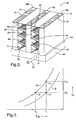
- the psychometric chart for the process of cooling the flow of air is shown.
- the curved lines of the chart represent the relative humidity ( ⁇ i ) of the flow of air. Complete saturation occurs in the flow of air at a relative humidity ( ⁇ i ) equal to one.
- the flow of air enters the evaporative cooler 30 having an initial temperature (T i ) and an initial absolute humidity level ( ⁇ i ) represented in Figure 3 at point "A".
- T i initial temperature
- ⁇ i initial absolute humidity level
- the primary flow of air passes through the dry channel 60 where the convoluted fin 62 absorbs heat from the primary flow of air, thereby lowering the temperature of the flow of air exiting the dry channel 60 of the evaporative cooler 30 without changing the absolute humidity.
- the primary flow of air exiting the evaporative cooler 30 is represented in Figure 3 at point "B", and includes an outflow temperature (T o ), but maintains the initial absolute humidity level ( ⁇ i ).
- the secondary airflow passes through the wet channel 68 of the evaporative cooler 30 without absorbing any heat. However, as discussed above, the secondary airflow picks up moisture from the evaporative cooler 30 as the liquid evaporates into the secondary airflow.
- the secondary airflow exiting the evaporative cooler 30 is represented in Figure 3 at point "C", and includes an outflow absolute humidity level ( ⁇ s ), but maintains the initial temperature (T i ). Accordingly, the primary flow of air which exits the evaporative cooler 30 has a lower temperature than the flow of air entering the evaporative cooler 30, but maintains the same volume of moisture, i.e., absolute humidity level ( ⁇ i ). Therefore, the evaporative cooler 30 has cooled the flow of air that is circulated across the electronic devices 22 without adding any moisture into the air that may damage the electronic devices 22.
Landscapes
- Engineering & Computer Science (AREA)
- Physics & Mathematics (AREA)
- Thermal Sciences (AREA)
- General Engineering & Computer Science (AREA)
- Mechanical Engineering (AREA)
- Geometry (AREA)
- Computer Hardware Design (AREA)
- Microelectronics & Electronic Packaging (AREA)
- Cooling Or The Like Of Electrical Apparatus (AREA)
Abstract
Description
- The subject invention relates to a cabinet for supporting a plurality of electronic devices therein.
- Electronics cabinets store and organize multiple electronic devices, such as computer data servers, in a central location. The electronic devices produce heat that accumulates inside of the cabinet, which may damage the electronic devices stored therein. The amount of heat that each of the electronic devices produces may vary within the cabinet, with some of the electronic devices producing more heat than others. Accordingly, the electronics cabinet may include a system for removing the heat from within the cabinet to maintain an optimum working environment for the electronic devices.
-
U.S. Patent No. 6,506,111 to Sharp et. al. discloses an electronics cabinet for storing a plurality of electronic devices and a system for removing heat from within the cabinet. The cabinet is enclosed and includes a plurality of supports disposed within the cabinet for supporting the electronic devices. An air movement device, such as a fan, is disposed at the bottom of the cabinet for circulating a flow of air through the enclosure. A heat exchanger is disposed at the bottom of the cabinet for transferring the heat stored in the flow of air to a heat exchange medium passing through the heat exchanger. The heat exchange medium is disposed within a closed loop that circulates the heat exchange medium to a remote location from the electronics cabinet to remove the heat stored in the heat exchange medium. A cold air plenum is disposed within the cabinet and extends upwardly adjacent the electronic devices along a first side wall of the cabinet. A plurality of outlets is disposed in the cold air plenum with at least one of the plurality of outlets adjacent each of the supports for directing a portion of the flow of air into each of the supports. A warm air plenum is disposed within the cabinet and extends upwardly adjacent the electronic devices along a second side wall across from the cold air plenum. The warm air plenum receives the flow of air from the supports and directs the flow of air back to the heat exchanger. The air movement device draws the air from the warm air plenum and circulates the air through the heat exchanger to remove the heat therefrom. The flow of air is then directed into the cold air plenum and across the electronic devices, absorbing heat produced from the electronic devices, before entering the warm air plenum where the flow of air is re-circulated within the cabinet. - The subject invention provides a cabinet for supporting a plurality of electronic devices therein. The cabinet includes an enclosure and a plurality of supports disposed within said enclosure for supporting the electronic devices thereon. An air movement device draws a flow of air into the enclosure and circulates the flow of air through the enclosure. A cold air plenum is disposed within the enclosure and includes an inlet for receiving the flow of air from the air movement device and a flexible wall defining a cross-sectional area of the cold air plenum. A plurality of outlets is disposed along the cold air plenum with at least one of the plurality of outlets adjacent each of the supports for directing a portion of the flow of air at each of the supports. An evaporative cooler is disposed within the cabinet for absorbing heat from the flow of air. The evaporative cooler dissipates the heat stored therein by evaporating a liquid disposed on the evaporative cooler into a secondary airflow directed out of the enclosure. The cabinet includes an actuator for moving the flexible wall to change the cross-sectional area of the cold air.
- Accordingly, the evaporative cooler removes heat from the flow of air without expending any additional energy. Additionally, the amount of air supplied to each of the supports may be varied to accommodate the specific design requirements of each of the electronic devices. Therefore the cabinet provides a more efficient system for removing heat from within the cabinet.
- Other advantages of the present invention will be readily appreciated, as the same becomes better understood by reference to the following detailed description when considered in connection with the accompanying drawings wherein:
- Figure 1 is a schematic cross-sectional view of a cabinet;
- Figure 2 is a perspective view of an evaporative cooler; and
- Figure 3 is a psychrometric chart representing the evaporative cooling system of the cabinet.
- Referring to the Figures, wherein like numerals indicate corresponding parts throughout the several views, a cabinet is shown in Figures 1 and 4 generally at 20.
- Referring to Figure 1, the
cabinet 20 is for supporting a plurality ofelectronic devices 22 therein. Theelectronic devices 22 are typically computer data servers, but thecabinet 20 may be utilized to support anyelectronic device 22 and should not be limited to the type of device stored therein. - The
cabinet 20 includes anenclosure 26 and a plurality ofsupports 24 disposed within theenclosure 26 for supporting theelectronic devices 22 thereon. Theenclosure 26 includes a plurality of outer walls, which surround theelectronic devices 22 stored within thecabinet 20. Thesupports 24 may include a plurality of brackets, with theelectronic devices 22 attached thereto. Alternatively, as depicted in Figure 1, thesupports 24 may include a plurality of shelves extending between the walls of theenclosure 26. Thecabinet 20 is divided into an upper portion and a lower portion with theelectronic devices 22 supported in the upper portion. - An
air movement device 28 is disposed within the lower portion of thecabinet 20. Theair movement device 28 draws a flow of ambient air into theenclosure 26 and circulates the flow of air through theenclosure 26. Theair movement device 28 is typically an electric fan; however, any device capable of circulating the flow of air through thecabinet 20 may be utilized. - The
cabinet 20 includes anevaporative cooler 30 and aliquid supply line 32 in fluid communication with theevaporative cooler 30 for supplying theevaporative cooler 30 with a liquid. The liquid is preferably water; however, any suitable liquid may be utilized and the scope of the invention is not limited to the type of liquid. Avalve 34 is provided for opening and closing theliquid supply line 32 to control the flow of the liquid to theevaporative cooler 30. Thevalve 34 is controlled to only allow the liquid to flow into theevaporative cooler 30 when necessary to maintain a pre-determined water level. Thevalve 34 only permits liquid into theevaporative cooler 30 to replenish the liquid that is used during an evaporation process for dissipating heat from theevaporative cooler 30, which is described below. - A
cold air plenum 38 is disposed within the upper portion of thecabinet 20 and is adjacent thesupports 24. Thecold air plenum 38 includes aninlet 40 for receiving the flow of air from theair movement device 28 and aterminal wall 42 spaced from theinlet 40. A flexible wall 44 defines a cross-sectional area of thecold air plenum 38 and extends from the inlet 40 a length to theterminal wall 42. A plurality ofoutlets 46 is disposed along the length of the flexible wall 44 with at least one of the plurality ofoutlets 46 adjacent each of thesupports 24 for directing a portion of the flow of air at each of thesupports 24. - A
warm air plenum 48 is disposed within the upper portion of thecabinet 20 and adjacent thesupports 24, across from thecold air plenum 38. Thewarm air plenum 48 receives the flow of air from thesupports 24 and exhausts the flow of air from thecabinet 20. Accordingly, thecabinet 20 does not re-circulate the flow of air. - The
cabinet 20 includes anactuator 50 for moving the flexible wall 44 closer to or farther from thesupports 24 to change the cross-sectional area of thecold air plenum 38. Theactuator 50 may include a plurality ofactuators 50 with at least one of the plurality ofactuators 50 adjacent each of thesupports 24. Accordingly, the cross sectional area adjacent each of the plurality ofsupports 24 may be changed to accommodate any specific design requirements of theelectronic devices 22 stored thereon. As shown, the flexible wall 44 includes alower roller 51 and anupper roller 53 for tensioning the flexible wall 44. It is contemplated that any excess length of the flexible wall 44 may be wrapped around one or both of the rollers. - The flexible wall 44 provides the optimum airflow to all of the plurality of
supports 24 by utilizing the available flow of air provided by theair movement device 28 in the most efficient manner. Each of thesupports 24 includes an optimum temperature change (ΔTopt ) in the flow of air therethrough, defined by the equation:
where ΔTopt is the optimum temperature (°F) change in any of the plurality ofsupports 24, gc is the gravitational constant
supports 24, η is the dimensionless efficiency of theair movement device 28, q̇ is the heat generation rate
supports 24, Q̇ is the total heat generation rate
supports 24, P is the power
air movement device 28, l is the length (ft) of one of thesupports 24 between thecold air plenum 38 and thewarm air plenum 48, d is the hydraulic diameter (ft) of one of thesupports 24, A is the cross sectional area (ft 2) of one of thesupports 24, ρ is the density

- It should be understood that in the typical application, each of the
electronic devices 22 produces a varying amount of heat and requires a different amount of air flowing through therespective supports 24 to remove the heat. In this situation, the cross-sectional area of thecold air plenum 38 will have a variable rate of change, with the cross-sectional area varying in size along the length of the flexible wall 44. - In limited applications, however, each of the
electronic devices 22 produces the same amount of heat and requires the same amount of air flowing through therespective supports 24 to remove the heat. In this application, the cross-sectional area of thecold air plenum 38 will have a constant rate of change, with the cross-sectional area decreasing in size along the length of the flexible wall 44. Accordingly, the flexible wall 44 has a smaller cross-sectional area adjacent theterminal wall 42 than the cross-sectional area adjacent theinlet 40. In this limited application, the volume of air flowing through thecold air plenum 38 must be greater than or equal to the sum of the volume of air flowing through each of thesupports 24. Based on this consideration, the dimension of thecold air plenum 38 are preferably in the range defined by the equation:
where l is the length (ft) of one of thesupports 24 between thecold air plenum 38 and thewarm air plenum 48, a is the width (ft) of thecold air plenum 38 adjacent theinlet 40, and b is the width (ft) of thecold air plenum 38 adjacent theterminal wall 42. - Utilizing Equation 1, the optimal cross-sectional area of the
cold air plenum 38 adjacent each of the plurality ofsupports 24 may be determined in the following manner. As a first step, beginning at the top of thecabinet 20, determine a temperature difference (ΔT) in the flow of air entering and leaving thesupport 24. If the temperature difference (ΔT) is greater than the optimum temperature change (ΔTopt ) calculated from Equation 1, theactuator 50 is used to increase the cross-sectional area of thecold air plenum 38 by moving the flexible wall 44 away from theoutlet 46 of thecold air plenum 38 adjacent therespective support 24. This will increase the flow of air into thesupport 24, lowering the temperature difference (ΔT) and bringing it closer to the optimum temperature change (ΔTopt ). If the temperature difference (ΔT) is lower than the optimum temperature change (ΔTopt ) calculated from Equation 1, theactuator 50 is used to decrease the cross-sectional area of thecold air plenum 38 by moving the flexible wall 44 toward theoutlet 46 of thecold air plenum 38 adjacent therespective support 24. This will decrease the flow of air into thesupport 24 thereby raising the temperature difference (ΔT) bringing it closer to the optimum temperature change (ΔTopt ). This procedure is repeated sequentially from thesupport 24 closest the top of thecabinet 20 toward thesupport 24 closest the bottom of thecabinet 20. An additional iteration may be required to fine tune the adjustment of the flexible wall 44 to achieve the optimum temperature change (ΔTopt ) for all of theelectronic devices 22 in each of thesupports 24. - The
evaporative cooler 30 is disposed within the lower portion of thecabinet 20. Referring to Figure 2, theevaporative cooler 30 includes abase 54, afirst wall 56, and asecond wall 58 extending upwardly from thebase 54. Thefirst wall 56 and thesecond wall 58 define adry channel 60 therebetween for receiving the flow of air from theair movement device 28. Thedry channel 60 includes aconvoluted fin 62 for absorbing heat from the flow of air and conducting the heat to thefirst wall 56 and thesecond wall 58. Theconvoluted fin 62 includes a plurality oflouvers 64 for creating turbulence in the flow of air crossing theconvoluted fin 62 to increase a heat transfer rate between the flow of air and theconvoluted fin 62. Thebase 54 of theevaporative cooler 30 includes atank 66 for storing the liquid therein. Thetank 66 is in fluid communication with and receives the liquid from theliquid supply line 32. At least one of thefirst wall 56 and thesecond wall 58 define awet channel 68 therein with thewet channel 68 in fluid communication with thetank 66. Thewet channel 68 includes a wickingmaterial 70 for drawing the liquid from thetank 66 and into thewet channel 68. Thefirst wall 56 and thesecond wall 58 define at least oneopening 71 interconnecting thedry channel 60 and thewet channel 68 for directing a portion of the flow of air into thewet channel 68 to provide a secondary airflow through thewet channel 68 and a primary flow of air through thedry channel 60. Thewet channel 68 includes anexit 73 for directing the secondary airflow from thewet channel 68 to thewet scrubber 72 and out of theenclosure 26. - Accordingly, the flow of air enters the
dry channel 60 of theevaporative cooler 30 where theconvoluted fin 62 absorbs heat from the flow of air as the flow of air passes over theconvoluted fin 62. Theconvoluted fin 62 transfers the heat absorbed to the first and thesecond walls wet channel 68 through theopenings 71 interconnecting thedry channel 60 and thewet channel 68. The liquid present in the wickingmaterial 70 of thewet channel 68 evaporates into the secondary airflow, dissipating the heat from theevaporative cooler 30 into the secondary airflow. The secondary airflow is then directed through theexit 73 and out of thecabinet 20 via thewet scrubber 72. The cooled primary flow of air is directed to thecold air plenum 38 as described above. - A
wet scrubber 72 is disposed within the lower portion of thecabinet 20 for removing particulate matter from the flow of air drawn into thecabinet 20. The secondary airflow from theevaporative cooler 30 flows through thewet scrubber 72 as the secondary airflow is directed out of thecabinet 20. The secondary airflow includes moisture from the evaporation of the liquid, which helps attract contaminants from the incoming flow of ambient air. - Referring to Figure 3, the psychometric chart for the process of cooling the flow of air is shown. The curved lines of the chart represent the relative humidity (Φi) of the flow of air. Complete saturation occurs in the flow of air at a relative humidity (Φi) equal to one. The flow of air enters the
evaporative cooler 30 having an initial temperature (Ti) and an initial absolute humidity level (ωi) represented in Figure 3 at point "A". As mentioned above, theevaporative cooler 30 separates the incoming flow of air into the primary flow of air and the secondary airflow. The primary flow of air passes through thedry channel 60 where theconvoluted fin 62 absorbs heat from the primary flow of air, thereby lowering the temperature of the flow of air exiting thedry channel 60 of theevaporative cooler 30 without changing the absolute humidity. The primary flow of air exiting theevaporative cooler 30 is represented in Figure 3 at point "B", and includes an outflow temperature (To), but maintains the initial absolute humidity level (ωi). The secondary airflow passes through thewet channel 68 of theevaporative cooler 30 without absorbing any heat. However, as discussed above, the secondary airflow picks up moisture from theevaporative cooler 30 as the liquid evaporates into the secondary airflow. The secondary airflow exiting theevaporative cooler 30 is represented in Figure 3 at point "C", and includes an outflow absolute humidity level (ωs), but maintains the initial temperature (Ti). Accordingly, the primary flow of air which exits theevaporative cooler 30 has a lower temperature than the flow of air entering theevaporative cooler 30, but maintains the same volume of moisture, i.e., absolute humidity level (ωi). Therefore, theevaporative cooler 30 has cooled the flow of air that is circulated across theelectronic devices 22 without adding any moisture into the air that may damage theelectronic devices 22. - The foregoing invention has been described in accordance with the relevant legal standards; thus, the description is exemplary rather than limiting in nature. Variations and modifications to the disclosed embodiment may become apparent to those skilled in the art and do come within the scope of the invention. Accordingly, the scope of legal protection afforded this invention can only be determined by studying the following claims.
Claims (19)
- A cabinet (20) for supporting a plurality of electronic devices (22) therein, said cabinet (20) comprising:an enclosure (26);a plurality of supports (24) disposed within said enclosure (26) for supporting the electronic devices (22) thereon;an air movement device (28) for drawing a flow of air into said enclosure (26) and circulating the flow of air through said enclosure (26);a cold air plenum (38) disposed within said enclosure (26) and including an inlet (40) for receiving the flow of air from said air movement device (28) and a flexible wall (44) defining a cross-sectional area of said cold air plenum (38);a plurality of outlets (46) disposed along said cold air plenum (38) with at least one of said plurality of outlets (46) adjacent each of said supports (24) for directing a portion of the flow of air at each of said supports (24); andan evaporative cooler (30) disposed within said cabinet (20) for absorbing heat from the flow of air and for dissipating the heat stored therein by evaporating a liquid disposed on said evaporative cooler (30) into a secondary airflow directed out of said enclosure (26).
- A cabinet (20) as set forth in claim 1 wherein said cabinet (20) includes an actuator (50) for moving said flexible wall (44) to change said cross-sectional area of said cold air plenum (38).
- A cabinet (20) as set forth in claim 2 wherein said cabinet (20) includes a roller for tensioning said flexible wall (44).
- A cabinet (20) as set forth in claim 3 wherein said actuator (50) includes a plurality of actuators (50) with at least one of said plurality of actuators (50) adjacent each of said supports (24) for moving said flexile wall to change said cross-sectional area of said cold air plenum (38) relative to each of said plurality of supports (24).
- A cabinet (20) as set forth in claim 4 wherein each of said supports (24) includes an optimum temperature change (ΔTopt ) in the flow of air therethrough defined by the equation:

where gc is a gravitational constant, f is a dimensionless friction factor in each of said supports (24), η is a dimensionless efficiency of the air movement device (28), q̇ is a heat generation rate in on of said supports (24), Q̇ is a total heat generation rate of all of said plurality of supports (24), P is a power of said air movement device (28), l is a length of said plurality of supports (24), d is a hydraulic diameter of said plurality of supports (24), A is a cross sectional area of said plurality of supports (24), ρ is a density of the flow of air, cp is an isobaric specific heat of the flow of air. - A cabinet (20) as set forth in claim 2 wherein said cabinet (20) includes a liquid supply line (32) in fluid communication with said evaporative cooler (30) for supplying said evaporative cooler (30) with the liquid.
- A cabinet (20) as set forth in claim 6 wherein said cabinet (20) includes a valve (34) for opening (36) and closing said liquid supply line (32) to control the flow of the liquid to said evaporative cooler (30).
- A cabinet (20) as set forth in claim 7 wherein said evaporative cooler (30) includes a base (54) and a first wall (56) and a second wall (58) extending upwardly from said base (54) and defining a dry channel (60) between said first wall (56) and said second wall (58) for receiving the flow of air from said air movement device (28).
- A cabinet (20) as set forth in claim 8 wherein said dry channel (60) includes a convoluted fin (62) for absorbing heat from the flow of air and conducting the heat to said first wall (56) and said second wall (58).
- A cabinet (20) as set forth in claim 9 wherein said convoluted fin (62) includes a plurality of louvers (64) for creating turbulence in the flow of air crossing said convoluted fin (62).
- A cabinet (20) as set forth in claim 10 wherein said base (54) of said evaporative cooler (30) includes a tank (66) for storing the liquid therein.
- A cabinet (20) as set forth in claim 11 wherein at least one of said first wall (56) and said second wall (58) define a wet channel (68) therein with said wet channel (68) in fluid communication with said tank (66).
- A cabinet (20) as set forth in claim 12 wherein said wet channel (68) includes a wicking material (70) for drawing the liquid from said tank (66) into said wet channel (68).
- A cabinet (20) as set forth in claim 13 wherein at least one of said first wall (56) and said second wall (58) define at least one opening (71) interconnecting said dry channel (60) and said wet channel (68) for directing a portion of the flow of air into said wet channel (68) to provide a secondary airflow through said wet channel (68).
- A cabinet (20) as set forth in claim 14 wherein said cold air plenum (38) includes a terminal wall (42) spaced from said inlet (40) and said flexible wall (44) extends from said inlet (40) a length to said terminal wall (42) with said cross-sectional area of said cold air plenum (38) decreasing in size along said length of said flexible wall (44) and said flexible wall (44) having a smaller cross-sectional area adjacent said terminal wall (42) then adjacent said inlet (40).
- A cabinet (20) as set forth in claim 15 wherein said cold air plenum (38) includes a first width (a), a second width (b), and a length (l) in the range defined by the equation:
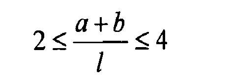
where l is the length of one of said plurality of supports (24), a is said first width of said cold air plenum (38) adjacent said inlet (40), and b is said second width of said cold air plenum (38) adjacent said terminal wall (42). - A cabinet (20) as set forth in claim 14 wherein said cabinet (20) includes a warm air plenum (48) for receiving the flow of air from said supports (24) and exhausting the flow of air from said cabinet (20).
- A cabinet (20) as set forth in claim 17 wherein said cabinet (20) includes a wet scrubber (72) for removing particulate matter from the flow of air drawn into said cabinet (20).
- A cabinet (20) as set forth in claim 18 wherein said wet channel (68) includes an exit (73) for directing the secondary airflow from said wet channel (68) to said wet scrubber (72) and out of said enclosure (26).
Applications Claiming Priority (1)
| Application Number | Priority Date | Filing Date | Title |
|---|---|---|---|
| US11/242,731 US7438124B2 (en) | 2005-10-04 | 2005-10-04 | Evaporative cooling system for a data-communications cabinet |
Publications (2)
| Publication Number | Publication Date |
|---|---|
| EP1773107A2 true EP1773107A2 (en) | 2007-04-11 |
| EP1773107A3 EP1773107A3 (en) | 2009-08-26 |
Family
ID=37684462
Family Applications (1)
| Application Number | Title | Priority Date | Filing Date |
|---|---|---|---|
| EP06076728A Withdrawn EP1773107A3 (en) | 2005-10-04 | 2006-09-18 | Evaporative cooling system for a data-communications cabinet |
Country Status (2)
| Country | Link |
|---|---|
| US (1) | US7438124B2 (en) |
| EP (1) | EP1773107A3 (en) |
Cited By (3)
| Publication number | Priority date | Publication date | Assignee | Title |
|---|---|---|---|---|
| EP2247994A4 (en) * | 2008-02-15 | 2013-10-16 | Hewlett Packard Development Co | PULSE EMISSION OF A COOLING AGENT FOR A COMPUTER SYSTEM |
| CN103776201A (en) * | 2014-02-13 | 2014-05-07 | 天津商业大学 | Condensing evaporator capable of regulating heat exchange area and tube bundle arrangement mode |
| CN104918462A (en) * | 2015-06-16 | 2015-09-16 | 浙江中烟工业有限责任公司 | Cabinet cooing system for servers of cloud computing computer room |
Families Citing this family (32)
| Publication number | Priority date | Publication date | Assignee | Title |
|---|---|---|---|---|
| US7542287B2 (en) | 2005-09-19 | 2009-06-02 | Chatsworth Products, Inc. | Air diverter for directing air upwardly in an equipment enclosure |
| US8107238B2 (en) | 2005-09-19 | 2012-01-31 | Chatsworth Products, Inc. | Ducted exhaust equipment enclosure |
| US11259446B2 (en) | 2005-09-19 | 2022-02-22 | Chatsworth Products, Inc. | Vertical exhaust duct for electronic equipment enclosure |
| US7804685B2 (en) | 2005-09-19 | 2010-09-28 | Chatsworth Products, Inc. | Ducted exhaust equipment enclosure |
| US11212928B2 (en) | 2005-09-19 | 2021-12-28 | Chatsworth Products, Inc. | Vertical exhaust duct for electronic equipment enclosure |
| US20070171610A1 (en) * | 2006-01-20 | 2007-07-26 | Chatsworth Products, Inc. | Internal air duct |
| US8257155B2 (en) * | 2006-01-20 | 2012-09-04 | Chatsworth Products, Inc. | Selectively routing air within an electronic equipment enclosure |
| US20110123036A1 (en) * | 2006-03-02 | 2011-05-26 | Yossi Barath | Muffled rack and methods thereof |
| US9496200B2 (en) | 2011-07-27 | 2016-11-15 | Coolit Systems, Inc. | Modular heat-transfer systems |
| US7644983B2 (en) * | 2007-10-18 | 2010-01-12 | Delphi Technologies, Inc. | Evaporatively pre-cooled seat assembly |
| US10133320B2 (en) | 2008-02-14 | 2018-11-20 | Chatsworth Products, Inc. | Air directing device |
| DE102008036755A1 (en) * | 2008-08-07 | 2010-02-11 | Baldwin Germany Gmbh | Switch cabinet for accommodating e.g. electrical and/or electronic component, has passage opening and channel section designed for installation of radial fan, such that recirculation air flow is generated from radial fan |
| WO2010018398A2 (en) * | 2008-08-13 | 2010-02-18 | Bae Systems Plc | Equipment cooling |
| US7646602B1 (en) | 2008-08-29 | 2010-01-12 | Qlogic, Corporation | Apparatus and methods for cooling network switches |
| US7675750B1 (en) * | 2008-08-29 | 2010-03-09 | Qlogic, Corporation | Apparatus and methods for cooling networks switches |
| US20100141105A1 (en) * | 2008-12-04 | 2010-06-10 | Thermocabinet, Llc | Thermal Management Cabinet for Electronic Equipment |
| EP2205054A1 (en) * | 2009-01-05 | 2010-07-07 | Chatsworth Product, INC. | Electronic equipment enclosure with side-to-side airflow control system |
| US8197124B2 (en) * | 2009-02-05 | 2012-06-12 | International Business Machines Corporation | Heat flow measurement tool for a rack mounted assembly of electronic equipment |
| US8653363B2 (en) | 2010-06-01 | 2014-02-18 | Chatsworth Products, Inc. | Magnetic filler panel for use in airflow control system in electronic equipment enclosure |
| ES2769605T3 (en) | 2010-08-26 | 2020-06-26 | Asetek Danmark As | Liquid cooling system for a server |
| JP5315323B2 (en) * | 2010-11-17 | 2013-10-16 | アラクサラネットワークス株式会社 | Electronic equipment |
| CN102742375B (en) * | 2010-12-07 | 2015-06-10 | 北京纳源丰科技发展有限公司 | A refrigeration integrated cabinet |
| US9155230B2 (en) | 2011-11-28 | 2015-10-06 | Asetek Danmark A/S | Cooling system for a server |
| JP5850161B2 (en) * | 2012-08-09 | 2016-02-03 | 富士通株式会社 | Heat receiving device, cooling device, and electronic device |
| EP2762796A1 (en) * | 2013-02-04 | 2014-08-06 | ABB Oy | Cooling assembly |
| JP5969939B2 (en) * | 2013-02-28 | 2016-08-17 | 株式会社日立製作所 | Data center air conditioning controller |
| CN103486896B (en) * | 2013-07-30 | 2015-05-27 | 杭州三花微通道换热器有限公司 | Manifold assembly and heat exchanger with same |
| KR102506845B1 (en) * | 2016-12-02 | 2023-03-08 | 현대자동차주식회사 | Air condition control apparatus and fuel cell system comprising the same |
| US11978875B2 (en) | 2017-01-03 | 2024-05-07 | Lg Energy Solution, Ltd. | System for cooling components arranged within an enclosure |
| US11452243B2 (en) | 2017-10-12 | 2022-09-20 | Coolit Systems, Inc. | Cooling system, controllers and methods |
| US20230055085A1 (en) * | 2021-08-18 | 2023-02-23 | Mathew Zaagsma | Cooling Electronic Cabinet Assembly |
| US12200914B2 (en) | 2022-01-24 | 2025-01-14 | Coolit Systems, Inc. | Smart components, systems and methods for transferring heat |
Family Cites Families (9)
| Publication number | Priority date | Publication date | Assignee | Title |
|---|---|---|---|---|
| US3253646A (en) * | 1964-04-08 | 1966-05-31 | Udylite Corp | Cooling system for power supply apparatus |
| SE383777B (en) * | 1973-07-18 | 1976-03-29 | Munters Ab Carl | KIT AND DEVICE FOR AIR COOLING |
| DE2635445C3 (en) * | 1976-08-06 | 1979-07-12 | Zweites Deutsches Fernsehen, Anstalt Des Oeffentlichen Rechts, 6500 Mainz | Device for removing heat from devices |
| US5226590A (en) * | 1992-01-15 | 1993-07-13 | Raymond K. Davis | Adaptor for mounting temperature sensitive duty cycling control with flexible duct work |
| US5740018A (en) * | 1996-02-29 | 1998-04-14 | The United States Of America As Represented By The Secretary Of The Navy | Environmentally controlled circuit pack and cabinet |
| AU2002220199A1 (en) * | 2000-11-09 | 2002-05-21 | Jay D. Ray | Raised floor air handling unit |
| US6506111B2 (en) | 2001-05-16 | 2003-01-14 | Sanmina-Sci Corporation | Cooling airflow distribution device |
| US7170745B2 (en) * | 2003-04-30 | 2007-01-30 | Hewlett-Packard Development Company, L.P. | Electronics rack having an angled panel |
| US7075788B2 (en) * | 2003-06-11 | 2006-07-11 | Hewlett-Packard Development Company, L.P. | Computer cooling system and method |
-
2005
- 2005-10-04 US US11/242,731 patent/US7438124B2/en not_active Expired - Fee Related
-
2006
- 2006-09-18 EP EP06076728A patent/EP1773107A3/en not_active Withdrawn
Cited By (3)
| Publication number | Priority date | Publication date | Assignee | Title |
|---|---|---|---|---|
| EP2247994A4 (en) * | 2008-02-15 | 2013-10-16 | Hewlett Packard Development Co | PULSE EMISSION OF A COOLING AGENT FOR A COMPUTER SYSTEM |
| CN103776201A (en) * | 2014-02-13 | 2014-05-07 | 天津商业大学 | Condensing evaporator capable of regulating heat exchange area and tube bundle arrangement mode |
| CN104918462A (en) * | 2015-06-16 | 2015-09-16 | 浙江中烟工业有限责任公司 | Cabinet cooing system for servers of cloud computing computer room |
Also Published As
| Publication number | Publication date |
|---|---|
| US7438124B2 (en) | 2008-10-21 |
| EP1773107A3 (en) | 2009-08-26 |
| US20070074866A1 (en) | 2007-04-05 |
Similar Documents
| Publication | Publication Date | Title |
|---|---|---|
| US7438124B2 (en) | Evaporative cooling system for a data-communications cabinet | |
| US20250257952A1 (en) | Gas cooled condensers for loop heat pipe like enclosure cooling | |
| KR100376749B1 (en) | Low profile heat exchange system and method with reduced water consumption | |
| US10260818B2 (en) | Cooling system and method of cooling an interior space | |
| EP2834569B1 (en) | Controlling data center cooling | |
| EP3204697B1 (en) | Air handling unit and method of operating the same | |
| US7660117B2 (en) | Deformable duct guides that accommodate electronic connection lines | |
| DK2032907T3 (en) | Hot cooling for electronics | |
| EP1903849B1 (en) | Apparatus and method for cooling a space in a data center by means of recirculation air | |
| EP2198682B1 (en) | Recirculating gas rack cooling architecture | |
| US7864527B1 (en) | Systems and methods for close coupled cooling | |
| US9158345B1 (en) | Managing computer performance | |
| US9760098B1 (en) | Cooling a data center | |
| US5688169A (en) | Electrical equipment cabinet cooling | |
| CN100587346C (en) | Air cooling and air dehumidification module including capillary mat and method of use thereof | |
| TWM367568U (en) | Heat dissipation device, and electronic component module box and machine room with the same | |
| KR102879743B1 (en) | Rooftop solar panel cooling system | |
| WO2003073013A1 (en) | Air conditioning device and method | |
| Sathyanarayan et al. | Steady state CFD modeling of an IT pod and its cooling system | |
| KR20160082296A (en) | Apparatus for cooling server rack | |
| US10830541B2 (en) | Outdoor electronics enclosure with dual heat exchangers | |
| DE202006017196U1 (en) | A heat exchanger for the condenser or evaporator of an air conditioning system has plastic tubing within a housing which has air circulation openings at the top and bottom | |
| HK1207147B (en) | Controlling data center cooling | |
| JPS63141820A (en) | Warming device for vehicle |
Legal Events
| Date | Code | Title | Description |
|---|---|---|---|
| PUAI | Public reference made under article 153(3) epc to a published international application that has entered the european phase |
Free format text: ORIGINAL CODE: 0009012 |
|
| AK | Designated contracting states |
Kind code of ref document: A2 Designated state(s): AT BE BG CH CY CZ DE DK EE ES FI FR GB GR HU IE IS IT LI LT LU LV MC NL PL PT RO SE SI SK TR |
|
| AX | Request for extension of the european patent |
Extension state: AL BA HR MK YU |
|
| PUAL | Search report despatched |
Free format text: ORIGINAL CODE: 0009013 |
|
| AK | Designated contracting states |
Kind code of ref document: A3 Designated state(s): AT BE BG CH CY CZ DE DK EE ES FI FR GB GR HU IE IS IT LI LT LU LV MC NL PL PT RO SE SI SK TR |
|
| AX | Request for extension of the european patent |
Extension state: AL BA HR MK RS |
|
| AKX | Designation fees paid | ||
| REG | Reference to a national code |
Ref country code: DE Ref legal event code: 8566 |
|
| STAA | Information on the status of an ep patent application or granted ep patent |
Free format text: STATUS: THE APPLICATION IS DEEMED TO BE WITHDRAWN |
|
| 18D | Application deemed to be withdrawn |
Effective date: 20100227 |