EP1772884A2 - Electromagnetic relay - Google Patents
Electromagnetic relay Download PDFInfo
- Publication number
- EP1772884A2 EP1772884A2 EP06020871A EP06020871A EP1772884A2 EP 1772884 A2 EP1772884 A2 EP 1772884A2 EP 06020871 A EP06020871 A EP 06020871A EP 06020871 A EP06020871 A EP 06020871A EP 1772884 A2 EP1772884 A2 EP 1772884A2
- Authority
- EP
- European Patent Office
- Prior art keywords
- external connecting
- fixed contact
- contact
- base
- electromagnetic relay
- Prior art date
- Legal status (The legal status is an assumption and is not a legal conclusion. Google has not performed a legal analysis and makes no representation as to the accuracy of the status listed.)
- Granted
Links
Images


Classifications
-
- H—ELECTRICITY
- H01—ELECTRIC ELEMENTS
- H01H—ELECTRIC SWITCHES; RELAYS; SELECTORS; EMERGENCY PROTECTIVE DEVICES
- H01H50/00—Details of electromagnetic relays
- H01H50/14—Terminal arrangements
-
- H—ELECTRICITY
- H01—ELECTRIC ELEMENTS
- H01H—ELECTRIC SWITCHES; RELAYS; SELECTORS; EMERGENCY PROTECTIVE DEVICES
- H01H51/00—Electromagnetic relays
- H01H51/02—Non-polarised relays
- H01H51/04—Non-polarised relays with single armature; with single set of ganged armatures
-
- H—ELECTRICITY
- H01—ELECTRIC ELEMENTS
- H01H—ELECTRIC SWITCHES; RELAYS; SELECTORS; EMERGENCY PROTECTIVE DEVICES
- H01H50/00—Details of electromagnetic relays
- H01H50/16—Magnetic circuit arrangements
- H01H50/36—Stationary parts of magnetic circuit, e.g. yoke
- H01H2050/362—Part of the magnetic circuit conducts current to be switched or coil current, e.g. connector and magnetic circuit formed of one single part
-
- H—ELECTRICITY
- H01—ELECTRIC ELEMENTS
- H01H—ELECTRIC SWITCHES; RELAYS; SELECTORS; EMERGENCY PROTECTIVE DEVICES
- H01H50/00—Details of electromagnetic relays
- H01H50/02—Bases; Casings; Covers
- H01H50/04—Mounting complete relay or separate parts of relay on a base or inside a case
-
- H—ELECTRICITY
- H01—ELECTRIC ELEMENTS
- H01H—ELECTRIC SWITCHES; RELAYS; SELECTORS; EMERGENCY PROTECTIVE DEVICES
- H01H50/00—Details of electromagnetic relays
- H01H50/54—Contact arrangements
- H01H50/60—Contact arrangements moving contact being rigidly combined with movable part of magnetic circuit
Definitions
- the present invention relates to an electromagnetic relay to be mounted on a printed circuit board or a like and more particularly to the electromagnetic relay to control the switching ON/OFF of a current as comparatively large as about several tens of amperes used in automotive electrical devices, household electrical appliances, or a like.
- Patent Reference 1 Japanese Utility Model Application No. Hei 03-86545
- Patent Reference 1 Japanese Utility Model Application No. Hei 03-86545
- an electromagnet made up of a coil, a core, and a yoke
- an armature which is attracted by the electromagnet
- a movable contact spring to make the armature exert its stability
- a movable contact coupled to a tip of the movable contact spring
- a fixed contact terminal connected electrically to the fixed contact
- a movable contact terminal electrically to the movable contact.
- Some of the movable contact terminal has a configuration being integral with the movable contact spring as shown in Fig. 8 in the Patent Reference 1.
- an object of the present invention to provide an electromagnetic relay which is capable of effectively dissipating heat from a base and of suppressing a rise in temperatures within the electro- magnetic relay.
- an electromagnetic relay including:
- a preferable mode is one wherein the group of external connecting terminals is formed from at least one piece of the plate-shaped conductive material by cutting and bending.
- a preferable mode is one wherein the electrically insulating material includes a resin or ceramic.
- a preferable mode is one wherein the at least one movable contact external connecting terminal is exposed from the base so as to come into direct mechanically contact with part of the yoke.
- a preferable mode is one wherein the at least one fixed contact is mechanically coupled to the at least one fixed contact external connecting terminal by at least one of methods of fitting by pressure, welding, and soldering.
- a preferable mode is one wherein a portion of each of the at least one fixed contact external connecting terminal mechanically coupled to the at least one fixed contact is exposed from the base.
- a preferable mode is one wherein at least one securing body made of a same plate-shaped conductive material as used for the external connecting terminals and mechanically coupled to at least one the fixed contact is provided in the base.
- a preferable mode is one wherein the at least one securing body is molded by a press with part of the at least one securing body being coupled to the group of external connecting terminals and a portion coupled between the at least one securing body and each one of the group of external connecting terminals is removed after the group of external connecting terminals is insert-molded into the base and the at least one securing body and the group of external connecting terminals are in an electrically isolated state.
- a preferable mode is one wherein a portion of the at least one securing body mechanically coupled to the at least one fixed contact and the coupled portion are exposed from the base.
- Still another preferable mode is one wherein the at least one fixed contact includes an ordinarily closed fixed contact or an ordinarily opened fixed contact.
- a preferable mode is one that wherein includes at least one pair of the fixed contacts which includes an ordinarily closed fixed contact and an ordinarily opened fixed contact.
- an electromagnetic relay including:
- the movable contact external connecting terminals are exposed from the base so as to be in direct contact with the yoke extended portion serving as part of the yoke and the movable contact external connecting terminals and the yoke are mechanically coupled to each other by performing a caulking process or welding process on a surface in which the movable contact external connecting terminals and the yoke are in direct contact with one another and, therefore, heat generated in the coil and in the current-carrying path passing from the movable contacts through the movable spring and the yoke can be effectively transferred to the external connecting terminals and to the electrically insulating material portion of the base.
- the group of the external connecting terminals are formed from at least one piece of the plate-shaped conductive material by a cutting and bending process, thereby achieving the ease of handling materials and members.
- the group of external connecting terminals and fixed contacts it makes automation of their fabrication easier to use the plate-shaped conductive material shaped like a reel or like a short strip.
- the fixed contacts when a securing body for securing the fixed contacts which is made up of the same material as used for the external connecting terminals is provided in the base, the fixed contacts can be secured firmly to the base and, due to assembly among the metal materials, production of an abrasion powder from mold materials can be suppressed at time of the assembly.
- the inventors of the present invention have conceived an electromagnetic relay having a configuration to solve this problem.
- a prototype of the electromagnetic relay conceived and built by the inventors includes a core, a coil, a yoke, an armature, an electromagnetic block made up of a movable spring having movable contacts mechanically coupled to the armature, a pair of fixed contacts being in contact with the movable contacts, a group of external connecting terminals made up of a movable contact external connecting terminal, fixed contact external connecting terminal, coil external connecting terminal each being electrically connected respectively to the movable contacts, the pair of fixed contacts, and the coil, a base on which the electromagnetic block, the pair of fixed contacts, and the group of external connecting terminals are mounted and secured, and an armored cover, in which the movable spring, armature, and yoke make up part of a current-carrying path and the group of the external connecting terminals are fabricated from one piece of a plate-shaped conductive material by a cutting and bending process and part of each of the external connecting terminals is insert-molded into the base by using an electrically insulating material such
- the insert-molding is performed on the group of external connecting terminals, a contact area between each of the external connecting terminals and the electrically insulating material is large and excellent contact between each of the external connecting terminals and the electrically insulating material is obtained and, therefore, heat of the group of the external connecting terminals is easily transferred to the entire base, which enables heat to be dissipated from the entire base and, as a result, the rise in temperatures within the electromagnetic relay is suppressed.
- the group of the external connecting terminals and fixed contacts are formed from at least one piece of a plate-shaped conductive material by a cutting and bending process, which achieves the ease of handling materials and members.
- the fixed contacts as in the case of the external connecting terminals, are formed from at least one piece of the plate-shaped conductive material by cutting and bending, pattern designing of the plate-shaped conductive material becomes difficult in some cases. For example, in some cases, it is made difficult to secure space required to cut and erect the fixed contacts to realize a desired arrangement of the connecting terminals. Moreover, in some cases, even when the fixed contacts can be cut and erected from the plate-shaped conductive material, each of the group of the external connecting terminals to be wrapped by the insulating materials on the base becomes small in volume depending on arrangements of the terminals, thus decreasing the effect of dissipating heat from an entire surface of the base.
- FIG. 1 is a perspective view of an electromagnetic relay according to a first embodiment of the present invention.
- the electromagnetic relay includes a core 1, a coil 2, a yoke 3, an armature 4, an electromagnetic block 7 made up of a movable spring 6 having a movable contact 5 mechanically coupled to the armature 4, a pair of fixed contacts made up of an ordinarily closed fixed contact 8a and an ordinarily opened fixed contact 8b both being contact with the movable contact 5 in a manner in which both the fixed contacts 8a and 8b strike the movable contact 5 to come into physical contact, a group of external connecting terminals made up of a movable contact external connecting terminal 11a electrically connected to the movable contact 5, an ordinarily closed fixed contact external connecting terminal 11b electrically connected to the ordinarily closed fixed contact 8a, an ordinarily opened fixed contact external connecting terminal 11c electrically connected to the ordinarily opened fixed contact 8b, and a pair of coil external connecting terminals 11d and 11d, a base 9 on
- the movable spring 6, the armature 4, and the yoke 3 make up part of a current-carrying path and an upper surface of a yoke extended portion 3a making up part of the yoke 3 is in direct contact with the movable contact external connecting terminal 11a and is mechanically coupled to the terminal 11a by a caulking method via a caulking hole 13 (not shown in Fig. 1) .
- the ordinarily closed fixed contact 8a is coupled electrically and thermally to the ordinarily closed fixed contact external connecting terminal 11b by a mechanical coupling portion 15a and is also mechanically connected to a securing body 14a for firm positional fixing.
- the above coupling is achieved by inserting a coupling portion of each of the fixed contacts 8a and 8b by pressure or by securing portions to be coupled using welding, soldering, or a like.
- the ordinarily opened fixed contact 8b is coupled to the ordinarily opened fixed contact terminal connecting terminal 11c and is also mechanically connected to a securing body 14b (not shown) for firm positional fixing.
- Figure 2 is a plan view showing configurations of the base 9 and the group of the external connecting terminals 11a, 11b, 11c, 11d and 11d, showing a state in which each of the external connecting terminals 11a, 11b, 11c, 11d and 11d and each of the securing bodies 14a and 14b are cut and separated from one piece of a metal plate made of copper metal or a like.
- the external connecting terminals 11a, 11b, 11c, 11d and 11d and securing bodies 14a and 14b are secured to the base 9 by an insert-molding method using an electrical insulating material 12 such as a heat-resistant resin, ceramic, or a like.
- the ordinarily closed fixed contact external connecting terminal 11b and the ordinarily opened fixed contact external connecting terminal 11c have, respectively, mechanical coupling portions 15a and 15b used to mechanically couple the fixed contacts 8a and 8b, which are exposed from an upper surface of the base 9, thereby achieving the ease of mechanical coupling.
- the securing body 14a for the ordinarily closed fixed contact 8a and the securing body 14b for the ordinarily opened fixed contact 8b have, respectively, mechanical coupling portions 15c and 15d used to mechanically couple the fixed contacts 8a and 8b which are exposed from the base 9.
- the coupling and securing between the yoke extended portion 3a and the movable contact external connecting terminal 11a are made possible not only by the method of caulking but also by the method of welding, soldering, or a like.
- both the mechanical coupling between each of the fixed contacts 8a and 8b and each of the external connecting terminals 11a, 11b, 11c, 11d and 11d and the coupling between each of the fixed contacts 8a and 8b and each of the securing bodies 14a and 14b are made possible by the method using pressure, the method of welding such as laser welding, arc welding, and resistance welding and by the method of soldering.
- a tip portion serving as a portion in which each of the external connecting terminals 11a, 11b, 11c, 11d and 11d shown in Fig. 1 is connected to the printed circuit board is formed in a state in which the tip portion is bent almost vertically to the base 9 when compared with the state shown in Fig. 2, however, a shape of each tip portion may be of various types used in conventional methods depending on each case of mounting on printed circuit boards.
- the configurations of the electromagnetic relay of the second embodiment differ from those in the first embodiment only in the method of fabricating securing bodies 14a and 14b.
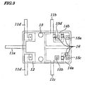
- Figure 3 is a plan view showing configurations of a base and a group of external connecting terminals to be used in the second embodiment. As in the case of Fig. 2, Fig. 3 shows a state in which each external connecting terminal and each securing body are cut and separated from one piece of a metal plate.
- the securing bodies 14a and 14b and the ordinarily opened fixed contact external connecting terminal 11c and ordinarily closed fixed contact external connecting terminal 11b are molded by a press in a state in which each of the securing bodies 14a and 14b is partially coupled to each of the external connecting terminals 11c and 11b and then the insert-molding is carried out.
- Each of coupling portions 16 is exposed from an upper surface of a base 9 and is removed before a pair of fixed contacts and an electromagnetic block are mounted and secured on the base 9.
- the method of removing the coupling portions 16 includes a method of stamping the coupling portions 16 by a press and of cutting the coupling portions 16 by using a laser.
- the electromagnetic relay according to the present invention may include not only one pair but also two or more pairs of the fixed contacts, each pair of which includes an ordinarily closed fixed contact and an ordinarily opened fixed contact.
- one or more fixed contacts are configured as only an ordinarily closed fixed contact configuration, or only an ordinarily opened fixed contact configuration, instead of a pair fixed contact configuration.
- the present invention can be applied mainly to automotive electrical devices which require driving control of a current as large as several tens of amperes such as motors, solenoids, and a like and can be applied also to industrial apparatuses, household electrical appliances, and a like.
Landscapes
- Physics & Mathematics (AREA)
- Electromagnetism (AREA)
- Switch Cases, Indication, And Locking (AREA)
- Contacts (AREA)
- Electromagnets (AREA)
Abstract
Description
- The present invention relates to an electromagnetic relay to be mounted on a printed circuit board or a like and more particularly to the electromagnetic relay to control the switching ON/OFF of a current as comparatively large as about several tens of amperes used in automotive electrical devices, household electrical appliances, or a like.
- The present application claims priority of
Japanese Patent Application No. 2005-292381 filed on October 5, 2005 - An example of a conventional electromagnetic relay to switch conduction for control of a motor, a solenoid, or a like is disclosed in Patent Reference 1 (
Japanese Utility Model Application No. Hei 03-86545 Patent Reference 1. - However, in the conventional electromagnetic relay that carries a current of several tens of amperes for control of a motor, a solenoid, or a like, a rise in temperatures occurs due to heat generated at a contact making up a current-carrying path, terminal, movable spring, or a like and due to heat transferred from the coil. In recent years, there appears a problem that, due to contradictory demands for miniaturization of a relay and for high-capacity (large current) operations of the relay, a rise in temperatures within the relay is inevitable which, as a result, causes operating failures. Therefore, the suppression in the rise in temperatures in the relay is required.
- In view of the above, it is an object of the present invention to provide an electromagnetic relay which is capable of effectively dissipating heat from a base and of suppressing a rise in temperatures within the electro- magnetic relay.
- According to a first aspect of the present invention, there is provided an electromagnetic relay including:
- an electromagnetic block including a core, a coil, a yoke, an armature, and a movable spring having at least one movable contact mechanically coupled to the armature;
- at least one fixed contact associated with the at least one movable contact;
- a group of external connecting terminals including at least one movable contact external connecting terminal, at least one fixed contact external connecting terminal, and at least one coil external connecting terminal being electrically connected respectively to the at least one movable contact, the at least one fixed contact, and the coil;
- a base on which the electromagnetic block, the at least one fixed contact, the group of external connecting terminals are mounted and secured; and
- an armored cover,
- wherein the movable spring, the armature, and the yoke make up part of a current-carrying path;
- wherein the group of external connecting terminals is formed from a plate-shaped conductive material and part of each of the external connecting terminals is insert-molded into the base using an electrically insulating material;
- wherein the at least one movable contact external connecting terminal is exposed from the base so as to come into contact with part of the yoke and the contacted portion of the at least one movable contact external connecting terminal is mechanically coupled and secured to part of the yoke; and
- wherein at least one the fixed contact is mechanically coupled to the at least one fixed contact external connecting terminal.
- In the foregoing first aspect, a preferable mode is one wherein the group of external connecting terminals is formed from at least one piece of the plate-shaped conductive material by cutting and bending.
- Also, a preferable mode is one wherein the electrically insulating material includes a resin or ceramic.
- Also, a preferable mode is one wherein the at least one movable contact external connecting terminal is exposed from the base so as to come into direct mechanically contact with part of the yoke.
- In addition, a preferable mode is one wherein the at least one fixed contact is mechanically coupled to the at least one fixed contact external connecting terminal by at least one of methods of fitting by pressure, welding, and soldering.
- Also, a preferable mode is one wherein a portion of each of the at least one fixed contact external connecting terminal mechanically coupled to the at least one fixed contact is exposed from the base.
- Also, a preferable mode is one wherein at least one securing body made of a same plate-shaped conductive material as used for the external connecting terminals and mechanically coupled to at least one the fixed contact is provided in the base.
- Also, a preferable mode is one wherein the at least one securing body is molded by a press with part of the at least one securing body being coupled to the group of external connecting terminals and a portion coupled between the at least one securing body and each one of the group of external connecting terminals is removed after the group of external connecting terminals is insert-molded into the base and the at least one securing body and the group of external connecting terminals are in an electrically isolated state.
- Furthermore, a preferable mode is one wherein a portion of the at least one securing body mechanically coupled to the at least one fixed contact and the coupled portion are exposed from the base.
- Still another preferable mode is one wherein the at least one fixed contact includes an ordinarily closed fixed contact or an ordinarily opened fixed contact.
- In addition, a preferable mode is one that wherein includes at least one pair of the fixed contacts which includes an ordinarily closed fixed contact and an ordinarily opened fixed contact.
- According to a second aspect of the present invention, there is provided an electromagnetic relay including:
- an electromagnetic block including a core, a coil, a yoke, an armature, and a movable spring having at least one movable contact mechanically coupled to the armature;
- at least one fixed contact associated with the at least one movable contact;
- a group of external connecting terminals including at least one movable contact external connecting terminal, at least one fixed contact external connecting terminal, and at least one coil external connecting terminal being electrically connected respectively to the at least one movable contact, the at least one fixed contact, and the coil;
- a base on which the electromagnetic block, the at least one fixed contact, the group of external connecting terminals are mounted and secured; and
- an armored cover,
- wherein the movable spring, the armature, and the yoke make up part of a current-carrying path;
- wherein the group of external connecting terminals is formed from a plate-shaped conductive material by cutting and bending and part of each of the external connecting terminals is insert-molded into the base using an electrically insulating material including a resin or ceramic;
- wherein the at least one movable contact external connecting terminal is exposed from the base so as to come into direct contact with part of the yoke and the contacted portion of the at least one movable contact external connecting terminal is mechanically coupled and secured to part of the yoke; and
- wherein at least one the fixed contact is mechanically coupled to the at least one fixed contact external connecting terminal.
- With the above configuration, the movable contact external connecting terminals are exposed from the base so as to be in direct contact with the yoke extended portion serving as part of the yoke and the movable contact external connecting terminals and the yoke are mechanically coupled to each other by performing a caulking process or welding process on a surface in which the movable contact external connecting terminals and the yoke are in direct contact with one another and, therefore, heat generated in the coil and in the current-carrying path passing from the movable contacts through the movable spring and the yoke can be effectively transferred to the external connecting terminals and to the electrically insulating material portion of the base.
- With another configuration as above, the group of the external connecting terminals are formed from at least one piece of the plate-shaped conductive material by a cutting and bending process, thereby achieving the ease of handling materials and members. In fabricating the group of external connecting terminals and fixed contacts, it makes automation of their fabrication easier to use the plate-shaped conductive material shaped like a reel or like a short strip.
- With still another configuration as above, since the fixed contacts are mechanically coupled to the fixed contact external connecting terminals in the base not by cutting and erecting the fixed contacts from one piece of a plate-shaped conductive material but by using another material and members, a volume and area of each of the group of external connecting terminals to be inserted into the base can be made larger and, therefore, heat generated by the group of external connecting terminals can be easily transferred to the entire base and can be effectively dissipated from the base, thus enabling the suppression of the rise in temperatures in the electromagnetic relay.
- With still another configuration as above, only by securing a place for mechanical coupling of the fixed contact, comparatively free designing of an arrangement of each external connecting terminal is allowed.
- With still another configuration as above, when a securing body for securing the fixed contacts which is made up of the same material as used for the external connecting terminals is provided in the base, the fixed contacts can be secured firmly to the base and, due to assembly among the metal materials, production of an abrasion powder from mold materials can be suppressed at time of the assembly.
- With still another configuration as above, when the securing body is molded by a press using the same material as used for the group of external connecting terminals in a state in which the securing body is partially coupled to the group of external connecting terminals, by removing the coupled portion after molding the base, the ease of attaching the securing body to a mold and holding the securing body can be achieved at time of insert molding.
- As described above in the description of the related art, in the conventional electromagnetic relay that carries a current of several tens of amperes for control of a motor, a solenoid, or a like, a rise in temperatures occurs due to heat generated at a contact making up a current-carrying path, terminal, movable spring, or a like and due to heat transferred from the coil. In recent years, there appears a problem that, due to contradictory demands for miniaturization of a relay and for high-capacity (large current) operations of this kind of the relay, a rise in temperatures within the relay is inevitable which, as a result, causes operating failures. Therefore, the suppression in the rise in temperatures in the relay is required.
- To achieve this, it is necessary that heat generated within the relay is guided to the outside of the relay to dissipate heat therefrom. The inventors of the present invention have conceived an electromagnetic relay having a configuration to solve this problem.
- A prototype of the electromagnetic relay conceived and built by the inventors includes a core, a coil, a yoke, an armature, an electromagnetic block made up of a movable spring having movable contacts mechanically coupled to the armature, a pair of fixed contacts being in contact with the movable contacts, a group of external connecting terminals made up of a movable contact external connecting terminal, fixed contact external connecting terminal, coil external connecting terminal each being electrically connected respectively to the movable contacts, the pair of fixed contacts, and the coil, a base on which the electromagnetic block, the pair of fixed contacts, and the group of external connecting terminals are mounted and secured, and an armored cover, in which the movable spring, armature, and yoke make up part of a current-carrying path and the group of the external connecting terminals are fabricated from one piece of a plate-shaped conductive material by a cutting and bending process and part of each of the external connecting terminals is insert-molded into the base by using an electrically insulating material such as a resin or ceramic and the pair of fixed contacts is formed in a manner in which part of each of the external connecting terminals is cut and erected in a direction vertical to the base and the movable contact external connecting terminals are exposed from the base so as to be in direct contact with part of the yoke and its contacted portion is mechanically coupled and secured to the yoke.
- In the disclosed electromagnetic relay, since the insert-molding is performed on the group of external connecting terminals, a contact area between each of the external connecting terminals and the electrically insulating material is large and excellent contact between each of the external connecting terminals and the electrically insulating material is obtained and, therefore, heat of the group of the external connecting terminals is easily transferred to the entire base, which enables heat to be dissipated from the entire base and, as a result, the rise in temperatures within the electromagnetic relay is suppressed. Moreover, the group of the external connecting terminals and fixed contacts are formed from at least one piece of a plate-shaped conductive material by a cutting and bending process, which achieves the ease of handling materials and members.
- However, in the electromagnetic relay, since the fixed contacts, as in the case of the external connecting terminals, are formed from at least one piece of the plate-shaped conductive material by cutting and bending, pattern designing of the plate-shaped conductive material becomes difficult in some cases. For example, in some cases, it is made difficult to secure space required to cut and erect the fixed contacts to realize a desired arrangement of the connecting terminals. Moreover, in some cases, even when the fixed contacts can be cut and erected from the plate-shaped conductive material, each of the group of the external connecting terminals to be wrapped by the insulating materials on the base becomes small in volume depending on arrangements of the terminals, thus decreasing the effect of dissipating heat from an entire surface of the base.
- In view of the above, it is another object of the present invention to provide an electromagnetic relay which allows more free designing of an arrangement of each external connecting terminal when compared with the prototype as above.
- The above and other objects, advantages, and features of the present invention will be more apparent from the following description taken in conjunction with the accompanying drawings in which:
- Fig. 1 is a perspective view of an electromagnetic relay according to a first embodiment of the present invention;
- Fig. 2 is a plan view showing configurations of a base and a group of external connecting terminals according to the first embodiment; and
- Fig. 3 is a plan view showing configurations of a base and a group of external connecting terminals to be used in the second embodiment.
- Best modes of carrying out the present invention will be described in further detail using various embodiments with reference to the accompanying drawings.
- Figure 1 is a perspective view of an electromagnetic relay according to a first embodiment of the present invention. As shown in Fig. 1, the electromagnetic relay includes a
core 1, acoil 2, ayoke 3, an armature 4, an electromagnetic block 7 made up of a movable spring 6 having a movable contact 5 mechanically coupled to the armature 4, a pair of fixed contacts made up of an ordinarily closed fixedcontact 8a and an ordinarily opened fixedcontact 8b both being contact with the movable contact 5 in a manner in which both the fixedcontacts contact 8a, an ordinarily opened fixed contact external connecting terminal 11c electrically connected to the ordinarily opened fixedcontact 8b, and a pair of coil external connectingterminals base 9 on which the electromagnetic block 7, the pair of fixed contacts, group of the external connectingterminals armored cover 10. - The movable spring 6, the armature 4, and the
yoke 3 make up part of a current-carrying path and an upper surface of a yoke extendedportion 3a making up part of theyoke 3 is in direct contact with the movable contact external connecting terminal 11a and is mechanically coupled to the terminal 11a by a caulking method via a caulking hole 13 (not shown in Fig. 1) . The ordinarily closed fixedcontact 8a is coupled electrically and thermally to the ordinarily closed fixed contact external connecting terminal 11b by amechanical coupling portion 15a and is also mechanically connected to a securingbody 14a for firm positional fixing. The above coupling is achieved by inserting a coupling portion of each of the fixedcontacts contact 8b is coupled to the ordinarily opened fixed contact terminal connecting terminal 11c and is also mechanically connected to a securingbody 14b (not shown) for firm positional fixing. - Figure 2 is a plan view showing configurations of the
base 9 and the group of the external connectingterminals terminals bodies terminals bodies base 9 by an insert-molding method using an electrical insulatingmaterial 12 such as a heat-resistant resin, ceramic, or a like. - The ordinarily closed fixed contact external connecting terminal 11b and the ordinarily opened fixed contact external connecting terminal 11c have, respectively,
mechanical coupling portions contacts base 9, thereby achieving the ease of mechanical coupling. Also, the securingbody 14a for the ordinarily closed fixedcontact 8a and the securingbody 14b for the ordinarily opened fixedcontact 8b have, respectively,mechanical coupling portions contacts base 9. - According to the present invention, the coupling and securing between the yoke extended
portion 3a and the movable contact external connecting terminal 11a are made possible not only by the method of caulking but also by the method of welding, soldering, or a like. Also, both the mechanical coupling between each of the fixedcontacts terminals contacts bodies - A tip portion serving as a portion in which each of the external connecting
terminals base 9 when compared with the state shown in Fig. 2, however, a shape of each tip portion may be of various types used in conventional methods depending on each case of mounting on printed circuit boards. - The configurations of the electromagnetic relay of the second embodiment differ from those in the first embodiment only in the method of fabricating securing
bodies - Figure 3 is a plan view showing configurations of a base and a group of external connecting terminals to be used in the second embodiment. As in the case of Fig. 2, Fig. 3 shows a state in which each external connecting terminal and each securing body are cut and separated from one piece of a metal plate.
- However, as shown in Fig. 3, the securing
bodies bodies terminals coupling portions 16 is exposed from an upper surface of abase 9 and is removed before a pair of fixed contacts and an electromagnetic block are mounted and secured on thebase 9. The method of removing thecoupling portions 16 includes a method of stamping thecoupling portions 16 by a press and of cutting thecoupling portions 16 by using a laser. According to the present invention, when the external connectingterminals bodies base 9, single holding of each of the securingbodies - It is apparent that the present invention is not limited to the above embodiments but may be changed and modified without departing from the scope and spirit of the invention. For example, shapes, arrangements, numbers, and a like of the electromagnetic block, the pair of the fixed contacts, the movable contacts, the external connecting terminals can be freely designed depending on use.
- That is, the electromagnetic relay according to the present invention may include not only one pair but also two or more pairs of the fixed contacts, each pair of which includes an ordinarily closed fixed contact and an ordinarily opened fixed contact.
- In addition, one or more fixed contacts are configured as only an ordinarily closed fixed contact configuration, or only an ordinarily opened fixed contact configuration, instead of a pair fixed contact configuration.
- The present invention can be applied mainly to automotive electrical devices which require driving control of a current as large as several tens of amperes such as motors, solenoids, and a like and can be applied also to industrial apparatuses, household electrical appliances, and a like.
Claims (11)
- An electromagnetic relay comprising:an electromagnetic block (7) comprising a core (1), a coil (2), a yoke (3), an armature (4), and a movable spring (6) having at least one movable contact mechanically coupled to said armature (4);at least one fixed contact (8a, 8b) associated with said at least one movable contact (5);a group of external connecting terminals (11a, 11b, 11c, 11d) comprising at least one movable contact external connecting terminal (11a), at least one fixed contact external connecting terminal (11b, 11c), and at least one coil external connecting terminal (11d) being electrically connected respectively to said at least one movable contact (5), said at least one fixed contact (8a, 8b), and said coil (2);a base (9) on which said electromagnetic block (7), said at least one fixed contact (8a, 8b), said group of external connecting terminals (11a, 11b, 11c, 11d) are mounted and secured; andan armored cover (10),wherein said movable spring (6), said armature (4), and said yoke (3) make up part of a current-carrying path;wherein said group of external connecting terminals (11a, 11b, 11c, 11d) is formed from a plate-shaped conductive material and part of each of said external connecting terminals (11a, 11b, 11c, 11d) is insert-molded into said base (9) using an electrically insulating material;wherein said at least one movable contact external connecting terminal (11a) is exposed from said base (9) so as to come into contact with part of said yoke (3) and the contacted portion of said at least one movable contact external connecting terminal (11a) is mechanically coupled and secured to part of said yoke (3); andwherein at least one said fixed contact (8a, 8b) is mechanically coupled to said at least one fixed contact external connecting terminal (11b, 11c).
- The electromagnetic relay according to Claim 1, wherein said group of external connecting terminals (11a, 11b, 11c, 11d) is formed from at least one piece of said plate-shaped conductive material by cutting and bending.
- The electromagnetic relay according to Claim 1, wherein said electrically insulating material comprises a resin or ceramic.
- The electromagnetic relay according to Claim 1, wherein said at least one movable contact external connecting terminal (11a) is exposed from said base (9) so as to come into direct mechanically contact with part of said yoke (3).
- The electromagnetic relay according to Claim 1, wherein said at least one fixed contact (8a, 8b) is mechanically coupled to said at least one fixed contact external connecting terminal (11b, 11c) by at least one of methods of fitting by pressure, welding, and soldering.
- The electromagnetic relay according to Claim 1, wherein a portion of each of said at least one fixed contact external connecting terminal (11b, 11c) mechanically coupled to said at least one fixed contact (8a, 8b) is exposed from said base (9).
- The electromagnetic relay according to Claim 1, wherein at least one securing body made of a same plate-shaped conductive material as used for said external connecting terminals (11a, 11b, 11c, 11d) and mechanically coupled to at least one said fixed contact (8a, 8b) is provided in said base (9).
- The electromagnetic relay according to Claim 7, wherein said at least one securing body is molded by a press with part of said at least one securing body being coupled to said group of external connecting terminals (11a, 11b, 11c, 11d) and a portion coupled between said at least one securing body and each one of said group of external connecting terminals (11a, 11b, 11c, 11d) is removed after said group of external connecting terminals (11a, 11b, 11c, 11d) is insert-molded into said base (9) and said at least one securing body and said group of external connecting terminals (11a, 11b, 11c, 11d) are in an electrically isolated state.
- The electromagnetic relay according to Claim 8, wherein a portion of said at least one securing body mechanically coupled to said at least one fixed contact (8a, 8b) and the coupled portion are exposed from said base (9).
- The electromagnetic relay according to Claim 1, wherein said at least one fixed contact (8a, 8b) comprises an ordinarily closed fixed contact (8a) or an ordinarily opened fixed contact (8b).
- The electromagnetic relay according to Claim 1, comprising at least one pair of said fixed contacts (8a, 8b) which comprises an ordinarily closed fixed contact (8a) and an ordinarily opened fixed contact (8b).
Applications Claiming Priority (1)
| Application Number | Priority Date | Filing Date | Title |
|---|---|---|---|
| JP2005292381A JP4526465B2 (en) | 2005-10-05 | 2005-10-05 | Electromagnetic relay |
Publications (3)
| Publication Number | Publication Date |
|---|---|
| EP1772884A2 true EP1772884A2 (en) | 2007-04-11 |
| EP1772884A3 EP1772884A3 (en) | 2008-07-16 |
| EP1772884B1 EP1772884B1 (en) | 2010-06-09 |
Family
ID=37607023
Family Applications (1)
| Application Number | Title | Priority Date | Filing Date |
|---|---|---|---|
| EP06020871A Active EP1772884B1 (en) | 2005-10-05 | 2006-10-04 | Electromagnetic relay |
Country Status (5)
| Country | Link |
|---|---|
| US (1) | US7335040B2 (en) |
| EP (1) | EP1772884B1 (en) |
| JP (1) | JP4526465B2 (en) |
| DE (1) | DE602006014778D1 (en) |
| ES (1) | ES2346462T3 (en) |
Cited By (3)
| Publication number | Priority date | Publication date | Assignee | Title |
|---|---|---|---|---|
| CN102129934A (en) * | 2011-03-04 | 2011-07-20 | 厦门宏发电声股份有限公司 | Electromagnetic relay |
| CN113394054A (en) * | 2021-06-23 | 2021-09-14 | 宁波力顺继电器有限公司 | Relay |
| US11183351B2 (en) | 2016-12-23 | 2021-11-23 | Ls Automotive Technologies Co., Ltd. | Relay device |
Families Citing this family (12)
| Publication number | Priority date | Publication date | Assignee | Title |
|---|---|---|---|---|
| ITPC20050006U1 (en) * | 2005-03-10 | 2006-09-11 | Electrica Srl | VOLTMETRIC RELAY WITH SHAPED BASE THAT PRESENTS INCINTIBLE ACTS TO ESTABLISH SEATS FOR "FASTON" TYPE CONNECTIONS |
| CN101582352B (en) * | 2009-05-08 | 2012-01-11 | 厦门宏发电声股份有限公司 | Relay for limiting position of armature by reed |
| CN101635228B (en) * | 2009-05-08 | 2011-04-27 | 厦门宏发电声股份有限公司 | Electromagnetic relay provided with flexible movable reed |
| JP5494042B2 (en) * | 2010-03-12 | 2014-05-14 | オムロン株式会社 | Contact switching structure and electromagnetic relay |
| JP5525672B2 (en) * | 2010-05-09 | 2014-06-18 | 共栄電工株式会社 | Electromagnetic relay yoke structure |
| JP6116889B2 (en) * | 2012-12-18 | 2017-04-19 | ナブテスコ株式会社 | relay |
| JP6065661B2 (en) * | 2013-03-08 | 2017-01-25 | オムロン株式会社 | Electromagnetic relay |
| US9159514B2 (en) * | 2013-11-18 | 2015-10-13 | Tyco Electronics Corporation | Relay connector assembly for a relay system |
| CH713442B1 (en) * | 2017-02-08 | 2021-03-31 | Elesta Gmbh Ostfildern De Zweigniederlassung Bad Ragaz | Relay. |
| US10945336B2 (en) * | 2018-06-13 | 2021-03-09 | Te Connectivity Corporation | Electronic device with relay mounted to substrate |
| USD1042362S1 (en) * | 2021-08-16 | 2024-09-17 | Byd Company Limited | High voltage DC relay |
| CN114446715B (en) * | 2022-04-11 | 2022-07-22 | 深圳市恒讯通电子有限公司 | Electromagnetic-based overheat protection relay |
Family Cites Families (14)
| Publication number | Priority date | Publication date | Assignee | Title |
|---|---|---|---|---|
| US3588765A (en) * | 1968-05-13 | 1971-06-28 | Essex International Inc | Electromagnetic relays |
| US3723925A (en) * | 1972-05-30 | 1973-03-27 | Essex International Inc | Electromagnetic relay |
| CA971610A (en) * | 1972-07-31 | 1975-07-22 | United-Carr Canada Limited | Inverted low loss relay structure |
| JPS6031049U (en) * | 1983-08-10 | 1985-03-02 | 株式会社 高見澤電機製作所 | electromagnetic relay |
| EP0372554A3 (en) * | 1988-12-09 | 1992-04-08 | OMRON Corporation | Electromagnetic relay |
| JPH0386545U (en) * | 1989-12-25 | 1991-09-02 | ||
| JPH04319292A (en) | 1991-04-18 | 1992-11-10 | Hitachi Ltd | Light emitter |
| JP2588956Y2 (en) * | 1993-04-14 | 1999-01-20 | ナイルス部品株式会社 | Electromagnetic relay |
| JP3452413B2 (en) * | 1994-12-26 | 2003-09-29 | 株式会社ミツバ | Manufacturing method of electromagnetic relay |
| JPH10223106A (en) * | 1997-01-31 | 1998-08-21 | Anritsu Corp | Manufacture of contractor block for microrelay and contractor block |
| JP2002100275A (en) * | 2000-07-18 | 2002-04-05 | Nagano Fujitsu Component Kk | Electromagnetic relay |
| JP3898021B2 (en) * | 2001-10-05 | 2007-03-28 | 株式会社タイコーデバイス | Electromagnetic relay |
| US7046107B2 (en) * | 2003-02-28 | 2006-05-16 | Matsushita Electric Works, Ltd. | Contact device |
| JP2004119391A (en) * | 2003-11-25 | 2004-04-15 | Jidosha Denki Kogyo Co Ltd | Electromagnetic relay |
-
2005
- 2005-10-05 JP JP2005292381A patent/JP4526465B2/en not_active Expired - Fee Related
-
2006
- 2006-10-04 US US11/538,651 patent/US7335040B2/en active Active
- 2006-10-04 ES ES06020871T patent/ES2346462T3/en active Active
- 2006-10-04 EP EP06020871A patent/EP1772884B1/en active Active
- 2006-10-04 DE DE602006014778T patent/DE602006014778D1/en active Active
Cited By (3)
| Publication number | Priority date | Publication date | Assignee | Title |
|---|---|---|---|---|
| CN102129934A (en) * | 2011-03-04 | 2011-07-20 | 厦门宏发电声股份有限公司 | Electromagnetic relay |
| US11183351B2 (en) | 2016-12-23 | 2021-11-23 | Ls Automotive Technologies Co., Ltd. | Relay device |
| CN113394054A (en) * | 2021-06-23 | 2021-09-14 | 宁波力顺继电器有限公司 | Relay |
Also Published As
| Publication number | Publication date |
|---|---|
| DE602006014778D1 (en) | 2010-07-22 |
| ES2346462T3 (en) | 2010-10-15 |
| US7335040B2 (en) | 2008-02-26 |
| EP1772884B1 (en) | 2010-06-09 |
| JP2007103193A (en) | 2007-04-19 |
| US20070087585A1 (en) | 2007-04-19 |
| JP4526465B2 (en) | 2010-08-18 |
| EP1772884A3 (en) | 2008-07-16 |
Similar Documents
| Publication | Publication Date | Title |
|---|---|---|
| EP1174896B1 (en) | Electromagnetic relay | |
| EP1772884B1 (en) | Electromagnetic relay | |
| EP3264437B1 (en) | Electromagnetic relay | |
| US9679707B2 (en) | Contact device and electromagnetic relay | |
| JP5004243B2 (en) | Electromagnetic relay | |
| CN121506795A (en) | relay | |
| CN113544812B (en) | Relay | |
| JP4445961B2 (en) | Electromagnetic relay | |
| JP5029536B2 (en) | Relay device | |
| WO2001031666A1 (en) | Electromagnetic relay | |
| CN112582218A (en) | Relay with a movable contact | |
| US7135946B2 (en) | Electromagnetic relay having at least one relay actuator and a receptacle for relay actuators | |
| CN221596301U (en) | Extraction structure and magnetic latching relay | |
| CN117174534A (en) | Lead-out structure and magnetic latching relay | |
| CN102113079A (en) | Switching device | |
| JP4521815B2 (en) | Electromagnetic relay | |
| JP2007165140A (en) | Electromagnetic relay | |
| CN223771053U (en) | Lead-out components of coils and auxiliary contacts and relays | |
| JP2026049489A (en) | relay | |
| CN110379679B (en) | Small high-power relay with pressing connection terminal | |
| JP2005276647A (en) | High frequency switch | |
| JP3802578B2 (en) | Circuit breaker | |
| JP2002358862A (en) | Terminal structure of electronic components | |
| JP2005267906A (en) | Circuit breaker | |
| JP2001126600A (en) | relay |
Legal Events
| Date | Code | Title | Description |
|---|---|---|---|
| PUAI | Public reference made under article 153(3) epc to a published international application that has entered the european phase |
Free format text: ORIGINAL CODE: 0009012 |
|
| AK | Designated contracting states |
Kind code of ref document: A2 Designated state(s): AT BE BG CH CY CZ DE DK EE ES FI FR GB GR HU IE IS IT LI LT LU LV MC NL PL PT RO SE SI SK TR |
|
| AX | Request for extension of the european patent |
Extension state: AL BA HR MK YU |
|
| PUAL | Search report despatched |
Free format text: ORIGINAL CODE: 0009013 |
|
| AK | Designated contracting states |
Kind code of ref document: A3 Designated state(s): AT BE BG CH CY CZ DE DK EE ES FI FR GB GR HU IE IS IT LI LT LU LV MC NL PL PT RO SE SI SK TR |
|
| AX | Request for extension of the european patent |
Extension state: AL BA HR MK RS |
|
| 17P | Request for examination filed |
Effective date: 20081020 |
|
| AKX | Designation fees paid |
Designated state(s): DE ES FR IT |
|
| GRAP | Despatch of communication of intention to grant a patent |
Free format text: ORIGINAL CODE: EPIDOSNIGR1 |
|
| GRAS | Grant fee paid |
Free format text: ORIGINAL CODE: EPIDOSNIGR3 |
|
| GRAA | (expected) grant |
Free format text: ORIGINAL CODE: 0009210 |
|
| AK | Designated contracting states |
Kind code of ref document: B1 Designated state(s): DE ES FR IT |
|
| REF | Corresponds to: |
Ref document number: 602006014778 Country of ref document: DE Date of ref document: 20100722 Kind code of ref document: P |
|
| REG | Reference to a national code |
Ref country code: ES Ref legal event code: FG2A Ref document number: 2346462 Country of ref document: ES Kind code of ref document: T3 |
|
| PLBE | No opposition filed within time limit |
Free format text: ORIGINAL CODE: 0009261 |
|
| STAA | Information on the status of an ep patent application or granted ep patent |
Free format text: STATUS: NO OPPOSITION FILED WITHIN TIME LIMIT |
|
| 26N | No opposition filed |
Effective date: 20110310 |
|
| REG | Reference to a national code |
Ref country code: DE Ref legal event code: R097 Ref document number: 602006014778 Country of ref document: DE Effective date: 20110309 |
|
| REG | Reference to a national code |
Ref country code: FR Ref legal event code: PLFP Year of fee payment: 11 |
|
| REG | Reference to a national code |
Ref country code: FR Ref legal event code: TP Owner name: EM DEVICES CORPORATION, JP Effective date: 20170509 |
|
| REG | Reference to a national code |
Ref country code: DE Ref legal event code: R082 Ref document number: 602006014778 Country of ref document: DE Representative=s name: GLAWE DELFS MOLL PARTNERSCHAFT MBB VON PATENT-, DE Ref country code: DE Ref legal event code: R081 Ref document number: 602006014778 Country of ref document: DE Owner name: EM DEVICES CORP., SHIROISHI-SHI, JP Free format text: FORMER OWNER: NEC TOKIN CORP., SENDAI, MIYAGI, JP |
|
| REG | Reference to a national code |
Ref country code: FR Ref legal event code: PLFP Year of fee payment: 12 |
|
| REG | Reference to a national code |
Ref country code: ES Ref legal event code: PC2A Owner name: EM DEVICES CORPORATION Effective date: 20171026 |
|
| REG | Reference to a national code |
Ref country code: FR Ref legal event code: PLFP Year of fee payment: 13 |
|
| REG | Reference to a national code |
Ref country code: DE Ref legal event code: R082 Ref document number: 602006014778 Country of ref document: DE Representative=s name: GLAWE DELFS MOLL PARTNERSCHAFT MBB VON PATENT-, DE Ref country code: DE Ref legal event code: R082 Ref document number: 602006014778 Country of ref document: DE Representative=s name: GLAWE DELFS MOLL PARTGMBB, DE |
|
| PGFP | Annual fee paid to national office [announced via postgrant information from national office to epo] |
Ref country code: IT Payment date: 20250922 Year of fee payment: 20 |
|
| PGFP | Annual fee paid to national office [announced via postgrant information from national office to epo] |
Ref country code: FR Payment date: 20250908 Year of fee payment: 20 |
|
| PGFP | Annual fee paid to national office [announced via postgrant information from national office to epo] |
Ref country code: DE Payment date: 20250902 Year of fee payment: 20 |
|
| PGFP | Annual fee paid to national office [announced via postgrant information from national office to epo] |
Ref country code: ES Payment date: 20251103 Year of fee payment: 20 |