EP1772880A1 - Safety switch - Google Patents
Safety switch Download PDFInfo
- Publication number
- EP1772880A1 EP1772880A1 EP06254894A EP06254894A EP1772880A1 EP 1772880 A1 EP1772880 A1 EP 1772880A1 EP 06254894 A EP06254894 A EP 06254894A EP 06254894 A EP06254894 A EP 06254894A EP 1772880 A1 EP1772880 A1 EP 1772880A1
- Authority
- EP
- European Patent Office
- Prior art keywords
- relay
- switch
- safety switch
- mechanically operated
- operated
- Prior art date
- Legal status (The legal status is an assumption and is not a legal conclusion. Google has not performed a legal analysis and makes no representation as to the accuracy of the status listed.)
- Granted
Links
- 238000012544 monitoring process Methods 0.000 claims description 55
- 239000003990 capacitor Substances 0.000 claims description 24
- 238000007599 discharging Methods 0.000 claims description 2
- 230000000694 effects Effects 0.000 description 9
- 238000012423 maintenance Methods 0.000 description 2
- 235000014676 Phragmites communis Nutrition 0.000 description 1
- 238000010586 diagram Methods 0.000 description 1
- 239000004065 semiconductor Substances 0.000 description 1
- 230000001360 synchronised effect Effects 0.000 description 1
Images




Classifications
-
- H—ELECTRICITY
- H01—ELECTRIC ELEMENTS
- H01H—ELECTRIC SWITCHES; RELAYS; SELECTORS; EMERGENCY PROTECTIVE DEVICES
- H01H9/00—Details of switching devices, not covered by groups H01H1/00 - H01H7/00
- H01H9/20—Interlocking, locking, or latching mechanisms
- H01H9/22—Interlocking, locking, or latching mechanisms for interlocking between casing, cover, or protective shutter and mechanism for operating contacts
- H01H9/226—Interlocking, locking, or latching mechanisms for interlocking between casing, cover, or protective shutter and mechanism for operating contacts the casing containing electrical equipment other than and operated by the switch
Definitions
- the present invention relates to a safety switch.
- Safety switches are well known in the art. Safety switches are typically used to prevent access to dangerous electromechanical machinery whilst the machinery is operating.
- a known type of safety switch uses an actuator, which must be engaged in a body of the safety switch to allow machinery to operate.
- the actuator is typically mounted on a door of a machinery enclosure, with the safety switch body being mounted on a corresponding door post. When the door is closed, the actuator engages with the safety switch body, and causes a contact to be closed which allows power to be supplied to the machinery. If the door is opened, the actuator is removed from the safety switch body, thereby opening the contact and interrupting the supply of power to the machinery.
- a monitoring circuit may be provided to monitor the operation of the safety switch, and shut down the machinery if the safety switch appears to be faulty.
- One way in which monitoring of a safety switch may be achieved is to provide the safety switch with two contacts, each of which is opened and closed by the actuator.
- a monitoring circuit monitors the operation of the two contacts. If one of the contacts is faulty, for example if it is stuck in the closed position, this will be seen by the monitoring circuit which will shut down the machinery.
- the monitoring circuit may be configured such that the two contacts must open and close simultaneously in order for the safety circuit to be considered to be operating correctly, with any delay between operation of the two contacts indicating that the safety switch is faulty.
- the monitoring circuit may allow a small time delay between the opening (or closing) of the contacts, for example 50 milliseconds, to arise without considering the safety switch to be faulty.
- a problem may arise if the actuator is removed from the safety switch body too slowly. This is because the first and second contacts are independently operated by the actuator, and will open at slightly different times. If the actuator is removed from the safety switch body too slowly, then the time delay between opening the first contact and opening the second contact may be greater than that allowed by the monitoring circuit. The monitoring circuit will incorrectly determine that the safety switch is faulty, and will shut down the electromechanical machinery. The same problem may arise if the actuator is returned to the safety switch body too slowly.
- a safety protocol In general, when a monitoring circuit shuts down machinery a safety protocol must be followed before the machinery can be restarted. Typically this would include an engineer examining the safety switch to check whether it is faulty. The safety protocol may be time consuming. If the electromechanical machinery is part of a production line, then it may be necessary to stop production along the entire line until the safety protocol has been completed and the machinery has been restarted. This can cause a significant and expensive loss of production.
- a safety switch body having a plurality of outputs, each output comprising a mechanically operated output switch and an electrically operated output switch, the electrically operated output switches being connected to a mechanically operated synchronisation switch, wherein the mechanically operated output switches and synchronisation switch are connected to a mechanical mechanism arranged such that, during operation of the safety switch, the mechanically operated synchronisation switch is actuated before the mechanically operated output switches, thereby switching the electrically operated output switches before the mechanically operated output switches are actuated.
- An advantage of the invention is that the electrically operated output switches are actuated without undue delay between them (the electrically operated switches close substantially simultaneously).
- the electrically operated output switches are connected to the mechanically operated synchronisation switch by an electrical mechanism.
- the electrical mechanism is a relay.
- the mechanically operated synchronisation switch is connected to the relay via a second relay.
- the safety switch further comprises a capacitor switched by the second relay between an electrical source and the first relay, the second relay being arranged such that the capacitor is connected to the electrical source until the mechanically operated synchronisation switch is actuated, whereupon the capacitor is connected to the first relay, thereby discharging the capacitor through the first relay to energise the first relay on.
- the safety switch further comprises a relay operated power supply switch, the relay operated power supply switch being connected between an electrical source and the first relay, and being closed when the first relay is energised, thereby providing electrical power to the first relay.
- a mechanically operated power supply switch is connected between the first relay and the electrical source, the mechanically operated power supply switch being connected to the mechanical actuator, the mechanical actuator being arranged such that during actuation the mechanically operated power supply switch is actuated after the mechanically operated output switches, thereby interrupting the electrical power provided to the first relay.
- a monitoring circuit is provided, the monitoring circuit having a monitoring port connected across each output of the safety switch.
- the mechanical actuator comprises a resiliently mounted moveable rod.
- the mechanical actuator is arranged to be actuated by a removable key.
- FIG. 1 shows a safety switch which embodies the invention.
- the safety switch comprises a body 1 into which an actuator 2 may be inserted.
- the actuator 2 comprises a fixing means 2a and a pair of prongs 2b, and is arranged to be inserted into and removed from the safety switch 1.
- the safety switch body 1 may be mounted on a door post of an enclosure (not shown) which contains dangerous electromechanical machinery (not shown).
- the actuator 2 may be mounted on a door of the enclosure, and arranged such that when the door is closed the actuator is inserted into the safety switch body 1.
- the safety switch is arranged to interrupt the supply of power to the machinery whenever the actuator 2 is removed from the safety switch body 1. This means that whenever the door of the enclosure is opened, to allow access to the machinery, the machinery is automatically switched off.
- the actuator 2 is inserted into the safety switch body 1.
- the actuator 2 is configured to engage with a moveable rod 3 of the safety switch, and push the moveable rod inwards (i.e. away from the nearest wall of the safety switch body 1).
- the moveable rod 3 is resiliently biased, for example by one or more springs, to move outwards (i.e. towards the nearest wall of the safety switch body 1).
- a monitoring circuit 4 monitors the safety switch, via a first monitoring port 4a and a second monitoring port 4b.
- the safety switch is provided with two mechanically operated output switches 6a, 6b which are arranged to interrupt the supply of power to the machinery when the actuator 2 is removed from the safety switch body 1.
- the first monitoring port 4a of the monitoring circuit 4 is connected across the first mechanically operated output switch 6a, and the second monitoring port 4b is connected across the second mechanically operated output switch 6b.
- the monitoring circuit 4 is arranged to monitor the interruption (or resumption) of the supply of power to the machinery.
- the monitoring circuit 4 determines that a delay of more than 50 milliseconds has occurred between the interruption (or resumption) of the supply of power, as seen by the first monitoring port 4a and the second monitoring port 4b, then the monitoring circuit will shut down the machinery. A safety protocol is then followed, including checking whether the safety switch body 1 is faulty, before the monitoring circuit is reset and the machinery is restarted.
- the monitoring circuit 4 may be arranged to allow a longer or shorter time delay than 50 milliseconds.
- the term 'substantially simultaneously' will be used hereafter to indicate a time delay which is sufficiently short that it will not cause the monitoring circuit 4 to shut down the machinery.
- the safety switch is arranged to ensure that if the actuator 2 is removed from the safety switch body, open circuits will occur substantially simultaneously across the monitoring ports 4a, 4b, irrespective of whether there is a slight delay between the operation of each of the mechanically operated output switches 6a, 6b.
- the mechanically operated output switches 6a, 6b are connected to and actuated by the moveable rod 3.
- the actuator 2 When the actuator 2 is inserted into the safety switch body 1, it pushes the movable rod 3 inwards, thereby holding the mechanically operated output switches 6a, 6b in a closed configuration.
- a mechanically operated synchronisation switch 7a and a mechanically operated power supply switch 7b are both operated by the rod 3.
- the mechanically operated synchronisation switch 7a is connected between a first positive voltage source +V 1 and a relay 8 which is in turn connected to a first negative voltage source -V 1 .
- the mechanically operated power supply switch 7b is connected between a second positive voltage source +V 2 and a relay operated switch which will be described further below.
- the relay 8 is provided with two relay operated switches 9, 10.
- the relay 8 and relay operated switches 9, 10 are connected via a solenoid generally indicated by a dotted line 11, such that the relay operated switches 9, 10 and the relay 8 are magnetically coupled.
- this relay 8 will hereafter be referred to as the first relay 8.
- a first of the relay operated switches 9 is connected to a light (not shown) which is arranged to indicate the status of the safety switch.
- this relay operated switch 9 will hereafter be referred to as the relay operated indicator switch 9.
- the second relay operated switch 10 is connected between a third positive voltage source +V 3 and a first plate of a capacitor 12 when the first relay is turned off.
- This relay operated switch 10 will be hereafter referred to as the relay operated capacitor switch 10.
- a second plate of the capacitor 12 is connected to a second negative voltage source -V 2 .
- each voltage source provides a different voltage. Instead, each of the positive voltage sources +V 1 , +V 2 , +V 3 provide the same positive voltage, and each of the negative voltage sources -V 1 , -V 2 provide the same negative voltage.
- the safety switch further comprises a second relay 13 which is connected via a solenoid generally indicated by dotted line 14 to four relay operated switches 15a, 15b, 16, 17.
- the relay operated output switches 15a, 15b are connected across the first monitoring port 4a and the second monitoring port 4b respectively, and are in closed configurations when the second relay 13 is turned off.
- the relay operated power supply switch 16 is arranged to connect the second positive voltage supply +V 2 , via the mechanically operated power supply switch 7b to the second relay 13. However, the relay operated power supply switch 16 is in an open configuration when the second relay 13 is turned off.
- the second relay 13 is connected on one side to the relay operated capacitor switch 10 and the relay operated power supply switch 16, and on the other side to the second negative voltage source -V 2 .
- the normal configuration of the safety switch when the actuator 2 is inserted in the safety switch body 1, is as shown in Figure 1.
- the moveable rod 3 is pushed inwards by the actuator 2.
- the moveable rod 3 ensures that the mechanically operated output switches 6a, 6b are in closed configurations, that the mechanically operated power supply switch 7b is in a closed configuration, and that the mechanically operated synchronisation switch 7a is in an open configuration.
- the first relay 8 and the second relay 13 are both turned off. Thus, there are closed circuits across the monitoring ports 4a, 4b, and the monitoring circuit 4 allows the electromechanical machinery to operate.
- the relay operated capacitor switch 10 is in an open configuration and connects the capacitor 12 to the third positive voltage source +V 3 , thereby ensuring that the capacitor is fully charged.
- the light (not shown) connected to the relay operated indicator switch 9 indicates that the door of the enclosure is closed.
- the actuator 2 When a user opens the door of the enclosure, the actuator 2 is removed from the safety switch body 1 (the actuator is attached to the door of the enclosure).
- the action of removing the actuator 2 is shown schematically in stages in Figures 2 to 7.
- the actuator 2 has been moved a short distance out of the housing 2. This movement has, via the moveable rod 3, moved the mechanically operated synchronisation switch 7a to a closed configuration.
- the mechanically operated switches 6a, 6b, 7a, 7b and the moveable rod 3 are arranged such that when the actuator 2 has moved by the short distance shown in Figure 2, the mechanically operated output switches 6a, 6b and the mechanically operated power supply switch 7b have not moved from their closed configurations.
- the effect of the mechanically operated synchronisation switch 7a moving to a closed configuration is to connect the first relay 8 to the first positive voltage source +V 1 .
- This turns the first relay 8 on, which in turn, via the solenoid 11, actuates the relay operated capacitor switch 10 and the relay operated indicator switch 9.
- the relay operated indicator switch 9 is moved to an open configuration, the light (not shown) connected to the relay operated indicator switch indicates that the door of the enclosure is open.
- the relay operated capacitor switch 10 When the first relay 8 is energised, the relay operated capacitor switch 10 is moved to a closed configuration, such that the positively charged plate of the capacitor 12 is connected to the second relay 13.
- the second relay 13 is energised when it is connected to the positively charged plate of the capacitor 12.
- the second relay 13 moves the relay operated output switches 15a, 15b to open configurations, and moves the relay operated power supply switch 16 and the auxiliary switch 17 to closed configurations. Synchronised movement of the switches 15a, 15b, 16, and 17 is achieved via the solenoid 14.
- the switching on of the first relay 8 and the second relay 13 happens very quickly, typically in less than one hundredth of a second, with the effect that the actuator 2 does not move appreciably during operation of the relays 8, 13.
- the relays 8, 13 are energised, and the relay operated switches 15a, 15b, 16, and 17 are operated before the actuator 2 has moved sufficiently to open the mechanically operated switch 6a.
- the effect of opening the relay operated output switches 15a, 15b via the solenoid 14 is that the monitoring circuit 4 simultaneously sees open circuits across the first monitoring port 4a and the second monitoring port 4b. Because the monitoring circuit 4 perceives the open circuits simultaneously (or substantially simultaneously), it does not perceive there to be a fault in the operation of the safety switch body.
- the effect of closing the relay operated power supply switch 16 is to connect the second positive voltage source +V 2 via the mechanically operated power supply switch 7b to the second relay 13. This has the effect of keeping the second relay 13 energised once the capacitor 12 has discharged.
- Figures 4 and 5 show how, as the actuator 2 continues to be moved out of the safety switch body 1, the mechanically operated output switches 6a, 6b move to open configurations.
- a first of the mechanically operated output switches 6a moves to the open configuration before a second of the mechanically operated output switches 6b, due to the configuration of the output switches.
- a slow removal of the actuator 2 could cause a time delay between movement of the mechanically operated output switches 6a, 6b, that would be sufficiently large to make the monitoring circuit 4 perceive a fault in the operation of the safety switch.
- the embodiment of the invention solves this problem. This is advantageous because it avoids the need for an engineer to check whether the safety switch is working correctly, which may be time consuming and expensive.
- the mechanically operated power supply switch 7b moves to an open configuration. This has the effect that the second positive voltage source +V 2 is no longer connected to the second relay 13.
- the second relay 13 thus turns off, and moves the relay operated output switches 15a, 15b to closed configurations, whilst moving the relay operated power supply switch 16 and the auxiliary switch 17 to open configurations.
- the monitoring circuit 4 continues to perceive interrupted voltages across the monitoring ports 4a, 4b since the mechanically operated output switches 6a, 6b remain in open configurations.
- the moveable rod 3 moves the mechanically operated synchronisation switch 7a to the open configuration. This disconnects the first positive voltage source from the first relay 8, thereby turning the first relay off.
- the first relay 8 When the first relay 8 is turned off, it moves the relay operated capacitor switch 10 to an open configuration such that the third positive voltage source +V 3 is connected to the capacitor 12, thereby charging the capacitor.
- the first relay 8 also moves the relay operated indicator switch 9 to a closed configuration, so that the light (not shown) connected to the relay operated indicator switch 9 indicates that the door of the enclosure is closed.
- the purpose of the monitoring circuit 4 is to check that the safety switch body 1 is operating correctly.
- the monitoring circuit is intended to be able to detect whether one of the mechanically operated output switches 6a, 6b becomes jammed in the closed configuration. It detects this by monitoring the time between opening of the mechanically operated output switches 6a, 6b. Due to the operation of the relay operated output switches 15a, 15b, the monitoring circuit 4 will see substantially simultaneous open circuits across the monitoring ports 4a, 4b when the actuator 2 is removed from the safety switch body 1. Whilst this is advantageous in the case where the safety switch is operating correctly but has been actuated slowly, it is necessary that the monitoring circuit 4 remains able to detect whether operation of the safety switch is faulty.
- the relay operated output switches 15a, 15b are in closed configurations when the actuator 2 is re-inserted into the safety switch body 1. This allows the monitoring circuit 4 to detect a fault if one of the mechanically operated output switches 6a, 6b becomes jammed in an open configuration (an open circuit will be seen instead of a closed circuit).
- the illustrated embodiment of the invention comprises two monitoring ports, it will be appreciated that the invention may be implemented for any number of monitoring ports. This may be achieved by adding additional mechanically operated output switches and associated relay operated output switches.
- the illustrated embodiment of the invention uses a actuator 2 to actuate the moveable rod 3, it will be appreciated that other suitable means may be used to actuate the moveable rod 3.
- a mechanical button may be used.
- the mechanical switches 6a, 6b, 7a, 7b may take any suitable form, and could for example be non-contact switches such as reed switches.
Landscapes
- Mechanisms For Operating Contacts (AREA)
- Switch Cases, Indication, And Locking (AREA)
Abstract
Description
- The present invention relates to a safety switch.
- Safety switches are well known in the art. Safety switches are typically used to prevent access to dangerous electromechanical machinery whilst the machinery is operating. A known type of safety switch uses an actuator, which must be engaged in a body of the safety switch to allow machinery to operate. The actuator is typically mounted on a door of a machinery enclosure, with the safety switch body being mounted on a corresponding door post. When the door is closed, the actuator engages with the safety switch body, and causes a contact to be closed which allows power to be supplied to the machinery. If the door is opened, the actuator is removed from the safety switch body, thereby opening the contact and interrupting the supply of power to the machinery.
- In some cases a monitoring circuit may be provided to monitor the operation of the safety switch, and shut down the machinery if the safety switch appears to be faulty. One way in which monitoring of a safety switch may be achieved is to provide the safety switch with two contacts, each of which is opened and closed by the actuator. A monitoring circuit monitors the operation of the two contacts. If one of the contacts is faulty, for example if it is stuck in the closed position, this will be seen by the monitoring circuit which will shut down the machinery. The monitoring circuit may be configured such that the two contacts must open and close simultaneously in order for the safety circuit to be considered to be operating correctly, with any delay between operation of the two contacts indicating that the safety switch is faulty. In practice, the monitoring circuit may allow a small time delay between the opening (or closing) of the contacts, for example 50 milliseconds, to arise without considering the safety switch to be faulty.
- A problem may arise if the actuator is removed from the safety switch body too slowly. This is because the first and second contacts are independently operated by the actuator, and will open at slightly different times. If the actuator is removed from the safety switch body too slowly, then the time delay between opening the first contact and opening the second contact may be greater than that allowed by the monitoring circuit. The monitoring circuit will incorrectly determine that the safety switch is faulty, and will shut down the electromechanical machinery. The same problem may arise if the actuator is returned to the safety switch body too slowly.
- In general, when a monitoring circuit shuts down machinery a safety protocol must be followed before the machinery can be restarted. Typically this would include an engineer examining the safety switch to check whether it is faulty. The safety protocol may be time consuming. If the electromechanical machinery is part of a production line, then it may be necessary to stop production along the entire line until the safety protocol has been completed and the machinery has been restarted. This can cause a significant and expensive loss of production.
- It is an object of the present invention to provide a safety switch which overcomes or substantially mitigates the above disadvantage.
- According to the invention there is provided a safety switch body having a plurality of outputs, each output comprising a mechanically operated output switch and an electrically operated output switch, the electrically operated output switches being connected to a mechanically operated synchronisation switch, wherein the mechanically operated output switches and synchronisation switch are connected to a mechanical mechanism arranged such that, during operation of the safety switch, the mechanically operated synchronisation switch is actuated before the mechanically operated output switches, thereby switching the electrically operated output switches before the mechanically operated output switches are actuated.
- An advantage of the invention is that the electrically operated output switches are actuated without undue delay between them (the electrically operated switches close substantially simultaneously).
- Preferably, the electrically operated output switches are connected to the mechanically operated synchronisation switch by an electrical mechanism.
- Preferably, the electrical mechanism is a relay.
- Preferably, the mechanically operated synchronisation switch is connected to the relay via a second relay.
- Preferably, the safety switch further comprises a capacitor switched by the second relay between an electrical source and the first relay, the second relay being arranged such that the capacitor is connected to the electrical source until the mechanically operated synchronisation switch is actuated, whereupon the capacitor is connected to the first relay, thereby discharging the capacitor through the first relay to energise the first relay on.
- Preferably, the safety switch further comprises a relay operated power supply switch, the relay operated power supply switch being connected between an electrical source and the first relay, and being closed when the first relay is energised, thereby providing electrical power to the first relay.
- Preferably, a mechanically operated power supply switch is connected between the first relay and the electrical source, the mechanically operated power supply switch being connected to the mechanical actuator, the mechanical actuator being arranged such that during actuation the mechanically operated power supply switch is actuated after the mechanically operated output switches, thereby interrupting the electrical power provided to the first relay.
- Preferably, a monitoring circuit is provided, the monitoring circuit having a monitoring port connected across each output of the safety switch.
- Preferably, the mechanical actuator comprises a resiliently mounted moveable rod.
- Preferably, the mechanical actuator is arranged to be actuated by a removable key.
- A specific embodiment of the invention will now be described by way of example only, with reference to the accompanying drawings in which:
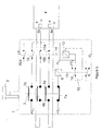
- Figure 1 is a circuit diagram of a safety switch which embodies the invention, an actuator being inserted in a body of the safety switch;
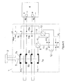
- Figures 2 to 6 show schematically in stages the effect of removing the actuator from the body of the safety switch; and
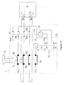
- Figures 7 to 10 show schematically in stages the effect of returning the actuator to the body of the safety switch.
- Figure 1 shows a safety switch which embodies the invention. The safety switch comprises a
body 1 into which anactuator 2 may be inserted. Theactuator 2 comprises afixing means 2a and a pair of prongs 2b, and is arranged to be inserted into and removed from thesafety switch 1.
Thesafety switch body 1 may be mounted on a door post of an enclosure (not shown) which contains dangerous electromechanical machinery (not shown). Theactuator 2 may be mounted on a door of the enclosure, and arranged such that when the door is closed the actuator is inserted into thesafety switch body 1. The safety switch is arranged to interrupt the supply of power to the machinery whenever theactuator 2 is removed from thesafety switch body 1. This means that whenever the door of the enclosure is opened, to allow access to the machinery, the machinery is automatically switched off. - In Figure 1 the
actuator 2 is inserted into thesafety switch body 1. Theactuator 2 is configured to engage with amoveable rod 3 of the safety switch, and push the moveable rod inwards (i.e. away from the nearest wall of the safety switch body 1). Themoveable rod 3 is resiliently biased, for example by one or more springs, to move outwards (i.e. towards the nearest wall of the safety switch body 1). - A
monitoring circuit 4 monitors the safety switch, via afirst monitoring port 4a and asecond monitoring port 4b. The safety switch is provided with two mechanically operatedoutput switches actuator 2 is removed from thesafety switch body 1. Thefirst monitoring port 4a of themonitoring circuit 4 is connected across the first mechanically operatedoutput switch 6a, and thesecond monitoring port 4b is connected across the second mechanically operatedoutput switch 6b. Themonitoring circuit 4 is arranged to monitor the interruption (or resumption) of the supply of power to the machinery. If themonitoring circuit 4 determines that a delay of more than 50 milliseconds has occurred between the interruption (or resumption) of the supply of power, as seen by thefirst monitoring port 4a and thesecond monitoring port 4b, then the monitoring circuit will shut down the machinery. A safety protocol is then followed, including checking whether thesafety switch body 1 is faulty, before the monitoring circuit is reset and the machinery is restarted. - It will be appreciated that the
monitoring circuit 4 may be arranged to allow a longer or shorter time delay than 50 milliseconds. The term 'substantially simultaneously' will be used hereafter to indicate a time delay which is sufficiently short that it will not cause themonitoring circuit 4 to shut down the machinery. - The safety switch is arranged to ensure that if the
actuator 2 is removed from the safety switch body, open circuits will occur substantially simultaneously across themonitoring ports output switches - The mechanically operated
output switches moveable rod 3. When theactuator 2 is inserted into thesafety switch body 1, it pushes themovable rod 3 inwards, thereby holding the mechanically operatedoutput switches - A mechanically operated
synchronisation switch 7a and a mechanically operatedpower supply switch 7b, are both operated by therod 3. The mechanically operatedsynchronisation switch 7a is connected between a first positive voltage source +V1 and arelay 8 which is in turn connected to a first negative voltage source -V1. The mechanically operatedpower supply switch 7b is connected between a second positive voltage source +V2 and a relay operated switch which will be described further below. - The
relay 8 is provided with two relay operatedswitches relay 8 and relay operatedswitches dotted line 11, such that the relay operatedswitches relay 8 are magnetically coupled. For ease of reference thisrelay 8 will hereafter be referred to as thefirst relay 8. A first of the relay operatedswitches 9 is connected to a light (not shown) which is arranged to indicate the status of the safety switch. For ease of reference, this relay operatedswitch 9 will hereafter be referred to as the relay operatedindicator switch 9. The second relay operatedswitch 10 is connected between a third positive voltage source +V3 and a first plate of acapacitor 12 when the first relay is turned off. This relay operatedswitch 10 will be hereafter referred to as the relay operatedcapacitor switch 10. A second plate of thecapacitor 12 is connected to a second negative voltage source -V2. Thus, when thefirst relay 8 is turned off, thecapacitor 12 is charged. - Although voltage sources are individually referenced in this description, this is for ease of illustration and is not intended to imply that each voltage source provides a different voltage. Instead, each of the positive voltage sources +V1, +V2, +V3 provide the same positive voltage, and each of the negative voltage sources -V1, -V2 provide the same negative voltage.
- The safety switch further comprises a
second relay 13 which is connected via a solenoid generally indicated by dottedline 14 to four relay operatedswitches output switches power supply switch 16 andauxiliary switch 17. The relay operatedoutput switches first monitoring port 4a and thesecond monitoring port 4b respectively, and are in closed configurations when thesecond relay 13 is turned off. The relay operatedpower supply switch 16 is arranged to connect the second positive voltage supply +V2, via the mechanically operatedpower supply switch 7b to thesecond relay 13. However, the relay operatedpower supply switch 16 is in an open configuration when thesecond relay 13 is turned off. - The
second relay 13 is connected on one side to the relay operatedcapacitor switch 10 and the relay operatedpower supply switch 16, and on the other side to the second negative voltage source -V2. - The normal configuration of the safety switch, when the
actuator 2 is inserted in thesafety switch body 1, is as shown in Figure 1. Themoveable rod 3 is pushed inwards by theactuator 2. Themoveable rod 3 ensures that the mechanically operatedoutput switches power supply switch 7b is in a closed configuration, and that the mechanically operatedsynchronisation switch 7a is in an open configuration. Thefirst relay 8 and thesecond relay 13 are both turned off. Thus, there are closed circuits across themonitoring ports monitoring circuit 4 allows the electromechanical machinery to operate. Because thefirst relay 8 is turned off, the relay operatedcapacitor switch 10 is in an open configuration and connects thecapacitor 12 to the third positive voltage source +V3, thereby ensuring that the capacitor is fully charged. The light (not shown) connected to the relay operatedindicator switch 9 indicates that the door of the enclosure is closed. - When a user opens the door of the enclosure, the
actuator 2 is removed from the safety switch body 1 (the actuator is attached to the door of the enclosure). The action of removing theactuator 2 is shown schematically in stages in Figures 2 to 7. Referring first to Figure 2, theactuator 2 has been moved a short distance out of thehousing 2. This movement has, via themoveable rod 3, moved the mechanically operatedsynchronisation switch 7a to a closed configuration. The mechanically operatedswitches moveable rod 3 are arranged such that when theactuator 2 has moved by the short distance shown in Figure 2, the mechanically operatedoutput switches power supply switch 7b have not moved from their closed configurations. - The effect of the mechanically operated
synchronisation switch 7a moving to a closed configuration is to connect thefirst relay 8 to the first positive voltage source +V1. This turns thefirst relay 8 on, which in turn, via thesolenoid 11, actuates the relay operatedcapacitor switch 10 and the relay operatedindicator switch 9. When the relay operatedindicator switch 9 is moved to an open configuration, the light (not shown) connected to the relay operated indicator switch indicates that the door of the enclosure is open. - When the
first relay 8 is energised, the relay operatedcapacitor switch 10 is moved to a closed configuration, such that the positively charged plate of thecapacitor 12 is connected to thesecond relay 13. - Referring to Figure 3, the
second relay 13 is energised when it is connected to the positively charged plate of thecapacitor 12. When thesecond relay 13 is energised it moves the relay operatedoutput switches power supply switch 16 and theauxiliary switch 17 to closed configurations. Synchronised movement of theswitches solenoid 14. The switching on of thefirst relay 8 and thesecond relay 13 happens very quickly, typically in less than one hundredth of a second, with the effect that theactuator 2 does not move appreciably during operation of therelays relays switches actuator 2 has moved sufficiently to open the mechanically operatedswitch 6a. - The effect of opening the relay operated
output switches solenoid 14 is that themonitoring circuit 4 simultaneously sees open circuits across thefirst monitoring port 4a and thesecond monitoring port 4b. Because themonitoring circuit 4 perceives the open circuits simultaneously (or substantially simultaneously), it does not perceive there to be a fault in the operation of the safety switch body. - The effect of closing the relay operated
power supply switch 16 is to connect the second positive voltage source +V2 via the mechanically operatedpower supply switch 7b to thesecond relay 13. This has the effect of keeping thesecond relay 13 energised once thecapacitor 12 has discharged. - Figures 4 and 5 show how, as the
actuator 2 continues to be moved out of thesafety switch body 1, the mechanically operatedoutput switches output switches 6a moves to the open configuration before a second of the mechanically operatedoutput switches 6b, due to the configuration of the output switches. In the absence of the relay operatedoutput switches actuator 2 could cause a time delay between movement of the mechanically operatedoutput switches monitoring circuit 4 perceive a fault in the operation of the safety switch. The embodiment of the invention solves this problem. This is advantageous because it avoids the need for an engineer to check whether the safety switch is working correctly, which may be time consuming and expensive. - Referring to Figure 6, as the
actuator 2 is moved fully out of thesafety switch body 1, the mechanically operatedpower supply switch 7b moves to an open configuration. This has the effect that the second positive voltage source +V2 is no longer connected to thesecond relay 13. Thesecond relay 13 thus turns off, and moves the relay operatedoutput switches power supply switch 16 and theauxiliary switch 17 to open configurations. Themonitoring circuit 4 continues to perceive interrupted voltages across themonitoring ports output switches - Once the door of the enclosure has been opened, a user may access the machinery, for example to perform maintenance work. Once maintenance of the machinery has been completed, the door of the enclosure is closed. On closing the door of the enclosure, the
actuator 2 is reinserted into thehousing 2, thereby closing the mechanically operatedoutput switches actuator 2 being reinserted into thesafety switch body 1. - Referring to Figure 7, when the
actuator 2 is a small distance into thesafety switch body 1, themoveable rod 3 moves the mechanically operatedpower supply switch 7b to the closed configuration. This has no effect because the relay operatedpower supply switch 16 remains in an open configuration. - Referring to Figures 8 and 9, as the
actuator 2 is moved further into thesafety switch body 1, themoveable rod 3 moves the mechanically operatedoutput switches output switches monitoring ports monitoring circuit 4. - Referring to Figure 10, as the
actuator 2 moves to its fully inserted position in thesafety switch body 1, themoveable rod 3 moves the mechanically operatedsynchronisation switch 7a to the open configuration. This disconnects the first positive voltage source from thefirst relay 8, thereby turning the first relay off. When thefirst relay 8 is turned off, it moves the relay operatedcapacitor switch 10 to an open configuration such that the third positive voltage source +V3 is connected to thecapacitor 12, thereby charging the capacitor. Thefirst relay 8 also moves the relay operatedindicator switch 9 to a closed configuration, so that the light (not shown) connected to the relay operatedindicator switch 9 indicates that the door of the enclosure is closed. - As has been explained above, the purpose of the
monitoring circuit 4 is to check that thesafety switch body 1 is operating correctly. In particular, the monitoring circuit is intended to be able to detect whether one of the mechanically operatedoutput switches output switches output switches monitoring circuit 4 will see substantially simultaneous open circuits across themonitoring ports actuator 2 is removed from thesafety switch body 1. Whilst this is advantageous in the case where the safety switch is operating correctly but has been actuated slowly, it is necessary that themonitoring circuit 4 remains able to detect whether operation of the safety switch is faulty. - As shown in Figure 6, when the
actuator 2 is fully removed from thesafety switch body 1, the relay operatedoutput switches monitoring circuit 4 to detect whether one of the mechanically operatedoutput switches - As shown in Figure 8, the relay operated
output switches actuator 2 is re-inserted into thesafety switch body 1. This allows themonitoring circuit 4 to detect a fault if one of the mechanically operatedoutput switches - As described above in relation to Figure 2, when the
actuator 2 is removed from thesafety switch body 1, the mechanically operatedsynchronisation switch 7a is actuated before the other mechanically operated switches. An advantage of this arrangement is that if theactuator 2 were to move slightly outwards from thesafety switch body 1, for example due to vibration of electromechanical machinery, then substantially simultaneous open circuits would be seen across themonitoring ports monitoring circuit 4 to determine that a fault was present. This is advantageous because it avoids the requirement that an engineer checks that the safety switch is operating correctly. - Although the illustrated embodiment of the invention comprises two monitoring ports, it will be appreciated that the invention may be implemented for any number of monitoring ports. This may be achieved by adding additional mechanically operated output switches and associated relay operated output switches.
- Although the illustrated embodiment of the invention uses a
actuator 2 to actuate themoveable rod 3, it will be appreciated that other suitable means may be used to actuate themoveable rod 3. For example, a mechanical button may be used. Similarly, it is not necessary that actuation of themechanical switches mechanical switches - Although the illustrated embodiment of the invention uses individual electrical components, which may for example be mounted on a printed circuit board, it will be appreciated that the invention may alternatively be implemented in semiconductor as in integrated circuit.
Claims (10)
- A safety switch body having a plurality of outputs, each output comprising a mechanically operated output switch and an electrically operated output switch, the electrically operated output switches being connected to a mechanically operated synchronisation switch, wherein the mechanically operated output switches and synchronisation switch are connected to a mechanical mechanism arranged such that, during operation of the safety switch, the mechanically operated synchronisation switch is actuated before the mechanically operated output switches, thereby switching the electrically operated output switches before the mechanically operated output switches are actuated.
- A safety switch according to claim 1, wherein the electrically operated output switches are connected to the mechanically operated synchronisation switch by an electrical mechanism.
- A safety switch according to claim 2, wherein the electrical mechanism is a relay.
- A safety switch according to claim 3, wherein the mechanically operated synchronisation switch is connected to the relay via a second relay.
- A safety switch according to claim 3, further comprising a capacitor switched by the second relay between an electrical source and the first relay, the second relay being arranged such that the capacitor is connected to the electrical source until the mechanically operated synchronisation switch is actuated, whereupon the capacitor is connected to the first relay, thereby discharging the capacitor through the first relay to energise the first relay on.
- A safety switch according to claim 4 or claim 5, wherein the safety switch further comprises a relay operated power supply switch, the relay operated power supply switch being connected between an electrical source and the first relay, and being closed when the first relay is energised, thereby providing electrical power to the first relay.
- A safety switch according to claim 6, wherein a mechanically operated power supply switch is connected between the first relay and the electrical source, the mechanically operated power supply switch being connected to the mechanical actuator, the mechanical actuator being arranged such that during actuation the mechanically operated power supply switch is actuated after the mechanically operated output switches, thereby interrupting the electrical power provided to the first relay.
- A safety switch according to any preceding claim, wherein a monitoring circuit is provided, the monitoring circuit having a monitoring port connected across each output of the safety switch.
- A safety switch according to any preceding claim, wherein the mechanical actuator comprises a resiliently mounted moveable rod.
- A safety switch according to any preceding claim, wherein the mechanical actuator is arranged to be actuated by a removable key.
Applications Claiming Priority (1)
| Application Number | Priority Date | Filing Date | Title |
|---|---|---|---|
| GB0520515A GB0520515D0 (en) | 2005-10-08 | 2005-10-08 | Safety switch |
Publications (2)
| Publication Number | Publication Date |
|---|---|
| EP1772880A1 true EP1772880A1 (en) | 2007-04-11 |
| EP1772880B1 EP1772880B1 (en) | 2008-08-27 |
Family
ID=35430059
Family Applications (1)
| Application Number | Title | Priority Date | Filing Date |
|---|---|---|---|
| EP20060254894 Ceased EP1772880B1 (en) | 2005-10-08 | 2006-09-21 | Safety switch |
Country Status (3)
| Country | Link |
|---|---|
| EP (1) | EP1772880B1 (en) |
| DE (1) | DE602006002464D1 (en) |
| GB (1) | GB0520515D0 (en) |
Citations (2)
| Publication number | Priority date | Publication date | Assignee | Title |
|---|---|---|---|---|
| FR1384673A (en) * | 1962-11-07 | 1965-01-08 | Westinghouse Electric Corp | Medium voltage contactor and line switching device |
| DE3606458A1 (en) * | 1986-02-27 | 1987-09-03 | Siemens Ag | Electromechanical locking arrangement |
-
2005
- 2005-10-08 GB GB0520515A patent/GB0520515D0/en not_active Ceased
-
2006
- 2006-09-21 DE DE200660002464 patent/DE602006002464D1/en active Active
- 2006-09-21 EP EP20060254894 patent/EP1772880B1/en not_active Ceased
Patent Citations (2)
| Publication number | Priority date | Publication date | Assignee | Title |
|---|---|---|---|---|
| FR1384673A (en) * | 1962-11-07 | 1965-01-08 | Westinghouse Electric Corp | Medium voltage contactor and line switching device |
| DE3606458A1 (en) * | 1986-02-27 | 1987-09-03 | Siemens Ag | Electromechanical locking arrangement |
Also Published As
| Publication number | Publication date |
|---|---|
| EP1772880B1 (en) | 2008-08-27 |
| GB0520515D0 (en) | 2005-11-16 |
| DE602006002464D1 (en) | 2008-10-09 |
Similar Documents
| Publication | Publication Date | Title |
|---|---|---|
| KR100887448B1 (en) | Method and device for securely operating a switching device | |
| JP4490616B2 (en) | Safety switching device for electrical load connection and safety disconnection | |
| KR102506084B1 (en) | Vacuum circuit breaker equipped with a function of realtime monitoring and the monitoring method | |
| KR20180110532A (en) | Electric interlock circuit for circuit breaker | |
| EP1876616B1 (en) | Reset device for limit switch and limit switch incorporating such device | |
| WO2018020364A1 (en) | Voltage loss protection circuit and starting cabinet | |
| CN203192640U (en) | Interlocking device of high-voltage stationary cabinet | |
| CN106158523B (en) | A circuit breaker fault tripping indicating mechanism | |
| EP1772880B1 (en) | Safety switch | |
| JP2010015987A (en) | Switching device equipped with remover | |
| CN120376366A (en) | Magnetic flux release, isolating switch and power supply system | |
| JP4824897B2 (en) | Safety switching device | |
| US9805896B2 (en) | Mechanically operated switching device and related switchgear having a movable member for operating the switching device | |
| US20150238059A1 (en) | Power supply arrangement for a suction device and suction device | |
| SU1105956A1 (en) | Automatic starter | |
| CN215933404U (en) | Travel switch | |
| CN101208764A (en) | Modular switchgear | |
| EP4528767A1 (en) | Solid state circuit breaker | |
| JP2008226604A (en) | Push-button switch | |
| US10199181B2 (en) | Holding device for receiving switching elements for a command and alert device | |
| CN117672767A (en) | Relay devices and safety switching devices with at least one relay device | |
| EP3863133A1 (en) | Improved safety mechanism for an electrical system with an electrical switchgear and a slide-in unit | |
| KR19990086873A (en) | Emergency switch | |
| CN106710911A (en) | Drawer-type automatic change-over switch | |
| CN205211135U (en) | System with a signaling device and a signaling device evaluation device arranged decentralized with respect to the signaling device |
Legal Events
| Date | Code | Title | Description |
|---|---|---|---|
| PUAI | Public reference made under article 153(3) epc to a published international application that has entered the european phase |
Free format text: ORIGINAL CODE: 0009012 |
|
| AK | Designated contracting states |
Kind code of ref document: A1 Designated state(s): AT BE BG CH CY CZ DE DK EE ES FI FR GB GR HU IE IS IT LI LT LU LV MC NL PL PT RO SE SI SK TR |
|
| AX | Request for extension of the european patent |
Extension state: AL BA HR MK YU |
|
| 17P | Request for examination filed |
Effective date: 20070828 |
|
| AKX | Designation fees paid |
Designated state(s): DE FR GB IT |
|
| GRAP | Despatch of communication of intention to grant a patent |
Free format text: ORIGINAL CODE: EPIDOSNIGR1 |
|
| GRAS | Grant fee paid |
Free format text: ORIGINAL CODE: EPIDOSNIGR3 |
|
| GRAA | (expected) grant |
Free format text: ORIGINAL CODE: 0009210 |
|
| AK | Designated contracting states |
Kind code of ref document: B1 Designated state(s): DE FR GB IT |
|
| REG | Reference to a national code |
Ref country code: GB Ref legal event code: FG4D |
|
| REF | Corresponds to: |
Ref document number: 602006002464 Country of ref document: DE Date of ref document: 20081009 Kind code of ref document: P |
|
| RAP2 | Party data changed (patent owner data changed or rights of a patent transferred) |
Owner name: ROCKWELL AUTOMATION LIMITED |
|
| PLBE | No opposition filed within time limit |
Free format text: ORIGINAL CODE: 0009261 |
|
| STAA | Information on the status of an ep patent application or granted ep patent |
Free format text: STATUS: NO OPPOSITION FILED WITHIN TIME LIMIT |
|
| 26N | No opposition filed |
Effective date: 20090528 |
|
| PG25 | Lapsed in a contracting state [announced via postgrant information from national office to epo] |
Ref country code: IT Free format text: LAPSE BECAUSE OF FAILURE TO SUBMIT A TRANSLATION OF THE DESCRIPTION OR TO PAY THE FEE WITHIN THE PRESCRIBED TIME-LIMIT Effective date: 20080827 |
|
| REG | Reference to a national code |
Ref country code: FR Ref legal event code: PLFP Year of fee payment: 10 |
|
| REG | Reference to a national code |
Ref country code: FR Ref legal event code: PLFP Year of fee payment: 11 |
|
| REG | Reference to a national code |
Ref country code: FR Ref legal event code: PLFP Year of fee payment: 12 |
|
| REG | Reference to a national code |
Ref country code: FR Ref legal event code: PLFP Year of fee payment: 13 |
|
| PGFP | Annual fee paid to national office [announced via postgrant information from national office to epo] |
Ref country code: GB Payment date: 20200819 Year of fee payment: 15 Ref country code: FR Payment date: 20200819 Year of fee payment: 15 Ref country code: DE Payment date: 20200819 Year of fee payment: 15 |
|
| REG | Reference to a national code |
Ref country code: DE Ref legal event code: R119 Ref document number: 602006002464 Country of ref document: DE |
|
| GBPC | Gb: european patent ceased through non-payment of renewal fee |
Effective date: 20210921 |
|
| PG25 | Lapsed in a contracting state [announced via postgrant information from national office to epo] |
Ref country code: GB Free format text: LAPSE BECAUSE OF NON-PAYMENT OF DUE FEES Effective date: 20210921 Ref country code: FR Free format text: LAPSE BECAUSE OF NON-PAYMENT OF DUE FEES Effective date: 20210930 Ref country code: DE Free format text: LAPSE BECAUSE OF NON-PAYMENT OF DUE FEES Effective date: 20220401 |