EP1772766B1 - Illumination system and projection display apparatus - Google Patents
Illumination system and projection display apparatus Download PDFInfo
- Publication number
- EP1772766B1 EP1772766B1 EP06022597A EP06022597A EP1772766B1 EP 1772766 B1 EP1772766 B1 EP 1772766B1 EP 06022597 A EP06022597 A EP 06022597A EP 06022597 A EP06022597 A EP 06022597A EP 1772766 B1 EP1772766 B1 EP 1772766B1
- Authority
- EP
- European Patent Office
- Prior art keywords
- light
- lens
- lens array
- illumination
- illumination system
- Prior art date
- Legal status (The legal status is an assumption and is not a legal conclusion. Google has not performed a legal analysis and makes no representation as to the accuracy of the status listed.)
- Expired - Lifetime
Links
Images


Classifications
-
- G—PHYSICS
- G02—OPTICS
- G02B—OPTICAL ELEMENTS, SYSTEMS OR APPARATUS
- G02B27/00—Optical systems or apparatus not provided for by any of the groups G02B1/00 - G02B26/00, G02B30/00
- G02B27/09—Beam shaping, e.g. changing the cross-sectional area, not otherwise provided for
- G02B27/0938—Using specific optical elements
- G02B27/095—Refractive optical elements
- G02B27/0955—Lenses
- G02B27/0966—Cylindrical lenses
-
- G—PHYSICS
- G02—OPTICS
- G02B—OPTICAL ELEMENTS, SYSTEMS OR APPARATUS
- G02B27/00—Optical systems or apparatus not provided for by any of the groups G02B1/00 - G02B26/00, G02B30/00
- G02B27/09—Beam shaping, e.g. changing the cross-sectional area, not otherwise provided for
- G02B27/0905—Dividing and/or superposing multiple light beams
-
- G—PHYSICS
- G03—PHOTOGRAPHY; CINEMATOGRAPHY; ANALOGOUS TECHNIQUES USING WAVES OTHER THAN OPTICAL WAVES; ELECTROGRAPHY; HOLOGRAPHY
- G03B—APPARATUS OR ARRANGEMENTS FOR TAKING PHOTOGRAPHS OR FOR PROJECTING OR VIEWING THEM; APPARATUS OR ARRANGEMENTS EMPLOYING ANALOGOUS TECHNIQUES USING WAVES OTHER THAN OPTICAL WAVES; ACCESSORIES THEREFOR
- G03B21/00—Projectors or projection-type viewers; Accessories therefor
- G03B21/14—Details
- G03B21/20—Lamp housings
- G03B21/2073—Polarisers in the lamp house
-
- G—PHYSICS
- G03—PHOTOGRAPHY; CINEMATOGRAPHY; ANALOGOUS TECHNIQUES USING WAVES OTHER THAN OPTICAL WAVES; ELECTROGRAPHY; HOLOGRAPHY
- G03B—APPARATUS OR ARRANGEMENTS FOR TAKING PHOTOGRAPHS OR FOR PROJECTING OR VIEWING THEM; APPARATUS OR ARRANGEMENTS EMPLOYING ANALOGOUS TECHNIQUES USING WAVES OTHER THAN OPTICAL WAVES; ACCESSORIES THEREFOR
- G03B21/00—Projectors or projection-type viewers; Accessories therefor
- G03B21/14—Details
- G03B21/20—Lamp housings
- G03B21/208—Homogenising, shaping of the illumination light
-
- G—PHYSICS
- G03—PHOTOGRAPHY; CINEMATOGRAPHY; ANALOGOUS TECHNIQUES USING WAVES OTHER THAN OPTICAL WAVES; ELECTROGRAPHY; HOLOGRAPHY
- G03B—APPARATUS OR ARRANGEMENTS FOR TAKING PHOTOGRAPHS OR FOR PROJECTING OR VIEWING THEM; APPARATUS OR ARRANGEMENTS EMPLOYING ANALOGOUS TECHNIQUES USING WAVES OTHER THAN OPTICAL WAVES; ACCESSORIES THEREFOR
- G03B33/00—Colour photography, other than mere exposure or projection of a colour film
- G03B33/10—Simultaneous recording or projection
- G03B33/12—Simultaneous recording or projection using beam-splitting or beam-combining systems, e.g. dichroic mirrors
-
- H—ELECTRICITY
- H04—ELECTRIC COMMUNICATION TECHNIQUE
- H04N—PICTORIAL COMMUNICATION, e.g. TELEVISION
- H04N5/00—Details of television systems
- H04N5/74—Projection arrangements for image reproduction, e.g. using eidophor
-
- H—ELECTRICITY
- H04—ELECTRIC COMMUNICATION TECHNIQUE
- H04N—PICTORIAL COMMUNICATION, e.g. TELEVISION
- H04N9/00—Details of colour television systems
- H04N9/12—Picture reproducers
- H04N9/31—Projection devices for colour picture display, e.g. using electronic spatial light modulators [ESLM]
- H04N9/3102—Projection devices for colour picture display, e.g. using electronic spatial light modulators [ESLM] using two-dimensional electronic spatial light modulators
- H04N9/3105—Projection devices for colour picture display, e.g. using electronic spatial light modulators [ESLM] using two-dimensional electronic spatial light modulators for displaying all colours simultaneously, e.g. by using two or more electronic spatial light modulators
-
- H—ELECTRICITY
- H04—ELECTRIC COMMUNICATION TECHNIQUE
- H04N—PICTORIAL COMMUNICATION, e.g. TELEVISION
- H04N9/00—Details of colour television systems
- H04N9/12—Picture reproducers
- H04N9/31—Projection devices for colour picture display, e.g. using electronic spatial light modulators [ESLM]
- H04N9/3141—Constructional details thereof
- H04N9/315—Modulator illumination systems
- H04N9/3152—Modulator illumination systems for shaping the light beam
-
- G—PHYSICS
- G02—OPTICS
- G02F—OPTICAL DEVICES OR ARRANGEMENTS FOR THE CONTROL OF LIGHT BY MODIFICATION OF THE OPTICAL PROPERTIES OF THE MEDIA OF THE ELEMENTS INVOLVED THEREIN; NON-LINEAR OPTICS; FREQUENCY-CHANGING OF LIGHT; OPTICAL LOGIC ELEMENTS; OPTICAL ANALOGUE/DIGITAL CONVERTERS
- G02F1/00—Devices or arrangements for the control of the intensity, colour, phase, polarisation or direction of light arriving from an independent light source, e.g. switching, gating or modulating; Non-linear optics
- G02F1/01—Devices or arrangements for the control of the intensity, colour, phase, polarisation or direction of light arriving from an independent light source, e.g. switching, gating or modulating; Non-linear optics for the control of the intensity, phase, polarisation or colour
- G02F1/13—Devices or arrangements for the control of the intensity, colour, phase, polarisation or direction of light arriving from an independent light source, e.g. switching, gating or modulating; Non-linear optics for the control of the intensity, phase, polarisation or colour based on liquid crystals, e.g. single liquid crystal display cells
- G02F1/133—Constructional arrangements; Operation of liquid crystal cells; Circuit arrangements
- G02F1/1333—Constructional arrangements; Manufacturing methods
- G02F1/1335—Structural association of cells with optical devices, e.g. polarisers or reflectors
- G02F1/1336—Illuminating devices
Definitions
- the present invention relates to an illumination system that divides a light flux emitted from a light source into a plurality of partial light fluxes and causes the plurality of partial light fluxes to be superimposed on an identical illumination area.
- the present invention also pertains to a projection display apparatus that produces substantially uniform, bright projected images using such an illumination system.
- a projection display apparatus uses a light modulator, or 'light valve', to modulate illumination light, illuminating the light modulator, responsive to image information, and projects the modulated light flux on a screen to display an image.
- a typical example of the light modulator is a liquid-crystal panel. It is naturally desirable that the image displayed by the projection display apparatus is substantially uniform and bright.
- the illumination light emitted from an illumination device (illumination system) incorporated in the projection display apparatus should have a high utilization efficiency of light.
- One proposed technique to enhance the utilization efficiency of the illumination light disposes a plurality of micro lenses corresponding to the respective pixels of the liquid-crystal panel on the light-entering side of the liquid-crystal panel.
- Figs. 15(A) and 15(B) show light fluxes entering a liquid-crystal panel in the case where micro lenses are disposed on the light-entering side of the liquid-crystal panel. More concretely Figs. 15(A) and 15(B) show the cross section of a liquid-crystal panel 1000 and a micro lens array 1100 including a plurality of micro lenses 1110.
- the liquid-crystal panel 1000 includes liquid-crystal layers 1010 that are surrounded by light shielding layers 1020, which are referred to as the black matrixes', in a lattice configuration.
- the micro lens array 1100 is disposed on the light-entering side of the liquid-crystal panel 1000 in such a manner that the center of one liquid-crystal layer 1010 corresponding to each pixel of the liquid-crystal panel 1000 substantially coincides with the optical axis of one micro lens 1110.
- the light flux which enters the micro lens 1110 substantially in parallel with the optical axis of the micro lens 1110, is condensed by the micro lens 1110 to pass through the liquid-crystal layer 1010.
- This arrangement ensures the utilization of such light fluxes that wpuld be shielded by the light shielding layers 1020 in the structure without the micro lenses 1110.
- the micro lenses accordingly work to enhance the utilization efficiency of light.
- the micro lens 1110 also condenses the light flux that enters the micro lens 1110 obliquely to the optical axis of the micro lens 1110 as shown in Fig. 15(B) . Part of this light flux, however, does not pass through the liquid-crystal layer 1010 but is shielded by the light shielding layer 1020. In this case, the use of the micro lenses worsens the utilization efficiency of light. This phenomenon is more significant in the case of the greater angle of the light flux to the optical axis (that is, the incident angle).
- the smaller incident angle of light into the liquid-crystal panel relieves the above problem and improves the utilization efficiency of light.
- the smaller incident angle of light into an optical element other than the liquid-crystal panel for example, a projection lens for causing the modulated light flux emitted from the liquid-crystal panel to be projected on a screen
- One possible method of decreasing the incident angle of light into an illumination area is to lengthen the optical path between a light source and the illumination area (especially the optical path between the light source and an optical element immediately before the illumination area). This method, however, undesirably increases the size of the whole illumination system.
- a light flux emitted from the light source is divided into a plurality of partial light fluxes, and the plurality of partial light fluxes are superimposed on the illumination area. It is accordingly difficult to decrease the incident angle of light into the illumination area without significantly lengthening the optical path in the illumination system including the optical integrator system.
- the object of the present invention is to solve the above problem arising in the prior art and provide a technique that decreases the incident angle of a light flux into an illumination area without significantly lengthening an optical path between a light source and the illumination area in an illumination system including an optical integrator system.
- the present invention is directed to an illumination system that divides a light flux emitted from a light source into a plurality of partial light fluxes and causes the plurality of partial light fluxes to be substantially superimposed on an illumination area, so as to enable a light-entering face of a specific optical apparatus to be illuminated as the illumination area as defined in claim 1.
- x-axis direction the lateral direction
- y-axis direction the vertical direction
- z-axis direction the direction in parallel to the optical axis
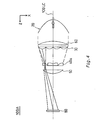
- Fig. 1 is a plan view schematically illustrating a main part of an illumination system in a first comparative example.
- This illumination system 100 includes a light source 20 that emits a substantially parallel light flux, a first lens array 30, a condenser lens 60, a diverging lens 70, a second lens array 40, and a superimposing lens 50.
- the respective constituents are arranged in this sequence along a system optical axis 100LC.
- the illumination system 100 is an optical integrator system that enables an illumination area 80 to be illuminated in a substantially uniform manner.
- the light source 20 includes a light source lamp 22, which functions as a radiant light source for emitting radiant rays, and a concave mirror 24, which changes the radiant rays emitted from the light source lamp 22 to a substantially parallel light flux.
- a paraboloidal mirror is preferably used for the concave mirror 24.
- the functions of the optical integrator system are actualized by the first lens array 30, the second lens array 40, and the superimposing lens 50 among these constituents.
- the first lens array 30 and the second lens array 40 have the function of the light flux dividing section.
- the first lens array 30 divides a ray of light emitted from the light source 20 into a plurality of partial light fluxes and condenses each partial light flux in the vicinity of the second lens array 40.
- the second lens array 40 causes the illumination area 80 to be illuminated with rays of light emitted from respective small lenses 31 included in the first lens array 30.
- the superimposing lens 50 causes the plurality of partial light fluxes having the center axes in parallel to the system optical axis to be superimposed on the illumination area 80.
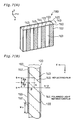
- Fig. 2 is a perspective view illustrating the appearance of the first lens array 30.
- the first lens array 30 consists of the small lenses 31 that have the contour of a substantially rectangular shape and are arranged in an M ⁇ N matrix.
- the second lens array 40 (see Fig. 1 ) also consists of small lenses, which are arranged in an M ⁇ N matrix corresponding to the small lenses 31 of the first lens array 30.
- the second lens array 40 is smaller than the first lens array 30 in size as described later.
- the small lenses 31 included in the first lens array 30 divide the light flux emitted from the light source 20 (see Fig. 1 ) into a plurality of (that is, M ⁇ N) partial light fluxes and cause the respective partial light fluxes to be condensed in the vicinity of the second lens array 40.
- the outer shape of each small lens 31 seen from the z direction is typically set to be substantially similar to the shape of a specific area that is actually illuminated with rays of light in the illumination area 80.
- the illumination area is a liquid-crystal panel and an image display area has an aspect ratio (that is, a ratio of a lateral dimension to a vertical dimension) of 4 to 3
- the small lenses 30 have the aspect ratio of 4 to 3.
- the condenser lens 60 and the diverging lens 70 which are interposed between the first lens array 30 and the second lens array 40, constitute an afocal optical system that changes an incident light flux having a specific width to an emitting light flux having a width narrower than the specific width. These lenses 60 and 70 correspond to the light flux contraction section. Since , the condenser lens 60 and the diverging lens 70 constitute the afocal optical system, the angle of the emitting light flux from the diverging lens 70 is identical with the angle of the incident light flux into the condenser lens 60, while only the width of the light flux is contracted.
- Each partial light flux SL emitted from the diverging lens 70 is transmitted through the second lens array 40 and irradiates the illumination area 80 by section of the superimposing lens 50.
- the partial light flux SL that is transmitted through an outer-most small lens 41 included in the second lens array 40 has its central optical path at an incident angle of ⁇ 1, when irradiating the illumination area 80.
- the broken lines of Fig. 1 represent a second lens array 40' and a superimposing lens 50', which would be used in the absence of the afocal optical system, and also the optical path of a partial light flux SL' transmitted through the second lens array 40' and the superimposing lens 50'.
- the second lens array 40' has the same size as that of the first lens array 30.
- the second lens array 40' and the superimposing lens 50' are a little shifted in the z-axis direction in Fig. 1 for the clarity of illustration, they would be actually located at the same positions in the z-axis direction as those of the second lens array 40 and the superimposing lens 50.
- the partial light flux SL' emitted from the outer-most small lens 31 included in the first lens array 30 has its central optical path at an incident angle of ⁇ 2, while irradiating the illumination area 80.
- the smaller incident angle into the micro lenses improves the utilization efficiency of light.
- a typical technique adopted to decrease the incident angle of the light flux into the illumination area in the illumination system is to increase the distance between the illumination system and the illumination area. This technique, however, undesirably makes the whole system bulky. The longer optical path of the illumination system leads to a significant loss of light.
- the arrangement of this example utilizes the afocal optical system, which includes the condenser lens 60 and the diverging lens 70, to contract the total width of the light flux as a whole.
- the incident angle ⁇ 1 is accordingly smaller than the incident angle ⁇ 2.
- the use of the optical elements that cause the rays of light to enter the illumination area 80 improves the efficiency of light that effectively irradiates the illumination area 80 without making the whole system undesirably bulky, compared with the prior art illumination system.
- the light flux emitted from the afocal optical system has the contracted total width as a whole, and the optical elements located after the afocal optical system can thus be reduced in size.
- Figs. 3 (A-1), 3(A-2), 3(B-1) and 3(B-2) show other possible configurations of the first lens array 30 and the condenser lens 60 and other possible configurations of the second lens array 40 and the diverging lens 70 in the first example.
- the first lens array 30 and the condenser lens 60 are arranged separately in the example of Fig. 1 , the first lens array 30 and the condenser lens 60 may be optically integrated.
- the first lens array 30 and the condenser lens 60 which are manufactured as independent optical elements, may be bonded to each other via an adhesive to be optically integrated.
- One integral optical element having both the functions of the first lens array 30 and the condenser lens 60 may alternatively be formed.
- the first lens array 30 and the condenser lens 60 may be formed integrally as a decentered lens array 30a having both the functions of the first lens array 30 and the condenser lens 60 as shown in Fig. 3 (A-2).
- the arrangement of optically integrating the first lens array 30 and the condenser lens 60 as shown in Figs. 3 (A-1) and 3(A-2) effectively reduces the loss of light occurring on the interfaces of the respective optical elements and further enhances the utilization efficiency of light.
- the positional relationship between the first lens array 30 and the condenser lens 60 and the orientations of these lenses 30 and 60 may be reversed from those shown in Fig. 1 and Figs. 3 (A-1) and 3(A-2).
- the second lens array 40 and the diverging lens 70 which are arranged separately in the example of Fig. 1 , may be integrated optically.
- the second lens array 40 and the diverging lens 70 which are manufactured as independent optical elements, may be bonded to each other via an adhesive to be optically integrated.
- One integral optical element having both the functions of the second lens array 40 and the diverging lens 70 may alternatively be formed.
- the second lens array 40 and the diverging lens 70 may be formed integrally as a decentered lens array 40a having both the functions of the second lens array 40 and the diverging lens 70 as shown in Fig. 3 (B-2).
- the arrangement of optically integrating the second lens array 40 and the diverging lens 70 as shown in Figs. 3 (B-1) and 3(B-2) effectively reduces the loss of light occurring on the interfaces of the respective optical elements and further enhances the utilization efficiency of light.
- the positional relationship between the second lens array 40 and the diverging lens 70 and the orientations of these lenses 40 and 70 may be reversed from those shown in Fig. 1 and Figs. 3 (B-1) and 3(B-2).
- Fig. 4 schematically illustrates a possible modification of the illumination system of the first example.
- the condenser lens 60 and the first lens array 30 are arranged in the reverse sequence to that in the illumination system 100 (see Fig. 1 ), and the orientations of the convex faces of these lenses 30 and 60 are reverse to those in the illumination system 100.
- the second lens array 40 and the diverging lens 70 are replaced by the decentered lens array 40a, and the convex face of the decentered lens array 40a is directed to the light-entering side.
- the first lens array 30 and the condenser lens 60 may be bonded to each other via an adhesive as shown in Fig. 3 (A-1) or alternatively may be formed integrally.
- the illumination system 100A can decrease the incident angle into the illumination area without significantly lengthening the optical path between the light source and the illumination area. This arrangement improves the efficiency of light that effectively irradiates the illumination area.
- the condenser lens 60 changes the ray of light emitted from the light source 20 to a condensed ray of light (shown by the broken line in Fig. 4 ), which can enter the decentered lens array 40a.
- the first lens array 30 divides the condensed ray of light emitted from the condenser lens 60 into a plurality of partial light fluxes.
- This arrangement advantageously shortens the distance between the first lens array 30 and the decentered lens array 40a, compared with the distance between the first lens array 30 and the second lens array 40 in the first example.
- This arrangement also favorably improves the efficiency of light that is emitted from the light source 20 and enters the decentered lens array 40a, compared with the efficiency of light that is emitted from the light source 20 and enters the second lens array 40 in the illumination system 100.
- the condenser lens 60 and the diverging lens 70 constitute the afocal optical system.
- other optical elements may be used to constitute an afocal optical system.
- Fig. 5 shows another possible configuration of the afocal optical system.
- the afocal optical system includes a convex lens 60' having a relatively long focal length and another convex lens 70' having a relatively short focal length.
- the illumination system 100 of the first example shown in Fig. 1 may be constructed as a polarized light illumination system that utilizes only one type of polarized light fluxes.
- Fig. 6 is a plan view schematically illustrating a main part of a polarized light illumination system, which replaces the illumination system 100, in a second example.
- the illumination system 200 of the second example has a similar structure to that of the illumination system 100 shown in Fig. 1 .
- the difference from the illumination system 100 is that a polarized light generator 180 is located between the second lens array 40 and the superimposing lens 50.
- a polarized light generator 180 is located between the second lens array 40 and the superimposing lens 50.
- the light flux emitted from the light source 20 is divided by the first lens array 30 into a plurality of partial light fluxes, which are contracted in total width by the condenser lens 60 and the diverging lens 70 and eventually emitted from the second lens array 40.
- the plurality of partial light fluxes, which are emitted from the second lens array 40 and have random polarizing directions, are converted into substantially one type of polarized light fluxes, which have a substantially identical polarizing direction, by the polarized light generator 180 as described later.
- the plurality of partial light fluxes having the substantially identical polarizing direction are superimposed on the illumination area 80 by section of the superimposing lens 50.
- the arrangement of the illumination system 200 preferably decreases the incident angle of the illumination light that irradiates the illumination area 80.
- the light source 20, the first lens array 30, the condenser lens 60, the diverging lens 70, and the second lens array 40 are arranged in such a manner that an optical axis 20LC thereof is shifted in parallel from a system optical axis 200LC in the x-axis direction by a fixed distance Dp.
- the fixed distance Dp will be discussed later.
- Figs. 7(A) and 7(B) show a possible configuration of the polarized light generator 180.
- Fig. 7(A) is a perspective view of the polarized light generator 180.
- the polarized light generator 180 includes a shading plate 120, a polarization beam splitter array 140, and a selective retardation plate 160.
- the polarization beam splitter array 140 includes a plurality of parallelepiped transparent plate members 143 that are successively bonded together. Polarized light separation film 144 and reflecting films 145 are alternately formed on the interfaces of the transparent plate members 143.
- the polarization beam splitter array 140 is manufactured by bonding a plurality of sheet glasses with the polarized light splitting films and the reflecting films formed thereon and cutting the sheet glass laminate obliquely at a specific angle, so that the polarized light splitting films 144 and the reflecting films 145 are arranged alternately.
- the polarized light separation film 144 is composed of a dielectric multi-layered film
- the reflecting film 145 is composed of a dielectric multi-layered film or an aluminum film.
- the shading plate 120 includes a plurality of shading faces 122 and a plurality of aperture faces 123 that are arranged in stripe.
- the light flux entering the shading face 122 is blocked by the shading plate 120, whereas the light flux entering the aperture face 123 passes through the shading plate 120.
- the shading plate 120 accordingly has the function of regulating the transmission of light fluxes according to the positions on the shading plate 120.
- the arrangement of the shading faces 122 and the aperture faces 123 is set to cause the partial light fluxes emitted from the second lens array 40 to enter only the polarized light splitting films 144 in the polarization beam splitter array 140 and not to enter the reflecting films 145.
- the arrangement causes the center of each aperture face 123 in the shading plate 120 to be substantially coincident with the center of a corresponding polarized light separation film 144 in the polarization beam splitter array 140.
- the lateral opening width (the opening width in the x-axis direction) of the aperture face 123 is set to be substantially identical with a width Wp of the polarized light separation film 144 in the x-axis direction.
- the shading plate 120 include a transparent plate-like body (for example, a glass plate) partially coated with a light shielding film (such as a chromium film, an aluminum film or a dielectric multi-layered film) and a light shielding material, such as an aluminum plate, with openings formed therein.
- a light shielding film such as a chromium film, an aluminum film or a dielectric multi-layered film
- a light shielding material such as an aluminum plate
- Fig. 7(B) shows the functions of the polarized light generator.
- the principal ray (the central optical path) of the light fluxes emitted from the second lens array 40 passes through the aperture face 123 of the shading plate 120 substantially in parallel to the system optical axis 200LC and is divided into an s-polarized light component and a p-polarized light component by the polarized light separation film 144.
- the p-polarized light component is transmitted through the polarized light separation film 144, whereas the s-polarized light component is reflected from the polarized light separation film 144 and further from the reflecting film 145 and is emitted substantially in parallel to the p-polarized light component, which has passed through the polarized light separation film 144.
- the selective retardation plate 160 has ⁇ /2 retardation layers 162 that are formed on the emitting part of the light components transmitted through the polarized light splitting films 144.
- the selective retardation plate 160 also has opening layers 163 that are formed in positions without the ⁇ /2 retardation layers, and more precisely, on the part emitting the light components reflected from the reflecting films 145.
- the p-polarized light component transmitted through the polarized light separation film 144 is converted into an s-polarized light component and output by the ⁇ /2 retardation layer 146.
- the light fluxes that enter the polarized light generator 180 and have the random polarizing directions are mostly converted into s-polarized light components to be output.
- One possible modification may form the ⁇ /2 retardation layers 162 in the selective retardation plate 160 only on the part emitting the light components reflected from the reflecting films 145, in order to cause the light fluxes to be mostly converted into p-polarized light components to be output.
- the center of the two s-polarized light components (the middle of the two s-polarized light components) emitted from the polarized light generator 180 is shifted in the x-axis direction from the center of the light fluxes of random polarizing directions that have entered the polarized light generator 180.
- the amount of shift is equal to half the width Wp of the ⁇ /2 retardation layer 162 (that is, the width of the polarized light separation film 144 in the x-axis direction).
- the optical axis 20LC of the light source 20 is accordingly shifted from the system optical axis 200LC after the polarized light generator 180 by the distance Dp equal to Wp/2.
- the functions of the illumination system 200 of the second example may be summarized as follows.
- the first lens array 30, the second lens array 40, and the superimposing lens 50 constitute the optical integrator system.
- the plurality of partial light fluxes divided by the first lens array 30 are superimposed on the illumination area 80 by section of the superimposing lens 50.
- the condenser lens 60 and the diverging lens 70 constitute the afocal optical system that contracts the total width of the light flux entering the second lens array 40.
- the polarized light generator 180 changes the partial light fluxes of random polarizing directions to one type of polarized light fluxes having a substantially identical polarizing direction.
- the shading plate 120 is disposed on the light-entering side of the polarization beam splitter array 140, in order to cause the partial light fluxes to enter only the polarized light splitting films 144. There are thus substantially no partial light fluxes that enter the polarized light splitting films 144 via the reflecting films 145.
- the type of the polarized light fluxes emitted from the polarized light generator 180 is thus practically limited to one.
- the illumination area 80 is accordingly irradiated with practically one type of polarized light fluxes in a substantially uniform manner. In the event that the light flux emitted from the light source 20 has a good parallelism, the second lens array 40 and the shading plate 120 may be omitted from the configuration.
- the illumination system 200 of the second example can decrease the incident angle of the illumination light that irradiates the illumination area 80.
- the use of the optical elements that cause the rays of light to enter the illumination area 80 improves the efficiency of light without making the whole system undesirably bulky, compared with the prior art illumination system.
- the light flux emitted from the afocal optical system has the contracted total width as a whole, and the optical elements located after the afocal optical system can thus be reduced in size.
- the illumination system 200 of the second example further has the following effects, in addition to the above advantages.
- the polarized light generator 180 changes the light fluxes of random polarizing directions emitted from the light source 20 to one type of polarized light fluxes having a substantially identical polarizing direction, with which the illumination area 80 is irradiated in a substantially uniform manner.
- the loss of light hardly occurs in the process of generating the polarized light fluxes, so that almost all the light emitted from the light source is led to the illumination area 80. This results in the extremely high utilization efficiency of light.
- the shading plate 120 is included in the polarized light generator 180, the polarized light fluxes that irradiate the illumination area 80 are hardly mixed with other polarized light fluxes having a different polarizing direction.
- a polarizer conventionally located on the light-entering side of the modulation section may be omitted in some cases.
- the illumination system without the polarized light generator and the illumination system with the polarized light generator have similar configurations except the polarized light generator. This is also true in other example discussed below.
- the condenser lens 60 and the first lens array 30 may be optically integrated as shown in Figs. 3 (A-1) and 3(A-2).
- the diverging lens 70 and the second lens array 40 may be optically integrated as shown in Figs. 3 (B-1) and 3(B-2).
- all the optical elements between the diverging lens 70 and the superimposing lens 50 may be optically integrated.
- Fig. 8 is a plan view schematically illustrating a main part of another illumination system in a third example.
- This illumination system 300 includes a light source 320 that emits a substantially parallel light flux, a condenser lens 360, a diverging lens 370, a first lens array 330, a second lens array 340, a polarized light generator 380, and a superimposing lens 350. These constituents are arranged in this sequence along a system optical axis 300LC.
- the illumination system 300 is characterized by the arrangement that the condenser lens 360 and the diverging lens 370 constituting an afocal optical system are interposed between the light source 320 and the first lens array 330.
- the first lens array 330, the second lens array 340, the polarized light generator 380, and the superimposing lens 350 are arranged to have a width corresponding to the total width of the light flux contracted by the afocal optical system.
- the functions of these optical elements are identical with the first lens array 30, the second lens array 40, the polarized light generator 180, and the superimposing lens 50 discussed in the illumination systems 100 and 200 and are thus not specifically described here.
- the condenser lens 360 and the diverging lens 370 first contract the width of the substantially parallel light flux emitted from the light source 320. This arrangement reduces the size of the respective optical elements arranged after the afocal optical system (including the condenser lens 360 and the diverging lens 370), and decreases the incident angle of the illumination light that irradiates the illumination area 80.
- the diverging lens 370 may be arranged immediately after the first lens array 370.
- the diverging lens 370 and the first lens array 330 may be optically integrated.
- all the optical elements between the second lens array 340 and the superimposing lens 50 may be optically integrated.
- Fig. 9 is a plan view schematically illustrating a main part of still another illumination system in a fourth example.
- This illumination system 400 includes a light source 420 that emits a substantially parallel light flux, a first lens array 430, a second lens array 440, a polarized light generator 480, a superimposing lens 450, a condenser lens 460, and a diverging lens 470. These constituents are arranged in this sequence along a system optical axis 400LC.
- the illumination system 400 is characterized by the arrangement that the condenser lens 460 and the diverging lens 470 constituting an afocal optical system are disposed after the superimposing lens 450, that is, between the superimposing lens 450 and the illumination area 80.
- the first lens array 430, the second lens array 440, the polarized light generator 480, and the superimposing lens 450 are arranged before the afocal optical system and have the size corresponding to that of the light source 420.
- the functions of these optical elements are identical with the first lens array 30, the second lens array 40, the polarized light generator 180, and the superimposing lens 50 discussed in the illumination systems 100 and 200 and are thus not specifically described here.
- the function of the afocal optical system including the condenser lens 460 and the diverging lens 470 contracts the total width of the plurality of partial light fluxes emitted from the superimposing lens 450.
- the plurality of partial light fluxes emitted from the afocal optical system are only superimposed to irradiate the illumination area 80. This arrangement enables the total width of the light flux as a whole to be contracted as much as possible by the afocal optical system. Compared with the other examples discussed above, the arrangement of the fourth example can further decrease the incident angle of the illumination light.
- the condenser lens 460 and the superimposing lens 450 are illustrated as separate optical elements for the purpose of clarifying the functions of the afocal optical system in the fourth example, the condenser lens 460 and the superimposing lens 450 are optically integrated in general. Namely the condenser lens 470 and the superimposing lens 450 may be constructed as one condenser lens. Alternatively all the optical elements between the second lens array 440 and the condenser lens 460 may be integrated optically.
- Fig. 10 is a plan view schematically illustrating a main part of another illumination system in a fifth example.
- This illumination system 500 includes a light source 520 that emits a substantially parallel light flux, a first lens array 530, a second lens array 540, a polarized light generator 580, a condenser lens 560, a diverging lens 570, and a superimposing lens 550. These constituents are arranged in this sequence along a system optical axis 500LC.
- the illumination system 500 is characterized by the arrangement that the condenser lens 560 and the diverging lens 570 constituting an afocal optical system are disposed before the superimposing lens 550, that is, between the polarized light generator 580 and the superimposing lens 550.
- the first lens array 530, the second lens array 540, and the polarized light generator 580 are arranged before the afocal optical system and have the size corresponding to that of the light source 520.
- the functions of these optical elements are identical with the first lens array 30, the second lens array 40, and the polarized light generator 180 discussed in the illumination systems 100 and 200 and are thus not specifically described here.
- the function of the afocal optical system including the condenser lens 560 and the diverging lens 570 contracts the total width of the plurality of partial light fluxes emitted from the polarized light generator 580.
- the principal ray of the plurality of partial light fluxes emitted from the diverging lens 570 enters the superimposing lens 550 substantially in parallel to the system optical axis 500LC and is superimposed on the illumination area 80.
- the plurality of partial light fluxes emitted from the afocal optical system are only superimposed to irradiate the illumination area 80.
- the arrangement of the fifth example can further decrease the incident angle of the illumination light.
- the superimposing lens 550 and the diverging lens 570 in the fifth embodiment may be optically integrated.
- all the optical elements between the second lens array 540 and the condenser lens 560 may be integrated optically.
- Fig. 11 is a plan view schematically illustrating a main part of still another illumination system in a sixth example.
- This illumination system 600 includes a light source 620 that emits a substantially parallel light flux a first lens array 630, a condenser lens 660, a diverging lens 670, a second lens array 640, and a polarized light generator 680. These constituents are arranged in this sequence along a system optical axis 600LC.
- the illumination system 600 is characterized by the arrangement that the condenser lens 660 and the diverging lens 670 constituting an afocal optical system are interposed between the first lens array 630 and the second lens array 640 and that the superimposing lens is omitted.
- the respective optical elements arranged after the afocal optical system are designed to have the size corresponding to the width of the light flux contracted by the afocal optical system.
- the functions of the first lens array 630, the second lens array 640, and the polarized light generator 680 are identical with the first lens array 30, the second lens array 40, and the polarized light generator 180 discussed in the illumination systems 100 and 200 and are thus not specifically described here.
- the condenser lens 660 and the diverging lens 670 have the function of the afocal optical system.
- the condenser lens 660 causes the plurality of partial light fluxes divided by the first lens array 630 to be superimposed on the illumination area 80.
- the function of the afocal optical system including the condenser lens 660 and the diverging lens 670 contracts the total width of the plurality of partial light fluxes emitted from the first lens array 630.
- the superimposing function of the condenser lens 660 causes the plurality of partial light fluxes emitted from the diverging lens 670 to be superimposed on the illumination area 80 via the second lens array 640 and the polarized light generator 680.
- the arrangement of the sixth example decreases the incident angle of the illumination light that irradiates the illumination area 80. Since the total width of the light flux emitted from the afocal optical system is contracted, the optical elements arranged after the afocal optical system can be reduced in size.
- the use of the polarized light generator 680 changes the light fluxes of random polarizing directions to one type of polarized light fluxes having a substantially identical polarizing direction, with which the illumination area 80 is irradiated in a substantially uniform manner.
- the principal ray of each partial light flux is inclined to the system optical axis 600LC, so that the respective partial light fluxes entering the polarized light generator 680 are superimposed on the illumination area 80. It is, however, preferable that the incident light flux entering the polarized light generator 680 is in parallel to the optical axis for the higher generation efficiency of the polarized light fluxes.
- the omission of the superimposing lens is the advantage of the sixth embodiment, the loss of light arises in the process of generating the polarized light fluxes and may result in the lower utilization efficiency of light, compared with the other examples discussed above.
- the condenser lens 660 and the first lens array 630 may be integrated optically.
- the diverging lens 670 and the second lens array 640 may be integrated optically.
- all the optical elements between the diverging lens 670 and the polarized light generator 680 may be integrated optically
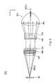
- Fig. 12 is a plan view schematically illustrating a main part of another illumination system in an embodiment according to the present invention.
- This illumination system 700 includes a light source 720, a first lens array 730, a diverging lens 770, a second lens array 740, a polarized light generator 780, and a superimposing lens 750. These constituents are arranged in this sequence along a system optical axis 700LC.
- the light source 720 includes a light source lamp 722, which functions as a radiant light source for emitting radiant rays, and a concave mirror 724, which reflects the radiant rays emitted from the light source lamp 722 and condenses the reflected rays of light at a predetermined position on a light source optical axis 720LC.
- a ellipsoidal mirror is preferably used for the concave mirror 724.
- the illumination system 700 is characterized by the arrangement that the concave mirror 724 of the light source 720 and the diverging lens 770 constitute an afocal optical system.
- the second lens array 740, the polarized light generator 780, and the superimposing lens 750 are designed to have the size corresponding to the width of the light flux contracted by the afocal optical system.
- the functions of the first lens array 730, the second lens array 740, the polarized light generator 780, and the superimposing lens 750 are identical with the first lens array 30, the second lens array 40, the polarized light generator 180, and the superimposing lens 50 discussed in the illumination systems 100 and 200 and are thus not specifically described here.
- the light flux emitted from the light source 720 is condensed and passes through the first lens array 730 to be divided into a plurality of partial light fluxes.
- the diverging lens 770 converts the principal rays of the plurality of partial light fluxes into the light fluxes substantially parallel to the system optical axis 700LC.
- the plurality of partial light fluxes accordingly have the contracted total width as a whole, enter the second lens array 740, and irradiate the illumination area 80 via the polarized light generator 780 and the superimposing lens 750. This arrangement ensures the size reduction of the respective optical elements arranged after the diverging lens 770, and decreases the incident angle of the illumination light that irradiates the illumination area 80.
- the diverging lens 770 and the second lens array 740 may be integrated optically Alternatively all the optical elements between the diverging lens 770 and the superimposing lens 750 may be integrated optically.
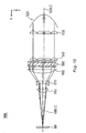
- Fig. 13 is a plan view schematically illustrating a main part of another illumination system in an seventh example.
- This illumination system 800 includes a light source 820, a diverging lens 870, a first lens array 830, a second lens array 840, a polarized light generator 880, and a superimposing lens 850. These constituents are arranged in this sequence along a system optical axis 800LC.
- the light source 820 includes a light source lamp 822, which functions as a radiant light source for emitting radiant rays, and a concave mirror 824, which reflects the radiant rays emitted from the light source lamp 822 and condenses the reflected rays of light at a predetermined position on a light source optical axis 820LC.
- the illumination system 800 is characterized by the arrangement that the concave mirror 824 of the light source 820 and the diverging lens 870 constitute an afocal optical system.
- the first lens array 830, the second lens array 840, the polarized light generator 880, and the superimposing lens 850 are designed to have the size corresponding to the width of the light flux contracted by the afocal optical system.
- the functions of these optical elements are identical with the first lens array 30, the second lens array 40, the polarized light generator 180, and the superimposing lens 50 discussed in the illumination systems 100 and 200 and are thus not specifically described here.
- the condensed light flux emitted from the light source 820 passes through the diverging lens 870 to be converted into a substantially parallel light flux having a contracted width.
- the substantially parallel light flux then enters the first lens array 830 and irradiates the illumination area 80 via the second lens array 840, the polarized light generator 880, and the superimposing lens 850.
- This arrangement ensures the size reduction of the respective optical elements arranged after the diverging lens 870, and decreases the incident angle of the illumination light that irradiates the illumination area 80.
- the diverging lens 870 and the first lens array 830 may be integrated optically.
- all the optical elements between the second lens array 840 and the superimposing lens 850 may be integrated optically.
- Fig. 14 is a plan view schematically illustrating a main part of a projection display apparatus using an illumination system.
- This projection display apparatus 900 includes an illumination system 200' that basically has the same structure as that of the illumination system 200 of the second example. The difference from the illumination system 200 is that a reflecting mirror 90 is disposed on the light-emitting side of the superimposing lens 50, in order to lead the light flux emitted from the superimposing lens 50 to a dichroic mirror 912 discussed below.
- the projection display apparatus 900 includes the illumination system 200', dichroic mirrors 912 and 914, reflecting mirrors 918, 922, and 924, an entrance lens 930, a relay lens 932, three field lenses 940, 942, and 944, three liquid-crystal light valves (liquid-crystal panels) 950, 952, and 954, a cross dichroic prism 960, and a projection lens system 970.
- the illumination system 200' emits linearly polarized light fluxes having a substantially identical polarizing direction (s-polarized light fluxes in the above embodiment) and illuminates the liquid-crystal light valves 950, 952, and 954 as the illumination area 80 with the linearly polarized light fluxes.
- Polarizers are generally disposed on the respective light-entering sides of the liquid-crystal light valves 950, 952, and 954.
- the polarizing direction of the linearly polarized light fluxes emitted from the illumination system 200' should thus be set to enable these polarizers to transmit the linearly polarized light fluxes. This arrangement ensures the high utilization efficiency of the illumination light emitted from the illumination system 200'.
- the two dichroic mirrors 912 and 914 have the function of the color separator that divides the illumination light (white light) emitted from the illumination system into three color light components of red, green, and blue.
- the first dichroic mirror 912 transmits a red light component included in the white light flux emitted from the illumination system 200', while reflects a blue light component and a green light component of the white light flux.
- the red light component transmitted through the first dichroic mirror 912 is reflected by the reflecting mirror 918 and passes through the field lens 940 to reach the liquid-crystal light valve 950 for red light.
- the field lens 940 converts each partial light flux emitted from the superimposing lens 50 into a light flux substantially in parallel to the principal ray of the partial light flux.
- the field lenses 942 and 944 disposed before the other liquid-crystal light valves have similar functions.
- the blue light component and the green light component are reflected by the first dichroic mirror 912 as mentioned above.
- the green light component is then reflected by the second dichroic mirror 914 and passes through the field lens 942 to reach the liquid-crystal light valve 952 for green light.
- the blue light component is, on the other hand, transmitted through the second dichroic mirror 914 and passes through the relay lens system, which includes the entrance lens 930, the relay lens 932, and the reflecting mirrors 922 and 924, and subsequently through the field lens (exit lens) 944 to reach the liquid-crystal light valve 954 for blue light.
- the relay lens system is used for blue light, in order to prevent a possible decrease in utilization efficiency of light, which is ascribed to the fact that the blue light component has a longer optical path than those of the other color light components. This arrangement enables substantially all the partial light fluxes entering the entrance lens 930 to be transmitted to the exit lens 944.
- the three liquid-crystal light valves 950, 952, and 954 attain the functions of light modulators that respectively modulate the three color light components according to given image information (image signals) and create a resulting image.
- Micro lenses (not shown) are arranged corresponding to the respective pixels of the liquid-crystal panels on the respective light-entering sides of the liquid-crystal light valves 950, 952, and 954.
- the cross dichroic prism 960 has the function of a color combiner that combines the three color light components together to produce a color image.
- the cross dichroic prism 960 has a dielectric multi-layered film for reflecting red light and another dielectric multi-layered film for reflecting blue light, which are formed in a substantially X shape on the interfaces of four right-angle prisms.
- the functions of these dielectric multi-layered films combine the three color light components together to a composite light beam for projecting a color image.
- the composite light beam generated by the cross dichroic prism 960 is emitted in the direction of the projection lens system 970.
- the projection lens system 970 has the function of the projection optical system that expands and projects the composite light beam, which is generated by the cross dichroic prism 960, on a projection screen 900 to display a color image.
- This projection display apparatus 900 uses the illumination system 200' to decrease the incident angle of the light fluxes entering the micro lenses arranged on the respective light-entering sides of the liquid-crystal light valves 950, 952, and 954 as discussed in the second example.
- This arrangement enables the light fluxes entering the micro lenses to be condensed with a high efficiency and effectively utilized in the liquid-crystal light valves 950, 952, and 954.
- the illumination system 200' also decreases the incident angle of the principal rays of the light fluxes entering the respective lenses arranged after the illumination system 200', for example, the field lenses 940, 942, and 944, the entrance lens 930, the relay lens 932, and the projection lens system 970. This improves the utilization efficiency of light in these lenses. This configuration ensures a brighter, uniform, and even projected image.
- Substantially one type of polarized light fluxes having an identical polarizing direction for example, s-polarized light fluxes
- the substantially one type of polarized light fluxes having an identical polarizing direction are led to the three liquid-crystal light valves 950, 952, and 954. Since there is extremely little light absorption by the polarizers attached to these liquid-crystal light valves, the utilization efficiency of light is improved to give a brighter projected image.
- the extremely small quantity of heat generated by the light absorption alleviates the temperature increases of the polarizers and the liquid-crystal panels.
- any of the illumination systems in the other embodiment or examples discussed previously may be used for the illumination system of the projection display apparatus 900 to exert the similar effects.
- the illumination system of the present invention is applicable to a variety of projection display apparatuses.
- the projection display apparatus of the present invention is applied to project and display images, for example, images output from the computer and images output from the video recorder, on the screen.
Landscapes
- Physics & Mathematics (AREA)
- General Physics & Mathematics (AREA)
- Engineering & Computer Science (AREA)
- Multimedia (AREA)
- Signal Processing (AREA)
- Optics & Photonics (AREA)
- Projection Apparatus (AREA)
- Light Sources And Details Of Projection-Printing Devices (AREA)
- Optical Elements Other Than Lenses (AREA)
- Liquid Crystal (AREA)
Description
- The present invention relates to an illumination system that divides a light flux emitted from a light source into a plurality of partial light fluxes and causes the plurality of partial light fluxes to be superimposed on an identical illumination area. The present invention also pertains to a projection display apparatus that produces substantially uniform, bright projected images using such an illumination system.
- A projection display apparatus uses a light modulator, or 'light valve', to modulate illumination light, illuminating the light modulator, responsive to image information, and projects the modulated light flux on a screen to display an image. A typical example of the light modulator is a liquid-crystal panel. It is naturally desirable that the image displayed by the projection display apparatus is substantially uniform and bright. For that purpose, the illumination light emitted from an illumination device (illumination system) incorporated in the projection display apparatus should have a high utilization efficiency of light. One proposed technique to enhance the utilization efficiency of the illumination light disposes a plurality of micro lenses corresponding to the respective pixels of the liquid-crystal panel on the light-entering side of the liquid-crystal panel.
-
Figs. 15(A) and 15(B) show light fluxes entering a liquid-crystal panel in the case where micro lenses are disposed on the light-entering side of the liquid-crystal panel. More concretelyFigs. 15(A) and 15(B) show the cross section of a liquid-crystal panel 1000 and amicro lens array 1100 including a plurality ofmicro lenses 1110. The liquid-crystal panel 1000 includes liquid-crystal layers 1010 that are surrounded bylight shielding layers 1020, which are referred to as the black matrixes', in a lattice configuration. Themicro lens array 1100 is disposed on the light-entering side of the liquid-crystal panel 1000 in such a manner that the center of one liquid-crystal layer 1010 corresponding to each pixel of the liquid-crystal panel 1000 substantially coincides with the optical axis of onemicro lens 1110. As shown inFig. 15(A) , the light flux, which enters themicro lens 1110 substantially in parallel with the optical axis of themicro lens 1110, is condensed by themicro lens 1110 to pass through the liquid-crystal layer 1010. This arrangement ensures the utilization of such light fluxes that wpuld be shielded by thelight shielding layers 1020 in the structure without themicro lenses 1110. The micro lenses accordingly work to enhance the utilization efficiency of light. - The
micro lens 1110 also condenses the light flux that enters themicro lens 1110 obliquely to the optical axis of themicro lens 1110 as shown inFig. 15(B) . Part of this light flux, however, does not pass through the liquid-crystal layer 1010 but is shielded by thelight shielding layer 1020. In this case, the use of the micro lenses worsens the utilization efficiency of light. This phenomenon is more significant in the case of the greater angle of the light flux to the optical axis (that is, the incident angle). - The smaller incident angle of light into the liquid-crystal panel relieves the above problem and improves the utilization efficiency of light. In the structure without micro lenses, the smaller incident angle of light into an optical element other than the liquid-crystal panel (for example, a projection lens for causing the modulated light flux emitted from the liquid-crystal panel to be projected on a screen) would be improve the utilization efficiency of light in the optical element and thereby improves the utilization efficiency of light in the whole projection display apparatus.
- One possible method of decreasing the incident angle of light into an illumination area is to lengthen the optical path between a light source and the illumination area (especially the optical path between the light source and an optical element immediately before the illumination area). This method, however, undesirably increases the size of the whole illumination system.
- In an optical integrator system, a light flux emitted from the light source is divided into a plurality of partial light fluxes, and the plurality of partial light fluxes are superimposed on the illumination area. It is accordingly difficult to decrease the incident angle of light into the illumination area without significantly lengthening the optical path in the illumination system including the optical integrator system.
- The object of the present invention is to solve the above problem arising in the prior art and provide a technique that decreases the incident angle of a light flux into an illumination area without significantly lengthening an optical path between a light source and the illumination area in an illumination system including an optical integrator system.
- In order to attain the above object, the present invention is directed to an illumination system that divides a light flux emitted from a light source into a plurality of partial light fluxes and causes the plurality of partial light fluxes to be substantially superimposed on an illumination area, so as to enable a light-entering face of a specific optical apparatus to be illuminated as the illumination area as defined in
claim 1. -
-
Fig. 1 is a plan view schematically illustrating a main part of an illumination system in a first comparative example; -
Fig. 2 is a perspective view illustrating the appearance of thefirst lens array 30; -
Figs. 3 (A-1), 3(A-2), 3(B-1) and 3(B-2) showsother possible configurations of thefirst lens array 30 and thecondenser lens 60 and other possible configurations of thesecond lens array 40 and the diverginglens 70 in the first comparative example; -
Fig. 4 schematically illustrates a possible modification of the illumination system of the first comparative example; -
Fig. 5 shows another possible configuration of the afocal optical system; -
Fig. 6 is a plan view schematically illustrating a main part of a polarized light illumination system, which replaces theillumination system 100; -
Figs. 7(A) and 7(B) show a possible configuration of the polarizedlight generator 180; -
Fig. 8 is a plan view schematically illustrating a main part of another illumination system in a third comparative example; -
Fig. 9 is a plan view schematically illustrating a main part of still another illumination system in a fourth comparative example; -
Fig. 10 is a plan view schematically illustrating a main part of another illumination system in a fifth comparative example; -
Fig. 11 is a plan view schematically illustrating a main part of still another illumination system in a sixth comparative example; -
Fig. 12 is a plan view schematically illustrating a main part of another illumination system in an embodiment according to the present invention; -
Fig. 13 is a plan view schematically illustrating a main part of another illumination system in a seventh comparative example; -
Fig. 14 is a plan view schematically illustrating a main part of a projection display apparatus using an illumination system of the present invention; and -
Figs. 15(A) and 15(B) shows light fluxes entering a liquid-crystal panel in the case where micro lenses are disposed on the light-entering side of the liquid-crystal panel. - The embodiments of the present invention is discussed below with referring to the drawings. In the embodiments discussed below, as a matter of convenience, the three directions mutually perpendicular to one another are called x-axis direction (the lateral direction), y-axis direction (the vertical direction), and z-axis direction (the direction in parallel to the optical axis), unless otherwise specified.
-
Fig. 1 is a plan view schematically illustrating a main part of an illumination system in a first comparative example. Thisillumination system 100 includes alight source 20 that emits a substantially parallel light flux, afirst lens array 30, acondenser lens 60, a diverginglens 70, asecond lens array 40, and asuperimposing lens 50. The respective constituents are arranged in this sequence along a system optical axis 100LC. Theillumination system 100 is an optical integrator system that enables anillumination area 80 to be illuminated in a substantially uniform manner. - The
light source 20 includes alight source lamp 22, which functions as a radiant light source for emitting radiant rays, and aconcave mirror 24, which changes the radiant rays emitted from thelight source lamp 22 to a substantially parallel light flux. A paraboloidal mirror is preferably used for theconcave mirror 24. - The functions of the optical integrator system are actualized by the
first lens array 30, thesecond lens array 40, and thesuperimposing lens 50 among these constituents. Thefirst lens array 30 and thesecond lens array 40 have the function of the light flux dividing section. Thefirst lens array 30 divides a ray of light emitted from thelight source 20 into a plurality of partial light fluxes and condenses each partial light flux in the vicinity of thesecond lens array 40. Thesecond lens array 40 causes theillumination area 80 to be illuminated with rays of light emitted from respectivesmall lenses 31 included in thefirst lens array 30. Thesuperimposing lens 50 causes the plurality of partial light fluxes having the center axes in parallel to the system optical axis to be superimposed on theillumination area 80. -
Fig. 2 is a perspective view illustrating the appearance of thefirst lens array 30. Thefirst lens array 30 consists of thesmall lenses 31 that have the contour of a substantially rectangular shape and are arranged in an M×N matrix. In the example ofFig. 2 , M=6 and N=4. The second lens array 40 (seeFig. 1 ) also consists of small lenses, which are arranged in an M×N matrix corresponding to thesmall lenses 31 of thefirst lens array 30. Thesecond lens array 40 is smaller than thefirst lens array 30 in size as described later. - The
small lenses 31 included in thefirst lens array 30 divide the light flux emitted from the light source 20 (seeFig. 1 ) into a plurality of (that is, M×N) partial light fluxes and cause the respective partial light fluxes to be condensed in the vicinity of thesecond lens array 40. The outer shape of eachsmall lens 31 seen from the z direction is typically set to be substantially similar to the shape of a specific area that is actually illuminated with rays of light in theillumination area 80. By way of example, when the illumination area is a liquid-crystal panel and an image display area has an aspect ratio (that is, a ratio of a lateral dimension to a vertical dimension) of 4 to 3, thesmall lenses 30 have the aspect ratio of 4 to 3. - The
condenser lens 60 and the diverginglens 70, which are interposed between thefirst lens array 30 and thesecond lens array 40, constitute an afocal optical system that changes an incident light flux having a specific width to an emitting light flux having a width narrower than the specific width. Theselenses condenser lens 60 and the diverginglens 70 constitute the afocal optical system, the angle of the emitting light flux from the diverginglens 70 is identical with the angle of the incident light flux into thecondenser lens 60, while only the width of the light flux is contracted. Each partial light flux SL emitted from the diverginglens 70 is transmitted through thesecond lens array 40 and irradiates theillumination area 80 by section of the superimposinglens 50. The partial light flux SL that is transmitted through an outer-mostsmall lens 41 included in thesecond lens array 40 has its central optical path at an incident angle of θ1, when irradiating theillumination area 80. - The broken lines of
Fig. 1 represent a second lens array 40' and a superimposing lens 50', which would be used in the absence of the afocal optical system, and also the optical path of a partial light flux SL' transmitted through the second lens array 40' and the superimposing lens 50'. The second lens array 40' has the same size as that of thefirst lens array 30. Although the second lens array 40' and the superimposing lens 50' are a little shifted in the z-axis direction inFig. 1 for the clarity of illustration, they would be actually located at the same positions in the z-axis direction as those of thesecond lens array 40 and the superimposinglens 50. The partial light flux SL' emitted from the outer-mostsmall lens 31 included in thefirst lens array 30 has its central optical path at an incident angle of θ2, while irradiating theillumination area 80. - As discussed in the prior art, in the case where optical elements, such as micro lenses, are disposed on the side of the incident surface of the
illumination area 80, the smaller incident angle into the micro lenses improves the utilization efficiency of light. A typical technique adopted to decrease the incident angle of the light flux into the illumination area in the illumination system (that is, in the optical integrator system) is to increase the distance between the illumination system and the illumination area. This technique, however, undesirably makes the whole system bulky. The longer optical path of the illumination system leads to a significant loss of light. The arrangement of this example utilizes the afocal optical system, which includes thecondenser lens 60 and the diverginglens 70, to contract the total width of the light flux as a whole. Even if the distance between thesecond lens array 40 and theillumination area 80 is identical with the distance between the second lens array 40' and theillumination area 80, the incident angle θ1 is accordingly smaller than the incident angle θ2. The use of the optical elements that cause the rays of light to enter theillumination area 80 improves the efficiency of light that effectively irradiates theillumination area 80 without making the whole system undesirably bulky, compared with the prior art illumination system. The light flux emitted from the afocal optical system has the contracted total width as a whole, and the optical elements located after the afocal optical system can thus be reduced in size. -
Figs. 3 (A-1), 3(A-2), 3(B-1) and 3(B-2) show other possible configurations of thefirst lens array 30 and thecondenser lens 60 and other possible configurations of thesecond lens array 40 and the diverginglens 70 in the first example. Although thefirst lens array 30 and thecondenser lens 60 are arranged separately in the example ofFig. 1 , thefirst lens array 30 and thecondenser lens 60 may be optically integrated. By way of example, as shown inFig. 3 (A-1), thefirst lens array 30 and thecondenser lens 60, which are manufactured as independent optical elements, may be bonded to each other via an adhesive to be optically integrated. One integral optical element having both the functions of thefirst lens array 30 and thecondenser lens 60 may alternatively be formed. For example, thefirst lens array 30 and thecondenser lens 60 may be formed integrally as adecentered lens array 30a having both the functions of thefirst lens array 30 and thecondenser lens 60 as shown inFig. 3 (A-2). The arrangement of optically integrating thefirst lens array 30 and thecondenser lens 60 as shown inFigs. 3 (A-1) and 3(A-2) effectively reduces the loss of light occurring on the interfaces of the respective optical elements and further enhances the utilization efficiency of light. The positional relationship between thefirst lens array 30 and thecondenser lens 60 and the orientations of theselenses 30 and 60 (that is, whether each of the convex faces thereof is directed to the light source or to the illumination area) may be reversed from those shown inFig. 1 andFigs. 3 (A-1) and 3(A-2). - In a similar manner, the
second lens array 40 and the diverginglens 70, which are arranged separately in the example ofFig. 1 , may be integrated optically. By way of example, as shown inFig. 3 (B-1), thesecond lens array 40 and the diverginglens 70, which are manufactured as independent optical elements, may be bonded to each other via an adhesive to be optically integrated. One integral optical element having both the functions of thesecond lens array 40 and the diverginglens 70 may alternatively be formed. For example, thesecond lens array 40 and the diverginglens 70 may be formed integrally as adecentered lens array 40a having both the functions of thesecond lens array 40 and the diverginglens 70 as shown inFig. 3 (B-2). The arrangement of optically integrating thesecond lens array 40 and the diverginglens 70 as shown inFigs. 3 (B-1) and 3(B-2) effectively reduces the loss of light occurring on the interfaces of the respective optical elements and further enhances the utilization efficiency of light. The positional relationship between thesecond lens array 40 and the diverginglens 70 and the orientations of theselenses 40 and 70 (that is, whether the convex face or the concave face thereof is directed to the light source or to the illumination area) may be reversed from those shown inFig. 1 andFigs. 3 (B-1) and 3(B-2). -
Fig. 4 schematically illustrates a possible modification of the illumination system of the first example. In anillumination system 100A, thecondenser lens 60 and thefirst lens array 30 are arranged in the reverse sequence to that in the illumination system 100 (seeFig. 1 ), and the orientations of the convex faces of theselenses illumination system 100. In theillumination system 100A, thesecond lens array 40 and the diverginglens 70 are replaced by the decenteredlens array 40a, and the convex face of the decenteredlens array 40a is directed to the light-entering side. Thefirst lens array 30 and thecondenser lens 60 may be bonded to each other via an adhesive as shown inFig. 3 (A-1) or alternatively may be formed integrally. - Like the
illumination system 100, theillumination system 100A can decrease the incident angle into the illumination area without significantly lengthening the optical path between the light source and the illumination area. This arrangement improves the efficiency of light that effectively irradiates the illumination area. In theillumination system 100A, thecondenser lens 60 changes the ray of light emitted from thelight source 20 to a condensed ray of light (shown by the broken line inFig. 4 ), which can enter the decenteredlens array 40a. Thefirst lens array 30 divides the condensed ray of light emitted from thecondenser lens 60 into a plurality of partial light fluxes. This arrangement advantageously shortens the distance between thefirst lens array 30 and the decenteredlens array 40a, compared with the distance between thefirst lens array 30 and thesecond lens array 40 in the first example. This arrangement also favorably improves the efficiency of light that is emitted from thelight source 20 and enters the decenteredlens array 40a, compared with the efficiency of light that is emitted from thelight source 20 and enters thesecond lens array 40 in theillumination system 100. - In the first example shown in
Fig. 1 , thecondenser lens 60 and the diverginglens 70 constitute the afocal optical system. In accordance with another possible application, other optical elements may be used to constitute an afocal optical system.Fig. 5 shows another possible configuration of the afocal optical system. In the example ofFig. 5 , the afocal optical system includes a convex lens 60' having a relatively long focal length and another convex lens 70' having a relatively short focal length. - The modifications discussed above, for example, the reversed positional relationship between the adjoining lenses and the optical integration of the separate optical elements, may also be applied to other examples described below. The modified configuration of the afocal optical system as shown in
Fig. 5 is also applicable to the other examples. - The
illumination system 100 of the first example shown inFig. 1 may be constructed as a polarized light illumination system that utilizes only one type of polarized light fluxes.Fig. 6 is a plan view schematically illustrating a main part of a polarized light illumination system, which replaces theillumination system 100, in a second example. Theillumination system 200 of the second example has a similar structure to that of theillumination system 100 shown inFig. 1 . The difference from theillumination system 100 is that apolarized light generator 180 is located between thesecond lens array 40 and the superimposinglens 50. For the clarity of explanation, only the central optical path of each light flux is illustrated, unless otherwise specified. - In the
illumination system 200 of the second example, the light flux emitted from thelight source 20 is divided by thefirst lens array 30 into a plurality of partial light fluxes, which are contracted in total width by thecondenser lens 60 and the diverginglens 70 and eventually emitted from thesecond lens array 40. The plurality of partial light fluxes, which are emitted from thesecond lens array 40 and have random polarizing directions, are converted into substantially one type of polarized light fluxes, which have a substantially identical polarizing direction, by thepolarized light generator 180 as described later. The plurality of partial light fluxes having the substantially identical polarizing direction are superimposed on theillumination area 80 by section of the superimposinglens 50. Like theillumination system 100 discussed above, the arrangement of theillumination system 200 preferably decreases the incident angle of the illumination light that irradiates theillumination area 80. In theillumination system 200, thelight source 20, thefirst lens array 30, thecondenser lens 60, the diverginglens 70, and thesecond lens array 40 are arranged in such a manner that an optical axis 20LC thereof is shifted in parallel from a system optical axis 200LC in the x-axis direction by a fixed distance Dp. The fixed distance Dp will be discussed later. -
Figs. 7(A) and 7(B) show a possible configuration of thepolarized light generator 180.Fig. 7(A) is a perspective view of thepolarized light generator 180. Thepolarized light generator 180 includes ashading plate 120, a polarizationbeam splitter array 140, and aselective retardation plate 160. The polarizationbeam splitter array 140 includes a plurality of parallelepipedtransparent plate members 143 that are successively bonded together. Polarizedlight separation film 144 and reflectingfilms 145 are alternately formed on the interfaces of thetransparent plate members 143. The polarizationbeam splitter array 140 is manufactured by bonding a plurality of sheet glasses with the polarized light splitting films and the reflecting films formed thereon and cutting the sheet glass laminate obliquely at a specific angle, so that the polarizedlight splitting films 144 and the reflectingfilms 145 are arranged alternately. The polarizedlight separation film 144 is composed of a dielectric multi-layered film, whereas the reflectingfilm 145 is composed of a dielectric multi-layered film or an aluminum film. - As shown in
Fig. 7(A) and 7(B) , theshading plate 120 includes a plurality of shading faces 122 and a plurality of aperture faces 123 that are arranged in stripe. The light flux entering theshading face 122 is blocked by theshading plate 120, whereas the light flux entering the aperture face 123 passes through theshading plate 120. Theshading plate 120 accordingly has the function of regulating the transmission of light fluxes according to the positions on theshading plate 120. The arrangement of the shading faces 122 and the aperture faces 123 is set to cause the partial light fluxes emitted from thesecond lens array 40 to enter only the polarizedlight splitting films 144 in the polarizationbeam splitter array 140 and not to enter the reflectingfilms 145. Namely the arrangement causes the center of each aperture face 123 in theshading plate 120 to be substantially coincident with the center of a corresponding polarizedlight separation film 144 in the polarizationbeam splitter array 140. The lateral opening width (the opening width in the x-axis direction) of the aperture face 123 is set to be substantially identical with a width Wp of the polarizedlight separation film 144 in the x-axis direction. There are substantially no partial light fluxes that enter the reflectingfilms 145 not via the polarizedlight splitting films 144 but directly, since such partial light fluxes have been blocked in advance by the shading faces 122 of theshading plate 120. Substantially all the partial light fluxes that have passed through the aperture faces 123 of theshading plate 120 enter only the polarizedlight splitting films 144. Typical examples of theshading plate 120 include a transparent plate-like body (for example, a glass plate) partially coated with a light shielding film (such as a chromium film, an aluminum film or a dielectric multi-layered film) and a light shielding material, such as an aluminum plate, with openings formed therein. -
Fig. 7(B) shows the functions of the polarized light generator. The principal ray (the central optical path) of the light fluxes emitted from thesecond lens array 40 passes through the aperture face 123 of theshading plate 120 substantially in parallel to the system optical axis 200LC and is divided into an s-polarized light component and a p-polarized light component by the polarizedlight separation film 144. The p-polarized light component is transmitted through the polarizedlight separation film 144, whereas the s-polarized light component is reflected from the polarizedlight separation film 144 and further from the reflectingfilm 145 and is emitted substantially in parallel to the p-polarized light component, which has passed through the polarizedlight separation film 144. Theselective retardation plate 160 has λ/2 retardation layers 162 that are formed on the emitting part of the light components transmitted through the polarizedlight splitting films 144. Theselective retardation plate 160 also has openinglayers 163 that are formed in positions without the λ/2 retardation layers, and more precisely, on the part emitting the light components reflected from the reflectingfilms 145. The p-polarized light component transmitted through the polarizedlight separation film 144 is converted into an s-polarized light component and output by the λ/2 retardation layer 146. The light fluxes that enter thepolarized light generator 180 and have the random polarizing directions are mostly converted into s-polarized light components to be output. One possible modification may form the λ/2 retardation layers 162 in theselective retardation plate 160 only on the part emitting the light components reflected from the reflectingfilms 145, in order to cause the light fluxes to be mostly converted into p-polarized light components to be output. - As clearly understood from
Fig. 7(B) , the center of the two s-polarized light components (the middle of the two s-polarized light components) emitted from thepolarized light generator 180 is shifted in the x-axis direction from the center of the light fluxes of random polarizing directions that have entered thepolarized light generator 180. The amount of shift is equal to half the width Wp of the λ/2 retardation layer 162 (that is, the width of the polarizedlight separation film 144 in the x-axis direction). Referring toFig. 6 , the optical axis 20LC of thelight source 20 is accordingly shifted from the system optical axis 200LC after thepolarized light generator 180 by the distance Dp equal to Wp/2. - The functions of the
illumination system 200 of the second example may be summarized as follows. Thefirst lens array 30, thesecond lens array 40, and the superimposinglens 50 constitute the optical integrator system. The plurality of partial light fluxes divided by thefirst lens array 30 are superimposed on theillumination area 80 by section of the superimposinglens 50. Thecondenser lens 60 and the diverginglens 70, on the other hand, constitute the afocal optical system that contracts the total width of the light flux entering thesecond lens array 40. Thepolarized light generator 180 changes the partial light fluxes of random polarizing directions to one type of polarized light fluxes having a substantially identical polarizing direction. Theshading plate 120 is disposed on the light-entering side of the polarizationbeam splitter array 140, in order to cause the partial light fluxes to enter only the polarizedlight splitting films 144. There are thus substantially no partial light fluxes that enter the polarizedlight splitting films 144 via the reflectingfilms 145. The type of the polarized light fluxes emitted from thepolarized light generator 180 is thus practically limited to one. Theillumination area 80 is accordingly irradiated with practically one type of polarized light fluxes in a substantially uniform manner. In the event that the light flux emitted from thelight source 20 has a good parallelism, thesecond lens array 40 and theshading plate 120 may be omitted from the configuration. - As described above, like the
illumination system 100 of the first example theillumination system 200 of the second example can decrease the incident angle of the illumination light that irradiates theillumination area 80. The use of the optical elements that cause the rays of light to enter theillumination area 80 improves the efficiency of light without making the whole system undesirably bulky, compared with the prior art illumination system. The light flux emitted from the afocal optical system has the contracted total width as a whole, and the optical elements located after the afocal optical system can thus be reduced in size. - The
illumination system 200 of the second example further has the following effects, in addition to the above advantages. Thepolarized light generator 180 changes the light fluxes of random polarizing directions emitted from thelight source 20 to one type of polarized light fluxes having a substantially identical polarizing direction, with which theillumination area 80 is irradiated in a substantially uniform manner. The loss of light hardly occurs in the process of generating the polarized light fluxes, so that almost all the light emitted from the light source is led to theillumination area 80. This results in the extremely high utilization efficiency of light. Since theshading plate 120 is included in thepolarized light generator 180, the polarized light fluxes that irradiate theillumination area 80 are hardly mixed with other polarized light fluxes having a different polarizing direction. In the case where the polarized light illumination system of the present invention is used as the optical system that illuminates a modulation section, such as a liquid-crystal device, which uses the polarized light fluxes for a display, a polarizer conventionally located on the light-entering side of the modulation section may be omitted in some cases. Even in the event that a polarizer is required like the prior art structure, the quantity of light absorption in the polarizer is extremely small and thereby effectively prevents a temperature increase of the polarizer and the modulation section. A cooling system that is conventionally required to decrease the temperature of the polarizer can thus be reduced in size or simplified. - As clearly understood from the comparison between the first example shown in
Fig. 1 and the second example shown inFig. 6 , the illumination system without the polarized light generator and the illumination system with the polarized light generator have similar configurations except the polarized light generator. This is also true in other example discussed below. - In the second example, the
condenser lens 60 and thefirst lens array 30 may be optically integrated as shown inFigs. 3 (A-1) and 3(A-2). In a similar manner, the diverginglens 70 and thesecond lens array 40 may be optically integrated as shown inFigs. 3 (B-1) and 3(B-2). In accordance with a further modification, all the optical elements between the diverginglens 70 and the superimposinglens 50 may be optically integrated. -
Fig. 8 is a plan view schematically illustrating a main part of another illumination system in a third example. Thisillumination system 300 includes alight source 320 that emits a substantially parallel light flux, acondenser lens 360, a diverginglens 370, afirst lens array 330, asecond lens array 340, apolarized light generator 380, and a superimposinglens 350. These constituents are arranged in this sequence along a system optical axis 300LC. Theillumination system 300 is characterized by the arrangement that thecondenser lens 360 and the diverginglens 370 constituting an afocal optical system are interposed between thelight source 320 and thefirst lens array 330. Thefirst lens array 330, thesecond lens array 340, thepolarized light generator 380, and the superimposinglens 350 are arranged to have a width corresponding to the total width of the light flux contracted by the afocal optical system. The functions of these optical elements are identical with thefirst lens array 30, thesecond lens array 40, thepolarized light generator 180, and the superimposinglens 50 discussed in theillumination systems - In the
illumination system 300 of the third example, thecondenser lens 360 and the diverginglens 370 first contract the width of the substantially parallel light flux emitted from thelight source 320. This arrangement reduces the size of the respective optical elements arranged after the afocal optical system (including thecondenser lens 360 and the diverging lens 370), and decreases the incident angle of the illumination light that irradiates theillumination area 80. - The diverging
lens 370 may be arranged immediately after thefirst lens array 370. In this third example, the diverginglens 370 and thefirst lens array 330 may be optically integrated. In a similar manner, all the optical elements between thesecond lens array 340 and the superimposinglens 50 may be optically integrated. -
Fig. 9 is a plan view schematically illustrating a main part of still another illumination system in a fourth example. Thisillumination system 400 includes alight source 420 that emits a substantially parallel light flux, afirst lens array 430, asecond lens array 440, apolarized light generator 480, a superimposinglens 450, acondenser lens 460, and a diverginglens 470. These constituents are arranged in this sequence along a system optical axis 400LC. Theillumination system 400 is characterized by the arrangement that thecondenser lens 460 and the diverginglens 470 constituting an afocal optical system are disposed after the superimposinglens 450, that is, between the superimposinglens 450 and theillumination area 80. Thefirst lens array 430, thesecond lens array 440, thepolarized light generator 480, and the superimposinglens 450 are arranged before the afocal optical system and have the size corresponding to that of thelight source 420. The functions of these optical elements are identical with thefirst lens array 30, thesecond lens array 40, thepolarized light generator 180, and the superimposinglens 50 discussed in theillumination systems - In the
illumination system 400 of the fourth example, the function of the afocal optical system including thecondenser lens 460 and the diverginglens 470 contracts the total width of the plurality of partial light fluxes emitted from the superimposinglens 450. In the fourth example, the plurality of partial light fluxes emitted from the afocal optical system are only superimposed to irradiate theillumination area 80. This arrangement enables the total width of the light flux as a whole to be contracted as much as possible by the afocal optical system. Compared with the other examples discussed above, the arrangement of the fourth example can further decrease the incident angle of the illumination light. - Although the
condenser lens 460 and the superimposinglens 450 are illustrated as separate optical elements for the purpose of clarifying the functions of the afocal optical system in the fourth example, thecondenser lens 460 and the superimposinglens 450 are optically integrated in general. Namely thecondenser lens 470 and the superimposinglens 450 may be constructed as one condenser lens. Alternatively all the optical elements between thesecond lens array 440 and thecondenser lens 460 may be integrated optically. -
Fig. 10 is a plan view schematically illustrating a main part of another illumination system in a fifth example. Thisillumination system 500 includes alight source 520 that emits a substantially parallel light flux, afirst lens array 530, asecond lens array 540, apolarized light generator 580, acondenser lens 560, a diverginglens 570, and a superimposinglens 550. These constituents are arranged in this sequence along a system optical axis 500LC. Theillumination system 500 is characterized by the arrangement that thecondenser lens 560 and the diverginglens 570 constituting an afocal optical system are disposed before the superimposinglens 550, that is, between thepolarized light generator 580 and the superimposinglens 550. Thefirst lens array 530, thesecond lens array 540, and thepolarized light generator 580 are arranged before the afocal optical system and have the size corresponding to that of thelight source 520. The functions of these optical elements are identical with thefirst lens array 30, thesecond lens array 40, and thepolarized light generator 180 discussed in theillumination systems - In the
illumination system 500 of the fifth example, the function of the afocal optical system including thecondenser lens 560 and the diverginglens 570 contracts the total width of the plurality of partial light fluxes emitted from thepolarized light generator 580. The principal ray of the plurality of partial light fluxes emitted from the diverginglens 570 enters the superimposinglens 550 substantially in parallel to the system optical axis 500LC and is superimposed on theillumination area 80. Like in theillumination system 400 of the fourth example, in the fifth example the plurality of partial light fluxes emitted from the afocal optical system are only superimposed to irradiate theillumination area 80. This arrangement enables the total width of the light flux as a whole to be contracted as much as possible by the afocal optical system. This ensures the size reduction of the superimposinglens 550. Compared with the first through the third example discussed above, the arrangement of the fifth example can further decrease the incident angle of the illumination light. - The superimposing
lens 550 and the diverginglens 570 in the fifth embodiment may be optically integrated. In a similar manner, all the optical elements between thesecond lens array 540 and thecondenser lens 560 may be integrated optically. -
Fig. 11 is a plan view schematically illustrating a main part of still another illumination system in a sixth example. Thisillumination system 600 includes alight source 620 that emits a substantially parallel light flux afirst lens array 630, acondenser lens 660, a diverginglens 670, asecond lens array 640, and apolarized light generator 680. These constituents are arranged in this sequence along a system optical axis 600LC. Theillumination system 600 is characterized by the arrangement that thecondenser lens 660 and the diverginglens 670 constituting an afocal optical system are interposed between thefirst lens array 630 and thesecond lens array 640 and that the superimposing lens is omitted. The respective optical elements arranged after the afocal optical system are designed to have the size corresponding to the width of the light flux contracted by the afocal optical system. The functions of thefirst lens array 630, thesecond lens array 640, and thepolarized light generator 680 are identical with thefirst lens array 30, thesecond lens array 40, and thepolarized light generator 180 discussed in theillumination systems - The
condenser lens 660 and the diverginglens 670 have the function of the afocal optical system. Thecondenser lens 660 causes the plurality of partial light fluxes divided by thefirst lens array 630 to be superimposed on theillumination area 80. The function of the afocal optical system including thecondenser lens 660 and the diverginglens 670 contracts the total width of the plurality of partial light fluxes emitted from thefirst lens array 630. The superimposing function of thecondenser lens 660 causes the plurality of partial light fluxes emitted from the diverginglens 670 to be superimposed on theillumination area 80 via thesecond lens array 640 and thepolarized light generator 680. Like the illumination systems of the other examples discussed above, the arrangement of the sixth example decreases the incident angle of the illumination light that irradiates theillumination area 80. Since the total width of the light flux emitted from the afocal optical system is contracted, the optical elements arranged after the afocal optical system can be reduced in size. - As discussed previously in the
illumination system 200, the use of thepolarized light generator 680 changes the light fluxes of random polarizing directions to one type of polarized light fluxes having a substantially identical polarizing direction, with which theillumination area 80 is irradiated in a substantially uniform manner. The principal ray of each partial light flux is inclined to the system optical axis 600LC, so that the respective partial light fluxes entering thepolarized light generator 680 are superimposed on theillumination area 80. It is, however, preferable that the incident light flux entering thepolarized light generator 680 is in parallel to the optical axis for the higher generation efficiency of the polarized light fluxes. While the omission of the superimposing lens is the advantage of the sixth embodiment, the loss of light arises in the process of generating the polarized light fluxes and may result in the lower utilization efficiency of light, compared with the other examples discussed above. - In the sixth example, the
condenser lens 660 and thefirst lens array 630 may be integrated optically. In a similar manner, the diverginglens 670 and thesecond lens array 640 may be integrated optically. Alternatively all the optical elements between the diverginglens 670 and thepolarized light generator 680 may be integrated optically -
Fig. 12 is a plan view schematically illustrating a main part of another illumination system in an embodiment according to the present invention. Thisillumination system 700 includes alight source 720, afirst lens array 730, a diverginglens 770, asecond lens array 740, apolarized light generator 780, and a superimposinglens 750. These constituents are arranged in this sequence along a system optical axis 700LC. - The
light source 720 includes alight source lamp 722, which functions as a radiant light source for emitting radiant rays, and aconcave mirror 724, which reflects the radiant rays emitted from thelight source lamp 722 and condenses the reflected rays of light at a predetermined position on a light source optical axis 720LC. A ellipsoidal mirror is preferably used for theconcave mirror 724. - The
illumination system 700 is characterized by the arrangement that theconcave mirror 724 of thelight source 720 and the diverginglens 770 constitute an afocal optical system. Thesecond lens array 740, thepolarized light generator 780, and the superimposinglens 750 are designed to have the size corresponding to the width of the light flux contracted by the afocal optical system. The functions of thefirst lens array 730, thesecond lens array 740, thepolarized light generator 780, and the superimposinglens 750 are identical with thefirst lens array 30, thesecond lens array 40, thepolarized light generator 180, and the superimposinglens 50 discussed in theillumination systems - In the
illumination system 700 of the embodiment, the light flux emitted from thelight source 720 is condensed and passes through thefirst lens array 730 to be divided into a plurality of partial light fluxes. The diverginglens 770 converts the principal rays of the plurality of partial light fluxes into the light fluxes substantially parallel to the system optical axis 700LC. The plurality of partial light fluxes accordingly have the contracted total width as a whole, enter thesecond lens array 740, and irradiate theillumination area 80 via thepolarized light generator 780 and the superimposinglens 750. This arrangement ensures the size reduction of the respective optical elements arranged after the diverginglens 770, and decreases the incident angle of the illumination light that irradiates theillumination area 80. - In the embodiment, the diverging
lens 770 and thesecond lens array 740 may be integrated optically Alternatively all the optical elements between the diverginglens 770 and the superimposinglens 750 may be integrated optically. -
Fig. 13 is a plan view schematically illustrating a main part of another illumination system in an seventh example. Thisillumination system 800 includes a light source 820, a diverginglens 870, afirst lens array 830, asecond lens array 840, apolarized light generator 880, and a superimposinglens 850. These constituents are arranged in this sequence along a system optical axis 800LC. - Like the light source 620 (see
Fig. 12 ), the light source 820 includes alight source lamp 822, which functions as a radiant light source for emitting radiant rays, and aconcave mirror 824, which reflects the radiant rays emitted from thelight source lamp 822 and condenses the reflected rays of light at a predetermined position on a light source optical axis 820LC. - Like the illumination system 600 (see
Fig. 12 ), theillumination system 800 is characterized by the arrangement that theconcave mirror 824 of the light source 820 and the diverginglens 870 constitute an afocal optical system. Thefirst lens array 830, thesecond lens array 840, thepolarized light generator 880, and the superimposinglens 850 are designed to have the size corresponding to the width of the light flux contracted by the afocal optical system. The functions of these optical elements are identical with thefirst lens array 30, thesecond lens array 40, thepolarized light generator 180, and the superimposinglens 50 discussed in theillumination systems - In the
illumination system 800 of the seventh example, the condensed light flux emitted from the light source 820 passes through the diverginglens 870 to be converted into a substantially parallel light flux having a contracted width. The substantially parallel light flux then enters thefirst lens array 830 and irradiates theillumination area 80 via thesecond lens array 840, thepolarized light generator 880, and the superimposinglens 850. This arrangement ensures the size reduction of the respective optical elements arranged after the diverginglens 870, and decreases the incident angle of the illumination light that irradiates theillumination area 80. - In the seventh example, the diverging
lens 870 and thefirst lens array 830 may be integrated optically. In a similar manner, all the optical elements between thesecond lens array 840 and the superimposinglens 850 may be integrated optically. -
Fig. 14 is a plan view schematically illustrating a main part of a projection display apparatus using an illumination system. Thisprojection display apparatus 900 includes an illumination system 200' that basically has the same structure as that of theillumination system 200 of the second example. The difference from theillumination system 200 is that a reflectingmirror 90 is disposed on the light-emitting side of the superimposinglens 50, in order to lead the light flux emitted from the superimposinglens 50 to adichroic mirror 912 discussed below. - The
projection display apparatus 900 includes the illumination system 200',dichroic mirrors mirrors entrance lens 930, arelay lens 932, threefield lenses dichroic prism 960, and aprojection lens system 970. - The illumination system 200' emits linearly polarized light fluxes having a substantially identical polarizing direction (s-polarized light fluxes in the above embodiment) and illuminates the liquid-
crystal light valves illumination area 80 with the linearly polarized light fluxes. Polarizers are generally disposed on the respective light-entering sides of the liquid-crystal light valves - The two
dichroic mirrors dichroic mirror 912 transmits a red light component included in the white light flux emitted from the illumination system 200', while reflects a blue light component and a green light component of the white light flux. The red light component transmitted through the firstdichroic mirror 912 is reflected by the reflectingmirror 918 and passes through thefield lens 940 to reach the liquid-crystal light valve 950 for red light. Thefield lens 940 converts each partial light flux emitted from the superimposinglens 50 into a light flux substantially in parallel to the principal ray of the partial light flux. Thefield lenses dichroic mirror 912 as mentioned above. The green light component is then reflected by the seconddichroic mirror 914 and passes through thefield lens 942 to reach the liquid-crystal light valve 952 for green light. The blue light component is, on the other hand, transmitted through the seconddichroic mirror 914 and passes through the relay lens system, which includes theentrance lens 930, therelay lens 932, and the reflectingmirrors crystal light valve 954 for blue light. The relay lens system is used for blue light, in order to prevent a possible decrease in utilization efficiency of light, which is ascribed to the fact that the blue light component has a longer optical path than those of the other color light components. This arrangement enables substantially all the partial light fluxes entering theentrance lens 930 to be transmitted to theexit lens 944. - The three liquid-
crystal light valves crystal light valves dichroic prism 960 has the function of a color combiner that combines the three color light components together to produce a color image. The crossdichroic prism 960 has a dielectric multi-layered film for reflecting red light and another dielectric multi-layered film for reflecting blue light, which are formed in a substantially X shape on the interfaces of four right-angle prisms. The functions of these dielectric multi-layered films combine the three color light components together to a composite light beam for projecting a color image. The composite light beam generated by the crossdichroic prism 960 is emitted in the direction of theprojection lens system 970. Theprojection lens system 970 has the function of the projection optical system that expands and projects the composite light beam, which is generated by the crossdichroic prism 960, on aprojection screen 900 to display a color image. - This
projection display apparatus 900 uses the illumination system 200' to decrease the incident angle of the light fluxes entering the micro lenses arranged on the respective light-entering sides of the liquid-crystal light valves crystal light valves field lenses entrance lens 930, therelay lens 932, and theprojection lens system 970. This improves the utilization efficiency of light in these lenses. This configuration ensures a brighter, uniform, and even projected image. - Substantially one type of polarized light fluxes having an identical polarizing direction, for example, s-polarized light fluxes, are emitted from the illumination system 200'. The substantially one type of polarized light fluxes having an identical polarizing direction are led to the three liquid-
crystal light valves - Any of the illumination systems in the other embodiment or examples discussed previously may be used for the illumination system of the
projection display apparatus 900 to exert the similar effects. - The present invention is not restricted to the above embodiment or their modifications, but there may be many other modifications, changes, and alterations without departing from the scope of the main characteristics of the present invention. Some examples of possible modification are given below.
- (1) The eighth example regards an example in which the illumination system of the present invention is applied to the transmissive projection display apparatus. The principle of the present invention is also applicable to reflective projection display apparatuses. Here the term 'transmissive' section that the light modulators, such as the liquid-crystal light valves, transmit light, and the term 'reflective' section that the light modulators reflect light. In the reflective projection display apparatus, the cross dichroic prism is utilized not only as the color separator that separates the white light into three color light components of red, green, and blue but as the color combiner that re-combines the modulated three color light components and emits a composite light beam in a specific direction. Application of the present invention to the reflective projection display apparatus exerts the substantially similar effects to those in the transmissive projection display apparatus.
- (2) The eighth example regards the projection display apparatus for displaying color images. The principle of the present invention is also applicable to projection display apparatuses for displaying monochromatic images. Such application exerts the similar effects to those discussed in the projection display apparatus of the eighth embodiment.
- The illumination system of the present invention is applicable to a variety of projection display apparatuses. The projection display apparatus of the present invention is applied to project and display images, for example, images output from the computer and images output from the video recorder, on the screen.
Claims (2)
- An illumination system (700, 800) that divides a light flux emitted from a light source (720, 820) into a plurality of partial light fluxes (SL) and causes the plurality of partial light fluxes to be substantially superimposed on an illumination area (80), so as to enable a light-entering face of a specific optical apparatus to be illuminated as the illumination area, the illumination system comprising:a light source (720, 820); anda dividing and superimposing section (730, 740, 750, 830, 840, 850) that divides light flux emitted from the light source (720, 820) into a plurality of partial light fluxes (SL) and causes the plurality of partial light fluxes to be substantially superimposed on the illumination area (80); anda light flux contraction section (724, 770, 824, 870) that changes an incident light flux to an emitting light flux, the emitting light flux having a width narrower than the incident light flux;wherein the light flux contraction section has a reflector (724), having a light condensing function and that emits a convergent light flux, and has a light parallelizing function, and further wherein the light flux contraction section includes a diverging lens (770, 870) that has the light parallelizing function, and wherein the dividing and superimposing section further includes first and second lens arrays (730, 740), the first lens array (730) is disposed between the light source (720) and the second lens array (740), and the diverging lens (770) is disposed between the first (730) and the second lens arrays (740).
- A projection display apparatus (900) that projects and displays an image, the projection display apparatus comprising:an illumination system (700, 800) in accordance with claim 1;a light modulator (950, 952, 954) that has a light-entering face as the illumination area and modulates an incident light beam from the illumination system according to image formation; anda projection optical system (970) that projects a modulated light flux obtained by the light modulator on a projection surface.
Applications Claiming Priority (3)
| Application Number | Priority Date | Filing Date | Title |
|---|---|---|---|
| JP33494397 | 1997-11-18 | ||
| JP10195007A JPH11212023A (en) | 1997-11-18 | 1998-06-24 | Optical illumination system and projection display device |
| EP98950502A EP0961153B1 (en) | 1997-11-18 | 1998-11-02 | Illuminating optical system and projection type display |
Related Parent Applications (1)
| Application Number | Title | Priority Date | Filing Date |
|---|---|---|---|
| EP98950502A Division EP0961153B1 (en) | 1997-11-18 | 1998-11-02 | Illuminating optical system and projection type display |
Publications (2)
| Publication Number | Publication Date |
|---|---|
| EP1772766A1 EP1772766A1 (en) | 2007-04-11 |
| EP1772766B1 true EP1772766B1 (en) | 2008-05-28 |
Family
ID=26508867
Family Applications (2)
| Application Number | Title | Priority Date | Filing Date |
|---|---|---|---|
| EP06022597A Expired - Lifetime EP1772766B1 (en) | 1997-11-18 | 1998-11-02 | Illumination system and projection display apparatus |
| EP98950502A Expired - Lifetime EP0961153B1 (en) | 1997-11-18 | 1998-11-02 | Illuminating optical system and projection type display |
Family Applications After (1)
| Application Number | Title | Priority Date | Filing Date |
|---|---|---|---|
| EP98950502A Expired - Lifetime EP0961153B1 (en) | 1997-11-18 | 1998-11-02 | Illuminating optical system and projection type display |
Country Status (7)
| Country | Link |
|---|---|
| US (1) | US6286961B1 (en) |
| EP (2) | EP1772766B1 (en) |
| JP (1) | JPH11212023A (en) |
| CN (1) | CN1243577B (en) |
| DE (2) | DE69838060T2 (en) |
| TW (1) | TW466352B (en) |
| WO (1) | WO1999026102A1 (en) |
Families Citing this family (40)
| Publication number | Priority date | Publication date | Assignee | Title |
|---|---|---|---|---|
| JP3269494B2 (en) * | 1998-12-21 | 2002-03-25 | セイコーエプソン株式会社 | Lighting device and projection display device |
| JP3635979B2 (en) * | 1999-04-09 | 2005-04-06 | セイコーエプソン株式会社 | Illumination optical system and projection display device |
| JP2001056435A (en) * | 1999-08-18 | 2001-02-27 | Mitsubishi Electric Corp | Projection type display device |
| JP4380030B2 (en) * | 2000-07-06 | 2009-12-09 | セイコーエプソン株式会社 | Illumination optical system and projector equipped with the same |
| DE60239446D1 (en) * | 2001-01-15 | 2011-04-28 | Seiko Epson Corp | PROJECTOR |
| KR20020084155A (en) * | 2001-02-27 | 2002-11-04 | 세이코 엡슨 가부시키가이샤 | Illumination optical system and projector using the same |
| TW528914B (en) * | 2001-03-19 | 2003-04-21 | Delta Electronics Inc | A size-adjustable light distribution module for flexibly adaptable to illumination system of different LCD displays |
| JP3972680B2 (en) * | 2001-06-21 | 2007-09-05 | ソニー株式会社 | Lighting optical unit, liquid crystal projector |
| JP2003035884A (en) * | 2001-07-24 | 2003-02-07 | Hitachi Ltd | Image display device |
| US6863419B2 (en) * | 2001-08-10 | 2005-03-08 | Canon Kabushiki Kaisha | Illumination optical system, image display optical system, projection type image display apparatus, and image display system |
| JP4143435B2 (en) | 2003-02-12 | 2008-09-03 | キヤノン株式会社 | Illumination optics |
| JP2005084325A (en) | 2003-09-08 | 2005-03-31 | Seiko Epson Corp | Illuminator and projector using the same |
| JP4817639B2 (en) * | 2004-10-14 | 2011-11-16 | キヤノン株式会社 | Illumination optical system and image display apparatus using the same |
| CN1644226B (en) * | 2004-12-30 | 2010-04-14 | 上海希格玛高技术有限公司 | Optical path outputting device for optical therapeutical instrument |
| CN100405129C (en) * | 2005-08-10 | 2008-07-23 | 精工爱普生株式会社 | Projector and method for manufacturing projector |
| JP4880957B2 (en) * | 2005-09-13 | 2012-02-22 | キヤノン株式会社 | Illumination optical system and projection display device using the same |
| JP4939070B2 (en) * | 2006-02-09 | 2012-05-23 | キヤノン株式会社 | Illumination optical system and image projection apparatus |
| JP4736921B2 (en) * | 2006-04-12 | 2011-07-27 | ソニー株式会社 | Liquid crystal projector and image reproducing apparatus |
| EP1865728B1 (en) * | 2006-06-08 | 2020-02-26 | Canon Kabushiki Kaisha | Optical system for image projection and image projection apparatus |
| US20070296925A1 (en) * | 2006-06-27 | 2007-12-27 | Chi-Wei Huang | Illumination system and projection system |
| EP2206013A4 (en) * | 2007-05-31 | 2011-07-20 | Artificial Muscle Inc | Optical systems employing compliant electroactive materials |
| EP2174360A4 (en) | 2007-06-29 | 2013-12-11 | Artificial Muscle Inc | Electroactive polymer transducers for sensory feedback applications |
| US20090054853A1 (en) * | 2007-08-22 | 2009-02-26 | Huyser Richard F | Surgical tool system that forms a sterile gas barrier at the site at which the tool of the system is used and that activates energy-activated agents discharged at the site |
| JP5197149B2 (en) * | 2008-05-19 | 2013-05-15 | キヤノン株式会社 | Illumination optical system and image projection apparatus using the same |
| EP2239793A1 (en) | 2009-04-11 | 2010-10-13 | Bayer MaterialScience AG | Electrically switchable polymer film structure and use thereof |
| KR20140008416A (en) | 2011-03-01 | 2014-01-21 | 바이엘 인텔렉쳐 프로퍼티 게엠베하 | Automated manufacturing processes for producing deformable polymer devices and films |
| US9195058B2 (en) | 2011-03-22 | 2015-11-24 | Parker-Hannifin Corporation | Electroactive polymer actuator lenticular system |
| US8950874B2 (en) | 2011-09-16 | 2015-02-10 | Ricoh Company, Ltd. | Projection optical system and image display apparatus |
| JP5247867B2 (en) * | 2011-09-16 | 2013-07-24 | キヤノン株式会社 | Illumination optical system and projection display device using the same |
| CN102508402B (en) * | 2011-11-23 | 2014-05-21 | 苏州佳世达光电有限公司 | Projection device |
| WO2013142552A1 (en) | 2012-03-21 | 2013-09-26 | Bayer Materialscience Ag | Roll-to-roll manufacturing processes for producing self-healing electroactive polymer devices |
| WO2013192143A1 (en) | 2012-06-18 | 2013-12-27 | Bayer Intellectual Property Gmbh | Stretch frame for stretching process |
| US9590193B2 (en) | 2012-10-24 | 2017-03-07 | Parker-Hannifin Corporation | Polymer diode |
| JP6089616B2 (en) * | 2012-11-20 | 2017-03-08 | セイコーエプソン株式会社 | Light source device and projector |
| KR102242153B1 (en) * | 2013-09-30 | 2021-04-20 | 쓰리엠 이노베이티브 프로퍼티즈 컴파니 | Polymeric multilayer optical film |
| JP2015163947A (en) * | 2014-02-03 | 2015-09-10 | キヤノン株式会社 | Light source optical system, light source device having the same, and image display device |
| JP5797302B2 (en) * | 2014-06-09 | 2015-10-21 | キヤノン株式会社 | Illumination optical system and image display apparatus using the same |
| JP6525560B2 (en) * | 2014-11-26 | 2019-06-05 | キヤノン株式会社 | Optical device and image projection device |
| CN111837073B (en) * | 2018-03-20 | 2022-10-11 | 索尼公司 | Image display apparatus |
| JP7174251B2 (en) * | 2019-03-22 | 2022-11-17 | 日亜化学工業株式会社 | Light source device and optical engine |
Family Cites Families (11)
| Publication number | Priority date | Publication date | Assignee | Title |
|---|---|---|---|---|
| US3988066A (en) * | 1974-01-12 | 1976-10-26 | Canon Kabushiki Kaisha | Light exposure apparatus for printing |
| US4498742A (en) * | 1981-09-10 | 1985-02-12 | Nippon Kogaku K.K. | Illumination optical arrangement |
| US4848879A (en) * | 1982-10-09 | 1989-07-18 | Canon Kabushiki Kaisha | Light modulating device |
| US4769750A (en) * | 1985-10-18 | 1988-09-06 | Nippon Kogaku K. K. | Illumination optical system |
| US4939630A (en) * | 1986-09-09 | 1990-07-03 | Nikon Corporation | Illumination optical apparatus |
| JP2973750B2 (en) * | 1992-03-31 | 1999-11-08 | 松下電器産業株式会社 | Illumination optical device and projection display device using the same |
| JP3633002B2 (en) * | 1994-05-09 | 2005-03-30 | 株式会社ニコン | Illumination optical apparatus, exposure apparatus, and exposure method |
| JP3976812B2 (en) * | 1995-03-09 | 2007-09-19 | セイコーエプソン株式会社 | Polarized illumination device and projection display device |
| US5871266A (en) * | 1995-06-26 | 1999-02-16 | Nissho Giken Kabushiki Kaisha | Projection-type display device |
| DE19624991A1 (en) * | 1996-06-22 | 1998-01-02 | Philips Patentverwaltung | Light projection arrangement with a lens plate integrator |
| JP3473335B2 (en) * | 1996-08-19 | 2003-12-02 | セイコーエプソン株式会社 | Projection display device |
-
1998
- 1998-06-24 JP JP10195007A patent/JPH11212023A/en not_active Withdrawn
- 1998-11-02 WO PCT/JP1998/004966 patent/WO1999026102A1/en active IP Right Grant
- 1998-11-02 CN CN988018594A patent/CN1243577B/en not_active Expired - Lifetime
- 1998-11-02 US US09/341,666 patent/US6286961B1/en not_active Expired - Lifetime
- 1998-11-02 EP EP06022597A patent/EP1772766B1/en not_active Expired - Lifetime
- 1998-11-02 EP EP98950502A patent/EP0961153B1/en not_active Expired - Lifetime
- 1998-11-02 DE DE69838060T patent/DE69838060T2/en not_active Expired - Lifetime
- 1998-11-02 DE DE69839573T patent/DE69839573D1/en not_active Expired - Lifetime
- 1998-11-03 TW TW087118278A patent/TW466352B/en not_active IP Right Cessation
Also Published As
| Publication number | Publication date |
|---|---|
| DE69838060T2 (en) | 2008-03-13 |
| DE69839573D1 (en) | 2008-07-10 |
| US6286961B1 (en) | 2001-09-11 |
| DE69838060D1 (en) | 2007-08-23 |
| EP1772766A1 (en) | 2007-04-11 |
| CN1243577A (en) | 2000-02-02 |
| TW466352B (en) | 2001-12-01 |
| CN1243577B (en) | 2012-02-22 |
| EP0961153A1 (en) | 1999-12-01 |
| EP0961153B1 (en) | 2007-07-11 |
| JPH11212023A (en) | 1999-08-06 |
| WO1999026102A1 (en) | 1999-05-27 |
| EP0961153A4 (en) | 2004-12-22 |
Similar Documents
| Publication | Publication Date | Title |
|---|---|---|
| EP1772766B1 (en) | Illumination system and projection display apparatus | |
| JP3622556B2 (en) | Illumination optical system and projection display device | |
| US5278680A (en) | Projection type liquid crystal display system and method of polarized light component projection | |
| USRE39243E1 (en) | Optical element, polarization illumination device, and projector | |
| US20170343891A1 (en) | Light source apparatus and projector | |
| US6092901A (en) | Polarizing illumination device and projection display device | |
| JPH11271744A (en) | Color liquid crystal display device | |
| JPH11271677A (en) | Color projection display device | |
| US5973840A (en) | Projection display and illuminating optical system for it | |
| US6109751A (en) | Projector and lighting optical system therefor | |
| US20020131027A1 (en) | Projector | |
| US6607276B1 (en) | Illuminating optical system and projector | |
| EP1170945A2 (en) | Illumination optical system and projector using the same | |
| EP0361559B1 (en) | Image projection arrangement | |
| US6646690B1 (en) | Arrangement of λ/2 retardation plate in projector | |
| US6987618B2 (en) | Polarization converting device, illumination optical system and projector | |
| JPH08234205A (en) | Polarization illumination device and projection type display device | |
| JP2004233961A (en) | Projection type display apparatus | |
| JPH10161241A (en) | Projection type display device and infrared ray reflection element therefor | |
| KR100520215B1 (en) | Illuminating optical system and projection type display | |
| JP2001249405A (en) | Illumination apparatus and projector equipped with the same | |
| JP2003241145A (en) | Illumination optical system and projector | |
| JPH10221689A (en) | Polarized light illuminator and projection type picture display device | |
| JP2004310130A (en) | Polarizing illuminator and projection type display device | |
| JP2000330075A (en) | Projection type display device |
Legal Events
| Date | Code | Title | Description |
|---|---|---|---|
| PUAI | Public reference made under article 153(3) epc to a published international application that has entered the european phase |
Free format text: ORIGINAL CODE: 0009012 |
|
| AC | Divisional application: reference to earlier application |
Ref document number: 0961153 Country of ref document: EP Kind code of ref document: P |
|
| AK | Designated contracting states |
Kind code of ref document: A1 Designated state(s): DE FR GB |
|
| 17P | Request for examination filed |
Effective date: 20071011 |
|
| GRAP | Despatch of communication of intention to grant a patent |
Free format text: ORIGINAL CODE: EPIDOSNIGR1 |
|
| AKX | Designation fees paid |
Designated state(s): DE FR GB |
|
| GRAS | Grant fee paid |
Free format text: ORIGINAL CODE: EPIDOSNIGR3 |
|
| GRAA | (expected) grant |
Free format text: ORIGINAL CODE: 0009210 |
|
| AC | Divisional application: reference to earlier application |
Ref document number: 0961153 Country of ref document: EP Kind code of ref document: P |
|
| AK | Designated contracting states |
Kind code of ref document: B1 Designated state(s): DE FR GB |
|
| REG | Reference to a national code |
Ref country code: GB Ref legal event code: FG4D |
|
| REF | Corresponds to: |
Ref document number: 69839573 Country of ref document: DE Date of ref document: 20080710 Kind code of ref document: P |
|
| PLBE | No opposition filed within time limit |
Free format text: ORIGINAL CODE: 0009261 |
|
| STAA | Information on the status of an ep patent application or granted ep patent |
Free format text: STATUS: NO OPPOSITION FILED WITHIN TIME LIMIT |
|
| 26N | No opposition filed |
Effective date: 20090303 |
|
| REG | Reference to a national code |
Ref country code: FR Ref legal event code: PLFP Year of fee payment: 18 |
|
| REG | Reference to a national code |
Ref country code: FR Ref legal event code: PLFP Year of fee payment: 19 |
|
| REG | Reference to a national code |
Ref country code: FR Ref legal event code: PLFP Year of fee payment: 20 |
|
| PGFP | Annual fee paid to national office [announced via postgrant information from national office to epo] |
Ref country code: FR Payment date: 20171012 Year of fee payment: 20 Ref country code: DE Payment date: 20171025 Year of fee payment: 20 |
|
| PGFP | Annual fee paid to national office [announced via postgrant information from national office to epo] |
Ref country code: GB Payment date: 20171101 Year of fee payment: 20 |
|
| REG | Reference to a national code |
Ref country code: DE Ref legal event code: R071 Ref document number: 69839573 Country of ref document: DE |
|
| REG | Reference to a national code |
Ref country code: GB Ref legal event code: PE20 Expiry date: 20181101 |
|
| PG25 | Lapsed in a contracting state [announced via postgrant information from national office to epo] |
Ref country code: GB Free format text: LAPSE BECAUSE OF EXPIRATION OF PROTECTION Effective date: 20181101 |