EP1772262A1 - Imaging system and method for loading a printing plate - Google Patents
Imaging system and method for loading a printing plate Download PDFInfo
- Publication number
- EP1772262A1 EP1772262A1 EP05077248A EP05077248A EP1772262A1 EP 1772262 A1 EP1772262 A1 EP 1772262A1 EP 05077248 A EP05077248 A EP 05077248A EP 05077248 A EP05077248 A EP 05077248A EP 1772262 A1 EP1772262 A1 EP 1772262A1
- Authority
- EP
- European Patent Office
- Prior art keywords
- plate
- imaging
- bed
- printing plate
- input section
- Prior art date
- Legal status (The legal status is an assumption and is not a legal conclusion. Google has not performed a legal analysis and makes no representation as to the accuracy of the status listed.)
- Granted
Links
Images


Classifications
-
- B—PERFORMING OPERATIONS; TRANSPORTING
- B41—PRINTING; LINING MACHINES; TYPEWRITERS; STAMPS
- B41C—PROCESSES FOR THE MANUFACTURE OR REPRODUCTION OF PRINTING SURFACES
- B41C1/00—Forme preparation
-
- B—PERFORMING OPERATIONS; TRANSPORTING
- B65—CONVEYING; PACKING; STORING; HANDLING THIN OR FILAMENTARY MATERIAL
- B65H—HANDLING THIN OR FILAMENTARY MATERIAL, e.g. SHEETS, WEBS, CABLES
- B65H3/00—Separating articles from piles
- B65H3/40—Separating articles from piles by two or more separators acting alternately on the same pile
-
- B—PERFORMING OPERATIONS; TRANSPORTING
- B41—PRINTING; LINING MACHINES; TYPEWRITERS; STAMPS
- B41C—PROCESSES FOR THE MANUFACTURE OR REPRODUCTION OF PRINTING SURFACES
- B41C1/00—Forme preparation
- B41C1/02—Engraving; Heads therefor
- B41C1/04—Engraving; Heads therefor using heads controlled by an electric information signal
- B41C1/05—Heat-generating engraving heads, e.g. laser beam, electron beam
-
- B—PERFORMING OPERATIONS; TRANSPORTING
- B41—PRINTING; LINING MACHINES; TYPEWRITERS; STAMPS
- B41C—PROCESSES FOR THE MANUFACTURE OR REPRODUCTION OF PRINTING SURFACES
- B41C1/00—Forme preparation
- B41C1/10—Forme preparation for lithographic printing; Master sheets for transferring a lithographic image to the forme
-
- B—PERFORMING OPERATIONS; TRANSPORTING
- B65—CONVEYING; PACKING; STORING; HANDLING THIN OR FILAMENTARY MATERIAL
- B65H—HANDLING THIN OR FILAMENTARY MATERIAL, e.g. SHEETS, WEBS, CABLES
- B65H2301/00—Handling processes for sheets or webs
- B65H2301/40—Type of handling process
- B65H2301/42—Piling, depiling, handling piles
- B65H2301/423—Depiling; Separating articles from a pile
- B65H2301/4232—Depiling; Separating articles from a pile of horizontal or inclined articles, i.e. wherein articles support fully or in part the mass of other articles in the piles
- B65H2301/42324—Depiling; Separating articles from a pile of horizontal or inclined articles, i.e. wherein articles support fully or in part the mass of other articles in the piles from top of the pile
- B65H2301/423245—Depiling; Separating articles from a pile of horizontal or inclined articles, i.e. wherein articles support fully or in part the mass of other articles in the piles from top of the pile the pile lying on a stationary support, i.e. the separator moving according to the decreasing height of the pile
-
- B—PERFORMING OPERATIONS; TRANSPORTING
- B65—CONVEYING; PACKING; STORING; HANDLING THIN OR FILAMENTARY MATERIAL
- B65H—HANDLING THIN OR FILAMENTARY MATERIAL, e.g. SHEETS, WEBS, CABLES
- B65H2511/00—Dimensions; Position; Numbers; Identification; Occurrences
- B65H2511/10—Size; Dimensions
- B65H2511/15—Height, e.g. of stack
-
- B—PERFORMING OPERATIONS; TRANSPORTING
- B65—CONVEYING; PACKING; STORING; HANDLING THIN OR FILAMENTARY MATERIAL
- B65H—HANDLING THIN OR FILAMENTARY MATERIAL, e.g. SHEETS, WEBS, CABLES
- B65H2511/00—Dimensions; Position; Numbers; Identification; Occurrences
- B65H2511/20—Location in space
-
- B—PERFORMING OPERATIONS; TRANSPORTING
- B65—CONVEYING; PACKING; STORING; HANDLING THIN OR FILAMENTARY MATERIAL
- B65H—HANDLING THIN OR FILAMENTARY MATERIAL, e.g. SHEETS, WEBS, CABLES
- B65H2701/00—Handled material; Storage means
- B65H2701/10—Handled articles or webs
- B65H2701/18—Form of handled article or web
- B65H2701/182—Piled package
- B65H2701/1826—Arrangement of sheets
- B65H2701/18264—Pile of alternate articles of different properties, e.g. pile of working sheets with intermediate sheet between each working sheet
-
- B—PERFORMING OPERATIONS; TRANSPORTING
- B65—CONVEYING; PACKING; STORING; HANDLING THIN OR FILAMENTARY MATERIAL
- B65H—HANDLING THIN OR FILAMENTARY MATERIAL, e.g. SHEETS, WEBS, CABLES
- B65H2701/00—Handled material; Storage means
- B65H2701/10—Handled articles or webs
- B65H2701/19—Specific article or web
- B65H2701/1928—Printing plate
Definitions
- the invention relates to an imaging system and a method for loading a printing plate.
- a prepress process requires the development of a negative or positive film of data to be printed.
- the film is subsequently copied onto a printing plate.
- the printing plate is employed for offset printing activities.
- the computer-to-plate imaging process comprises a digital technology transferring text and/or images directly onto the printing plate by means of an radiation exposure unit. Thereby the intermediate film production is bypassed.
- a known imaging system for performing a computer-to-plate imaging process on printing plates comprises a plate imaging bed for exposing radiation to a printing plate, the bed being provided with an input section for receiving a printing plate and an output section for transferring the printing plate to a chemical processing unit.
- a loading device loads a printing plate from a multiple plate stack to the input section of the plate imaging bed.
- the printing plate comprises a support substrate that can be metal or polymer based.
- Popular metal supports are aluminium based.
- Other metal supports comprise copper and/or steel, but polymer supports as used in flexography and polyester based plates are also possible.
- On this substrate a radiation sensitive coating is provided which can easily be damaged during handling.
- the printing plate is stacked together with a multiple set of printing plates on a multiple plate stack.
- individual printing plates are loaded from the stack towards the input section of the plate imaging bed by means of the loading device.
- the printing plate is locally sensitized by radiation that is exposed by the imaging system and transported to the end section of the printing plate.
- the printing plate is transferred to an optional external conveyor system or a chemical processing unit, for plate types that require chemical processing.
- the conveyor or chemical processing unit is positioned adjacent the output section of the imaging bed for optional further processing.
- the multiple plate stack is supported by a supporting unit, such as a cassette.
- a supporting unit such as a cassette.
- the height of the cassette is adjustable, so that the height of the upper plate of the stack can be kept at a desired level, thus facilitating the transfer of an upper printing plate from the stack to the imaging bed without being damaged.
- the lower level of the stack is fixed while the loading device is movable in the vertical direction, so that an upper printing plate can be lifted from the stack and can be brought to a desired level corresponding to the height of the imaging bed.
- a disadvantage of such a loading mechanism is its complexity, causing time loss and/or increased costs. Further, the known loading mechanism is in general only suitable for handling printing plates in a specific configuration of imaging bed and stack structure.
- two or more plate stacks can be positioned near the input section of the imaging bed.
- a further disadvantage is, that this further increases the complexity of the height adjusting mechanisms.
- Comparable handling systems are known from patent publication EP 1 473 153 , wherein a flexographic plate is exposed to e.g. ultra violet light.
- the invention aims at obtaining an imaging system which is more flexible with respect to multiple plate stacks.
- the input section is adjustable with respect to the output section to adjust the position of the input section to near the top of the multiple plate stack.
- an imaging system By adjusting the position of the input section to near the top of the multiple plate stack, an imaging system is obtained wherein the loading device can easily transfer an upper printing plate from the stack towards the input section of the imaging bed. As a consequence, the imaging system is more flexible with respect to multiple plate stacks.
- the input section adjustable with respect to the output section By rendering the input section adjustable with respect to the output section, the position of the output section can be maintained, an optimal transfer of the printing plate towards the chemical processing unit is maintained.
- the input section can follow the top of the stack, thereby minimizing the transfer distance of the printing plate. Also, stacks having different stack heights can thus be processed.
- the system according to the invention is also more suitable with respect to various types of stacks, such as different cassette types, multiple cassettes and/or Euro-pallets.
- the input section can be set from near the top of a first stack to near the top of a second stack. Further, the chance that printing plates are damaged during the transfer from the stack to the input section of the imaging bed is even reduced, as the transport distance of the printing plate from the stack to the input section is minimal during transfer.
- the expression 'top of the stack' means the position of a printing plate that delimits the stack.
- the expression 'stack height' denotes the size of the multiple plate stack in a direction wherein the stack increases or decreases during loading and unloading, respectively, of the stack. If the stack has been loaded in a vertical direction, the top of the stack is the height of the upper printing plate.
- the plate imaging bed By providing the plate imaging bed with a pivot axle for pivoting the plate imaging bed, relative good control over adjustments of the input section position can be obtained.
- the pivot axle is arranged near the output section, so that the effect of the input section position on the output section position is mainly negligible, so that good transferring conditions for transferring the printing plate towards the chemical processing unit are provided.
- the plate imaging bed forms a stiff lever arm, so that the imaging bed and also the printing plate being processed remains substantially flat, thereby facilitating good exposure conditions.
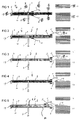
- FIG. 1 shows a schematic side view of an imaging system 1 according to the invention.
- the imaging system 1 comprises a plate imaging bed 2 having an input section 3 and an output section 4.
- printing plates are transferred from a multiple plate stack 11, 12 to the input section 3, as will be explained in more detail below.
- the printing plate is exposed to radiation from a radiation exposure unit (not shown) that is mounted on the plate imaging process and that can comprise an imaging array or a scanning beam based exposure system such as a rotating polygon laser module.
- the printing plate is transported to the output section 4 and transferred to a chemical processing unit (also not shown) that is placed near the output section 4.
- the imaging system 1 is provided with a loading device comprising a printing plate loader 5 and a paper gripper 6 for loading a printing plate from a stack to the imaging bed.
- the printing plate loader is arranged to transfer a printing plate from the stack 11, 12 to the input section 3, while the paper gripper 6 is adapted to remove an interleave paper that is positioned between subsequent printing plates on the stack 11, 12.
- both devices can advantageously be optimized for performing their specific task.
- the loader 5 and the gripper 6 are integrated in a single device.
- the printing plate loader 5 comprises a vacuum loader.
- other devices are also possible, such as a gripping element.
- the gripper 6 comprises gripping elements 15.
- Both the loader 5 and the gripper 6 are movable along the plate imaging bed 2 by means of separate upper and lower rails 9, 10, respectively, so that printing plates and interleave papers can be pulled from the stack 11, 12.
- the loader 5 and the gripper 6 are placed on common rails.
- the rails 9, 10 can be replaced by other guiding means, such as V-profiles.
- the imaging bed 2 is provided with a pivot axle 19 near the output section 4 to facilitate a pivotal movement of the bed 2 with respect to an axis extending through the axle 19.
- the pivot axle 19 is e.g. supported by two bearings.
- the pivotal movement of the bed can be performed in a plane that is oriented transverse to the bed 2, so that the input section 3 can be adjusted to the top of a stack 11, 12.
- the bed 2 comprises a bed carrier 8 providing a stiff structure.
- the plate imaging bed 2 forms a relative stiff lever arm that is pivotable with respect to the pivot axle 19.
- the height of the pivot axle is preferably fixed, e.g. at a height of circa 915 mm, in order to provide good transferring conditions for transferring a printing plate to the chemical processing unit.
- the imaging system 1 comprises a position adjusting device 7 engaging the plate imaging bed 2 remote from the pivoting axle 19 for positioning the input section 3 near the top of the multiple plate stack.
- the position adjusting device 7 comprises an actuator mechanism, such as a lead screw with a motor, a hydraulic cylinder, an air cylinder, a linear motor, a belt and motor based or a chain and motor based actuator.
- Movement of a printing plate from the input section 3 towards the output section 4 of the bed 2 can be controlled by means of a moving bed unit.
- a moving bed unit comprising a pair of cylinders each contacting an opposite side, respectively, of the printing plate.
- FIG 2 a schematic side view of the imaging system 1 during a first stage of a loading process is shown.
- the printing plate loader 5 moves via the upper rails 9 along the bed 2 towards a first stack 12.
- the stack 12 comprises multiple printing plates wherein between each two printing plates an interleave paper is positioned to avoid damage on the structure of the printing plates.
- the printing plates comprise a support substrate that can be metal or polymer based.
- Popular metal supports are aluminium based. Other metal supports include copper and/or steel.
- Polymer supports as used in flexography and polyester based plates are also possible. At least one radiation sensitive layer is coated on the support.
- the stack 12 is supported by a cassette or a Euro-pallet.
- the loader 5 lifts an upper printing plate 14 up from an interleave paper.
- the paper gripper 6 moves via the lower rails 10 towards the stack 12 and enters between the lifted printing plate 14 and the interleave paper.
- the paper gripper 6 engages the interleaving paper and holds it in place.
- the printing plate loader 5 pulls the printing plate 14 from the stack 12.
- the printing plate loader 5 drops the printing plate 14 at the input section 3 of the plate bed 2, as the printing plate loader 5 is positioned above the bed 2.
- the paper gripper 6 pulls the interleaving paper 16 from the stack 12.
- the printing plate loader 5 moves to a rest position, while the paper gripper 6 drops the interleaving paper 16 which then falls downwards under the bed 2, as the paper gripper 6 is localized under the bed 2.
- FIG 8-10 a schematic side view of the imaging system 1 is shown during a loading process from a full stack 12, a half full stack 12 and an almost empty stack 12, respectively.
- the actuator mechanism 7 adjusts the pivotal orientation of the bed 2 in such a manner that the input section 3 of the bed approaches the top of the stack 12 to be unloaded. In this way, the input section 3 follows the reducing top of the stack 12.
- Figure 11 shows a schematic side view of the imaging system 1 during a loading process from a second stack 11.
- the second stack 11 is placed at a higher position than the first stack 12. Therefore, beginning from the situation as shown in Figure 9, the input section 3 of the bed 2 is moved upwards by means of the actuator mechanism 7 until the top level of the second stack 11 is reached and the loading process can start.
- the whole configuration of the stacks and the imaging system can be pivoted, e.g. to obtain a system wherein the printing plates are oriented in a substantial vertical direction.
Landscapes
- Engineering & Computer Science (AREA)
- Manufacturing & Machinery (AREA)
- Mechanical Engineering (AREA)
- Exposure And Positioning Against Photoresist Photosensitive Materials (AREA)
- Manufacture Or Reproduction Of Printing Formes (AREA)
Abstract
Description
- The invention relates to an imaging system and a method for loading a printing plate. Traditionally, a prepress process requires the development of a negative or positive film of data to be printed. The film is subsequently copied onto a printing plate. Then, the printing plate is employed for offset printing activities. The computer-to-plate imaging process comprises a digital technology transferring text and/or images directly onto the printing plate by means of an radiation exposure unit. Thereby the intermediate film production is bypassed.
- A known imaging system for performing a computer-to-plate imaging process on printing plates comprises a plate imaging bed for exposing radiation to a printing plate, the bed being provided with an input section for receiving a printing plate and an output section for transferring the printing plate to a chemical processing unit. In operation, a loading device loads a printing plate from a multiple plate stack to the input section of the plate imaging bed.
- Such an imaging system is known. The printing plate comprises a support substrate that can be metal or polymer based. Popular metal supports are aluminium based. Other metal supports comprise copper and/or steel, but polymer supports as used in flexography and polyester based plates are also possible. On this substrate a radiation sensitive coating is provided which can easily be damaged during handling. In an initial stage, the printing plate is stacked together with a multiple set of printing plates on a multiple plate stack. During the process, individual printing plates are loaded from the stack towards the input section of the plate imaging bed by means of the loading device. Subsequently, the printing plate is locally sensitized by radiation that is exposed by the imaging system and transported to the end section of the printing plate. Then, the printing plate is transferred to an optional external conveyor system or a chemical processing unit, for plate types that require chemical processing. The conveyor or chemical processing unit is positioned adjacent the output section of the imaging bed for optional further processing.
- The multiple plate stack is supported by a supporting unit, such as a cassette. In a conventional imaging system, the height of the cassette is adjustable, so that the height of the upper plate of the stack can be kept at a desired level, thus facilitating the transfer of an upper printing plate from the stack to the imaging bed without being damaged. Further, the lower level of the stack is fixed while the loading device is movable in the vertical direction, so that an upper printing plate can be lifted from the stack and can be brought to a desired level corresponding to the height of the imaging bed.
- A disadvantage of such a loading mechanism is its complexity, causing time loss and/or increased costs. Further, the known loading mechanism is in general only suitable for handling printing plates in a specific configuration of imaging bed and stack structure.
- In practice, two or more plate stacks can be positioned near the input section of the imaging bed. A further disadvantage is, that this further increases the complexity of the height adjusting mechanisms.
-
- It is an object of the invention to provide an imaging system, wherein the disadvantages identified above are reduced. In particular, the invention aims at obtaining an imaging system which is more flexible with respect to multiple plate stacks. Thereto, according to an aspect of the invention, the input section is adjustable with respect to the output section to adjust the position of the input section to near the top of the multiple plate stack.
- By adjusting the position of the input section to near the top of the multiple plate stack, an imaging system is obtained wherein the loading device can easily transfer an upper printing plate from the stack towards the input section of the imaging bed. As a consequence, the imaging system is more flexible with respect to multiple plate stacks. By rendering the input section adjustable with respect to the output section, the position of the output section can be maintained, an optimal transfer of the printing plate towards the chemical processing unit is maintained.
- During the loading process of subsequent printing plates, the input section can follow the top of the stack, thereby minimizing the transfer distance of the printing plate. Also, stacks having different stack heights can thus be processed.
- Moreover, the system according to the invention is also more suitable with respect to various types of stacks, such as different cassette types, multiple cassettes and/or Euro-pallets. As an example, the input section can be set from near the top of a first stack to near the top of a second stack. Further, the chance that printing plates are damaged during the transfer from the stack to the input section of the imaging bed is even reduced, as the transport distance of the printing plate from the stack to the input section is minimal during transfer.
- It is noted that in this context the expression 'top of the stack' means the position of a printing plate that delimits the stack. Similarly, with this context the expression 'stack height' denotes the size of the multiple plate stack in a direction wherein the stack increases or decreases during loading and unloading, respectively, of the stack. If the stack has been loaded in a vertical direction, the top of the stack is the height of the upper printing plate.
- By providing the plate imaging bed with a pivot axle for pivoting the plate imaging bed, relative good control over adjustments of the input section position can be obtained. In a preferred embodiment, the pivot axle is arranged near the output section, so that the effect of the input section position on the output section position is mainly negligible, so that good transferring conditions for transferring the printing plate towards the chemical processing unit are provided.
- Advantageously, the plate imaging bed forms a stiff lever arm, so that the imaging bed and also the printing plate being processed remains substantially flat, thereby facilitating good exposure conditions.
- Other advantageous embodiments according to the invention are described in the following claims.
- By way of example only, embodiments of the present invention will now be described with reference to the accompanying figures in which
- Fig. 1 shows a schematic side view of an imaging system according to the invention;
- Fig. 2 shows a schematic side view of the imaging system of Figure 1 during a first stage of a loading process;
- Fig. 3 shows a schematic side view of the imaging system of Figure 1 during a second stage of a loading process;
- Fig. 4 shows a schematic side view of the imaging system of Figure 1 during a third stage of a loading process;
- Fig. 5 shows a schematic side view of the imaging system of Figure 1 during a fourth stage of a loading process;
- Fig. 6 shows a schematic side view of the imaging system of Figure 1 during a fifth stage of a loading process;
- Fig. 7 shows a schematic side view of the imaging system of Figure 1 during a sixth stage of a loading process;
- Fig. 8 shows a schematic side view of the imaging system of Figure 1 during a loading process from a full stack;
- Fig. 9 shows a schematic side view of the imaging system of Figure 1 during a loading process from a half full stack;
- Fig. 10 shows a schematic side view of the imaging system of Figure 1 during a loading process from an almost empty stack; and
- Fig. 11 shows a schematic side view of the imaging system of Figure 1 during a loading process from a second stack.
- The figures are merely schematic views of preferred embodiments according to the invention. In the figures, the same reference numbers refer to equal or corresponding parts.
- Figure 1 shows a schematic side view of an
imaging system 1 according to the invention. Theimaging system 1 comprises aplate imaging bed 2 having aninput section 3 and anoutput section 4. During a computer-to-plate imaging process, printing plates are transferred from amultiple plate stack 11, 12 to theinput section 3, as will be explained in more detail below. Subsequently, the printing plate is exposed to radiation from a radiation exposure unit (not shown) that is mounted on the plate imaging process and that can comprise an imaging array or a scanning beam based exposure system such as a rotating polygon laser module. Then, the printing plate is transported to theoutput section 4 and transferred to a chemical processing unit (also not shown) that is placed near theoutput section 4. - Further, the
imaging system 1 is provided with a loading device comprising aprinting plate loader 5 and apaper gripper 6 for loading a printing plate from a stack to the imaging bed. The printing plate loader is arranged to transfer a printing plate from thestack 11, 12 to theinput section 3, while thepaper gripper 6 is adapted to remove an interleave paper that is positioned between subsequent printing plates on thestack 11, 12. By providing aloader 5 for transferring printing plates, and apaper gripper 6 for removing interleave papers, both devices can advantageously be optimized for performing their specific task. In a more basic embodiment, theloader 5 and thegripper 6 are integrated in a single device. In a preferred embodiment, theprinting plate loader 5 comprises a vacuum loader. However, other devices are also possible, such as a gripping element. Thegripper 6 comprisesgripping elements 15. - Both the
loader 5 and thegripper 6 are movable along theplate imaging bed 2 by means of separate upper andlower rails 9, 10, respectively, so that printing plates and interleave papers can be pulled from thestack 11, 12. In another embodiment, theloader 5 and thegripper 6 are placed on common rails. Further, therails 9, 10 can be replaced by other guiding means, such as V-profiles. - The
imaging bed 2 is provided with apivot axle 19 near theoutput section 4 to facilitate a pivotal movement of thebed 2 with respect to an axis extending through theaxle 19. Thepivot axle 19 is e.g. supported by two bearings. The pivotal movement of the bed can be performed in a plane that is oriented transverse to thebed 2, so that theinput section 3 can be adjusted to the top of astack 11, 12. Thebed 2 comprises abed carrier 8 providing a stiff structure. As a consequence, theplate imaging bed 2 forms a relative stiff lever arm that is pivotable with respect to thepivot axle 19. The height of the pivot axle is preferably fixed, e.g. at a height of circa 915 mm, in order to provide good transferring conditions for transferring a printing plate to the chemical processing unit. - Further, the
imaging system 1 comprises a position adjusting device 7 engaging theplate imaging bed 2 remote from the pivotingaxle 19 for positioning theinput section 3 near the top of the multiple plate stack. In the position adjusting device as shown in Figure 1, the position adjusting device 7 comprises an actuator mechanism, such as a lead screw with a motor, a hydraulic cylinder, an air cylinder, a linear motor, a belt and motor based or a chain and motor based actuator. - Movement of a printing plate from the
input section 3 towards theoutput section 4 of thebed 2 can be controlled by means of a moving bed unit. However, also other movement control systems can be employed, such as a guiding unit comprising a pair of cylinders each contacting an opposite side, respectively, of the printing plate. - In Figure 2 a schematic side view of the
imaging system 1 during a first stage of a loading process is shown. Theprinting plate loader 5 moves via the upper rails 9 along thebed 2 towards afirst stack 12. Thestack 12 comprises multiple printing plates wherein between each two printing plates an interleave paper is positioned to avoid damage on the structure of the printing plates. The printing plates comprise a support substrate that can be metal or polymer based. Popular metal supports are aluminium based. Other metal supports include copper and/or steel. Polymer supports as used in flexography and polyester based plates are also possible. At least one radiation sensitive layer is coated on the support. Thestack 12 is supported by a cassette or a Euro-pallet. In Figure 2, theloader 5 lifts anupper printing plate 14 up from an interleave paper. - During a second stage of the loading process, as shown in Figure 3, the
paper gripper 6 moves via thelower rails 10 towards thestack 12 and enters between the liftedprinting plate 14 and the interleave paper. - During a third stage of the loading process, as shown in Figure 4, the
paper gripper 6 engages the interleaving paper and holds it in place. - During a fourth stage of the loading process, as shown in Figure 5, the
printing plate loader 5 pulls theprinting plate 14 from thestack 12. - During a fifth stage of the loading process, as shown in Figure 6, the
printing plate loader 5 drops theprinting plate 14 at theinput section 3 of theplate bed 2, as theprinting plate loader 5 is positioned above thebed 2. Thepaper gripper 6 pulls the interleavingpaper 16 from thestack 12. - During a sixth stage of the loading process, as shown in Figure 7, the
printing plate loader 5 moves to a rest position, while thepaper gripper 6 drops the interleavingpaper 16 which then falls downwards under thebed 2, as thepaper gripper 6 is localized under thebed 2. - In Figure 8-10, a schematic side view of the
imaging system 1 is shown during a loading process from afull stack 12, a halffull stack 12 and an almostempty stack 12, respectively. As can be seen in the Figures 8-10, the actuator mechanism 7 adjusts the pivotal orientation of thebed 2 in such a manner that theinput section 3 of the bed approaches the top of thestack 12 to be unloaded. In this way, theinput section 3 follows the reducing top of thestack 12. - Further, Figure 11 shows a schematic side view of the
imaging system 1 during a loading process from a second stack 11. The second stack 11 is placed at a higher position than thefirst stack 12. Therefore, beginning from the situation as shown in Figure 9, theinput section 3 of thebed 2 is moved upwards by means of the actuator mechanism 7 until the top level of the second stack 11 is reached and the loading process can start. - The invention is not restricted to the embodiments described herein. It will be understood that many variants are possible.
- Instead of using a polygon laser module, alternative exposure systems for irradiating the radiation sensitive surface of the printing plate such as imaging arrays or galvo-resonator based scanning laser beam modulators can be employed.
- Further, the whole configuration of the stacks and the imaging system can be pivoted, e.g. to obtain a system wherein the printing plates are oriented in a substantial vertical direction.
- Other such variants will be obvious for the person skilled in the art and are considered to lie within the scope of the invention as formulated in the following claims.
Claims (13)
- An imaging system for performing a computer-to-plate imaging process on printing plates, comprising a plate imaging bed for exposing radiation to a printing plate, the bed being provided with an input section for receiving a printing plate and an output section for transferring the printing plate to a chemical processing unit, further comprising a loading device for loading the printing plate from a multiple plate stack to the input section of the plate imaging bed, wherein the input section is adjustable with respect to the output section to adjust the position of the input section to near the top of the multiple plate stack.
- An imaging system according to claim 1, wherein the plate imaging bed comprises a pivoting axle for pivoting the plate imaging bed.
- An imaging system according to claim 1 or 2, wherein the pivoting axle is arranged near the output section.
- An imaging system according to any previous claim, wherein the plate imaging bed forms a stiff lever arm.
- An imaging system according to any previous claim, comprising a position adjusting device engaging the plate imaging bed remote from the pivoting axle for positioning the input section near the top of the multiple plate stack.
- An imaging system according to any previous claim, wherein the position adjusting device comprises an actuator mechanism.
- An imaging system according to any previous claim, wherein the loading device comprises a printing plate loader and a paper gripper.
- An imaging system according to any previous claim, wherein the printing plate loader and/or the paper gripper are movable along the plate imaging bed between the input section and the output section.
- An imaging system according to any pervious claim, wherein the printing plate loader comprises a vacuum loader.
- A method for loading a printing plate from a multiple plate stack to an input section of a plate imaging bed in an imaging system for performing a computer-to-plate imaging process on printing plates, the method comprising adjusting the position of the input section to near the top of the multiple plate stack.
- A method according to claim 10, further comprising gripping an interleave paper that is positioned between subsequent printing plates.
- A method according to claim 10 or 11, further comprising transporting the printing plate from the input section to an output section of the plate imaging bed by means of a moving bed unit.
- A method according to claim 10 or 11, further comprising transporting the printing plate from the input section to an output section of the plate imaging bed by means of a guiding unit comprising a pair of cylinders each contacting an opposite side, respectively, of the printing plate.
Priority Applications (4)
| Application Number | Priority Date | Filing Date | Title |
|---|---|---|---|
| DE602005014642T DE602005014642D1 (en) | 2005-10-04 | 2005-10-04 | Image forming system and method for loading printing plates |
| EP05077248A EP1772262B1 (en) | 2005-10-04 | 2005-10-04 | Imaging system and method for loading a printing plate |
| US11/542,490 US7610854B2 (en) | 2005-10-04 | 2006-10-03 | Imaging system and method for loading a printing plate |
| JP2006273021A JP2007133381A (en) | 2005-10-04 | 2006-10-04 | Imaging system and method for loading printing plate |
Applications Claiming Priority (1)
| Application Number | Priority Date | Filing Date | Title |
|---|---|---|---|
| EP05077248A EP1772262B1 (en) | 2005-10-04 | 2005-10-04 | Imaging system and method for loading a printing plate |
Publications (2)
| Publication Number | Publication Date |
|---|---|
| EP1772262A1 true EP1772262A1 (en) | 2007-04-11 |
| EP1772262B1 EP1772262B1 (en) | 2009-05-27 |
Family
ID=35207164
Family Applications (1)
| Application Number | Title | Priority Date | Filing Date |
|---|---|---|---|
| EP05077248A Expired - Lifetime EP1772262B1 (en) | 2005-10-04 | 2005-10-04 | Imaging system and method for loading a printing plate |
Country Status (4)
| Country | Link |
|---|---|
| US (1) | US7610854B2 (en) |
| EP (1) | EP1772262B1 (en) |
| JP (1) | JP2007133381A (en) |
| DE (1) | DE602005014642D1 (en) |
Cited By (2)
| Publication number | Priority date | Publication date | Assignee | Title |
|---|---|---|---|---|
| WO2010056274A1 (en) * | 2008-11-13 | 2010-05-20 | Eastman Kodak Company | An apparatus for cassette loading |
| EP2653419A1 (en) | 2012-04-19 | 2013-10-23 | Xeikon IP B.V. | A handling system for transferring printing plates and a method |
Citations (4)
| Publication number | Priority date | Publication date | Assignee | Title |
|---|---|---|---|---|
| DE3828439A1 (en) * | 1987-02-24 | 1990-03-08 | Kodak Ag | Automatic film-loading device for sheet-film cassettes |
| WO2000049463A1 (en) | 1999-02-17 | 2000-08-24 | Kodak Polychrome Graphics Company Ltd. | Flat bed platesetter system |
| EP1473153A2 (en) | 2003-04-09 | 2004-11-03 | Esko-Graphics A/S | Method and apparatus for loading and unloading flexographic plates for computer-to-plate imaging |
| US20050132916A1 (en) * | 2003-12-18 | 2005-06-23 | Heidelberger Druckmaschinen Aktiengesellschaft | Transport apparatus for printing plates and method of operating the transport apparatus |
Family Cites Families (7)
| Publication number | Priority date | Publication date | Assignee | Title |
|---|---|---|---|---|
| US4178097A (en) * | 1977-09-06 | 1979-12-11 | Beach Manufacturing Corporation | Automatic lithographic plate processor |
| DE3442755A1 (en) * | 1984-11-23 | 1986-05-28 | Hoechst Ag, 6230 Frankfurt | DEVICE FOR ELECTROPHOTOGRAPHIC PRODUCTION OF PRINTING FORMS |
| JP2887281B2 (en) * | 1993-03-11 | 1999-04-26 | 大日本スクリーン製造株式会社 | Proximity exposure equipment |
| JPH07215559A (en) * | 1994-02-08 | 1995-08-15 | Fuji Photo Film Co Ltd | Sorting method for print plate |
| JP2002284402A (en) * | 2001-03-28 | 2002-10-03 | Fuji Photo Film Co Ltd | Plate feeding device |
| JP2003076032A (en) * | 2001-09-04 | 2003-03-14 | Fuji Photo Film Co Ltd | Device for conveying and guiding printing plate |
| JP4187202B2 (en) * | 2003-05-01 | 2008-11-26 | 清水製作株式会社 | Printing plate transfer machine, plate storage cart, printing plate transfer device and printing plate sorting device |
-
2005
- 2005-10-04 DE DE602005014642T patent/DE602005014642D1/en not_active Expired - Lifetime
- 2005-10-04 EP EP05077248A patent/EP1772262B1/en not_active Expired - Lifetime
-
2006
- 2006-10-03 US US11/542,490 patent/US7610854B2/en not_active Expired - Fee Related
- 2006-10-04 JP JP2006273021A patent/JP2007133381A/en not_active Ceased
Patent Citations (4)
| Publication number | Priority date | Publication date | Assignee | Title |
|---|---|---|---|---|
| DE3828439A1 (en) * | 1987-02-24 | 1990-03-08 | Kodak Ag | Automatic film-loading device for sheet-film cassettes |
| WO2000049463A1 (en) | 1999-02-17 | 2000-08-24 | Kodak Polychrome Graphics Company Ltd. | Flat bed platesetter system |
| EP1473153A2 (en) | 2003-04-09 | 2004-11-03 | Esko-Graphics A/S | Method and apparatus for loading and unloading flexographic plates for computer-to-plate imaging |
| US20050132916A1 (en) * | 2003-12-18 | 2005-06-23 | Heidelberger Druckmaschinen Aktiengesellschaft | Transport apparatus for printing plates and method of operating the transport apparatus |
Cited By (3)
| Publication number | Priority date | Publication date | Assignee | Title |
|---|---|---|---|---|
| WO2010056274A1 (en) * | 2008-11-13 | 2010-05-20 | Eastman Kodak Company | An apparatus for cassette loading |
| US8739702B2 (en) | 2008-11-13 | 2014-06-03 | Eastman Kodak Company | Printing plate loading apparatus for loading plates from either a plate stack or cassette |
| EP2653419A1 (en) | 2012-04-19 | 2013-10-23 | Xeikon IP B.V. | A handling system for transferring printing plates and a method |
Also Published As
| Publication number | Publication date |
|---|---|
| US7610854B2 (en) | 2009-11-03 |
| DE602005014642D1 (en) | 2009-07-09 |
| US20070084374A1 (en) | 2007-04-19 |
| JP2007133381A (en) | 2007-05-31 |
| EP1772262B1 (en) | 2009-05-27 |
Similar Documents
| Publication | Publication Date | Title |
|---|---|---|
| EP2125588B1 (en) | Separating media combinations from a media stack | |
| EP2109576B1 (en) | Method for storing slip-sheets | |
| US8757060B2 (en) | Method and apparatus for loading and unloading flexographic plates for computer-to-plate imaging including separate loading and unloading areas | |
| US8210104B2 (en) | Moveable printing plate registration member | |
| EP1772262B1 (en) | Imaging system and method for loading a printing plate | |
| US7000543B2 (en) | Method and apparatus for loading and unloading flexographic plates for computer-to-plate imaging | |
| US7614619B2 (en) | Methods and apparatus for separating image recordable materials from a media stack | |
| WO2010047782A1 (en) | Moveable printing plate registration member | |
| US6981447B2 (en) | Method and apparatus for loading and unloading flexographic plates for computer-to-plate imaging | |
| EP4095072B1 (en) | Sheet supply device | |
| US8276513B2 (en) | Method for handling printing plates and adjusting the spacing between plates | |
| EP2155491B1 (en) | Method and apparatus for unloading printing plates | |
| EP2304502B1 (en) | Print plate handling system | |
| WO2009097102A1 (en) | Separating slip-sheets from image recordable material | |
| WO1996031807A2 (en) | Platesetter | |
| US6886825B2 (en) | Plate handling system | |
| CN220519488U (en) | Feeding device of wafer direct writing machine | |
| US20240140743A1 (en) | Printing plate picking system and process | |
| JP2006058782A (en) | Substrate suction mechanism, substrate suction method, substrate carrying apparatus and image forming apparatus | |
| US20100018423A1 (en) | Printing plate transferring system | |
| JP3587442B2 (en) | Laser plotter | |
| AU2002244721A1 (en) | Plate handling system | |
| JP2003050471A (en) | Plate feeding device of plate making device | |
| JP2006058783A (en) | Substrate positioning mechanism, substrate positioning method, substrate carrying apparatus and image forming apparatus | |
| JP2002323772A (en) | Automatic exposing device for printing plate |
Legal Events
| Date | Code | Title | Description |
|---|---|---|---|
| PUAI | Public reference made under article 153(3) epc to a published international application that has entered the european phase |
Free format text: ORIGINAL CODE: 0009012 |
|
| AK | Designated contracting states |
Kind code of ref document: A1 Designated state(s): AT BE BG CH CY CZ DE DK EE ES FI FR GB GR HU IE IS IT LI LT LU LV MC NL PL PT RO SE SI SK TR |
|
| AX | Request for extension of the european patent |
Extension state: AL BA HR MK YU |
|
| 17P | Request for examination filed |
Effective date: 20070807 |
|
| 17Q | First examination report despatched |
Effective date: 20071009 |
|
| AKX | Designation fees paid |
Designated state(s): DE FR GB |
|
| GRAP | Despatch of communication of intention to grant a patent |
Free format text: ORIGINAL CODE: EPIDOSNIGR1 |
|
| RAP1 | Party data changed (applicant data changed or rights of an application transferred) |
Owner name: AGFA GRAPHICS NV Owner name: PUNCH GRAPHIX INTERNATIONAL N.V. |
|
| GRAS | Grant fee paid |
Free format text: ORIGINAL CODE: EPIDOSNIGR3 |
|
| GRAA | (expected) grant |
Free format text: ORIGINAL CODE: 0009210 |
|
| AK | Designated contracting states |
Kind code of ref document: B1 Designated state(s): DE FR GB |
|
| REG | Reference to a national code |
Ref country code: GB Ref legal event code: FG4D |
|
| REF | Corresponds to: |
Ref document number: 602005014642 Country of ref document: DE Date of ref document: 20090709 Kind code of ref document: P |
|
| PLBE | No opposition filed within time limit |
Free format text: ORIGINAL CODE: 0009261 |
|
| STAA | Information on the status of an ep patent application or granted ep patent |
Free format text: STATUS: NO OPPOSITION FILED WITHIN TIME LIMIT |
|
| 26N | No opposition filed |
Effective date: 20100302 |
|
| REG | Reference to a national code |
Ref country code: FR Ref legal event code: PLFP Year of fee payment: 11 |
|
| REG | Reference to a national code |
Ref country code: FR Ref legal event code: PLFP Year of fee payment: 12 |
|
| REG | Reference to a national code |
Ref country code: FR Ref legal event code: PLFP Year of fee payment: 13 |
|
| REG | Reference to a national code |
Ref country code: DE Ref legal event code: R081 Ref document number: 602005014642 Country of ref document: DE Owner name: XEIKON PREPRESS NV, BE Free format text: FORMER OWNERS: AGFA GRAPHICS N.V., MORTSEL, BE; PUNCH GRAPHIX INTERNATIONAL N.V., LIER, BE Ref country code: DE Ref legal event code: R082 Ref document number: 602005014642 Country of ref document: DE Representative=s name: DOMPATENT VON KREISLER SELTING WERNER - PARTNE, DE Ref country code: DE Ref legal event code: R081 Ref document number: 602005014642 Country of ref document: DE Owner name: PUNCH GRAPHIX INTERNATIONAL N.V., BE Free format text: FORMER OWNERS: AGFA GRAPHICS N.V., MORTSEL, BE; PUNCH GRAPHIX INTERNATIONAL N.V., LIER, BE Ref country code: DE Ref legal event code: R081 Ref document number: 602005014642 Country of ref document: DE Owner name: AGFA NV, BE Free format text: FORMER OWNERS: AGFA GRAPHICS N.V., MORTSEL, BE; PUNCH GRAPHIX INTERNATIONAL N.V., LIER, BE |
|
| REG | Reference to a national code |
Ref country code: FR Ref legal event code: PLFP Year of fee payment: 14 |
|
| REG | Reference to a national code |
Ref country code: DE Ref legal event code: R081 Ref document number: 602005014642 Country of ref document: DE Owner name: XEIKON PREPRESS NV, BE Free format text: FORMER OWNERS: AGFA NV, MORTSEL, BE; PUNCH GRAPHIX INTERNATIONAL N.V., LIER, BE Ref country code: DE Ref legal event code: R081 Ref document number: 602005014642 Country of ref document: DE Owner name: AGFA NV, BE Free format text: FORMER OWNERS: AGFA NV, MORTSEL, BE; PUNCH GRAPHIX INTERNATIONAL N.V., LIER, BE Ref country code: DE Ref legal event code: R081 Ref document number: 602005014642 Country of ref document: DE Owner name: XSYS PREPRESS N.V., BE Free format text: FORMER OWNERS: AGFA NV, MORTSEL, BE; PUNCH GRAPHIX INTERNATIONAL N.V., LIER, BE |
|
| REG | Reference to a national code |
Ref country code: GB Ref legal event code: 732E Free format text: REGISTERED BETWEEN 20220203 AND 20220209 |
|
| P01 | Opt-out of the competence of the unified patent court (upc) registered |
Effective date: 20230526 |
|
| REG | Reference to a national code |
Ref country code: DE Ref legal event code: R082 Ref document number: 602005014642 Country of ref document: DE Representative=s name: ARNOLD & SIEDSMA, DE Ref country code: DE Ref legal event code: R081 Ref document number: 602005014642 Country of ref document: DE Owner name: XSYS PREPRESS N.V., BE Free format text: FORMER OWNERS: AGFA NV, MORTSEL, BE; XEIKON PREPRESS NV, LEPER, BE Ref country code: DE Ref legal event code: R081 Ref document number: 602005014642 Country of ref document: DE Owner name: AGFA NV, BE Free format text: FORMER OWNERS: AGFA NV, MORTSEL, BE; XEIKON PREPRESS NV, LEPER, BE |
|
| PGFP | Annual fee paid to national office [announced via postgrant information from national office to epo] |
Ref country code: DE Payment date: 20241021 Year of fee payment: 20 |
|
| PGFP | Annual fee paid to national office [announced via postgrant information from national office to epo] |
Ref country code: GB Payment date: 20241022 Year of fee payment: 20 |
|
| PGFP | Annual fee paid to national office [announced via postgrant information from national office to epo] |
Ref country code: FR Payment date: 20241021 Year of fee payment: 20 |
|
| REG | Reference to a national code |
Ref country code: DE Ref legal event code: R071 Ref document number: 602005014642 Country of ref document: DE |
|
| REG | Reference to a national code |
Ref country code: GB Ref legal event code: PE20 Expiry date: 20251003 |