EP1772252B1 - Blow molded receptacle containing a hole - Google Patents
Blow molded receptacle containing a hole Download PDFInfo
- Publication number
- EP1772252B1 EP1772252B1 EP06291562.4A EP06291562A EP1772252B1 EP 1772252 B1 EP1772252 B1 EP 1772252B1 EP 06291562 A EP06291562 A EP 06291562A EP 1772252 B1 EP1772252 B1 EP 1772252B1
- Authority
- EP
- European Patent Office
- Prior art keywords
- receptacle
- punch
- mold
- sidewall
- hole
- Prior art date
- Legal status (The legal status is an assumption and is not a legal conclusion. Google has not performed a legal analysis and makes no representation as to the accuracy of the status listed.)
- Active
Links
Images






Classifications
-
- B—PERFORMING OPERATIONS; TRANSPORTING
- B42—BOOKBINDING; ALBUMS; FILES; SPECIAL PRINTED MATTER
- B42F—SHEETS TEMPORARILY ATTACHED TOGETHER; FILING APPLIANCES; FILE CARDS; INDEXING
- B42F7/00—Filing appliances without fastening means
- B42F7/14—Boxes
- B42F7/145—Boxes for vertically storing documents
-
- B—PERFORMING OPERATIONS; TRANSPORTING
- B29—WORKING OF PLASTICS; WORKING OF SUBSTANCES IN A PLASTIC STATE IN GENERAL
- B29C—SHAPING OR JOINING OF PLASTICS; SHAPING OF MATERIAL IN A PLASTIC STATE, NOT OTHERWISE PROVIDED FOR; AFTER-TREATMENT OF THE SHAPED PRODUCTS, e.g. REPAIRING
- B29C49/00—Blow-moulding, i.e. blowing a preform or parison to a desired shape within a mould; Apparatus therefor
- B29C49/42—Component parts, details or accessories; Auxiliary operations
- B29C49/48—Moulds
- B29C49/50—Moulds having cutting or deflashing means
-
- B—PERFORMING OPERATIONS; TRANSPORTING
- B29—WORKING OF PLASTICS; WORKING OF SUBSTANCES IN A PLASTIC STATE IN GENERAL
- B29C—SHAPING OR JOINING OF PLASTICS; SHAPING OF MATERIAL IN A PLASTIC STATE, NOT OTHERWISE PROVIDED FOR; AFTER-TREATMENT OF THE SHAPED PRODUCTS, e.g. REPAIRING
- B29C49/00—Blow-moulding, i.e. blowing a preform or parison to a desired shape within a mould; Apparatus therefor
- B29C49/42—Component parts, details or accessories; Auxiliary operations
- B29C49/48—Moulds
- B29C2049/4879—Moulds characterised by mould configurations
-
- B—PERFORMING OPERATIONS; TRANSPORTING
- B29—WORKING OF PLASTICS; WORKING OF SUBSTANCES IN A PLASTIC STATE IN GENERAL
- B29C—SHAPING OR JOINING OF PLASTICS; SHAPING OF MATERIAL IN A PLASTIC STATE, NOT OTHERWISE PROVIDED FOR; AFTER-TREATMENT OF THE SHAPED PRODUCTS, e.g. REPAIRING
- B29C49/00—Blow-moulding, i.e. blowing a preform or parison to a desired shape within a mould; Apparatus therefor
- B29C49/42—Component parts, details or accessories; Auxiliary operations
- B29C49/48—Moulds
- B29C2049/4879—Moulds characterised by mould configurations
- B29C2049/4882—Mould cavity geometry
- B29C2049/4883—Mould cavity geometry having cavity parts avoiding preform contact, e.g. partial free blow
-
- B—PERFORMING OPERATIONS; TRANSPORTING
- B29—WORKING OF PLASTICS; WORKING OF SUBSTANCES IN A PLASTIC STATE IN GENERAL
- B29C—SHAPING OR JOINING OF PLASTICS; SHAPING OF MATERIAL IN A PLASTIC STATE, NOT OTHERWISE PROVIDED FOR; AFTER-TREATMENT OF THE SHAPED PRODUCTS, e.g. REPAIRING
- B29C2793/00—Shaping techniques involving a cutting or machining operation
- B29C2793/0009—Cutting out
- B29C2793/0018—Cutting out for making a hole
-
- B—PERFORMING OPERATIONS; TRANSPORTING
- B29—WORKING OF PLASTICS; WORKING OF SUBSTANCES IN A PLASTIC STATE IN GENERAL
- B29C—SHAPING OR JOINING OF PLASTICS; SHAPING OF MATERIAL IN A PLASTIC STATE, NOT OTHERWISE PROVIDED FOR; AFTER-TREATMENT OF THE SHAPED PRODUCTS, e.g. REPAIRING
- B29C2793/00—Shaping techniques involving a cutting or machining operation
- B29C2793/0027—Cutting off
-
- B—PERFORMING OPERATIONS; TRANSPORTING
- B29—WORKING OF PLASTICS; WORKING OF SUBSTANCES IN A PLASTIC STATE IN GENERAL
- B29C—SHAPING OR JOINING OF PLASTICS; SHAPING OF MATERIAL IN A PLASTIC STATE, NOT OTHERWISE PROVIDED FOR; AFTER-TREATMENT OF THE SHAPED PRODUCTS, e.g. REPAIRING
- B29C2793/00—Shaping techniques involving a cutting or machining operation
- B29C2793/0045—Perforating
-
- B—PERFORMING OPERATIONS; TRANSPORTING
- B29—WORKING OF PLASTICS; WORKING OF SUBSTANCES IN A PLASTIC STATE IN GENERAL
- B29C—SHAPING OR JOINING OF PLASTICS; SHAPING OF MATERIAL IN A PLASTIC STATE, NOT OTHERWISE PROVIDED FOR; AFTER-TREATMENT OF THE SHAPED PRODUCTS, e.g. REPAIRING
- B29C2793/00—Shaping techniques involving a cutting or machining operation
- B29C2793/009—Shaping techniques involving a cutting or machining operation after shaping
-
- Y—GENERAL TAGGING OF NEW TECHNOLOGICAL DEVELOPMENTS; GENERAL TAGGING OF CROSS-SECTIONAL TECHNOLOGIES SPANNING OVER SEVERAL SECTIONS OF THE IPC; TECHNICAL SUBJECTS COVERED BY FORMER USPC CROSS-REFERENCE ART COLLECTIONS [XRACs] AND DIGESTS
- Y10—TECHNICAL SUBJECTS COVERED BY FORMER USPC
- Y10T—TECHNICAL SUBJECTS COVERED BY FORMER US CLASSIFICATION
- Y10T428/00—Stock material or miscellaneous articles
- Y10T428/13—Hollow or container type article [e.g., tube, vase, etc.]
-
- Y—GENERAL TAGGING OF NEW TECHNOLOGICAL DEVELOPMENTS; GENERAL TAGGING OF CROSS-SECTIONAL TECHNOLOGIES SPANNING OVER SEVERAL SECTIONS OF THE IPC; TECHNICAL SUBJECTS COVERED BY FORMER USPC CROSS-REFERENCE ART COLLECTIONS [XRACs] AND DIGESTS
- Y10—TECHNICAL SUBJECTS COVERED BY FORMER USPC
- Y10T—TECHNICAL SUBJECTS COVERED BY FORMER US CLASSIFICATION
- Y10T428/00—Stock material or miscellaneous articles
- Y10T428/13—Hollow or container type article [e.g., tube, vase, etc.]
- Y10T428/1352—Polymer or resin containing [i.e., natural or synthetic]
Definitions
- the present invention relates to blow molded articles.
- blow-molding as a method for manufacturing various sorts of articles is generally well known.
- this process involves the use of a mold consisting of two separate halves or portions having cavities of particularly desired shapes and sizes.
- a mold consisting of two separate halves or portions having cavities of particularly desired shapes and sizes.
- one extrudes a large-diameter, sealed tube of molten material commonly referred to as a "parison"
- places the tube between the mold halves places the tube between the mold halves, and closes the mold around the tube.
- Fluid pressure is then introduced into the tube, forcing the molten tube against the walls of the cavities, conforming the tube to the shape thereof.
- the pressure is maintained until the molten material cools and solidifies.
- the pressure is then released, the mold halves are pulled apart, and the hardened article is ejected therefrom.
- US 2003/102605 describes an apparatus for blow molding bottles having a hole formed in a molded interior recess.
- US 3327841 discloses preamble of claim 1 and describes a receptable of molded thermo plastic comprising hinged complementary portions.
- the mold in which the parison is placed often includes a first half, which has a recessed surface that serves as part of the mold cavity surface against which the wall of the blow molded article is blown, and a "core" half, which generally contains at least one projecting (or “male") section, over which the molten parison drapes as the mold is closed.
- a first half which has a recessed surface that serves as part of the mold cavity surface against which the wall of the blow molded article is blown
- a “core" half which generally contains at least one projecting (or “male”) section, over which the molten parison drapes as the mold is closed.
- molten material is pressed against the projecting mold section, conforming the tube to the shape thereof, where it cools, shrinks, and solidifies.
- the projecting section of the mold core can be used to cause a large portion of the article to a thin, double wall structure, while the remainder to the article-such as the perimeter surrounding the thin portion, may comprises a thicker double wall structure.
- One way in which these types of articles can be improved, however, is by utilizing the ability to create space between the walls to produce articles that can hold items, such as machine manuals or accessories. It is known that one way of doing this is to create a double wall article using two mold halves that have recessed mold surfaces that are fairly well spaced apart when the mold is in a closed position, such that a wide cavity is created therebetween, where the surface of a punch comprises part of one of the mold surfaces. The punch, when in an unactivated position, forms a portion of mold surface, against which the walls of the blow molded case are blown. Then, at a predetermined interval, before the walls of the case are fully hardened, the punch is moved to an activated position, creating a hole in the wall of the case.
- the punch generally moves in the direction in which the mold portions are moved when the mold is closed. This allows the punching forces to be backed by the press portion of the mold and allows for relatively uncomplicated part removal, and allows for minor angles and steps incorporated in the punch cylinders. Accordingly, the resultant holes are parallel to the parting line and serve to remove a portion of one the walls that forms the rigid, double wall structure. While these devices are very advantageous in applications such as cases and other types of closeable containers, they may not be practical in other applications.
- This type of arrangement may be desired in a wide variety of situations. For example, it may be desired to vertically orient a receptacle by mounting it to a machine or a vehicle, such as, for example, a tractor or forklift, in order to house documents or books that may need to be accessed by the user, such as instruction/operation manuals, maintenance records, or floor layouts. Alternatively, it may be desired to mount such a receptacle to certain machinery in order to hold other types of items, such as, for example, to an aerial lift in order to house safety harness equipment. Additionally, there may also be applications in which it is desirable to retain the integrity of the double wall structure along substantially the entire length of the receptacle.
- blow molded, double wall receptacle with an opening to the cavity between the walls that is somewhat horizontal when the receptacle is oriented in a vertical position, as well as a system for punching such a hole.
- blow molded, double wall receptacle that essentially retains a double wall structure along its length.
- punching a hole in a somewhat horizontal wall as described above presents several challenges. For example, shrinkage of the hardened plastic onto the sidewalls of a mold core can sometimes restrict the punching action and prohibit part removal. Additionally, the force supplied by the punch cylinder will sometimes be insufficient to cut through the wall, for several reasons. First, because the process involves a sidewall, and thus, the punching action must occur substantially perpendicular to the open-close direction of the mold, the cylinder will not be supported by the press portion of the mold, and therefore, the cylinder will have to be even larger to supply the necessary power and speed. At the same time, if the cylinder is located in the mold core, the size of the cylinder is necessarily limited due to space constraints. Similarly, the positioning of the punch controlled by a cylinder in-line with the punch is limited due to the diameter of the cylinder, and thus, the punch could not be located at the top of the mold core in order accommodate for the width of the cylinder.
- This disclosure relates also to a system for creating a blow molded, double wall receptacle that essentially maintains its double wall structure along its length.
- An apparatus for creating a blow-molded receptacle which includes a first mold portion, and a mold core having a molding surface against which a wall of the blow molded receptacle is blown during blow molding, the mold core being positionable adjacent the first mold portion to at least partially enclose a cavity, wherein the mold core comprises a base surface, a raised portion extending transversely from the base surface and into the cavity, the raised portion having an outer surface and a side surface, the side surface having an opening therein, and a punch located in the opening of the side surface such that, when the punch is in a first position, the molding surface includes at least part of the punch and, when the punch is in a second position, at least part of the punch is extended past the wall of the blow molded article and into the cavity such that a hole is created in the wall of the blow molded case.
- the apparatus includes a fluid cylinder mounted the mold core, a linear bearing mounted to the mold core, a shaft connected to the cylinder and disposed in the bearing such that actuating the cylinder displaces the shaft longitudinally through the bearing, and a mounting bar by which the punch is mounted to the shaft such that, when the shaft is longitudinally displaced, the punch is moved in a direction parallel to the shaft.
- the disclosure comprises an apparatus for creating a blow-molded receptacle, including a mold comprising first and second mold portions that, when located adjacent each other, at least partially enclose a cavity and at least partly define a molding surface against which a wall of the blow molded receptacle is blown during blow molding, wherein the second mold portion comprises a raised portion extending into the cavity, the raised portion having an outer surface and a side surface, the side surface having an opening therein, and a punch located in the opening of the side surface such that, when the punch is in a first position, the molding surface includes at least part of the punch and, when the punch is in a second position, at least part of the punch is extended past the wall of the blow molded article and into the cavity such that a hole is created in the wall of the blow molded case.
- the disclosure comprises a method for creating a blow-molded receptacle, including providing a mold comprising a first mold portion and a mold core, the mold core having a raised portion with an outer surface and a side surface, positioning the first mold portion and the mold core adjacent each other to create a cavity having a molding surface against which a wall of the blow molded article is blown, blowing the wall of the blow molded receptacle against the molding surface, thereby creating a double wall article with a sidewall corresponding to the side surface of the raised portion of the mold core, and creating a hole in the sidewall.
- the invention relates to a blow molded receptacle, including a double wall, blow molded body, the body having first and second sides at least partially enclosing a cavity therebetween, wherein the second side includes an unraised portion and a raised portion extending transversely from the unraised portion, the raised portion having an outer wall and a sidewall, such that the cavity is wider between the outer wall and the first side than between the unraised portion and the first side, and wherein the sidewall has a hole therethrough.
- FIG. 1A-C a typical example of a receptacle is illustrated in Figure 1 .
- the terms “top,” “bottom,” “above,” “below,” “over,” “under,” “above,” “beneath,” “on top,” “underneath,” “up,” “down,” “upper,” “lower,” “front,” “rear,” “back,” “forward” and “backward” refer to the objects referenced when in the orientation illustrated in the drawings.
- the receptacle includes a blow-molded, double wall body 22 having a first side 24 and a second side 26, which at least partially enclose a cavity 28 therebetween.
- the second side 26 includes an unraised portion 30 and a raised portion 32 extending transversely from the unraised portion 30.
- the raised portion 32 includes an outer wall 34 and a sidewall 36.
- the sidewall 26 is inclined at an angle ( ⁇ ) of at least forty five degrees relative the outer wall 34, and, in certain advantageous embodiments, is substantially perpendicular thereto.
- the sidewall 36 has a hole 38 therethrough, thereby exposing part of the cavity 28 such that items can be inserted in this space.
- the first side 24 has a one or more apertures 40 adapted to receive fasteners for mounting the body 22 to an object 42, such as a machine or vehicle, as illustrated In Figure 1D .
- a lid portion is connected to the body 22 in order to close the receptacle and shield the contents thereof from the elements or other potentially harmful substances.
- the lid portion comprises two hinged segments 52, 54 for closing the top and side of the receptacle, respectively. When the lid portion is in closed position, segment 54 extends down at least to sidewall 36, thereby covering the unraised portion 30, sidewall 36, and hole 38 of the second side 26.
- the double wall body 22 includes an end wall 56, and thus, the lid portion is simply connected thereto and, when in a closed position, extends down to at least sidewall 36. In this way, any items that are disposed in the hole 38 and resting against the unraised portion 30 of the second side 26.
- a mold 102 comprises a first mold portion 104 and a second mold portion 106, which, when located adjacent each other along a seam 108, at least partially enclose a cavity 128 and form a molding surface 129.
- the second mold portion 106 comprises a mold core having a base surface 130 and a raised portion 132 extending upwardly from the base surface 130.
- the base surface 130 extends around the raised portion 132, thereby creating a gap 133 between the side surface 136 and the molding surface 129 around the perimeter of the raised portion 132.
- the raised portion 132 includes an outer surface 134 and a side surface 136.
- the side surface 136 is inclined at an angle ( ⁇ ) of at least forty five degrees relative the outer surface 134, and, in certain advantageous embodiments, is substantially perpendicular thereto.
- a parison (not shown) is placed between the mold portions 104, 106, which are then pressed adjacent each other.
- the cavity 128 encloses the majority of the parison, and any unnecessary portions of the parison are pinched off at the seam 108 between the two mold portions 104, 106.
- Fluid pressure is then introduced through an inlet (not shown), which blows the parison against the molding surface 129, thereby molding the parison into the shape of the receptacle, and the side surface 136 causes the formation of the inner sidewall 36 on the receptacle.
- the pressure is maintained until the molten material cools and hardens, during which time a punch 160 is employed to create the hole 38 in the sidewall 36, as is further explained below.
- the first and second mold portions 104, 106 are then separated, the molded receptacle is removed from the mold 102, and any excess flash resulting from the parison being pinched off is cut or broken away from the container receptacle.
- the mold 102 includes a punch 160 for creating the hole 38 in the sidewall 36.
- the punch 160 is activated, at which time, a punching surface 164 of the punch 160 cuts through the sidewall 36 of the receptacle enters the cavity 28.
- the punch is displaced by an actuator 162, which, in certain advantageous embodiments, is a fluid cylinder.
- the cylinder 162 displaces the punch 160 at an angle ( ⁇ ) of at least forty five degrees relative to the outer surface 134 of the mold core 106, which depends, at least on part, on the angle ( ⁇ ) of the side surface 136.
- the cylinder 162 displaces the punch 160 in a direction substantially parallel to the seam 108.
- a core cap 110 is positioned over the punch to cover the space created by the stroking motion of the punch 160.
- the cylinder 162 is located within the raised portion 134 and in-line with the punch 160.
- the actuating mechanism 162 is offset from the punch 160, and is mounted underneath the mold core 106. As illustrated in Figure 3A , this is accomplished by connecting the cylinder 162 and a linear bearing 164 to the mold core 106.
- a shaft 166 is connected to the cylinder 162 and disposed in the bearing 164 such that actuating the cylinder 162 displaces the shaft 166 longitudinally through the bearing block 164.
- a mounting bar 168 is provided for mounting the punch 160 to the shaft 166, and thus, when the cylinder 168 displaces the shaft 166, the punch 160 likewise moves in a direction parallel to the shaft 166.
- cylinders with large diameters and longer lengths may be used to obtain the punching force necessary to overcome shrinkage of the blow molded walls about the punch 160 or otherwise necessary to punch through certain plastic resins.
- the position of the punch 160 is not limited, and the punch can be placed near the top of the raised portion 132.
- the cylinder may be further supported by a reinforced mounting surface that may not otherwise be possible if it had to be located inside the mold core 106.
- the punch 160 is moved into a first position, as shown in Figures 3A-C .
- the punch is slightly extended into the cavity 128.
- the punch may be extended out approximately 0.2 inches (5.1 mm) past the side surface 136. Because the cutting surface 164 protrudes out into the cavity 128, the plastic material thins around the surface 164. As a result, the punch 160 will ultimately require less force in order to punch the hole 38 therethrough.
- the thinner that portion of the wall 36 will be, therefore requiring less punching force to create a hole therethrough.
- this extension of the punch 160 effectively creates an additional, thin wall extending into the cavity 128 perpendicular to the sidewall 36, this step can also be used to provide some addition structure around the inside of the hole 38 to act as a reinforcing rib or flange.
- the cylinder 162 is activated and rapidly moves the punch 160 to a second position, as shown in Figure 4A-C .
- the punch 160 is extended further into the cavity 128-for example, approximately 0.5 inches (12.7 mm)-- and punches the hole 38 in the sidewall 36.
- the cylinder 162 moves the punch in the opposite direction, and retracts the punch 160 back towards the raised portion 134 of the mold core 106 such that the punching surface 164 is fully retracted within the raised portion 134 and does not protrude out past the sidewall 36.
- the receptacle can be easily removed without interference from any part of the punch 160.
Landscapes
- Engineering & Computer Science (AREA)
- Manufacturing & Machinery (AREA)
- Mechanical Engineering (AREA)
- Moulds For Moulding Plastics Or The Like (AREA)
- Blow-Moulding Or Thermoforming Of Plastics Or The Like (AREA)
Description
- The present invention relates to blow molded articles.
- The use of blow-molding as a method for manufacturing various sorts of articles is generally well known. Typically, this process involves the use of a mold consisting of two separate halves or portions having cavities of particularly desired shapes and sizes. Usually, one extrudes a large-diameter, sealed tube of molten material (commonly referred to as a "parison"), places the tube between the mold halves, and closes the mold around the tube. Fluid pressure is then introduced into the tube, forcing the molten tube against the walls of the cavities, conforming the tube to the shape thereof. The pressure is maintained until the molten material cools and solidifies. The pressure is then released, the mold halves are pulled apart, and the hardened article is ejected therefrom.
- Many types of articles are manufactured in this manner in order to produce a double wall body. By producing an article in this manner, one is able to easily create an article that has two, hard plastic walls with a buffering space between them, thereby resulting in a body with a multitude of desirable physical characteristics, such as strength, rigidity, scuff resistance, and impact absorption, but that is also relatively inexpensive to manufacture. Because blow molding is a fairly simple way of producing a double wall article which is both inexpensive and lightweight, yet also strong and durable, it is not uncommon to use this method for manufacturing various types of housings and cases for machinery, tools, and industrial applications.
-
US 2003/102605 describes an apparatus for blow molding bottles having a hole formed in a molded interior recess.US 3327841 discloses preamble of claim 1 and describes a receptable of molded thermo plastic comprising hinged complementary portions. - When manufacturing double wall articles of this nature, the mold in which the parison is placed often includes a first half, which has a recessed surface that serves as part of the mold cavity surface against which the wall of the blow molded article is blown, and a "core" half, which generally contains at least one projecting (or "male") section, over which the molten parison drapes as the mold is closed. When fluid pressure is subsequently introduced into the parison, molten material is pressed against the projecting mold section, conforming the tube to the shape thereof, where it cools, shrinks, and solidifies. An example of such a system is disclosed in
U.S. Patent No. 6,348,173 , which is assigned to the assignee of the present application. Accordingly, with this type of mold, the projecting section of the mold core can be used to cause a large portion of the article to a thin, double wall structure, while the remainder to the article-such as the perimeter surrounding the thin portion, may comprises a thicker double wall structure. - One way in which these types of articles can be improved, however, is by utilizing the ability to create space between the walls to produce articles that can hold items, such as machine manuals or accessories. It is known that one way of doing this is to create a double wall article using two mold halves that have recessed mold surfaces that are fairly well spaced apart when the mold is in a closed position, such that a wide cavity is created therebetween, where the surface of a punch comprises part of one of the mold surfaces. The punch, when in an unactivated position, forms a portion of mold surface, against which the walls of the blow molded case are blown. Then, at a predetermined interval, before the walls of the case are fully hardened, the punch is moved to an activated position, creating a hole in the wall of the case.
- Examples of such a system are disclosed in
U.S. Patent Application Nos. 10/958,824 and11/105,721 - In these systems, the punch generally moves in the direction in which the mold portions are moved when the mold is closed. This allows the punching forces to be backed by the press portion of the mold and allows for relatively uncomplicated part removal, and allows for minor angles and steps incorporated in the punch cylinders. Accordingly, the resultant holes are parallel to the parting line and serve to remove a portion of one the walls that forms the rigid, double wall structure. While these devices are very advantageous in applications such as cases and other types of closeable containers, they may not be practical in other applications.
- This is especially true, for example, in applications where it is not desired that another, corresponding part, such as a lid, be required to cover the hole. Unlike in the instance of portable cases-which include a cover to retain the items being carried in the case when carried in a vertical orientation, and which can be lain horizontally when the case is opened to access the items-in other applications, it may be desired to mount a receptacle in a vertical position. In these situations, a hole in one of the larger surfaces of the receptacle would be virtually useless, as any items place therein would fall out as soon as they weren't restrained. In these types of applications, the area that is made available by creating a hole in a wall of the article should be able to retain the items independently of any restraining device.
- This type of arrangement may be desired in a wide variety of situations. For example, it may be desired to vertically orient a receptacle by mounting it to a machine or a vehicle, such as, for example, a tractor or forklift, in order to house documents or books that may need to be accessed by the user, such as instruction/operation manuals, maintenance records, or floor layouts. Alternatively, it may be desired to mount such a receptacle to certain machinery in order to hold other types of items, such as, for example, to an aerial lift in order to house safety harness equipment. Additionally, there may also be applications in which it is desirable to retain the integrity of the double wall structure along substantially the entire length of the receptacle.
- What is desired, therefore, is a blow molded, double wall receptacle with an opening to the cavity between the walls that is somewhat horizontal when the receptacle is oriented in a vertical position, as well as a system for punching such a hole. What is also desired is a blow molded, double wall receptacle that essentially retains a double wall structure along its length.
- Additionally, punching a hole in a somewhat horizontal wall as described above presents several challenges. For example, shrinkage of the hardened plastic onto the sidewalls of a mold core can sometimes restrict the punching action and prohibit part removal. Additionally, the force supplied by the punch cylinder will sometimes be insufficient to cut through the wall, for several reasons. First, because the process involves a sidewall, and thus, the punching action must occur substantially perpendicular to the open-close direction of the mold, the cylinder will not be supported by the press portion of the mold, and therefore, the cylinder will have to be even larger to supply the necessary power and speed. At the same time, if the cylinder is located in the mold core, the size of the cylinder is necessarily limited due to space constraints. Similarly, the positioning of the punch controlled by a cylinder in-line with the punch is limited due to the diameter of the cylinder, and thus, the punch could not be located at the top of the mold core in order accommodate for the width of the cylinder.
- What is further desired, therefore, is a system for creating a blow molded, double wall receptacle of the aforementioned type that does not limit the size of the punch cylinder. What is also desired is a system for creating a blow molded, double wall receptacle of the aforementioned type that does not limit the positioning of the punch.
- Accordingly, it is an object of the present invention to provide a blow molded, double wall receptacle with an opening that is somewhat horizontal when the receptacle is oriented vertically.
- This disclosure relates also to a system for creating a blow molded, double wall receptacle that essentially maintains its double wall structure along its length.
- Furthermore, a blow molded, double wall receptacle of the aforementioned type that does not limit the size of the punch cylinder is disclosed.
- Furthermore, a blow molded, double wall receptacle of the aforementioned type that does not limit the positioning of the punch is disclosed.
- An apparatus for creating a blow-molded receptacle is disclosed, which includes a first mold portion, and a mold core having a molding surface against which a wall of the blow molded receptacle is blown during blow molding, the mold core being positionable adjacent the first mold portion to at least partially enclose a cavity, wherein the mold core comprises a base surface, a raised portion extending transversely from the base surface and into the cavity, the raised portion having an outer surface and a side surface, the side surface having an opening therein, and a punch located in the opening of the side surface such that, when the punch is in a first position, the molding surface includes at least part of the punch and, when the punch is in a second position, at least part of the punch is extended past the wall of the blow molded article and into the cavity such that a hole is created in the wall of the blow molded case.
- In some of these embodiments, which do not form part of the invention, the apparatus includes a fluid cylinder mounted the mold core, a linear bearing mounted to the mold core, a shaft connected to the cylinder and disposed in the bearing such that actuating the cylinder displaces the shaft longitudinally through the bearing, and a mounting bar by which the punch is mounted to the shaft such that, when the shaft is longitudinally displaced, the punch is moved in a direction parallel to the shaft.
- In another embodiment, which does not form part of the invention, the disclosure comprises an apparatus for creating a blow-molded receptacle, including a mold comprising first and second mold portions that, when located adjacent each other, at least partially enclose a cavity and at least partly define a molding surface against which a wall of the blow molded receptacle is blown during blow molding, wherein the second mold portion comprises a raised portion extending into the cavity, the raised portion having an outer surface and a side surface, the side surface having an opening therein, and a punch located in the opening of the side surface such that, when the punch is in a first position, the molding surface includes at least part of the punch and, when the punch is in a second position, at least part of the punch is extended past the wall of the blow molded article and into the cavity such that a hole is created in the wall of the blow molded case.
- In yet another embodiment, which does not form part of the invention, the disclosure comprises a method for creating a blow-molded receptacle, including providing a mold comprising a first mold portion and a mold core, the mold core having a raised portion with an outer surface and a side surface, positioning the first mold portion and the mold core adjacent each other to create a cavity having a molding surface against which a wall of the blow molded article is blown, blowing the wall of the blow molded receptacle against the molding surface, thereby creating a double wall article with a sidewall corresponding to the side surface of the raised portion of the mold core, and creating a hole in the sidewall.
- The invention relates to a blow molded receptacle, including a double wall, blow molded body, the body having first and second sides at least partially enclosing a cavity therebetween, wherein the second side includes an unraised portion and a raised portion extending transversely from the unraised portion, the raised portion having an outer wall and a sidewall, such that the cavity is wider between the outer wall and the first side than between the unraised portion and the first side, and wherein the sidewall has a hole therethrough.
-
-
Figure 1A is an isometric view of a receptacle made in accordance with the invention. -
Figure 1B is an isometric view of the receptacle ofFigure 1A with a blow molded end wall. -
Figure 1C is a cross-sectional view of the receptacle ofFigure 1B . -
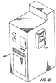
Figure 1D is an isometric view of the receptacle ofFigure 1A mounted to an object. -
Figure 2A is a cross-sectional view of an apparatus for making the receptacle ofFigures 1A-D . -
Figure 2B is a cross-sectional view of the apparatus ofFigure 2B showing the punching mechanism. -
Figure 3A is a cross-sectional view of the apparatus ofFigures 2A-2B with a perpendicular side surface when in a first position. -
Figure 3B is an isometric view in partial cross-section of the apparatus ofFigure 3A showing the actuator in-line with the punch. -
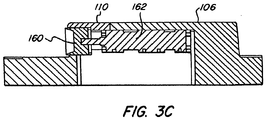
Figure 3C is a cross-sectional view of the apparatus ofFigure 3B . -
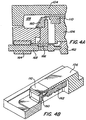
Figure 4A is a cross-sectional view of the apparatus ofFigures 3A-C when in a second position. -
Figure 4B is an isometric view in partial cross-section of the apparatus ofFigure 4A showing the actuator in-line with the punch. -
Figure 4C is a cross-sectional view of the apparatus ofFigure 4B . -
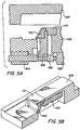
Figure 5A is a cross-sectional view of the apparatus ofFigures 4A-C when in a third position. -
Figure 5B is an isometric view in partial cross-section of the apparatus ofFigure 5A showing the actuator in-line with the punch. -
Figure 5C is a cross-sectional view of the apparatus ofFigure 5B . - Referring first to
Figure 1A-C , a typical example of a receptacle is illustrated inFigure 1 . As used in the description, the terms "top," "bottom," "above," "below," "over," "under," "above," "beneath," "on top," "underneath," "up," "down," "upper," "lower," "front," "rear," "back," "forward" and "backward" refer to the objects referenced when in the orientation illustrated in the drawings. - The receptacle includes a blow-molded,
double wall body 22 having afirst side 24 and asecond side 26, which at least partially enclose acavity 28 therebetween. Thesecond side 26 includes an unraised portion 30 and a raisedportion 32 extending transversely from the unraised portion 30. The raisedportion 32 includes anouter wall 34 and asidewall 36. Thesidewall 26 is inclined at an angle (θ) of at least forty five degrees relative theouter wall 34, and, in certain advantageous embodiments, is substantially perpendicular thereto. Thesidewall 36 has ahole 38 therethrough, thereby exposing part of thecavity 28 such that items can be inserted in this space. - In certain advantageous embodiments, the
first side 24 has a one ormore apertures 40 adapted to receive fasteners for mounting thebody 22 to anobject 42, such as a machine or vehicle, as illustrated InFigure 1D . - A lid portion is connected to the
body 22 in order to close the receptacle and shield the contents thereof from the elements or other potentially harmful substances. According to the invention, as shown inFigure 1A , the lid portion
comprises two hingedsegments segment 54 extends down at least to sidewall 36, thereby covering the unraised portion 30,sidewall 36, andhole 38 of thesecond side 26. In other embodiments, as shown inFigure 1B-C , thedouble wall body 22 includes anend wall 56, and thus, the lid portion is simply connected thereto and, when in a closed position, extends down to atleast sidewall 36. In this way, any items that are disposed in thehole 38 and resting against the unraised portion 30 of thesecond side 26. - The basic components of one embodiment of a system for creating a double wall receptacle are illustrated in
Figures 2A-B . Amold 102 comprises afirst mold portion 104 and asecond mold portion 106, which, when located adjacent each other along aseam 108, at least partially enclose acavity 128 and form amolding surface 129. Thesecond mold portion 106 comprises a mold core having abase surface 130 and a raisedportion 132 extending upwardly from thebase surface 130. In some embodiments, thebase surface 130 extends around the raisedportion 132, thereby creating a gap 133 between theside surface 136 and themolding surface 129 around the perimeter of the raisedportion 132. The raisedportion 132 includes anouter surface 134 and aside surface 136. Theside surface 136 is inclined at an angle (θ) of at least forty five degrees relative theouter surface 134, and, in certain advantageous embodiments, is substantially perpendicular thereto. - In operation, a parison (not shown) is placed between the
mold portions cavity 128 encloses the majority of the parison, and any unnecessary portions of the parison are pinched off at theseam 108 between the twomold portions molding surface 129, thereby molding the parison into the shape of the receptacle, and theside surface 136 causes the formation of theinner sidewall 36 on the receptacle. The pressure is maintained until the molten material cools and hardens, during which time apunch 160 is employed to create thehole 38 in thesidewall 36, as is further explained below. The first andsecond mold portions mold 102, and any excess flash resulting from the parison being pinched off is cut or broken away from the container receptacle. - As noted above and illustrated in
Figures 3A-C , themold 102 includes apunch 160 for creating thehole 38 in thesidewall 36. As the walls of the molded receptacle start to cool and harden, but while they are still somewhat molten, thepunch 160 is activated, at which time, a punchingsurface 164 of thepunch 160 cuts through thesidewall 36 of the receptacle enters thecavity 28. The punch is displaced by anactuator 162, which, in certain advantageous embodiments, is a fluid cylinder. Thecylinder 162 displaces thepunch 160 at an angle (Φ) of at least forty five degrees relative to theouter surface 134 of themold core 106, which depends, at least on part, on the angle (θ) of theside surface 136. In certain advantageous embodiments, when the side surface 136 (and consequently, the sidewall 36) are substantially perpendicular to theseam 108, thecylinder 162 displaces thepunch 160 in a direction substantially parallel to theseam 108. In some embodiments, acore cap 110 is positioned over the punch to cover the space created by the stroking motion of thepunch 160. - In some embodiments, as shown in
Figures 3B-C , thecylinder 162 is located within the raisedportion 134 and in-line with thepunch 160. However, in other embodiments, due to space constraints, theactuating mechanism 162 is offset from thepunch 160, and is mounted underneath themold core 106. As illustrated inFigure 3A , this is accomplished by connecting thecylinder 162 and alinear bearing 164 to themold core 106. Ashaft 166 is connected to thecylinder 162 and disposed in thebearing 164 such that actuating thecylinder 162 displaces theshaft 166 longitudinally through thebearing block 164. A mountingbar 168 is provided for mounting thepunch 160 to theshaft 166, and thus, when thecylinder 168 displaces theshaft 166, thepunch 160 likewise moves in a direction parallel to theshaft 166. In this way, cylinders with large diameters and longer lengths may be used to obtain the punching force necessary to overcome shrinkage of the blow molded walls about thepunch 160 or otherwise necessary to punch through certain plastic resins. Similarly, because the diameter of thecylinder 162 is no longer of any concern, the position of thepunch 160 is not limited, and the punch can be placed near the top of the raisedportion 132. Finally, the cylinder may be further supported by a reinforced mounting surface that may not otherwise be possible if it had to be located inside themold core 106. - The operation of the punch is illustrated in
Figures 3-5 . In the beginning of the mold cycle, after themold 102 is closed around the parison, thepunch 160 is moved into a first position, as shown inFigures 3A-C . When in this position, the punch is slightly extended into thecavity 128. For example, the punch may be extended out approximately 0.2 inches (5.1 mm) past theside surface 136. Because the cuttingsurface 164 protrudes out into thecavity 128, the plastic material thins around thesurface 164. As a result, thepunch 160 will ultimately require less force in order to punch thehole 38 therethrough. Generally, the more thepunch 160 is extended, the thinner that portion of thewall 36 will be, therefore requiring less punching force to create a hole therethrough. Additionally, because this extension of thepunch 160 effectively creates an additional, thin wall extending into thecavity 128 perpendicular to thesidewall 36, this step can also be used to provide some addition structure around the inside of thehole 38 to act as a reinforcing rib or flange. - As the walls of the blown parison began to cool and harden against the
molding surface 129, but while the plastic is still somewhat molten, thecylinder 162 is activated and rapidly moves thepunch 160 to a second position, as shown inFigure 4A-C . When in this position, thepunch 160 is extended further into the cavity 128-for example, approximately 0.5 inches (12.7 mm)-- and punches thehole 38 in thesidewall 36. - Subsequently, the
cylinder 162 moves the punch in the opposite direction, and retracts thepunch 160 back towards the raisedportion 134 of themold core 106 such that the punchingsurface 164 is fully retracted within the raisedportion 134 and does not protrude out past thesidewall 36. As a result, when themold 102 is opened, the receptacle can be easily removed without interference from any part of thepunch 160. - It should be understood that the foregoing is illustrative and not limiting, and that obvious modifications may be made by those skilled in the art. Accordingly, regarding the extent of protection, reference should be made primarily to the accompanying claims, rather than the foregoing specification.
Claims (6)
- A blow molded receptacle, comprising:a double wall, blow molded body (22), said body (22) having first and second sides (24, 26) at least partially enclosing a cavity (28) therebetween; anda lid portion integrally formed with said body (22)wherein said second side (26) includes an unraised portion (30) and a raised portion (32) extending transversely from said unraised portion (30), said raised portion (32) having an outer wall (34) and a sidewall (36), such that said cavity (28) is wider between said outer wall (34) and said first side (24) than between said unraised portion (30) and said first side (24); andwherein said sidewall (36) has a hole (38) therethrough;characterised in that said lid portion comprises first and second hinged segments (52, 54) for closing the top and side of the receptacle, respectively,wherein when the lid portion is in a closed position, the second hinged segment(54) extends down at leastto the sidewall (36), thereby covering the unraised portion (30), the sidewall (36), and the hole (38) of the second side (26).
- The receptacle of claim 1, wherein said hole (38) is a punched hole.
- The receptacle of claim 1, wherein said sidewall (36) is inclined at least forty five degrees relative to said outer wall (34).
- The receptacle of claim 3, wherein said sidewall (36) is substantially perpendicular to said outer wall (34).
- The receptacle of claim 1, wherein said first side (24) has at least one aperture (40) adapted to receive a fastener for mounting said receptacle to an object (42).
- The receptacle of claim 1, wherein:said first segment (52) of said lid portion is integrally formed with said first side (24) of said body (22); andsaid second segment(54) of said lid portion is integrally formed with said first segment (52).
Applications Claiming Priority (1)
| Application Number | Priority Date | Filing Date | Title |
|---|---|---|---|
| US11/245,603 US8283007B2 (en) | 2005-10-07 | 2005-10-07 | Blow molded receptacle and system for making same |
Publications (3)
| Publication Number | Publication Date |
|---|---|
| EP1772252A2 EP1772252A2 (en) | 2007-04-11 |
| EP1772252A3 EP1772252A3 (en) | 2014-07-09 |
| EP1772252B1 true EP1772252B1 (en) | 2020-07-01 |
Family
ID=37591499
Family Applications (1)
| Application Number | Title | Priority Date | Filing Date |
|---|---|---|---|
| EP06291562.4A Active EP1772252B1 (en) | 2005-10-07 | 2006-10-06 | Blow molded receptacle containing a hole |
Country Status (4)
| Country | Link |
|---|---|
| US (1) | US8283007B2 (en) |
| EP (1) | EP1772252B1 (en) |
| CN (1) | CN101011857B (en) |
| CA (1) | CA2562630C (en) |
Citations (2)
| Publication number | Priority date | Publication date | Assignee | Title |
|---|---|---|---|---|
| US3902628A (en) * | 1972-09-13 | 1975-09-02 | Plastic Forming Company Inc | Plastic container hinge and latch |
| US6083579A (en) * | 1993-12-07 | 2000-07-04 | The Plastic Forming Company, Inc. | Blow molded article |
Family Cites Families (9)
| Publication number | Priority date | Publication date | Assignee | Title |
|---|---|---|---|---|
| US1090846A (en) * | 1913-04-29 | 1914-03-24 | Paul Greindl | Automatic cashier. |
| US3327841A (en) * | 1964-09-09 | 1967-06-27 | Grace W R & Co | Plastic container |
| US5382515A (en) * | 1987-07-21 | 1995-01-17 | International Immunoassay Laboratories, Inc. | Creative kinase-MB immunoassay for myocardial infarction and reagents |
| DE3913087A1 (en) * | 1989-04-21 | 1990-10-25 | Mauser Werke Gmbh | DEVICE FOR BLOW MOLDING A HOLLOW BODY |
| US5429240A (en) * | 1992-12-30 | 1995-07-04 | Minnesota Mining And Manufacturing Company | Light-tight container |
| US6348173B1 (en) | 1999-01-21 | 2002-02-19 | Custom-Pak, Inc. | Core pulls concentric with ejector pins |
| US6662114B1 (en) * | 1999-08-23 | 2003-12-09 | Duke University | Methods for evaluating therapies and predicting clinical outcome related to coronary conditions |
| US20030104098A1 (en) * | 2001-11-30 | 2003-06-05 | Brent Schrader | Formation of punched, blind holes through one wall of a double wall blow molded structure |
| US7021920B2 (en) * | 2001-11-30 | 2006-04-04 | Custom-Pak, Inc | Method and apparatus for blow molding a bottle with a punched hole in a molded neck recess |
-
2005
- 2005-10-07 US US11/245,603 patent/US8283007B2/en active Active
-
2006
- 2006-10-05 CA CA2562630A patent/CA2562630C/en active Active
- 2006-10-06 EP EP06291562.4A patent/EP1772252B1/en active Active
- 2006-10-08 CN CN2006100644108A patent/CN101011857B/en not_active Expired - Fee Related
Patent Citations (2)
| Publication number | Priority date | Publication date | Assignee | Title |
|---|---|---|---|---|
| US3902628A (en) * | 1972-09-13 | 1975-09-02 | Plastic Forming Company Inc | Plastic container hinge and latch |
| US6083579A (en) * | 1993-12-07 | 2000-07-04 | The Plastic Forming Company, Inc. | Blow molded article |
Also Published As
| Publication number | Publication date |
|---|---|
| CN101011857A (en) | 2007-08-08 |
| CA2562630A1 (en) | 2007-04-07 |
| US8283007B2 (en) | 2012-10-09 |
| EP1772252A2 (en) | 2007-04-11 |
| US20070082153A1 (en) | 2007-04-12 |
| CA2562630C (en) | 2010-12-14 |
| EP1772252A3 (en) | 2014-07-09 |
| CN101011857B (en) | 2010-05-26 |
Similar Documents
| Publication | Publication Date | Title |
|---|---|---|
| KR101004978B1 (en) | Mold for manufacturing an extruded blow molded article with an insert on the inside | |
| US20080111285A1 (en) | Blow Molded Case and Method and Apparatus for Creating Same | |
| US7993127B2 (en) | Blow molding device | |
| EP3272492B1 (en) | Blow-mold unit and blow molding device using same | |
| US20100092593A1 (en) | Blow molding device | |
| US7727455B2 (en) | Apparatus and method for creation of a blow molded container having holes therein | |
| US6808674B1 (en) | Enclosed area on a blow molded article and method of making the same | |
| DE102010025937A1 (en) | Process for producing a plastic article and blow molding tool for carrying out the process | |
| US8283007B2 (en) | Blow molded receptacle and system for making same | |
| US9962880B2 (en) | Blow molding device and blow molding method | |
| US9289940B2 (en) | Method and apparatus for in-mold finishing of blow molded parts | |
| JP3618700B2 (en) | Injection mold | |
| KR20230132882A (en) | Molding production method, molding die and molding line | |
| JP2003181908A (en) | Deep drawing blow molded fuel tank, mold and molding method thereof | |
| CN101157271A (en) | Power device and method for forming blow molded articles | |
| CN117615926A (en) | fuel tank | |
| KR102456985B1 (en) | Mold for blow molding, method for manufacturing a resin container using the same, and a resin container | |
| JPH0675917B2 (en) | Hollow molding device for articles with bent parts | |
| JP4664105B2 (en) | Molding apparatus and molding method | |
| JP2002225120A (en) | Method and apparatus for blow-molding three- dimensionally bent product | |
| JP5061894B2 (en) | Mold equipment | |
| JPH07148792A (en) | Injection mold | |
| JP2002172684A (en) | Unnecessary part in-mold cutting method for hollow molded products | |
| JP2017019175A (en) | Molding method having characteristic in ejection of molded product and injection molding machine | |
| CN118181654A (en) | Injection mold |
Legal Events
| Date | Code | Title | Description |
|---|---|---|---|
| PUAI | Public reference made under article 153(3) epc to a published international application that has entered the european phase |
Free format text: ORIGINAL CODE: 0009012 |
|
| AK | Designated contracting states |
Kind code of ref document: A2 Designated state(s): AT BE BG CH CY CZ DE DK EE ES FI FR GB GR HU IE IS IT LI LT LU LV MC NL PL PT RO SE SI SK TR |
|
| AX | Request for extension of the european patent |
Extension state: AL BA HR MK YU |
|
| 17P | Request for examination filed |
Effective date: 20070511 |
|
| RIC1 | Information provided on ipc code assigned before grant |
Ipc: B29C 49/50 20060101AFI20131113BHEP Ipc: B29C 49/04 20060101ALN20131113BHEP Ipc: B42F 7/14 20060101ALI20131113BHEP Ipc: B29C 49/48 20060101ALN20131113BHEP |
|
| PUAL | Search report despatched |
Free format text: ORIGINAL CODE: 0009013 |
|
| AK | Designated contracting states |
Kind code of ref document: A3 Designated state(s): AT BE BG CH CY CZ DE DK EE ES FI FR GB GR HU IE IS IT LI LT LU LV MC NL PL PT RO SE SI SK TR |
|
| AX | Request for extension of the european patent |
Extension state: AL BA HR MK RS |
|
| RIC1 | Information provided on ipc code assigned before grant |
Ipc: B42F 7/14 20060101ALI20140605BHEP Ipc: B29C 49/48 20060101ALN20140605BHEP Ipc: B29C 49/04 20060101ALN20140605BHEP Ipc: B29C 49/50 20060101AFI20140605BHEP |
|
| AKX | Designation fees paid |
Designated state(s): AT BE BG CH CY CZ DE DK EE ES FI FR GB GR HU IE IS IT LI LT LU LV MC NL PL PT RO SE SI SK TR |
|
| AXX | Extension fees paid |
Extension state: MK Extension state: AL Extension state: BA Extension state: RS Extension state: HR |
|
| STAA | Information on the status of an ep patent application or granted ep patent |
Free format text: STATUS: EXAMINATION IS IN PROGRESS |
|
| 17Q | First examination report despatched |
Effective date: 20180306 |
|
| GRAP | Despatch of communication of intention to grant a patent |
Free format text: ORIGINAL CODE: EPIDOSNIGR1 |
|
| STAA | Information on the status of an ep patent application or granted ep patent |
Free format text: STATUS: GRANT OF PATENT IS INTENDED |
|
| RIC1 | Information provided on ipc code assigned before grant |
Ipc: B29C 49/48 20060101ALN20191209BHEP Ipc: B42F 7/14 20060101ALI20191209BHEP Ipc: B29C 49/04 20060101ALN20191209BHEP Ipc: B29C 49/50 20060101AFI20191209BHEP |
|
| RIC1 | Information provided on ipc code assigned before grant |
Ipc: B29C 49/50 20060101AFI20191218BHEP Ipc: B29C 49/04 20060101ALN20191218BHEP Ipc: B42F 7/14 20060101ALI20191218BHEP Ipc: B29C 49/48 20060101ALN20191218BHEP |
|
| INTG | Intention to grant announced |
Effective date: 20200113 |
|
| GRAS | Grant fee paid |
Free format text: ORIGINAL CODE: EPIDOSNIGR3 |
|
| GRAA | (expected) grant |
Free format text: ORIGINAL CODE: 0009210 |
|
| STAA | Information on the status of an ep patent application or granted ep patent |
Free format text: STATUS: THE PATENT HAS BEEN GRANTED |
|
| REG | Reference to a national code |
Ref country code: DE Ref legal event code: R081 Ref document number: 602006059520 Country of ref document: DE Owner name: CUSTOM-PAK, INC., CLINTON, US Free format text: FORMER OWNER: CUSTOM-PAK, INC., CLINTON, IA., US |
|
| AK | Designated contracting states |
Kind code of ref document: B1 Designated state(s): AT BE BG CH CY CZ DE DK EE ES FI FR GB GR HU IE IS IT LI LT LU LV MC NL PL PT RO SE SI SK TR |
|
| REG | Reference to a national code |
Ref country code: GB Ref legal event code: FG4D |
|
| REG | Reference to a national code |
Ref country code: CH Ref legal event code: EP Ref country code: AT Ref legal event code: REF Ref document number: 1285756 Country of ref document: AT Kind code of ref document: T Effective date: 20200715 |
|
| REG | Reference to a national code |
Ref country code: IE Ref legal event code: FG4D |
|
| REG | Reference to a national code |
Ref country code: DE Ref legal event code: R096 Ref document number: 602006059520 Country of ref document: DE |
|
| REG | Reference to a national code |
Ref country code: LT Ref legal event code: MG4D |
|
| PG25 | Lapsed in a contracting state [announced via postgrant information from national office to epo] |
Ref country code: BG Free format text: LAPSE BECAUSE OF FAILURE TO SUBMIT A TRANSLATION OF THE DESCRIPTION OR TO PAY THE FEE WITHIN THE PRESCRIBED TIME-LIMIT Effective date: 20201001 |
|
| REG | Reference to a national code |
Ref country code: NL Ref legal event code: MP Effective date: 20200701 |
|
| REG | Reference to a national code |
Ref country code: AT Ref legal event code: MK05 Ref document number: 1285756 Country of ref document: AT Kind code of ref document: T Effective date: 20200701 |
|
| PG25 | Lapsed in a contracting state [announced via postgrant information from national office to epo] |
Ref country code: AT Free format text: LAPSE BECAUSE OF FAILURE TO SUBMIT A TRANSLATION OF THE DESCRIPTION OR TO PAY THE FEE WITHIN THE PRESCRIBED TIME-LIMIT Effective date: 20200701 Ref country code: LT Free format text: LAPSE BECAUSE OF FAILURE TO SUBMIT A TRANSLATION OF THE DESCRIPTION OR TO PAY THE FEE WITHIN THE PRESCRIBED TIME-LIMIT Effective date: 20200701 Ref country code: GR Free format text: LAPSE BECAUSE OF FAILURE TO SUBMIT A TRANSLATION OF THE DESCRIPTION OR TO PAY THE FEE WITHIN THE PRESCRIBED TIME-LIMIT Effective date: 20201002 Ref country code: FI Free format text: LAPSE BECAUSE OF FAILURE TO SUBMIT A TRANSLATION OF THE DESCRIPTION OR TO PAY THE FEE WITHIN THE PRESCRIBED TIME-LIMIT Effective date: 20200701 Ref country code: SE Free format text: LAPSE BECAUSE OF FAILURE TO SUBMIT A TRANSLATION OF THE DESCRIPTION OR TO PAY THE FEE WITHIN THE PRESCRIBED TIME-LIMIT Effective date: 20200701 Ref country code: CZ Free format text: LAPSE BECAUSE OF FAILURE TO SUBMIT A TRANSLATION OF THE DESCRIPTION OR TO PAY THE FEE WITHIN THE PRESCRIBED TIME-LIMIT Effective date: 20200701 Ref country code: ES Free format text: LAPSE BECAUSE OF FAILURE TO SUBMIT A TRANSLATION OF THE DESCRIPTION OR TO PAY THE FEE WITHIN THE PRESCRIBED TIME-LIMIT Effective date: 20200701 Ref country code: PT Free format text: LAPSE BECAUSE OF FAILURE TO SUBMIT A TRANSLATION OF THE DESCRIPTION OR TO PAY THE FEE WITHIN THE PRESCRIBED TIME-LIMIT Effective date: 20201102 |
|
| PG25 | Lapsed in a contracting state [announced via postgrant information from national office to epo] |
Ref country code: LV Free format text: LAPSE BECAUSE OF FAILURE TO SUBMIT A TRANSLATION OF THE DESCRIPTION OR TO PAY THE FEE WITHIN THE PRESCRIBED TIME-LIMIT Effective date: 20200701 Ref country code: PL Free format text: LAPSE BECAUSE OF FAILURE TO SUBMIT A TRANSLATION OF THE DESCRIPTION OR TO PAY THE FEE WITHIN THE PRESCRIBED TIME-LIMIT Effective date: 20200701 Ref country code: IS Free format text: LAPSE BECAUSE OF FAILURE TO SUBMIT A TRANSLATION OF THE DESCRIPTION OR TO PAY THE FEE WITHIN THE PRESCRIBED TIME-LIMIT Effective date: 20201101 |
|
| PG25 | Lapsed in a contracting state [announced via postgrant information from national office to epo] |
Ref country code: NL Free format text: LAPSE BECAUSE OF FAILURE TO SUBMIT A TRANSLATION OF THE DESCRIPTION OR TO PAY THE FEE WITHIN THE PRESCRIBED TIME-LIMIT Effective date: 20200701 |
|
| REG | Reference to a national code |
Ref country code: DE Ref legal event code: R097 Ref document number: 602006059520 Country of ref document: DE |
|
| PG25 | Lapsed in a contracting state [announced via postgrant information from national office to epo] |
Ref country code: DK Free format text: LAPSE BECAUSE OF FAILURE TO SUBMIT A TRANSLATION OF THE DESCRIPTION OR TO PAY THE FEE WITHIN THE PRESCRIBED TIME-LIMIT Effective date: 20200701 Ref country code: EE Free format text: LAPSE BECAUSE OF FAILURE TO SUBMIT A TRANSLATION OF THE DESCRIPTION OR TO PAY THE FEE WITHIN THE PRESCRIBED TIME-LIMIT Effective date: 20200701 Ref country code: IT Free format text: LAPSE BECAUSE OF FAILURE TO SUBMIT A TRANSLATION OF THE DESCRIPTION OR TO PAY THE FEE WITHIN THE PRESCRIBED TIME-LIMIT Effective date: 20200701 Ref country code: RO Free format text: LAPSE BECAUSE OF FAILURE TO SUBMIT A TRANSLATION OF THE DESCRIPTION OR TO PAY THE FEE WITHIN THE PRESCRIBED TIME-LIMIT Effective date: 20200701 |
|
| PLBE | No opposition filed within time limit |
Free format text: ORIGINAL CODE: 0009261 |
|
| STAA | Information on the status of an ep patent application or granted ep patent |
Free format text: STATUS: NO OPPOSITION FILED WITHIN TIME LIMIT |
|
| REG | Reference to a national code |
Ref country code: CH Ref legal event code: PL |
|
| 26N | No opposition filed |
Effective date: 20210406 |
|
| PG25 | Lapsed in a contracting state [announced via postgrant information from national office to epo] |
Ref country code: LU Free format text: LAPSE BECAUSE OF NON-PAYMENT OF DUE FEES Effective date: 20201006 Ref country code: SK Free format text: LAPSE BECAUSE OF FAILURE TO SUBMIT A TRANSLATION OF THE DESCRIPTION OR TO PAY THE FEE WITHIN THE PRESCRIBED TIME-LIMIT Effective date: 20200701 Ref country code: MC Free format text: LAPSE BECAUSE OF FAILURE TO SUBMIT A TRANSLATION OF THE DESCRIPTION OR TO PAY THE FEE WITHIN THE PRESCRIBED TIME-LIMIT Effective date: 20200701 |
|
| REG | Reference to a national code |
Ref country code: BE Ref legal event code: MM Effective date: 20201031 |
|
| PG25 | Lapsed in a contracting state [announced via postgrant information from national office to epo] |
Ref country code: CH Free format text: LAPSE BECAUSE OF NON-PAYMENT OF DUE FEES Effective date: 20201031 Ref country code: BE Free format text: LAPSE BECAUSE OF NON-PAYMENT OF DUE FEES Effective date: 20201031 Ref country code: SI Free format text: LAPSE BECAUSE OF FAILURE TO SUBMIT A TRANSLATION OF THE DESCRIPTION OR TO PAY THE FEE WITHIN THE PRESCRIBED TIME-LIMIT Effective date: 20200701 Ref country code: LI Free format text: LAPSE BECAUSE OF NON-PAYMENT OF DUE FEES Effective date: 20201031 |
|
| PG25 | Lapsed in a contracting state [announced via postgrant information from national office to epo] |
Ref country code: IE Free format text: LAPSE BECAUSE OF NON-PAYMENT OF DUE FEES Effective date: 20201006 |
|
| PG25 | Lapsed in a contracting state [announced via postgrant information from national office to epo] |
Ref country code: TR Free format text: LAPSE BECAUSE OF FAILURE TO SUBMIT A TRANSLATION OF THE DESCRIPTION OR TO PAY THE FEE WITHIN THE PRESCRIBED TIME-LIMIT Effective date: 20200701 Ref country code: CY Free format text: LAPSE BECAUSE OF FAILURE TO SUBMIT A TRANSLATION OF THE DESCRIPTION OR TO PAY THE FEE WITHIN THE PRESCRIBED TIME-LIMIT Effective date: 20200701 |
|
| P01 | Opt-out of the competence of the unified patent court (upc) registered |
Effective date: 20230530 |
|
| PGFP | Annual fee paid to national office [announced via postgrant information from national office to epo] |
Ref country code: GB Payment date: 20230927 Year of fee payment: 18 |
|
| PGFP | Annual fee paid to national office [announced via postgrant information from national office to epo] |
Ref country code: FR Payment date: 20240821 Year of fee payment: 19 |
|
| PGFP | Annual fee paid to national office [announced via postgrant information from national office to epo] |
Ref country code: DE Payment date: 20240820 Year of fee payment: 19 |
|
| GBPC | Gb: european patent ceased through non-payment of renewal fee |
Effective date: 20241006 |
|
| PG25 | Lapsed in a contracting state [announced via postgrant information from national office to epo] |
Ref country code: GB Free format text: LAPSE BECAUSE OF NON-PAYMENT OF DUE FEES Effective date: 20241006 |