EP1772161A1 - Peritoneal dialysis catheters - Google Patents
Peritoneal dialysis catheters Download PDFInfo
- Publication number
- EP1772161A1 EP1772161A1 EP06077310A EP06077310A EP1772161A1 EP 1772161 A1 EP1772161 A1 EP 1772161A1 EP 06077310 A EP06077310 A EP 06077310A EP 06077310 A EP06077310 A EP 06077310A EP 1772161 A1 EP1772161 A1 EP 1772161A1
- Authority
- EP
- European Patent Office
- Prior art keywords
- patient
- catheter
- lumen
- section
- fluid
- Prior art date
- Legal status (The legal status is an assumption and is not a legal conclusion. Google has not performed a legal analysis and makes no representation as to the accuracy of the status listed.)
- Granted
Links
- 238000000502 dialysis Methods 0.000 title claims abstract description 90
- 210000003200 peritoneal cavity Anatomy 0.000 claims abstract description 46
- 239000012530 fluid Substances 0.000 claims description 77
- 238000000926 separation method Methods 0.000 claims description 28
- 238000000034 method Methods 0.000 claims description 15
- 239000007943 implant Substances 0.000 claims description 8
- 230000007704 transition Effects 0.000 claims description 6
- 210000003205 muscle Anatomy 0.000 claims description 4
- 238000007920 subcutaneous administration Methods 0.000 claims description 3
- 230000009977 dual effect Effects 0.000 abstract description 10
- 238000002156 mixing Methods 0.000 abstract description 7
- GDTHVMAIBQVUMV-UHFFFAOYSA-N 2-oxopentanal Chemical compound CCCC(=O)C=O GDTHVMAIBQVUMV-UHFFFAOYSA-N 0.000 abstract 1
- 239000003053 toxin Substances 0.000 description 10
- 231100000765 toxin Toxicity 0.000 description 10
- 108700012359 toxins Proteins 0.000 description 10
- XLYOFNOQVPJJNP-UHFFFAOYSA-N water Substances O XLYOFNOQVPJJNP-UHFFFAOYSA-N 0.000 description 10
- 238000002513 implantation Methods 0.000 description 9
- 210000004379 membrane Anatomy 0.000 description 9
- 239000012528 membrane Substances 0.000 description 9
- 239000002699 waste material Substances 0.000 description 9
- 230000006870 function Effects 0.000 description 5
- 238000001631 haemodialysis Methods 0.000 description 5
- 230000000322 hemodialysis Effects 0.000 description 5
- 239000008280 blood Substances 0.000 description 4
- 210000004369 blood Anatomy 0.000 description 4
- 210000004197 pelvis Anatomy 0.000 description 4
- 210000004303 peritoneum Anatomy 0.000 description 4
- 238000012546 transfer Methods 0.000 description 4
- 206010059017 Intestinal mass Diseases 0.000 description 3
- 210000003815 abdominal wall Anatomy 0.000 description 3
- 230000008901 benefit Effects 0.000 description 3
- 238000002224 dissection Methods 0.000 description 3
- 238000003780 insertion Methods 0.000 description 3
- 230000037431 insertion Effects 0.000 description 3
- 210000003734 kidney Anatomy 0.000 description 3
- 230000003907 kidney function Effects 0.000 description 3
- 238000012986 modification Methods 0.000 description 3
- 230000004048 modification Effects 0.000 description 3
- 239000000243 solution Substances 0.000 description 3
- 210000001519 tissue Anatomy 0.000 description 3
- FAPWRFPIFSIZLT-UHFFFAOYSA-M Sodium chloride Chemical compound [Na+].[Cl-] FAPWRFPIFSIZLT-UHFFFAOYSA-M 0.000 description 2
- 208000027418 Wounds and injury Diseases 0.000 description 2
- 210000004185 liver Anatomy 0.000 description 2
- 206010033675 panniculitis Diseases 0.000 description 2
- 238000002360 preparation method Methods 0.000 description 2
- 210000004304 subcutaneous tissue Anatomy 0.000 description 2
- 238000002560 therapeutic procedure Methods 0.000 description 2
- 230000005641 tunneling Effects 0.000 description 2
- CPKVUHPKYQGHMW-UHFFFAOYSA-N 1-ethenylpyrrolidin-2-one;molecular iodine Chemical compound II.C=CN1CCCC1=O CPKVUHPKYQGHMW-UHFFFAOYSA-N 0.000 description 1
- 241000792859 Enema Species 0.000 description 1
- 208000001647 Renal Insufficiency Diseases 0.000 description 1
- 210000001015 abdomen Anatomy 0.000 description 1
- 238000012084 abdominal surgery Methods 0.000 description 1
- 238000004873 anchoring Methods 0.000 description 1
- 230000003466 anti-cipated effect Effects 0.000 description 1
- 210000001367 artery Anatomy 0.000 description 1
- 230000009286 beneficial effect Effects 0.000 description 1
- 229940064804 betadine Drugs 0.000 description 1
- 230000017531 blood circulation Effects 0.000 description 1
- 230000008859 change Effects 0.000 description 1
- 238000002591 computed tomography Methods 0.000 description 1
- 230000006378 damage Effects 0.000 description 1
- 239000000385 dialysis solution Substances 0.000 description 1
- 238000009792 diffusion process Methods 0.000 description 1
- 239000007920 enema Substances 0.000 description 1
- 229940095399 enema Drugs 0.000 description 1
- 210000003195 fascia Anatomy 0.000 description 1
- 238000001914 filtration Methods 0.000 description 1
- 238000002695 general anesthesia Methods 0.000 description 1
- 238000003384 imaging method Methods 0.000 description 1
- 208000014674 injury Diseases 0.000 description 1
- 238000007912 intraperitoneal administration Methods 0.000 description 1
- 201000006370 kidney failure Diseases 0.000 description 1
- 239000000463 material Substances 0.000 description 1
- 230000005012 migration Effects 0.000 description 1
- 238000013508 migration Methods 0.000 description 1
- 210000001087 myotubule Anatomy 0.000 description 1
- 210000000505 parietal peritoneum Anatomy 0.000 description 1
- 229920000728 polyester Polymers 0.000 description 1
- 230000008569 process Effects 0.000 description 1
- 230000007958 sleep Effects 0.000 description 1
- 239000011780 sodium chloride Substances 0.000 description 1
- 210000000952 spleen Anatomy 0.000 description 1
- 210000003462 vein Anatomy 0.000 description 1
Images



Classifications
-
- A—HUMAN NECESSITIES
- A61—MEDICAL OR VETERINARY SCIENCE; HYGIENE
- A61M—DEVICES FOR INTRODUCING MEDIA INTO, OR ONTO, THE BODY; DEVICES FOR TRANSDUCING BODY MEDIA OR FOR TAKING MEDIA FROM THE BODY; DEVICES FOR PRODUCING OR ENDING SLEEP OR STUPOR
- A61M1/00—Suction or pumping devices for medical purposes; Devices for carrying-off, for treatment of, or for carrying-over, body-liquids; Drainage systems
- A61M1/14—Dialysis systems; Artificial kidneys; Blood oxygenators ; Reciprocating systems for treatment of body fluids, e.g. single needle systems for hemofiltration or pheresis
- A61M1/28—Peritoneal dialysis ; Other peritoneal treatment, e.g. oxygenation
- A61M1/285—Catheters therefor
-
- A—HUMAN NECESSITIES
- A61—MEDICAL OR VETERINARY SCIENCE; HYGIENE
- A61M—DEVICES FOR INTRODUCING MEDIA INTO, OR ONTO, THE BODY; DEVICES FOR TRANSDUCING BODY MEDIA OR FOR TAKING MEDIA FROM THE BODY; DEVICES FOR PRODUCING OR ENDING SLEEP OR STUPOR
- A61M25/00—Catheters; Hollow probes
-
- A—HUMAN NECESSITIES
- A61—MEDICAL OR VETERINARY SCIENCE; HYGIENE
- A61M—DEVICES FOR INTRODUCING MEDIA INTO, OR ONTO, THE BODY; DEVICES FOR TRANSDUCING BODY MEDIA OR FOR TAKING MEDIA FROM THE BODY; DEVICES FOR PRODUCING OR ENDING SLEEP OR STUPOR
- A61M1/00—Suction or pumping devices for medical purposes; Devices for carrying-off, for treatment of, or for carrying-over, body-liquids; Drainage systems
- A61M1/14—Dialysis systems; Artificial kidneys; Blood oxygenators ; Reciprocating systems for treatment of body fluids, e.g. single needle systems for hemofiltration or pheresis
- A61M1/28—Peritoneal dialysis ; Other peritoneal treatment, e.g. oxygenation
- A61M1/282—Operational modes
- A61M1/284—Continuous flow peritoneal dialysis [CFPD]
-
- A—HUMAN NECESSITIES
- A61—MEDICAL OR VETERINARY SCIENCE; HYGIENE
- A61M—DEVICES FOR INTRODUCING MEDIA INTO, OR ONTO, THE BODY; DEVICES FOR TRANSDUCING BODY MEDIA OR FOR TAKING MEDIA FROM THE BODY; DEVICES FOR PRODUCING OR ENDING SLEEP OR STUPOR
- A61M25/00—Catheters; Hollow probes
- A61M25/0021—Catheters; Hollow probes characterised by the form of the tubing
- A61M25/0041—Catheters; Hollow probes characterised by the form of the tubing pre-formed, e.g. specially adapted to fit with the anatomy of body channels
-
- A—HUMAN NECESSITIES
- A61—MEDICAL OR VETERINARY SCIENCE; HYGIENE
- A61M—DEVICES FOR INTRODUCING MEDIA INTO, OR ONTO, THE BODY; DEVICES FOR TRANSDUCING BODY MEDIA OR FOR TAKING MEDIA FROM THE BODY; DEVICES FOR PRODUCING OR ENDING SLEEP OR STUPOR
- A61M25/00—Catheters; Hollow probes
- A61M25/01—Introducing, guiding, advancing, emplacing or holding catheters
- A61M25/02—Holding devices, e.g. on the body
- A61M2025/0293—Catheter, guide wire or the like with means for holding, centering, anchoring or frictionally engaging the device within an artificial lumen, e.g. tube
Definitions
- the present invention generally relates to catheters, and more specifically, the present invention relates to dual lumen catheters having two fluid flow paths.
- the catheters can be used for peritoneal dialysis to infuse and remove dialysate simultaneously into and from a patient.
- the present invention also relates to methods of implanting and using catheters.
- Kidney failure and reduced kidney function have been treated with dialysis. Dialysis removes waste, toxins, and excess water from the body that would otherwise have been removed by normal functioning kidneys. Dialysis treatment for replacement of kidney functions is critical to many people because the treatment is life saving. One who has failed kidneys could not continue to live without replacing at least the filtration functions of the kidneys.
- Hemodialysis and peritoneal dialysis are two types of dialysis commonly used to treat loss of kidney function.
- Hemodialysis treatment utilizes the patient's blood to remove waste, toxins, and excess water from the patient.
- the patient is connected to a hemodialysis machine and the patient's blood is pumped through the machine.
- Catheters are inserted into the patient's veins and arteries to connect the bloodflow to and from the hemodialysis machine.
- the waste, toxins, and excess water are removed from the patient's blood and the blood is infused back into the patient.
- Hemodialysis treatment lasts several hours and is generally performed in a treatment center about three or four times per week.
- Peritoneal dialysis utilizes a dialysis solution and dialysate, which is infused into a patient's peritoneal cavity.
- the dialysate contacts the patient's peritoneal membrane in the peritoneal cavity. Waste, toxins, and excess water pass from the patient's bloodstream through the peritoneal membrane and into the dialysate. The transfer of waste, toxins, and water from the bloodstream into the dialysate occurs due to diffusion and osmosis.
- the spent dialysate is drained from the patient's peritoneal cavity to remove the waste, toxins, and water from the patient and replaced.
- Peritoneal dialysis catheters are used to transfer the fresh dialysate into the peritoneal cavity and remove spent dialysate from the cavity.
- a peritoneal catheter is implanted into the peritoneal cavity and remains implanted for an extended period oftime.
- the average catheter may remain implanted for about 18-24 months, but it is not unusual for a catheter to remain indwell for more than 2 years.
- CAPD continuous ambulatory peritoneal dialysis
- automated peritoneal dialysis CAPD is a manual dialysis treatment in which the patient connects the implanted catheter to a drain and allows spent dialysate fluid to drain from the peritoneal cavity. The patient then connects to a bag of fresh dialysate and manually infuses the fresh dialysate through the catheter and into the patient's peritoneal cavity. The patient disconnects the catheter from the fresh dialysate bag and allows the dialysate to dwell within the cavity to transfer waste, toxins, and excess water from the patient's bloodstream to the dialysate solution. After the dwell period, the patient repeats the manual dialysis procedure.
- the patient performs several drain, fill, and dwell cycles during the day, for example, about four times per day. Each treatment cycle typically takes about 3-4 hours. Manual peritoneal dialysis performed by the patient requires quite a lot of time and effort by the patient. The patient is routinely inconvenienced leaving ample opportunity for therapy enhancements to improve patient quality of life.
- Automated peritoneal dialysis is similar to continuous peritoneal dialysis in that the dialysis treatment includes a drain, fill, and dwell cycle. However, a dialysis machine automatically performs 3-4 cycles of peritoneal dialysis treatment, typically overnight while the patient sleeps.
- a dialysis machine is fluidly connected to the implanted catheter.
- the dialysis machine is also fluidly connected to a source of fresh dialysate, such as a bag of dialysate solution, and to a fluid drain.
- the dialysis machine pumps spent dialysate from the peritoneal cavity through the catheter to the drain. Then, the dialysis machine pumps fresh dialysate from the dialysate source through the catheter and into the patient's peritoneal cavity.
- the dialysis machine allows the dialysate to dwell within the cavity to transfer waste, toxins, and excess water from the patient's bloodstream to the dialysate solution.
- the dialysis machine is computer controlled so that the dialysis treatment occurs automatically when the patient is connected to the dialysis machine, for example, overnight. Several drain, fill, and dwell cycles will occur during the treatment. Also, a last fill is typically used at the end of the automated dialysis treatment so that the patient can disconnect from the dialysis machine and continue daily functions while dialysate remains in the peritoneal cavity. Automated peritoneal dialysis frees the patient from manually performing the drain, dwell, and fill steps, and can improve the patient's dialysis treatment and quality of life.
- peritoneal catheters exist for patient implantation to perform peritoneal dialysis.
- Existing peritoneal catheters include single lumen and dual lumen catheters.
- a single lumen catheter has a single fluid passageway through the catheter, and a dual lumen catheter has two fluid passageways.
- Single lumen catheters allow fluid flow in only one direction into or out of the patient at any given moment.
- Dual lumen catheters allow fluid flow both into and out of the patient at the same time. Because catheters are surgically implanted into patients and because the catheters allow fluids to be infused into and drained from the patients, improvements to catheters and methods of implanting and using catheters can be beneficial.
- the present invention provides new catheters, particularly for continuous flow peritoneal dialysis (CFPD).
- CFPD continuous flow peritoneal dialysis
- dialysate flows continuously, i.e. simultaneously, into and out of the patient.
- the new catheters have two lumens. One lumen allows for fresh dialysate to be infused into the patient, and the other lumen allows for spent dialysate to be removed from the patient. Accordingly, fresh dialysate can flow into the patient simultaneously with spent dialysate flowing out of the patient. It is anticipated that a dialysis machine will be used to automatically perform the dialysis treatment using the new catheters.
- the new catheter delivers fresh dialysate into the peritoneal cavity at a location significantly separated from a location at which the catheter removes spent dialysate from the peritoneal cavity.
- the separation of the patient inflow and outflow locations of the catheter tends to enhance mixing of the dialysate within the peritoneal cavity.
- the dialysate may tend to contact a relatively large area of the peritoneal membrane. A situation in which the dialysate flows directly from the patient inflow location to the patient outflow location on the catheter with minimal contact of the peritoneal membrane, shunting, tends to be avoided.
- the catheter has fluid openings from the inflow lumen which are directed away from the fluid openings to the patient outflow lumen at the patient outflow location. This direction of the patient inflow fluid openings also tends to enhance dialysate mixing and minimize shunting within the peritoneal cavity.
- One catheter according to the present invention extends from a proximal end outside of the patient, upward into the patient and to a preformed bend.
- the proximal end has openings to the patient inflow and outflow lumens for connection to a dialysis machine, including a dialysate supply and drain.
- the patient inflow lumen extends from the proximal end to a patient inflow port at the preformed bend.
- the catheter continues to extend downward from the preformed bend to a distal end inside of the patient's peritoneal cavity.
- the patient outflow lumen extends from the proximal end to a patient outflow port at the distal end.
- the distal end of the catheter may have a coiled shape.
- the preformed bend is positioned in the upper area of the peritoneal cavity and the coiled distal end is positioned in the lower area of the peritoneal cavity.
- CT Scan and MRI imaging of normal peritoneal dialysis patients lying in supine position (on back) with fluid filled peritoneal cavities shows two distinct pools of fluid. One pool is found in the upper region of the cavity in the vicinity of the liver and spleen. The second pool is located in the lower pelvic region separated from the upper pool by the intestinal mass. This catheter shape was conceived to take advantage of this reality by locating the patient in flow section in the upper pool where fresh dialysate is infused directly.
- the fresh dialysate is forced to filter down through the intestinal mass to the patient outflow section strategically located in the lower pool.
- This process enhances mixing with spent dialysate and exposes a large area of the peritoneal membrane to "fresher" dialysate for improved toxin and water removal.
- the catheter shape also assists in maintaining the catheter position within the peritoneal cavity, i.e., the patient inflow preformed bend positioned high in the peritoneum and the patient outflow end positioned low in the peritoneum This can help reduce or prevent omental adhesion to the catheter due to catheter tip migration which causes catheter fluid flow obstructions.
- fluid can flow from the proximal end through the patient inflow lumen, out of the patient inflow port, and into the peritoneal cavity.
- the fluid inside the cavity contacts the peritoneal membrane, mixes with fluid in the cavity, removes waste, toxins, and water, and flows to the patient outflow port at the distal catheter end.
- the fluid then flows from the distal end through the patient outflow lumen to the catheter proximal end and is removed from the patient.
- a new catheter 10 according to the principles of the present invention is shown by way of example in Fig. 1.
- the catheter 10 is implanted into a patient's peritoneal cavity for peritoneal dialysis.
- the catheter 10 is shown partially in phantom implanted into a patient 12.
- the catheter 10 allows for dialysate to be infused into and removed out of the peritoneal cavity.
- the catheter 10 allows for continuous flow peritoneal dialysis treatment.
- continuous flow peritoneal dialysis means that dialysate flows simultaneously into and out of the peritoneal cavity.
- the catheter 10 can also be used to perform other types of peritoneal dialysis.
- the catheter 10 is a dual lumen catheter which has two lumens or fluid flow paths through a flexible tube 14.
- One lumen provides for fluid to flow from outside the patient, through the catheter 10, and into the patient, i.e. to infuse dialysate into the peritoneal cavity.
- the second lumen provides for fluid flow in the opposite direction.
- the second lumen allows fluid to flow from the peritoneal cavity, through the catheter 10, and exit the patient.
- Continuous flow peritoneal dialysis can be performed on the patient because of the dual lumens in the catheter 10.
- the catheter 10 can be used without simultaneous fluid flow into and out of the patient.
- the dialysis treatment may be controlled such that fluid flows through only one lumen at any given time.
- the catheter 10 is shown and described as a single tube 14 having multiple lumens, other structures could be used.
- the catheter 10 could be made of two single lumen tubes joined together along their longitudinal lengths.
- the catheter 10 is made of flexible medical grade tubing 14 suitable for implanting inside a patient.
- the catheter 10 can be described as having four main sections, a connection section 16, a patient inflow section 18, an inflow/outflow separation section 20, and a patient outflow section 22.
- the connection section 16 extends from an external catheter end 24 (proximal end) to a junction 26 with the patient inflow section 18.
- the patient inflow section 18 is a curved segment which extends from the junction 26 to a junction 28 with the separation section 20.
- the separation section 20 extends from the junction 28 with the patient inflow section 18 to a junction 30 with the patient outflow section 22.
- the patient outflow section 22 extends from the junction 30 to an internal catheter end 32 (distal end).
- the locations of the junctions 26, 28, 30 and the lengths and shapes of the sections 16, 18, 20, 22 can vary depending on the embodiment of the invention.
- connection section 16 of the catheter 10 provides the function of connecting the catheter 10 to a dialysate supply and removal system, such as an automated continuous flow peritoneal dialysis system (not shown).
- the external catheter end 24 is positioned external to the patient 12 and is connected to the automated continuous flow peritoneal dialysis system.
- the catheter 10 has a generally vertical orientation when implanted into the patient 12, with the patient inflow section 18 positioned vertically upward, toward the upper area of the peritoneal cavity.
- the connection section 16 extends vertically downward and out of the patient 12 at an exit site 34.
- the separation section 20 also extends vertically downward from the patient inflow section 18.
- the patient outflow section 22 is positioned downward toward the bottom of the peritoneal cavity.
- FIG. 3 An end view of the external catheter end 24 is shown in Fig. 3.
- a patient inflow lumen 36 allows fluid to flow into the patient from a port 38 at the catheter end 24.
- a patient outflow lumen 40 allows fluid to flow out of the patient from a port 42 at the catheter end 24.
- a septum 44 separates the patient inflow and outflow lumens 36, 40 from each other. Accordingly, the patient inflow and outflow lumens 36, 40 allow simultaneous fluid flow into and out of the patient via the dual lumen catheter 10.
- connection section 16 also provides for anchoring the catheter 10 to the patient.
- One or more implant cuffs 46, 48 on the connection section 16 anchor the catheter 10 to the patient.
- the implant cuffs 46, 48 can be polyester felt or other material which allows tissue ingrowth into the cuffs.
- the catheter 10 is implanted into the patient with the cuff 46 positioned just below the patient's skin and the cuff 48 imbedded in the patient's rectus muscle.
- the subcutaneous tissue grows into the implant cuffs 46, 48 to anchor the catheter 10 to the patient.
- the portion of the catheter 10 from the external catheter end 24 close to the cuff 46 is external to the patient, and is called an external patient portion 50.
- the remainder of the catheter 10 is implanted inside of the patient and is called an implantable portion 52.
- the implantable portion 52 has a generally non-linear shape, although portions of the implantable portion 52 my be substantially linear.
- a radiopaque stripe 54 extends along the length of the catheter 10 with reference to Figs. 1 and 3.
- the radiopaque stripe 54 extends along the patient outflow lumen 40; however, the radiopaque stripe 54 can be located at any position on the catheter 10 as desired. Under x-ray, the radiopaque stripe 54 shows the position of the catheter 10 inside of the patient.
- Fig. 4 shows the connection section 16 in cross-section along the section line IV-IV in Fig. 1.
- the cross-section of the connection section 16 (Fig. 4) is generally consistent along the length of the connection section 16 from the external catheter end 24 to the junction 26. Except, the cuffs 46, 48 are not shown in Fig. 4. Also, the cross-section in the area of the junction 26 may change as the connection section 16 transitions to the patient inflow section 18, depending on the cross-section of the patient inflow section 18.
- the patient inflow section 18 has a fluid opening (port) 56 to the patient inflow lumen 36 to allow dialysate to exit the patient inflow lumen 36 and be infused into the peritoneal cavity.
- the patient inflow section 18 is preformed to a curved shape to form a curved segment.
- the fluid opening 56 is a plurality of round holes through the catheter tube wall along the outer radial surface of the curved inflow segment 18.
- the curved segment preferably spans an arc of about 180°; however, greater or lesser amounts of curvature can be used.
- Fig. 6 shows the patient inflow section 18 in cross-section along section line VI-VI of Fig. 1.
- the cross-section of the patient inflow section 18 is consistent from the connection section 16 to the separation section 20, except for the transitions at the junctions 26, 28, depending the configurations of the lumens 36, 40.
- the fluid openings 56 in the patient inflow section 18 for the patient inflow lumen 36 are a plurality of round holes. Hole shape and sizes may be varied along the inflow section length in order to create a more uniform flow pattern or a specific flow velocity distribution if so desired.
- the two rows of holes 56 are longitudinally offset from each other, however, the offset is not required for proper function of catheter.
- the centerlines of the holes 56 in the two rows of holes form an angle of about 90°, however, other angles could be used.
- the location of the holes 56 allows for thorough mixing of dialysate within the peritoneal cavity.
- the fluid holes 56 face in a direction away from the patient outflow section 22. Accordingly, the dialysate entering into the peritoneal cavity from the holes 56 in the patient inflow section 18 travels a tortuous path to reach the patient outflow section 22. This tends to enhance dialysate contact on the peritoneal membrane and improve mxing. Improved dialysate contact with the peritoneal membrane and better mixing can improve the dialysis treatment of the patient.
- the patient inflow section 18 has been described as having a curved shape.
- the term curved contemplates structures other than a smooth curve of the tube 14, e.g. a non-linear shape. If one follows along the catheter 10 from the proximal end 24 upward, the patient inflow section 18 reverses the longitudinal direction of the catheter 10 to a downward direction to reach the distal end 32. In addition to having the fluid openings 56, the patient inflow section 18 connects connection section 16 and the separation section 20 together. Accordingly, the curved term contemplates many different shapes, such as an inverted U, an inverted V, a straighter line with right angles at the ends of the lines, and any other structure to connect the connection section 16 to the separation section 20.
- the patient inflow section 18 is preformed as a curved segment and generally retains its curved shape.
- the tube 14 is flexible, the form-retentive tube 14 will tend to retain its curved shape of the patient inflow section 18 when implanted inside of the patient.
- the entire tube 14 of the catheter 10 has the flexible, form-retentive characteristic.
- FIG. 7 and 8 An alternative patient inflow section 58 is shown in Figs. 7 and 8.
- the patient inflow section 58 has elongated slots 60 to allow dialysate to flow into the peritoneal cavity.
- the patient inflow lumen is two patient inflow lumens 62 separated by a septum 64.
- the septum 64 can have openings to allow fluid flow between both patient inflow lumens 62.
- the fluid opening 56 can have shapes other than round holes and slots, as desired, for example, elongated holes.
- the implantable portion 52 of the catheter 10 has a separation section 20.
- the separation section 20 is a generally straight section of the flexible tube 14 which separates the patient inflow section 18 and the patient outflow section 20 from each other.
- the patient inflow section 18 is generally positioned at an upper area of the peritoneal cavity to deliver dialysate to the patient.
- the separation section 20 positions patient outflow section 22 downward toward the lower area of the peritoneal cavity and away from the patient inflow section 18.
- the separation section 20 allows dialysate flowing into the patient at the patient inflow section 18 to travel a great distance in the peritoneal cavity to reach the patient outflow section 22.
- dialysate fluid flow in the peritoneal cavity also tends to improve the dialysis therapy because the dialysate can contact a greater portion (surface area) of the peritoneal membrane and improved mixing of fresh and spent dialysate can occur.
- Fig. 9 shows a cross-section of the separation section 20 from the junction 28 with the patient inflow section 18 to the junction 30 with the patient outflow section 22.
- the separation section 20 has the patient outflow lumen 40 without the patient inflow lumen 36 because the patient inflow lumen 36 has been terminated.
- Fig. 10 shows a longitudinal cross-section of the catheter 10 in the area of the junction 28 between the patient inflow section 18 and the separation section 20.
- the patient inflow lumen 36 terminates at an end 66.
- the catheter 10 transitions from a dual lumen catheter to a single lumen catheter.
- Figs. 11 and 12 show cross-sections of an alternative separation section 68.
- separation section 68 has both a patient inflow lumen 70 and a patient outflow lumen 72.
- a septum 74 separates the patient inflow and outflow lumens 70, 72.
- the patient inflow lumen 70 may terminate and be closed at or before the distal catheter end 32.
- the patient outflow section 22 is shown in Fig. 1.
- the patient outflow section 22 has a preformed, coiled shape.
- a fluid opening (port) 76 and the open distal end 32 are open to the patient outflow lumen 40 to allow fluid to exit the peritoneal cavity through the catheter 10.
- the fluid opening is preferably a plurality of holes 76 generally all around the exterior of the tube 14 from the junction 30 to the distal end 32.
- the patient outflow section 22 with the fluid opening 76 is spaced a great distance from the patient inflow section 18 and the fluid opening 56.
- dialysate fluid must flow from the patient inflow section 18 - positioned in the upper area of the peritoneal cavity - a great distance to the patient outflow section 22 - positioned in the lower area of the peritoneal cavity.
- the inflow and outflow of dialysate fluid through the catheter 10 can occur simultaneously.
- Figs. 15 and 16 show an alternative patient outflow section 78.
- the fluid opening is a plurality of elongated slots 80.
- Several septums 82 are connected together and hold the outer tube portions 84 together.
- the patient outflow lumen is partitioned into several patient outflow lumens 86 by the septums 82.
- the septums 82 can have openings to allow fluid flow between any of the patient outflow lumens 86.
- the fluid opening 76 in the patient outflow section could have shapes other than holes and slots as desired.
- Figs. 17-19 show additional alternate cross-sections of the patient outflow section 22.
- the patient outflow section 88 has slots 80 on only the side of the tube having the radiopaque stripe 54.
- Lumen 90 can be part of the patient outflow lumen by carrying fluid out of the patient from an open distal end 32 and/or from fluid openings through the septums 82 to the lumens 86.
- the lumen 90 could be part of the patient inflow lumen 36, but would have a closed end at or prior to the distal end 32.
- the patient outflow section 88 of Fig. 17 may have greater structural strength around lumen 90 because there are no slots opposite the radiopaque stripe 54.
- the lumen 90 may provide greater containment of a stiffening stylet inserted into the lumen 90 during implantation of the catheter 10.
- the patient outflow section 92 of Fig. 18 is similar to the patient outflow section 88 of Fig. 17. Except, the slots 80 in the Fig. 18 embodiment are on the side of the tube opposite the radiopaque stripe.
- the patient outflow section 94 of Fig. 19 is similar to the patient outflow section 88 of Fig. 17. Except, holes 76 replace the slots 80.
- Fig. 20 shows an alternative embodiment of the catheter 10.
- the catheter 10 is generally the same as previously described embodiments, except for the patient outflow section 22.
- the flexible patient outflow section 96 has a substantially straight shape rather than the coiled shape of the patient outflow section 22 shown in Fig. 1.
- the patient outflow section 96 has a port, such as a plurality of holes 76 or slots 80, for the patient outflow lumen 40.
- the cross-sections of the patient outflow sections shown in Figs. 13, 15, and 17-19 are also applicable to the patient outflow section 96 of Fig. 20.
- the catheter 10 can be implanted by accepted catheter implantation methods, including open surgical dissection, peritoneoscopic, and percutaneous, for example, with modifications due to the new catheters of the present invention. Because the open surgical dissection method is the most commonly used implantation method for existing peritoneal dialysis catheters, an open surgical dissection implantation method for the catheter 10 will be described. This disclosure of the invention is not a medical text and, thus, the procedural steps described below do not constitute a complete formal medical procedure. Medical professionals should determine and apply all appropriate procedures.
- Dialysis may begin as early as required, but recommended no sooner than 2 weeks.
- the catheter 10 and the implantation method provides for an unstressed, straight tunnel through the patient's tissue into the peritoneal cavity 122. Also, the exit site 100 is directed downward so the external patient portion 50 of the catheter 10 is positioned in a downward direction.
- the catheter 10 can have a close implant cuff spacing (small distance between implant cuffs 46, 48). Accordingly, only a small length of catheter tubing between the implant cuffs 46, 48 will be positioned within the patient's abdominal wall tissue.
Landscapes
- Health & Medical Sciences (AREA)
- Heart & Thoracic Surgery (AREA)
- Life Sciences & Earth Sciences (AREA)
- Urology & Nephrology (AREA)
- Emergency Medicine (AREA)
- Hematology (AREA)
- Biomedical Technology (AREA)
- Anesthesiology (AREA)
- Engineering & Computer Science (AREA)
- Animal Behavior & Ethology (AREA)
- General Health & Medical Sciences (AREA)
- Public Health (AREA)
- Veterinary Medicine (AREA)
- Vascular Medicine (AREA)
- Pulmonology (AREA)
- Biophysics (AREA)
- External Artificial Organs (AREA)
- Media Introduction/Drainage Providing Device (AREA)
Abstract
Description
- The present invention generally relates to catheters, and more specifically, the present invention relates to dual lumen catheters having two fluid flow paths. The catheters can be used for peritoneal dialysis to infuse and remove dialysate simultaneously into and from a patient. The present invention also relates to methods of implanting and using catheters.
- Kidney failure and reduced kidney function have been treated with dialysis. Dialysis removes waste, toxins, and excess water from the body that would otherwise have been removed by normal functioning kidneys. Dialysis treatment for replacement of kidney functions is critical to many people because the treatment is life saving. One who has failed kidneys could not continue to live without replacing at least the filtration functions of the kidneys.
- Hemodialysis and peritoneal dialysis are two types of dialysis commonly used to treat loss of kidney function. Hemodialysis treatment utilizes the patient's blood to remove waste, toxins, and excess water from the patient. The patient is connected to a hemodialysis machine and the patient's blood is pumped through the machine. Catheters are inserted into the patient's veins and arteries to connect the bloodflow to and from the hemodialysis machine. The waste, toxins, and excess water are removed from the patient's blood and the blood is infused back into the patient. Hemodialysis treatment lasts several hours and is generally performed in a treatment center about three or four times per week.
- Peritoneal dialysis utilizes a dialysis solution and dialysate, which is infused into a patient's peritoneal cavity. The dialysate contacts the patient's peritoneal membrane in the peritoneal cavity. Waste, toxins, and excess water pass from the patient's bloodstream through the peritoneal membrane and into the dialysate. The transfer of waste, toxins, and water from the bloodstream into the dialysate occurs due to diffusion and osmosis. The spent dialysate is drained from the patient's peritoneal cavity to remove the waste, toxins, and water from the patient and replaced.
- Peritoneal dialysis catheters are used to transfer the fresh dialysate into the peritoneal cavity and remove spent dialysate from the cavity. Typically, a peritoneal catheter is implanted into the peritoneal cavity and remains implanted for an extended period oftime. For example, the average catheter may remain implanted for about 18-24 months, but it is not unusual for a catheter to remain indwell for more than 2 years.
- There are various types of peritoneal dialysis, including continuous ambulatory peritoneal dialysis (CAPD) and automated peritoneal dialysis. CAPD is a manual dialysis treatment in which the patient connects the implanted catheter to a drain and allows spent dialysate fluid to drain from the peritoneal cavity. The patient then connects to a bag of fresh dialysate and manually infuses the fresh dialysate through the catheter and into the patient's peritoneal cavity. The patient disconnects the catheter from the fresh dialysate bag and allows the dialysate to dwell within the cavity to transfer waste, toxins, and excess water from the patient's bloodstream to the dialysate solution. After the dwell period, the patient repeats the manual dialysis procedure. The patient performs several drain, fill, and dwell cycles during the day, for example, about four times per day. Each treatment cycle typically takes about 3-4 hours. Manual peritoneal dialysis performed by the patient requires quite a lot of time and effort by the patient. The patient is routinely inconvenienced leaving ample opportunity for therapy enhancements to improve patient quality of life.
- Automated peritoneal dialysis is similar to continuous peritoneal dialysis in that the dialysis treatment includes a drain, fill, and dwell cycle. However, a dialysis machine automatically performs 3-4 cycles of peritoneal dialysis treatment, typically overnight while the patient sleeps. A dialysis machine is fluidly connected to the implanted catheter. The dialysis machine is also fluidly connected to a source of fresh dialysate, such as a bag of dialysate solution, and to a fluid drain. The dialysis machine pumps spent dialysate from the peritoneal cavity through the catheter to the drain. Then, the dialysis machine pumps fresh dialysate from the dialysate source through the catheter and into the patient's peritoneal cavity. The dialysis machine allows the dialysate to dwell within the cavity to transfer waste, toxins, and excess water from the patient's bloodstream to the dialysate solution. The dialysis machine is computer controlled so that the dialysis treatment occurs automatically when the patient is connected to the dialysis machine, for example, overnight. Several drain, fill, and dwell cycles will occur during the treatment. Also, a last fill is typically used at the end of the automated dialysis treatment so that the patient can disconnect from the dialysis machine and continue daily functions while dialysate remains in the peritoneal cavity. Automated peritoneal dialysis frees the patient from manually performing the drain, dwell, and fill steps, and can improve the patient's dialysis treatment and quality of life.
- Various catheters exist for patient implantation to perform peritoneal dialysis. Existing peritoneal catheters include single lumen and dual lumen catheters. A single lumen catheter has a single fluid passageway through the catheter, and a dual lumen catheter has two fluid passageways. Single lumen catheters allow fluid flow in only one direction into or out of the patient at any given moment. Dual lumen catheters allow fluid flow both into and out of the patient at the same time. Because catheters are surgically implanted into patients and because the catheters allow fluids to be infused into and drained from the patients, improvements to catheters and methods of implanting and using catheters can be beneficial.
- The present invention provides new catheters, particularly for continuous flow peritoneal dialysis (CFPD). In CFPD, dialysate flows continuously, i.e. simultaneously, into and out of the patient. The new catheters have two lumens. One lumen allows for fresh dialysate to be infused into the patient, and the other lumen allows for spent dialysate to be removed from the patient. Accordingly, fresh dialysate can flow into the patient simultaneously with spent dialysate flowing out of the patient. It is anticipated that a dialysis machine will be used to automatically perform the dialysis treatment using the new catheters.
- The new catheter delivers fresh dialysate into the peritoneal cavity at a location significantly separated from a location at which the catheter removes spent dialysate from the peritoneal cavity. The separation of the patient inflow and outflow locations of the catheter tends to enhance mixing of the dialysate within the peritoneal cavity. Also, as the dialysate flows from the patient inflow location through the peritoneal cavity to the patient outflow location, the dialysate may tend to contact a relatively large area of the peritoneal membrane. A situation in which the dialysate flows directly from the patient inflow location to the patient outflow location on the catheter with minimal contact of the peritoneal membrane, shunting, tends to be avoided. At the patient inflow location, the catheter has fluid openings from the inflow lumen which are directed away from the fluid openings to the patient outflow lumen at the patient outflow location. This direction of the patient inflow fluid openings also tends to enhance dialysate mixing and minimize shunting within the peritoneal cavity.
- One catheter according to the present invention extends from a proximal end outside of the patient, upward into the patient and to a preformed bend. The proximal end has openings to the patient inflow and outflow lumens for connection to a dialysis machine, including a dialysate supply and drain. The patient inflow lumen extends from the proximal end to a patient inflow port at the preformed bend. The catheter continues to extend downward from the preformed bend to a distal end inside of the patient's peritoneal cavity. The patient outflow lumen extends from the proximal end to a patient outflow port at the distal end. The distal end of the catheter may have a coiled shape. As implanted into the patient, the preformed bend is positioned in the upper area of the peritoneal cavity and the coiled distal end is positioned in the lower area of the peritoneal cavity. CT Scan and MRI imaging of normal peritoneal dialysis patients lying in supine position (on back) with fluid filled peritoneal cavities shows two distinct pools of fluid. One pool is found in the upper region of the cavity in the vicinity of the liver and spleen. The second pool is located in the lower pelvic region separated from the upper pool by the intestinal mass. This catheter shape was conceived to take advantage of this reality by locating the patient in flow section in the upper pool where fresh dialysate is infused directly. Once infused, the fresh dialysate is forced to filter down through the intestinal mass to the patient outflow section strategically located in the lower pool. This process enhances mixing with spent dialysate and exposes a large area of the peritoneal membrane to "fresher" dialysate for improved toxin and water removal. The catheter shape also assists in maintaining the catheter position within the peritoneal cavity, i.e., the patient inflow preformed bend positioned high in the peritoneum and the patient outflow end positioned low in the peritoneum This can help reduce or prevent omental adhesion to the catheter due to catheter tip migration which causes catheter fluid flow obstructions.
- During dialysis treatment, fluid can flow from the proximal end through the patient inflow lumen, out of the patient inflow port, and into the peritoneal cavity. The fluid inside the cavity contacts the peritoneal membrane, mixes with fluid in the cavity, removes waste, toxins, and water, and flows to the patient outflow port at the distal catheter end. The fluid then flows from the distal end through the patient outflow lumen to the catheter proximal end and is removed from the patient.
- Various advantages of the present invention can become apparent upon reading this disclosure including the appended claims with reference to the accompanying drawings. The advantages may be desired, but not necessarily required to practice the present invention.
-
- Figure 1 is a plan view of a catheter according to the principles of the present invention.
- Figure 2 is a schematic view of the catheter of Fig. 1 implanted into a patient.
- Figure 3 is an end view of an external catheter end of the catheter of Fig. 1.
- Figure 4 is a cross-sectional view of the catheter of Fig. 1 along the line IV-IV.
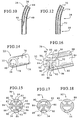
- Figure 5 is a perspective view of a portion the catheter of Fig. 1 showing fluid ports from a patient inflow lumen.
- Figure 6 is a cross-sectional view of the catheter of Fig. 1 along the line VI-VI..
- Figure 7 is a perspective view of a portion of the catheter of Fig. 1 showing an alternate fluid port from the patient inflow lumen.
- Figure 8 is a cross-sectional view along the line VI-VI of Fig. 1 showing the alternate embodiment of Fig. 7.
- Figure 9 is a cross-sectional view of the catheter of Fig. 1 along the line IX-IX.
- Figure 10 is a longitudinal cross-sectional view of a portion of the catheter of Fig. 1 which transitions from a patient inflow section to a separation section.
- Figure 11 is a cross-sectional view of the catheter of Fig. 1 along the line IX-IX showing an alternate cross-section.
- Figure 12 is a longitudinal cross-sectional view of a portion of the catheter of Fig. 1 which transitions from a patient inflow section to a separation section according to the alternate embodiment of Fig. 11.
- Figure 13 is a cross-sectional view of the catheter of Fig. 1 along the line XIII-XIII.
- Figure 14 is a perspective view of a portion the catheter of Fig. 1 according to Fig. 13.
- Figure 15 is a cross-sectional view along the line XIII-XIII of Fig. 1 showing an alternate fluid port to the patient outflow lumen.
- Figure 16 is a perspective view of a portion of the catheter of Fig. 1 showing the alternate embodiment of the fluid port to the patient inflow lumen of Fig. 15.
- Figure 17 is a cross-sectional view of the catheter of Fig. 1 along the line XIII-XIII showing an alternate cross-section.
- Figure 18 is a cross-sectional view of the catheter of Fig. 1 along the line XIII-XIII showing an alternate cross-section.
- Figure 19 is a cross-sectional view of the catheter of Fig. 1 along the line XIII-XIII showing an alternate cross-section.
- Figure 20 is a plan view of a portion of an alternate catheter according to the principles of the present invention.
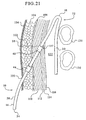
- Figure 21 is a schematic partial cross-sectional view of a patient showing the catheter of Fig. 1 implanted in the patient.
- Figure 22 is a schematic view showing the catheter of Fig. 1 being implanted into a patient.
- Although the present invention can be made in many different forms, the presently preferred embodiments are described in this disclosure and shown in the attached drawings. This disclosure exemplifies the principles of the present invention and does not limit the broad aspects of the invention only to the illustrated embodiments.
- A
new catheter 10 according to the principles of the present invention is shown by way of example in Fig. 1. Thecatheter 10 is implanted into a patient's peritoneal cavity for peritoneal dialysis. Referring also to Fig. 2, thecatheter 10 is shown partially in phantom implanted into apatient 12. Thecatheter 10 allows for dialysate to be infused into and removed out of the peritoneal cavity. Particularly, thecatheter 10 allows for continuous flow peritoneal dialysis treatment. Again, continuous flow peritoneal dialysis means that dialysate flows simultaneously into and out of the peritoneal cavity. Thecatheter 10 can also be used to perform other types of peritoneal dialysis. - The
catheter 10 is a dual lumen catheter which has two lumens or fluid flow paths through aflexible tube 14. One lumen provides for fluid to flow from outside the patient, through thecatheter 10, and into the patient, i.e. to infuse dialysate into the peritoneal cavity. The second lumen provides for fluid flow in the opposite direction. The second lumen allows fluid to flow from the peritoneal cavity, through thecatheter 10, and exit the patient. Continuous flow peritoneal dialysis can be performed on the patient because of the dual lumens in thecatheter 10. However, thecatheter 10 can be used without simultaneous fluid flow into and out of the patient. For example, the dialysis treatment may be controlled such that fluid flows through only one lumen at any given time. Also, only one lumen could be used, while the other lumen is not used, if desired. Although, thecatheter 10 is shown and described as asingle tube 14 having multiple lumens, other structures could be used. For example, thecatheter 10 could be made of two single lumen tubes joined together along their longitudinal lengths. - The
catheter 10 is made of flexiblemedical grade tubing 14 suitable for implanting inside a patient. Referring to Fig. 1, thecatheter 10 can be described as having four main sections, aconnection section 16, apatient inflow section 18, an inflow/outflow separation section 20, and apatient outflow section 22. Theconnection section 16 extends from an external catheter end 24 (proximal end) to ajunction 26 with thepatient inflow section 18. Thepatient inflow section 18 is a curved segment which extends from thejunction 26 to ajunction 28 with theseparation section 20. Theseparation section 20 extends from thejunction 28 with thepatient inflow section 18 to ajunction 30 with thepatient outflow section 22. Thepatient outflow section 22 extends from thejunction 30 to an internal catheter end 32 (distal end). The locations of thejunctions sections - Referring to Figs. 1 and 2, the
connection section 16 of thecatheter 10 provides the function of connecting thecatheter 10 to a dialysate supply and removal system, such as an automated continuous flow peritoneal dialysis system (not shown). Theexternal catheter end 24 is positioned external to thepatient 12 and is connected to the automated continuous flow peritoneal dialysis system. Thecatheter 10 has a generally vertical orientation when implanted into thepatient 12, with thepatient inflow section 18 positioned vertically upward, toward the upper area of the peritoneal cavity. Theconnection section 16 extends vertically downward and out of the patient 12 at anexit site 34. Theseparation section 20 also extends vertically downward from thepatient inflow section 18. Thepatient outflow section 22 is positioned downward toward the bottom of the peritoneal cavity. - An end view of the
external catheter end 24 is shown in Fig. 3. Apatient inflow lumen 36 allows fluid to flow into the patient from aport 38 at thecatheter end 24. Apatient outflow lumen 40 allows fluid to flow out of the patient from aport 42 at thecatheter end 24. Aseptum 44 separates the patient inflow andoutflow lumens outflow lumens dual lumen catheter 10. - Referring to Figs. 1 and 2, the
connection section 16 also provides for anchoring thecatheter 10 to the patient. One or more implant cuffs 46, 48 on theconnection section 16 anchor thecatheter 10 to the patient. The implant cuffs 46, 48 can be polyester felt or other material which allows tissue ingrowth into the cuffs. Thecatheter 10 is implanted into the patient with thecuff 46 positioned just below the patient's skin and thecuff 48 imbedded in the patient's rectus muscle. The subcutaneous tissue grows into the implant cuffs 46, 48 to anchor thecatheter 10 to the patient. When thecatheter 10 is implanted inside of a patient, the portion of thecatheter 10 from theexternal catheter end 24 close to thecuff 46 is external to the patient, and is called anexternal patient portion 50. The remainder of thecatheter 10 is implanted inside of the patient and is called animplantable portion 52. As shown in Fig. 1, theimplantable portion 52 has a generally non-linear shape, although portions of theimplantable portion 52 my be substantially linear. - A
radiopaque stripe 54 extends along the length of thecatheter 10 with reference to Figs. 1 and 3. Preferably, theradiopaque stripe 54 extends along thepatient outflow lumen 40; however, theradiopaque stripe 54 can be located at any position on thecatheter 10 as desired. Under x-ray, theradiopaque stripe 54 shows the position of thecatheter 10 inside of the patient. - Fig. 4 shows the
connection section 16 in cross-section along the section line IV-IV in Fig. 1. The cross-section of the connection section 16 (Fig. 4) is generally consistent along the length of theconnection section 16 from theexternal catheter end 24 to thejunction 26. Except, thecuffs junction 26 may change as theconnection section 16 transitions to thepatient inflow section 18, depending on the cross-section of thepatient inflow section 18. - Referring to Figs. 1 and 5, the
patient inflow section 18 has a fluid opening (port) 56 to thepatient inflow lumen 36 to allow dialysate to exit thepatient inflow lumen 36 and be infused into the peritoneal cavity. Thepatient inflow section 18 is preformed to a curved shape to form a curved segment. Preferably, thefluid opening 56 is a plurality of round holes through the catheter tube wall along the outer radial surface of thecurved inflow segment 18. The curved segment preferably spans an arc of about 180°; however, greater or lesser amounts of curvature can be used. When thecatheter 10 is implanted into a patient, thepatient inflow section 18 will be positioned generally towards to upper area of the peritoneal cavity, with the remainder of thecatheter 10 extending downward. - Fig. 6 shows the
patient inflow section 18 in cross-section along section line VI-VI of Fig. 1. The cross-section of thepatient inflow section 18 is consistent from theconnection section 16 to theseparation section 20, except for the transitions at thejunctions lumens fluid openings 56 in thepatient inflow section 18 for thepatient inflow lumen 36 are a plurality of round holes. Hole shape and sizes may be varied along the inflow section length in order to create a more uniform flow pattern or a specific flow velocity distribution if so desired. As shown in Fig. 5, there are two rows of evenly spaced holes 56. The two rows ofholes 56 are longitudinally offset from each other, however, the offset is not required for proper function of catheter. As shown in Fig. 6, the centerlines of theholes 56 in the two rows of holes form an angle of about 90°, however, other angles could be used. The location of theholes 56 allows for thorough mixing of dialysate within the peritoneal cavity. Referring to Fig. 1, the fluid holes 56 face in a direction away from thepatient outflow section 22. Accordingly, the dialysate entering into the peritoneal cavity from theholes 56 in thepatient inflow section 18 travels a tortuous path to reach thepatient outflow section 22. This tends to enhance dialysate contact on the peritoneal membrane and improve mxing. Improved dialysate contact with the peritoneal membrane and better mixing can improve the dialysis treatment of the patient. - The
patient inflow section 18 has been described as having a curved shape. The term curved contemplates structures other than a smooth curve of thetube 14, e.g. a non-linear shape. If one follows along thecatheter 10 from theproximal end 24 upward, thepatient inflow section 18 reverses the longitudinal direction of thecatheter 10 to a downward direction to reach thedistal end 32. In addition to having thefluid openings 56, thepatient inflow section 18 connectsconnection section 16 and theseparation section 20 together. Accordingly, the curved term contemplates many different shapes, such as an inverted U, an inverted V, a straighter line with right angles at the ends of the lines, and any other structure to connect theconnection section 16 to theseparation section 20. Also, thepatient inflow section 18 is preformed as a curved segment and generally retains its curved shape. Although thetube 14 is flexible, the form-retentive tube 14 will tend to retain its curved shape of thepatient inflow section 18 when implanted inside of the patient. Theentire tube 14 of thecatheter 10 has the flexible, form-retentive characteristic. - An alternative
patient inflow section 58 is shown in Figs. 7 and 8. Instead of the round holes for thefluid opening 56 in the patient inflow section 18 (Figs. 5 and 6), thepatient inflow section 58 has elongatedslots 60 to allow dialysate to flow into the peritoneal cavity. Also, the patient inflow lumen is twopatient inflow lumens 62 separated by aseptum 64. Theseptum 64 can have openings to allow fluid flow between bothpatient inflow lumens 62. Thefluid opening 56 can have shapes other than round holes and slots, as desired, for example, elongated holes. - Referring to Fig. 1, the
implantable portion 52 of thecatheter 10 has aseparation section 20. Theseparation section 20 is a generally straight section of theflexible tube 14 which separates thepatient inflow section 18 and thepatient outflow section 20 from each other. As described above, when thecatheter 10 is implanted into a patient, thepatient inflow section 18 is generally positioned at an upper area of the peritoneal cavity to deliver dialysate to the patient. Theseparation section 20 positionspatient outflow section 22 downward toward the lower area of the peritoneal cavity and away from thepatient inflow section 18. Theseparation section 20 allows dialysate flowing into the patient at thepatient inflow section 18 to travel a great distance in the peritoneal cavity to reach thepatient outflow section 22. The great distance of dialysate fluid flow in the peritoneal cavity also tends to improve the dialysis therapy because the dialysate can contact a greater portion (surface area) of the peritoneal membrane and improved mixing of fresh and spent dialysate can occur. - Fig. 9 shows a cross-section of the
separation section 20 from thejunction 28 with thepatient inflow section 18 to thejunction 30 with thepatient outflow section 22. In this embodiment, theseparation section 20 has thepatient outflow lumen 40 without thepatient inflow lumen 36 because thepatient inflow lumen 36 has been terminated. Fig. 10 shows a longitudinal cross-section of thecatheter 10 in the area of thejunction 28 between thepatient inflow section 18 and theseparation section 20. Thepatient inflow lumen 36 terminates at anend 66. Thecatheter 10 transitions from a dual lumen catheter to a single lumen catheter. - Figs. 11 and 12 show cross-sections of an
alternative separation section 68. In this embodiment,separation section 68 has both apatient inflow lumen 70 and apatient outflow lumen 72. Aseptum 74 separates the patient inflow andoutflow lumens patient inflow lumen 70 may terminate and be closed at or before thedistal catheter end 32. - The
patient outflow section 22 is shown in Fig. 1. Thepatient outflow section 22 has a preformed, coiled shape. A fluid opening (port) 76 and the opendistal end 32 are open to thepatient outflow lumen 40 to allow fluid to exit the peritoneal cavity through thecatheter 10. Referring also to Figs. 13 and 14, the fluid opening is preferably a plurality ofholes 76 generally all around the exterior of thetube 14 from thejunction 30 to thedistal end 32. Thepatient outflow section 22 with thefluid opening 76 is spaced a great distance from thepatient inflow section 18 and thefluid opening 56. Accordingly, dialysate fluid must flow from the patient inflow section 18 - positioned in the upper area of the peritoneal cavity - a great distance to the patient outflow section 22 - positioned in the lower area of the peritoneal cavity. The inflow and outflow of dialysate fluid through thecatheter 10 can occur simultaneously. - Figs. 15 and 16 show an alternative
patient outflow section 78. In this embodiment, instead ofholes 76, the fluid opening is a plurality ofelongated slots 80.Several septums 82 are connected together and hold theouter tube portions 84 together. The patient outflow lumen is partitioned into severalpatient outflow lumens 86 by theseptums 82. Theseptums 82 can have openings to allow fluid flow between any of thepatient outflow lumens 86. Of course, thefluid opening 76 in the patient outflow section could have shapes other than holes and slots as desired. - Figs. 17-19 show additional alternate cross-sections of the
patient outflow section 22. In Fig. 17, thepatient outflow section 88 hasslots 80 on only the side of the tube having theradiopaque stripe 54.Lumen 90 can be part of the patient outflow lumen by carrying fluid out of the patient from an opendistal end 32 and/or from fluid openings through theseptums 82 to thelumens 86. Thelumen 90 could be part of thepatient inflow lumen 36, but would have a closed end at or prior to thedistal end 32. Thepatient outflow section 88 of Fig. 17 may have greater structural strength aroundlumen 90 because there are no slots opposite theradiopaque stripe 54. Accordingly, thelumen 90 may provide greater containment of a stiffening stylet inserted into thelumen 90 during implantation of thecatheter 10. The patient outflow section 92 of Fig. 18 is similar to thepatient outflow section 88 of Fig. 17. Except, theslots 80 in the Fig. 18 embodiment are on the side of the tube opposite the radiopaque stripe. Thepatient outflow section 94 of Fig. 19 is similar to thepatient outflow section 88 of Fig. 17. Except, holes 76 replace theslots 80. - Fig. 20 shows an alternative embodiment of the
catheter 10. In this embodiment, thecatheter 10 is generally the same as previously described embodiments, except for thepatient outflow section 22. The flexiblepatient outflow section 96 has a substantially straight shape rather than the coiled shape of thepatient outflow section 22 shown in Fig. 1. Thepatient outflow section 96 has a port, such as a plurality ofholes 76 orslots 80, for thepatient outflow lumen 40. The cross-sections of the patient outflow sections shown in Figs. 13, 15, and 17-19 are also applicable to thepatient outflow section 96 of Fig. 20. - Implantation of the
catheter 10 into a patient will now be described. Generally, thecatheter 10 can be implanted by accepted catheter implantation methods, including open surgical dissection, peritoneoscopic, and percutaneous, for example, with modifications due to the new catheters of the present invention. Because the open surgical dissection method is the most commonly used implantation method for existing peritoneal dialysis catheters, an open surgical dissection implantation method for thecatheter 10 will be described. This disclosure of the invention is not a medical text and, thus, the procedural steps described below do not constitute a complete formal medical procedure. Medical professionals should determine and apply all appropriate procedures. - Preparation for catheter placement should follow accepted hospital procedures for general abdominal surgery.
- 1. Empty the patient's bowel and bladder. An enema should be used, if necessary.
- 2. Shave the insertion area and mark entrance and exit locations with a sterile ink pen. Referring to Fig. 21, the
entrance site 98 will be located approximately 3 - 6 cm directly above theexit site 100, or above and slightly to the side of theexit site 100. These locations of the entrance andexit sites external patient portion 50 of thecatheter 10 to be directed downward and theimplantable portion 52 to point upward to thepatient inflow section 18. - 3. Prepare the sterile field. After a Betadine scrub, the entrance and exit markings may need to be reapplied.
- 4. Anesthetize the area locally where the initial incision, tunnel and subsequent skin puncture will be made. Avoid general anesthesia whenever possible.
- 5. Patient is now ready for implantation of the
catheter 10. -
- 1. A 3 - 4 cm
transverse incision 102 is made through theskin 104 andsubcutaneous tissue 106. Thetransverse incision 102 is continued down through theanterior rectus sheath 108. - 2. The
rectus muscle fibers 110 are separated to expose theposterior rectus sheath 112. - 3. An incision is made through the
posterior rectus sheath 112,transversalis fascia 114, andparietal peritoneum 116 no larger than necessary to introduce thecatheter 10. - 4. A purse-
string suture 117 is placed around the incision to help seal after catheter insertion. - 5. The
catheter 10 is placed in a sterile saline bath while compressing thecuffs - 6. Referring to Figs. 21 and 22, a stiffening
stylet 118 is inserted into the patient outflow lumen 40 (lumen identified by radiopaque stripe) of thecatheter 10. Thestylet 118 stiffens thecatheter 10 and straightens the curvedpatient inflow section 18 and the coiledpatient outflow section 22 for easier insertion. Thestylet 118 should fall at least 1 cm short of thedistal end 32 of thecatheter 10 to prevent perforation of thebowel 120 or other intraperitoneal injury. - 7. As shown in Fig. 22, the
catheter 10 is initially directed downward toward the lower pelvis with thestylet 118 pointing downward. With the coiledpatient outflow section 22 embodiment, once the catheter tip (distal end 32) is deep in the pelvic cavity thestylet 118 is slowly removed approximately 20 cm while simultaneously advancing thecatheter 10 deeper to allow the coil to reform its coiled shape and remain low in the pelvis. - 8. Once the catheter tip (distal end 32), coiled or straight embodiments, is properly located low in the pelvis, the
stylet 118 removed another 10 cm while advancing thecatheter 10 inward by the same amount. At this point thestylet 118 should remain fixed while advancing thecatheter 10 all the way into theperitoneum 122 until thedistal cuff 48 is seated firmly in therectus muscle 110 but not protruding into theperitoneum 122. - 9. The portion of the
stylet 118 andcatheter 10 external to the patient is rotated approximately 135° downward with the portion of thestylet 118 andcatheter 10 inside of the patient rotated upward as shown in Fig. 22 to force thepatient inflow section 18 into the upper portion of the abdomen near the liver. During this step thecatheter 10 should be kept as close to the abdominal wall as possible. Ideal placement would result in thecatheter 10 lying in the area between the intestinal mass (bowels 120) and the posterior abdominal wall as shown in Fig. 21. - 10. The purse-
string suture 117 is firmly cinched around thecatheter 10. An additional suture can be added to secure thecuff 48 to therectus muscle 110 if desired. -
- 1. A tunneling tool is inserted into one of the
catheter lumens - 2. A small scalpel puncture is made at the
premarked exit site 100 location which is directly below or below and slightly to one side of theentrance site 98 location. - 3. Referring to Fig. 21, the tunneling tool with
catheter 10 attached is advanced from the originalentrance site incision 102, under theskin 104 and out the scalpel puncture at theexit site 100 forming a straight, stress-free subcutaneous tunneL Thecatheter 10 is pulled through the tunnel until thecatheter 10 is straightened and theproximal cuff 46 is approximately 2 cm below the skin surface. -
- 1. An adapter is attached to the
proximal end 24 of thecatheter 10 and catheter flow is assessed by infusing and draining saline solution through bothlumens - 2. Once the fluid flow function is validated, the
entrance site incision 102 is closed. Suturing ofexit site 100 is not recommended. - 3. The
catheter 10 is secured to the skin and the exit wound is dressed appropriately. - Dialysis may begin as early as required, but recommended no sooner than 2 weeks.
- The
catheter 10 and the implantation method provides for an unstressed, straight tunnel through the patient's tissue into theperitoneal cavity 122. Also, theexit site 100 is directed downward so theexternal patient portion 50 of thecatheter 10 is positioned in a downward direction. Thecatheter 10 can have a close implant cuff spacing (small distance between implant cuffs 46, 48). Accordingly, only a small length of catheter tubing between the implant cuffs 46, 48 will be positioned within the patient's abdominal wall tissue. - While the presently preferred embodiments have been illustrated and described, numerous changes and modifications can be made without significantly departing from the spirit and scope of this invention. Therefore, the inventors intend that such changes and modifications are covered by the appended claims.
Claims (37)
- A dialysis catheter comprising:a tube having an implantable portion extending from an external patient portion, the implantable portion having a curved segment between the external patient portion and a distal end of the implantable portion;a first lumen extending through the tube from a first lumen port in the external patient portion to a first lumen port in the curved segment of the implantable portion; anda second lumen extending through the tube from a second lumen port in the external patient portion to a second lumen port in the implantable portion, the second lumen port in the implantable portion being spaced away from the first lumen port in the curved segment.
- The dialysis catheter of claim 1, further comprising at least one implant cuff on the implantable portion of the tube.
- The dialysis catheter of claim 1, wherein the first lumen port in the curved segment comprises a plurality of openings at an outer radial surface of the curved segment.
- The dialysis catheter of claim 3, wherein the plurality of openings are substantially round holes.
- The dialysis catheter of claim 3, wherein the plurality of openings are slots.
- The dialysis catheter of claim 1, wherein the implantable portion has a coiled shape at the distal end.
- The dialysis catheter of claim 6, wherein the second lumen port in the implantable portion comprises a plurality of holes.
- The dialysis catheter of claim 6, wherein the second lumen port in the implantable portion comprises a plurality of slots.
- The dialysis catheter of claim 1, wherein the implantable portion has a substantially straight shape at the distal end.
- The dialysis catheter of claim 9, wherein the second lumen port in the implantable portion comprises a plurality of holes.
- The dialysis catheter of claim 9, wherein the second lumen port in the implantable portion comprises a plurality of slots.
- The dialysis catheter of claim 1, wherein the tube is a single tube having a septum between the first and second lumens.
- The dialysis catheter of claim 1, wherein the first lumen port in the curved segment is a patient inflow port.
- The dialysis catheter of claim 1, wherein the second lumen port in the implantable portion is a patient outflow port.
- The dialysis catheter of claim 1, wherein the first lumen terminates prior to the distal end of the implantable portion.
- A dialysis catheter comprising:a connection section having an inflow port to a patient inflow lumen, and an outflow port to a patient outflow lumen;a patient inflow section extending from the connection section and having a patient inflow opening to the patient inflow lumen;a separation section extending from the patient inflow section; anda patient outflow section extending from the separation section and having a patient outflow opening to the patient outflow lumen.
- The dialysis catheter of claim 16, wherein when the catheter is in a substantially unstressed condition, the connection section is substantially straight, the patient inflow section is curved, and the separation section is substantially straight.
- The dialysis catheter of claim 17, wherein the patient outflow section is coiled.
- The dialysis catheter of claim 17 wherein the patient outflow section is substantially straight.
- The dialysis catheter of claim 16, wherein the patient inflow section is an uppermost portion of an implantable portion of the catheter and the patient outflow section is a lowermost portion of the implantable portion of the catheter.
- The dialysis catheter of claim 16, wherein the connection section, patient inflow section, separation section, and patient outflow section further comprise a flexible tube having an internal septum between the patient inflow and outflow lumens.
- The dialysis catheter of claim 16, wherein the patient inflow section has a curved shape.
- The dialysis catheter of claim 16, wherein the patient inflow opening to the patient inflow lumen is in a direction away from the patient outflow opening to the patient outflow lumen.
- The dialysis catheter of claim 16, wherein the catheter comprises a single tube having the patient inflow and outflow lumens, and wherein the tube transitions from having both the patient inflow and outflow lumens to having only the patient outflow lumen at a location between the patient inflow section and a distal catheter end.
- A peritoneal dialysis catheter comprising a flexible single tube having first and second lumens, the first lumen extending from a first fluid opening to a second fluid opening, the second lumen extending from a third fluid opening to a fourth fluid opening, the first and third fluid openings being in an external patient portion of the catheter, the second and fourth fluid openings being in an implantable portion of the catheter and spaced apart from each other, the implantable portion of the catheter have an generally non-linear shape.
- The peritoneal dialysis catheter of claim 25, wherein the second fluid opening is located at anon-linear shaped section of the implantable portion
- The peritoneal dialysis catheter of claim 25, wherein the second and fourth fluid openings are separated by a substantially linear tube section which is absent fluid openings to an exterior of the catheter.
- The peritoneal dialysis catheter of claim 25, wherein the second fluid opening is located at a vertically uppermost portion of the implantable portion and the fourth fluid opening is located at a vertically lowermost portion of the implantable portion.
- A dialysis catheter comprising:a substantially straight connection section;a non-linear patient inflow section extending from the connection section;a separation section extending from the patient inflow section;a patient outflow section extending from the separation section;a patient inflow lurnen extending from the connection section to the patient inflow section; anda patient outflow lumen extending from the connection section to the patient outflow section.
- The dialysis catheter of claim 29, wherein the separation section has a substantially straight shape.
- The dialysis catheter of claim 29, wherein the patient outflow section has a coiled shape.
- The dialysis catheter of claim 29, wherein the patient inflow section has a curved shape of about 180°.
- A peritoneal dialysis catheter having first and second lumens, comprising:a dialysis machine connection section having fluid ports to the first and second lumens;a non-linear section extending from the connection section and having a fluid port to the first lumen;a separation section extending from the non-linear section; anda distal end section extending from the separation section and having a fluid port to the second lumen.
- The peritoneal dialysis catheter of claim 33, wherein the first lumen is a patient inflow lumen and the second lumen is a patient outflow lumen.
- The peritoneal dialysis catheter of claim 33, wherein the non-linear section has a curved shape and the fluid port in the non-linear section is pointed in a direction opposite the fluid port in the distal end section.
- A method of flowing fluid through a catheter comprising the steps offlowing fluid into a first lumen at a proximal end of the catheter;flowing the fluid in the first lumen to a curved path of the first lumen;flowing the fluid in the curved path through a fluid opening in the curved path and out of the catheter;flowing the fluid which exited the catheter from the opening in the curved path into a second lumen at a distal end of the catheter; andflowing the fluid in the second lumen to a fluid opening at the proximal end of the catheter and out of the catheter.
- A method of implanting a catheter into a patient comprising the steps ofstraightening the catheter with a stylet inside of the catheter;inserting a distal end of the straightened catheter through an entrance incision into a peritoneal cavity of the patient while directing the straightened catheter downward;removing part of the stylet from the catheter while advancing the catheter into the peritoneal cavity until the distal end is located in a lower area of the peritoneal cavity and a distal implant cuff is seated in a rectus muscle of the patient;rotating a portion of the stylet and catheter outside of the patient downward and a portion of the stylet and catheter inside of the patient upward; andpulling the catheter through a subcutaneous tunnel having an exit site below the entrance incision.
Applications Claiming Priority (2)
| Application Number | Priority Date | Filing Date | Title |
|---|---|---|---|
| US09/689,508 US6976973B1 (en) | 2000-10-12 | 2000-10-12 | Peritoneal dialysis catheters |
| EP01979903A EP1324787B1 (en) | 2000-10-12 | 2001-09-28 | Peritoneal dialysis catheters |
Related Parent Applications (2)
| Application Number | Title | Priority Date | Filing Date |
|---|---|---|---|
| EP01979903.0 Division | 2001-09-28 | ||
| EP01979903A Division EP1324787B1 (en) | 2000-10-12 | 2001-09-28 | Peritoneal dialysis catheters |
Publications (2)
| Publication Number | Publication Date |
|---|---|
| EP1772161A1 true EP1772161A1 (en) | 2007-04-11 |
| EP1772161B1 EP1772161B1 (en) | 2010-04-07 |
Family
ID=24768762
Family Applications (2)
| Application Number | Title | Priority Date | Filing Date |
|---|---|---|---|
| EP01979903A Expired - Lifetime EP1324787B1 (en) | 2000-10-12 | 2001-09-28 | Peritoneal dialysis catheters |
| EP06077310A Expired - Lifetime EP1772161B1 (en) | 2000-10-12 | 2001-09-28 | Peritoneal dialysis catheters |
Family Applications Before (1)
| Application Number | Title | Priority Date | Filing Date |
|---|---|---|---|
| EP01979903A Expired - Lifetime EP1324787B1 (en) | 2000-10-12 | 2001-09-28 | Peritoneal dialysis catheters |
Country Status (14)
| Country | Link |
|---|---|
| US (2) | US6976973B1 (en) |
| EP (2) | EP1324787B1 (en) |
| JP (2) | JP4335523B2 (en) |
| KR (1) | KR20030040534A (en) |
| CN (1) | CN1494442A (en) |
| AR (1) | AR031617A1 (en) |
| AT (2) | ATE463268T1 (en) |
| AU (1) | AU2002211820A1 (en) |
| BR (1) | BR0114599A (en) |
| CA (1) | CA2425501C (en) |
| DE (2) | DE60141780D1 (en) |
| MX (1) | MXPA03003239A (en) |
| TW (1) | TW510804B (en) |
| WO (1) | WO2002030489A2 (en) |
Cited By (1)
| Publication number | Priority date | Publication date | Assignee | Title |
|---|---|---|---|---|
| WO2010059964A1 (en) * | 2008-11-21 | 2010-05-27 | Baxter International Inc. | Systems and methods for removing air from the patient's peritoneal cavity |
Families Citing this family (89)
| Publication number | Priority date | Publication date | Assignee | Title |
|---|---|---|---|---|
| US6749580B2 (en) * | 2001-10-05 | 2004-06-15 | Medical Components, Inc. | Catheter |
| US7241272B2 (en) | 2001-11-13 | 2007-07-10 | Baxter International Inc. | Method and composition for removing uremic toxins in dialysis processes |
| EP2298377A1 (en) * | 2002-07-19 | 2011-03-23 | Baxter International Inc. | Systems and methods for peritoneal dialysis |
| JP4890761B2 (en) * | 2002-07-19 | 2012-03-07 | バクスター・インターナショナル・インコーポレイテッド | System and method for performing peritoneal dialysis |
| US20040034333A1 (en) | 2002-08-19 | 2004-02-19 | Seese Timothy M. | Dialysis catheters with optimized user-friendly connections |
| US7163531B2 (en) | 2002-08-19 | 2007-01-16 | Baxter International, Inc. | User-friendly catheter connection adapters for optimized connection to multiple lumen catheters |
| US20040087886A1 (en) | 2002-10-30 | 2004-05-06 | Scimed Life Systems, Inc. | Linearly expandable ureteral stent |
| US7141035B2 (en) * | 2003-03-28 | 2006-11-28 | Sherwood Services Ag | Catheter with occlusion resistant tip |
| WO2005025645A2 (en) * | 2003-09-08 | 2005-03-24 | Ash Access Technology, Inc. | Anti-clotting indwelling catheter |
| AU2004293815B2 (en) * | 2003-11-20 | 2010-07-22 | The Henry M. Jackson Foundation For The Advancement Of Military Medicine, Inc. | Portable hand pump for evacuation of fluids |
| US8202248B2 (en) | 2004-08-18 | 2012-06-19 | Sequana Medical Ag | Dialysis implant and methods of use |
| US8337475B2 (en) | 2004-10-12 | 2012-12-25 | C. R. Bard, Inc. | Corporeal drainage system |
| CA2586398A1 (en) * | 2004-12-21 | 2006-06-29 | C.R. Bard, Inc. | Hemostasis cuff for catheter securement |
| US9126011B2 (en) * | 2006-03-24 | 2015-09-08 | Merit Medical Systems, Inc. | Anti-clotting indwelling catheter |
| US8177772B2 (en) | 2005-09-26 | 2012-05-15 | C. R. Bard, Inc. | Catheter connection systems |
| ES2476999T3 (en) | 2005-10-11 | 2014-07-15 | Impedimed Limited | Hydration Status Monitoring |
| US8029457B2 (en) | 2006-03-24 | 2011-10-04 | Aat Catheter Technologies, Llc | Indwelling catheter with anti-clotting features |
| WO2007120505A1 (en) * | 2006-03-31 | 2007-10-25 | C. R. Bard, Inc. | Catheter including arcuate transition region |
| USD558341S1 (en) * | 2006-09-19 | 2007-12-25 | Tyco Healthcare Group Lp | Two slot cruciform catheter section |
| US20080082079A1 (en) | 2006-09-28 | 2008-04-03 | Tyco Healthcare Group Lp | Low profile catheter assembly |
| US9168355B2 (en) | 2006-09-29 | 2015-10-27 | Covidien Lp | Acute hemodialysis catheter assembly |
| USD558342S1 (en) * | 2007-03-19 | 2007-12-25 | Tyco Healthcare Group Lp | Three slot cruciform catheter section |
| US20090005762A1 (en) * | 2007-06-26 | 2009-01-01 | Vasu Nishtala | Bioabsorbable Drain Tube |
| US20090018493A1 (en) * | 2007-07-10 | 2009-01-15 | Ash Stephen R | Implantable catheter assembly |
| US20090054874A1 (en) * | 2007-08-23 | 2009-02-26 | C. R. Bard, Inc. | Multi-lumen catheter including a lumen having a variable cross sectional area |
| JP5184308B2 (en) * | 2007-12-04 | 2013-04-17 | 株式会社荏原製作所 | Plating apparatus and plating method |
| DK2268200T3 (en) | 2008-03-18 | 2019-01-07 | Circa Scient Llc | TEMPERATURE MEASURING EQUIPMENT WITH LARGE SURFACE AREA |
| US9833149B2 (en) * | 2008-03-18 | 2017-12-05 | Circa Scientific, Llc | Methods, apparatus and systems for facilitating introduction of shaped medical instruments into the body of a subject |
| WO2009123729A1 (en) * | 2008-04-02 | 2009-10-08 | The Trustees Of The University Of Pennsylvania | Dual lumen dialysis catheter with internally bored or externally-grooved small bore |
| JP2009273609A (en) | 2008-05-14 | 2009-11-26 | Nippon Sherwood Medical Industries Ltd | Catheter with valve |
| US9005154B2 (en) | 2008-09-26 | 2015-04-14 | Covidien Lp | Valved hemodialysis catheter |
| US20100298839A1 (en) * | 2009-01-15 | 2010-11-25 | Salvatore Castro | Peelable Sheath and Method of Use |
| US11278653B2 (en) | 2009-01-29 | 2022-03-22 | Baxter International Inc. | Method and apparatus for trending automated peritoneal dialysis treatments |
| US8142649B2 (en) | 2009-01-29 | 2012-03-27 | Baxter International Inc. | Method for optimizing tidal therapies employing ultrafiltrate trending |
| US8182673B2 (en) | 2009-01-29 | 2012-05-22 | Baxter International Inc. | Drain and fill logic for automated peritoneal dialysis |
| US8521482B2 (en) * | 2009-02-20 | 2013-08-27 | Baxter International Inc. | Simulation of patient drain phase in peritoneal dialysis |
| JP2011050420A (en) | 2009-08-31 | 2011-03-17 | Nippon Sherwood Medical Industries Ltd | Valved catheter |
| CA2715857A1 (en) | 2009-09-30 | 2011-03-30 | Tyco Healthcare Group Lp | Medical catheter having a design providing low recirculation and reversibility |
| US9622670B2 (en) | 2010-07-09 | 2017-04-18 | Potrero Medical, Inc. | Method and apparatus for pressure measurement |
| US8936720B2 (en) | 2010-09-17 | 2015-01-20 | Baxter International Inc. | Drain and fill logic for automated peritoneal dialysis |
| WO2012080783A1 (en) * | 2010-12-15 | 2012-06-21 | Querol Garcia Valeria | Three-lobe drainage hose |
| US9039652B2 (en) | 2011-02-16 | 2015-05-26 | Sequana Medical Ag | Apparatus and methods for treating intracorporeal fluid accumulation |
| JP5713732B2 (en) | 2011-03-08 | 2015-05-07 | 日本コヴィディエン株式会社 | Catheter with valve |
| US20130172807A1 (en) * | 2011-05-26 | 2013-07-04 | Cosme Cruz | Peritoneal Dialysis Catheter |
| EP2741806B1 (en) | 2011-08-11 | 2018-11-07 | Medical Components, Inc. | Apparatus for the dialysis of blood |
| US9072867B2 (en) | 2011-09-30 | 2015-07-07 | Covidien Lp | Catheter with external flow channel |
| US8747343B2 (en) | 2011-09-30 | 2014-06-10 | Covidien Lp | Hemodialysis catheter with improved side opening design |
| US8585635B2 (en) | 2012-02-15 | 2013-11-19 | Sequana Medical Ag | Systems and methods for treating chronic liver failure based on peritoneal dialysis |
| US10143822B2 (en) | 2012-07-05 | 2018-12-04 | Covidien Lp | Valved tip catheters |
| US9254203B2 (en) | 2012-08-20 | 2016-02-09 | Boston Scientific Scimed, Inc. | Delivery device |
| US9155862B2 (en) | 2012-09-28 | 2015-10-13 | Covidien Lp | Symmetrical tip acute catheter |
| USD743542S1 (en) | 2012-10-31 | 2015-11-17 | Sequana Medical Ag | Catheter with staggered slits |
| US9144660B2 (en) | 2012-10-31 | 2015-09-29 | Sequana Medical Ag | Implantable catheters with staggered slits, and methods of using same |
| USD743543S1 (en) | 2012-10-31 | 2015-11-17 | Sequana Medical Ag | Catheter with staggered slits |
| ES2817789T3 (en) | 2012-11-12 | 2021-04-08 | Hollister Inc | Intermittent catheter assembly |
| EP2919825B1 (en) | 2012-11-14 | 2018-10-17 | Hollister Incorporated | Disposable catheter with selectively degradable inner core |
| US10252023B2 (en) | 2013-01-11 | 2019-04-09 | C. R. Bard, Inc. | Curved catheter and methods for making same |
| JP6186818B2 (en) * | 2013-04-05 | 2017-08-30 | ニプロ株式会社 | Drain catheter |
| DK3862031T3 (en) | 2013-11-08 | 2023-09-25 | Hollister Inc | LUBRICATED, OLEOFILIC CATHETERS |
| LT3079749T (en) | 2013-12-12 | 2019-12-27 | Hollister Incorporated | Flushable catheters |
| HUE049637T2 (en) | 2013-12-12 | 2020-09-28 | Hollister Inc | Removable catheters in the toilet |
| AU2014363933B2 (en) | 2013-12-12 | 2019-10-10 | Hollister Incorporated | Flushable disintegration catheter |
| LT3079750T (en) | 2013-12-12 | 2020-07-27 | Hollister Incorporated | Flushable catheters |
| US10350387B2 (en) * | 2014-06-02 | 2019-07-16 | Medtronic, Inc. | Implant tool for substernal or pericardial access |
| CN104383620A (en) * | 2014-11-20 | 2015-03-04 | 上海交通大学医学院附属新华医院 | Novel dual-channel peritoneal dialysis catheter suitable for operation under endoscope |
| LT3310404T (en) | 2015-06-17 | 2024-04-10 | Hollister Incorporated | Selectively water disintegrable materials and catheters made of such materials |
| US20170095641A1 (en) * | 2015-10-06 | 2017-04-06 | Covidien Lp | Catheter with curvilinear polygon cross-sectional shape |
| US9861734B2 (en) * | 2016-03-21 | 2018-01-09 | King Saud University | Bifurcated peritoneal catheter |
| AU2017299466B2 (en) | 2016-07-18 | 2022-07-14 | Merit Medical Systems, Inc. | Inflatable radial artery compression device |
| JP7071338B2 (en) | 2016-08-26 | 2022-05-18 | セクアナ メディカル エヌブイ | Systems and methods for managing and analyzing data generated by embedded devices |
| US10716922B2 (en) | 2016-08-26 | 2020-07-21 | Sequana Medical Nv | Implantable fluid management system having clog resistant catheters, and methods of using same |
| CN107041979A (en) * | 2016-12-13 | 2017-08-15 | 上海市杨浦区中心医院 | Nephrology dept.'s peritoneum dialysis catheter |
| CN108245225A (en) * | 2016-12-29 | 2018-07-06 | 上海长海医院 | A kind of Multi-channel liquid, solid, gas intervention hose |
| US10918778B2 (en) | 2017-05-24 | 2021-02-16 | Sequana Medical Nv | Direct sodium removal method, solution and apparatus to reduce fluid overload in heart failure patients |
| US11559618B2 (en) | 2017-05-24 | 2023-01-24 | Sequana Medical Nv | Formulations and methods for direct sodium removal in patients having severe renal dysfunction |
| DE102018000834A1 (en) * | 2018-02-01 | 2019-08-01 | Paragon Ag | Microphone arrangement for the interior of a motor vehicle |
| USD905853S1 (en) | 2018-02-27 | 2020-12-22 | Medical Components, Inc. | Catheter tip |
| WO2020146454A1 (en) * | 2019-01-08 | 2020-07-16 | The Regents Of The University Of California | Advanced drainage catheter |
| CA3148818C (en) * | 2019-07-31 | 2024-06-11 | Jose Ramirez | Accessing assembly for hemodialysis administration |
| CN110665081A (en) * | 2019-11-04 | 2020-01-10 | 昆明医科大学第一附属医院 | Sealed peritoneal dialysis device |
| US12484911B2 (en) | 2020-08-13 | 2025-12-02 | Merit Medical Systems, Inc. | Inflatable radial artery compression device with cinching wristband and method of use |
| CN112023163B (en) * | 2020-09-14 | 2023-08-01 | 中国人民解放军联勤保障部队第九〇〇医院 | Peritoneal dialysis tube for nephrology department |
| USD984880S1 (en) | 2020-11-06 | 2023-05-02 | Medical Components, Inc. | Clamp with indicator |
| CN114533994A (en) * | 2020-11-25 | 2022-05-27 | 百特国际有限公司 | Medical fluid container assembly system and method |
| WO2022125870A1 (en) * | 2020-12-11 | 2022-06-16 | Mcglynn Patrick | Ureteral access peritoneal catheter |
| CA3205951A1 (en) * | 2020-12-29 | 2022-07-07 | Baxter International Inc. | Peritoneal dialysis system using disinfection |
| WO2022225820A1 (en) | 2021-04-19 | 2022-10-27 | Baxter International Inc. | Peritoneal dialysis system using ideal gas law |
| US12426864B2 (en) | 2021-06-18 | 2025-09-30 | Merit Medical Systems, Inc. | Hemostasis devices and methods of use |
| US12496385B2 (en) | 2021-07-19 | 2025-12-16 | Graham Braswell Biotechnologies Inc. | Peritoneal dialysis catheter with an expandable structure |
Citations (6)
| Publication number | Priority date | Publication date | Assignee | Title |
|---|---|---|---|---|
| US4772269A (en) * | 1985-05-01 | 1988-09-20 | Curators Of The University Of Missouri | Peritoneal dialysis catheter |
| EP0509715A1 (en) * | 1991-04-16 | 1992-10-21 | The Curators Of The University Of Missouri | Peritoneal dialysis catheter |
| US5509897A (en) * | 1990-01-08 | 1996-04-23 | The Curators Of The University Of Missouri | Multiple lumen catheter for hemodialysis |
| WO1997037699A1 (en) * | 1996-04-11 | 1997-10-16 | Sherwood Medical Company | Triple lumen catheter |
| US5961486A (en) * | 1995-02-09 | 1999-10-05 | Twardowski; Zbylut J. | Clot resistant multiple lumen catheter |
| US5989213A (en) * | 1998-01-06 | 1999-11-23 | Maginot Vascular Systems | Long-term dialysis catheter system and associated method |
Family Cites Families (93)
| Publication number | Priority date | Publication date | Assignee | Title |
|---|---|---|---|---|
| US3707967A (en) | 1970-10-01 | 1973-01-02 | Tecna Corp | Steady flow regenerative peritoneal dialysis system and method |
| US4351333A (en) | 1975-10-28 | 1982-09-28 | Harrison Lazarus | Peritoneal fluid treatment apparatus, package and method |
| US4239041A (en) | 1977-03-03 | 1980-12-16 | Moncrief Jack W | Method for continuous ambulatory peritoneal dialysis |
| US4184497A (en) | 1977-08-26 | 1980-01-22 | University Of Utah | Peritoneal dialysis catheter |
| IT1166846B (en) | 1979-05-25 | 1987-05-06 | Bieffe Spa | METHOD AND DEVICE FOR AMBULANT PERITONEAL DIALIS |
| IT7943514A0 (en) | 1979-10-26 | 1979-10-26 | Buoncristiani Vincenzo | AUTOMATIC EQUIPMENT FOR PERITONEAL DIALYSIS WITH RECYCLING OF THE DISCHARGE LIQUID DURING THE DIALYTIC SESSION |
| US4368737A (en) | 1980-07-07 | 1983-01-18 | Purdue Research Foundation | Implantable catheter |
| US4398910A (en) | 1981-02-26 | 1983-08-16 | Blake L W | Wound drain catheter |
| US4465481A (en) | 1981-02-26 | 1984-08-14 | Innovative Surgical Products, Inc. | Single piece wound drain catheter |
| US4496349A (en) | 1981-05-08 | 1985-01-29 | Renal Systems, Inc. | Percutaneous implant |
| USD272651S (en) | 1981-11-02 | 1984-02-14 | Mahurkar Sakharam D | Double lumen catheter |
| US4396382A (en) | 1981-12-07 | 1983-08-02 | Travenol European Research And Development Centre | Multiple chamber system for peritoneal dialysis |
| US4490137A (en) | 1982-09-30 | 1984-12-25 | Moukheibir Nabil W | Surgically implantable peritoneal dialysis apparatus |
| US4498902A (en) | 1982-11-13 | 1985-02-12 | Purdue Research Foundation | Catheter guide |
| US4543087A (en) * | 1983-11-14 | 1985-09-24 | Quinton Instrument Company | Double lumen catheter tip |
| US5197951A (en) | 1983-12-14 | 1993-03-30 | Mahurkar Sakharam D | Simple double lumen catheter |
| US4586920A (en) | 1984-07-09 | 1986-05-06 | Peabody Alan M | Continuous flow peritoneal dialysis system and method |
| US4581012A (en) | 1984-12-05 | 1986-04-08 | I-Flow Corporation | Multilumen catheter set |
| US4687471A (en) | 1985-05-01 | 1987-08-18 | Curators Of The University Of Missouri | Peritoneal dialysis catheter |
| DE3522782A1 (en) | 1985-06-26 | 1987-01-15 | Peter Brehm Chir Mechanik Werk | Double-lumen follicle-biopsy cannula |
| US5527274A (en) * | 1986-06-09 | 1996-06-18 | Development Collaborative Corporation | Catheter for chemical contact dissolution of gallstones |
| US4832054A (en) | 1986-07-07 | 1989-05-23 | Medical Engineering Corporation | Septum |
| SE455368B (en) | 1986-11-11 | 1988-07-11 | Roger Hellgren | DEVICES FOR INTESTINAL ASPIRATION / PERFUSION |
| DE3739556A1 (en) | 1987-11-21 | 1989-06-01 | Braun Melsungen Ag | CATHETER |
| CA1330285C (en) | 1987-12-22 | 1994-06-21 | Geoffrey S. Martin | Triple lumen catheter |
| EP0333308B1 (en) | 1988-03-17 | 1995-01-11 | Vas-Cath Incorporated | Dual lumen catheter |
| US5057073A (en) | 1988-04-21 | 1991-10-15 | Vas-Cath Incorporated | Dual lumen catheter |
| US5188593A (en) * | 1988-04-21 | 1993-02-23 | Vas-Cath Incorporated | Dual lumen catheter |
| US4895561A (en) | 1988-05-16 | 1990-01-23 | Mahurkar Sakharam D | Dual-lumen catheter-connecting system |
| GB8824855D0 (en) | 1988-10-24 | 1988-11-30 | Byrne P O | Dialysis |
| US5053023A (en) | 1988-10-25 | 1991-10-01 | Vas-Cath Incorporated | Catheter for prolonged access |
| DE3903119C1 (en) | 1989-02-02 | 1990-08-09 | Willy Ruesch Ag, 7053 Kernen, De | |
| US5098413A (en) | 1989-03-13 | 1992-03-24 | Sil-Med Corporation | Peritoneal catheter |
| US5057075A (en) * | 1989-12-13 | 1991-10-15 | Moncrief Jack W | Method for implanting a catheter |
| US5209723A (en) | 1990-01-08 | 1993-05-11 | The Curators Of The University Of Missouri | Multiple lumen catheter for hemodialysis |
| US5221255A (en) | 1990-01-10 | 1993-06-22 | Mahurkar Sakharam D | Reinforced multiple lumen catheter |
| CA2030638C (en) | 1990-01-10 | 1996-05-28 | Sakharam D. Mahurkar | Reinforced multiple-lumen catheter |
| US5106368A (en) | 1990-04-20 | 1992-04-21 | Cook Incorporated | Collapsible lumen catheter for extracorporeal treatment |
| DE4112713A1 (en) | 1990-07-02 | 1992-01-16 | Corpak Inc | CATHETER FOR PERITONEAL DIALYSIS WITH SIDED Cuffs |
| DE4037641C2 (en) | 1990-11-27 | 1995-06-14 | Haindl Hans | catheter |
| US5250041A (en) | 1992-01-16 | 1993-10-05 | Fresenius Usa, Inc. | Tubing administration set for use in peritoneal dialysis |
| US5167623A (en) * | 1990-12-27 | 1992-12-01 | The Kendall Company | Multilumen catheter |
| SE9100471D0 (en) | 1991-02-18 | 1991-02-18 | Gambro Ab | HOSE KIT PROVIDED FOR PERITONEAL DIALYSIS |
| CA2038676C (en) | 1991-03-20 | 1995-12-26 | Geoffrey S. Martin | Infusion catheter |
| CA2052300A1 (en) | 1991-09-26 | 1993-03-27 | Med-Pro Design, Inc. | Co-axial catheter |
| US5221256A (en) | 1992-02-10 | 1993-06-22 | Mahurkar Sakharam D | Multiple-lumen catheter |
| US5350358A (en) | 1992-12-22 | 1994-09-27 | Med-Pro Design, Inc. | Bent co-axial catheter |
| NL9300231A (en) * | 1993-02-04 | 1994-09-01 | Cordis Europ | Angiography catheter. |
| US5322519A (en) | 1993-02-17 | 1994-06-21 | Ash Medical Systems, Inc. | Foldable catheter for peritoneal dialysis |
| US5346471A (en) * | 1993-03-22 | 1994-09-13 | Raulerson J Daniel | Dual lumen catheter |
| US5254084A (en) | 1993-03-26 | 1993-10-19 | Geary Gregory L | Peritoneal catheter device for dialysis |
| US5380298A (en) * | 1993-04-07 | 1995-01-10 | The United States Of America As Represented By The Secretary Of The Navy | Medical device with infection preventing feature |
| US5421814A (en) | 1993-06-03 | 1995-06-06 | Innovations For Access, Inc. | Hemodialysis infusion port and access needle |
| US5908446A (en) | 1994-07-07 | 1999-06-01 | Cardiac Pathways Corporation | Catheter assembly, catheter and multi-port introducer for use therewith |
| US5364344A (en) | 1993-10-22 | 1994-11-15 | The Kendall Company | Dual lumen catheter |
| US5378230A (en) | 1993-11-01 | 1995-01-03 | Mahurkar; Sakharam D. | Triple-lumen critical care catheter |
| US5380276A (en) | 1994-02-28 | 1995-01-10 | The Kendall Company | Dual lumen catheter and method of use |
| WO1995026763A1 (en) | 1994-04-04 | 1995-10-12 | Loggie Brian W | Multi-lumen catheter system |
| EP0964714A1 (en) | 1994-06-24 | 1999-12-22 | Advanced Cardiovascular Systems, Inc. | Catheters having a reusable proximal body |
| US5718692A (en) | 1995-06-06 | 1998-02-17 | Twineath, L.L.C. | Self-retaining single insertion double catheter assembly and method for making double catheter systems |
| FR2738154B1 (en) | 1995-09-05 | 1997-12-26 | Pourchez Thierry | MULTI-PIPE CATHETER, ESPECIALLY HEMODIALYSIS |
| SE505125C2 (en) | 1995-10-10 | 1997-06-30 | Gambro Ab | Catheter, especially for peritoneal dialysis |
| US6302875B1 (en) | 1996-10-11 | 2001-10-16 | Transvascular, Inc. | Catheters and related devices for forming passageways between blood vessels or other anatomical structures |
| US6849069B1 (en) * | 1995-11-07 | 2005-02-01 | Boston Scientitfic Corporation | Medical device with tail(s) for assisting flow of urine |
| US5807329A (en) * | 1996-05-07 | 1998-09-15 | Gelman; Martin L. | Displaceable catheter device |
| US6146354A (en) | 1996-05-24 | 2000-11-14 | Horizon Medical Products | Asymmetrical multi-lumen apheresis catheter with balanced flow rates |
| US5788680A (en) | 1996-07-09 | 1998-08-04 | Linder; Gerald Seymour | Dual-lumen suction catheter with multiple apertures in the vent lumen |
| US6409699B1 (en) | 1996-10-22 | 2002-06-25 | Renal Solutions, Inc. | Continuous flow-through peritoneal dialysis (CFPD) method with control of intraperitoneal pressure |
| US5776111A (en) | 1996-11-07 | 1998-07-07 | Medical Components, Inc. | Multiple catheter assembly |
| US5807311A (en) | 1996-11-29 | 1998-09-15 | Palestrant; Aubrey M. | Dialysis catheter having rigid and collapsible lumens and related method |
| US6048329A (en) | 1996-12-19 | 2000-04-11 | Ep Technologies, Inc. | Catheter distal assembly with pull wires |
| US6193684B1 (en) | 1997-01-21 | 2001-02-27 | Vasca, Inc. | Device for percutaneous peritoneal dialysis |
| US5931829A (en) | 1997-01-21 | 1999-08-03 | Vasca, Inc. | Methods and systems for establishing vascular access |
| US6258079B1 (en) | 1997-01-21 | 2001-07-10 | Vasca, Inc. | Method and systems for establishing vascular access |
| IL120070A (en) | 1997-01-24 | 2000-12-06 | Zicherman Yehuda | Peritoneal dialysis apparatus and method |
| US5795326A (en) | 1997-01-29 | 1998-08-18 | Baxter International Inc. | Double lumen tubing design for catheter |
| US5968009A (en) | 1997-01-29 | 1999-10-19 | Baxter International Inc. | Double lumen tubing design for catheter |
| US5980481A (en) | 1997-05-08 | 1999-11-09 | Transvivo, Inc. | Method and apparatus for continuous peritoneal cascade dialysis and hemofiltration (CPCD/H) |
| US5947953A (en) | 1997-08-06 | 1999-09-07 | Hemocleanse, Inc. | Splittable multiple catheter assembly and methods of inserting the same |
| US5989206A (en) | 1997-10-31 | 1999-11-23 | Biolink Corporation | Apparatus and method for the dialysis of blood |
| US5989218A (en) | 1997-11-18 | 1999-11-23 | Advanced Cardiovascular Systems, Inc. | Perfusion catheter with coil supported inner tubular member |
| US6156016A (en) | 1998-01-06 | 2000-12-05 | Maginot Vascular Systems | Catheter systems and associated methods utilizing removable inner catheter or catheters |
| US6159195A (en) | 1998-02-19 | 2000-12-12 | Percusurge, Inc. | Exchange catheter and method of use |
| CA2626830A1 (en) | 1998-02-24 | 1999-08-26 | Boston Scientific Limited | High flow rate dialysis catheters and related methods |
| JP4087061B2 (en) * | 1998-05-22 | 2008-05-14 | 株式会社コトブキ | Stair-shaped seat with variable floor height |
| US6074374A (en) | 1998-07-31 | 2000-06-13 | Angiodynamics, Inc. | Catheter with lumen occluding means |
| JP2002523336A (en) | 1998-08-25 | 2002-07-30 | アッシュ・メディカル・システムズ・インコーポレーテッド | Method for enhancing catheter patency using citrate catheter lock solution |
| US6245039B1 (en) | 1998-10-05 | 2001-06-12 | Vasca, Inc. | Methods and apparatus for performing flow-through peritoneal dialysis |
| US6190371B1 (en) | 1999-01-15 | 2001-02-20 | Maginot Vascular Systems | Catheter system having retractable working catheter and associated method |
| DE19962314B4 (en) | 1999-12-23 | 2005-10-13 | Fresenius Medical Care Deutschland Gmbh | Device for peritoneal dialysis |
| DE19962315C2 (en) | 1999-12-23 | 2003-03-06 | Fresenius Medical Care De Gmbh | Peritoneal dialysis device |
| US6497676B1 (en) | 2000-02-10 | 2002-12-24 | Baxter International | Method and apparatus for monitoring and controlling peritoneal dialysis therapy |
| US6749580B2 (en) * | 2001-10-05 | 2004-06-15 | Medical Components, Inc. | Catheter |
-
2000
- 2000-10-12 US US09/689,508 patent/US6976973B1/en not_active Expired - Fee Related
-
2001
- 2001-09-28 JP JP2002533927A patent/JP4335523B2/en not_active Expired - Fee Related
- 2001-09-28 KR KR10-2003-7005120A patent/KR20030040534A/en not_active Withdrawn
- 2001-09-28 BR BRPI0114599-1A patent/BR0114599A/en not_active Application Discontinuation
- 2001-09-28 EP EP01979903A patent/EP1324787B1/en not_active Expired - Lifetime
- 2001-09-28 CN CNA018171303A patent/CN1494442A/en active Pending
- 2001-09-28 CA CA002425501A patent/CA2425501C/en not_active Expired - Fee Related
- 2001-09-28 EP EP06077310A patent/EP1772161B1/en not_active Expired - Lifetime
- 2001-09-28 AT AT06077310T patent/ATE463268T1/en not_active IP Right Cessation
- 2001-09-28 DE DE60141780T patent/DE60141780D1/en not_active Expired - Lifetime
- 2001-09-28 AT AT01979903T patent/ATE353681T1/en not_active IP Right Cessation
- 2001-09-28 MX MXPA03003239A patent/MXPA03003239A/en active IP Right Grant
- 2001-09-28 WO PCT/US2001/042350 patent/WO2002030489A2/en not_active Ceased
- 2001-09-28 DE DE60126632T patent/DE60126632T2/en not_active Expired - Lifetime
- 2001-09-28 AU AU2002211820A patent/AU2002211820A1/en not_active Abandoned
- 2001-10-05 TW TW090124625A patent/TW510804B/en active
- 2001-10-11 AR ARP010104779A patent/AR031617A1/en unknown
-
2005
- 2005-07-28 US US11/193,777 patent/US7320674B2/en not_active Expired - Fee Related
-
2009
- 2009-05-07 JP JP2009113093A patent/JP2009195734A/en active Pending
Patent Citations (7)
| Publication number | Priority date | Publication date | Assignee | Title |
|---|---|---|---|---|
| US4772269A (en) * | 1985-05-01 | 1988-09-20 | Curators Of The University Of Missouri | Peritoneal dialysis catheter |
| US4772269B1 (en) * | 1985-05-01 | 1992-05-19 | Univ Missouri | |
| US5509897A (en) * | 1990-01-08 | 1996-04-23 | The Curators Of The University Of Missouri | Multiple lumen catheter for hemodialysis |
| EP0509715A1 (en) * | 1991-04-16 | 1992-10-21 | The Curators Of The University Of Missouri | Peritoneal dialysis catheter |
| US5961486A (en) * | 1995-02-09 | 1999-10-05 | Twardowski; Zbylut J. | Clot resistant multiple lumen catheter |
| WO1997037699A1 (en) * | 1996-04-11 | 1997-10-16 | Sherwood Medical Company | Triple lumen catheter |
| US5989213A (en) * | 1998-01-06 | 1999-11-23 | Maginot Vascular Systems | Long-term dialysis catheter system and associated method |
Cited By (1)
| Publication number | Priority date | Publication date | Assignee | Title |
|---|---|---|---|---|
| WO2010059964A1 (en) * | 2008-11-21 | 2010-05-27 | Baxter International Inc. | Systems and methods for removing air from the patient's peritoneal cavity |
Also Published As
| Publication number | Publication date |
|---|---|
| CN1494442A (en) | 2004-05-05 |
| EP1324787A2 (en) | 2003-07-09 |
| CA2425501A1 (en) | 2002-04-18 |
| EP1772161B1 (en) | 2010-04-07 |
| KR20030040534A (en) | 2003-05-22 |
| TW510804B (en) | 2002-11-21 |
| US6976973B1 (en) | 2005-12-20 |
| WO2002030489A3 (en) | 2002-07-18 |
| AR031617A1 (en) | 2003-09-24 |
| DE60126632T2 (en) | 2007-10-18 |
| MXPA03003239A (en) | 2003-10-15 |
| ATE353681T1 (en) | 2007-03-15 |
| AU2002211820A1 (en) | 2002-04-22 |
| JP2009195734A (en) | 2009-09-03 |
| DE60141780D1 (en) | 2010-05-20 |
| JP2004532655A (en) | 2004-10-28 |
| CA2425501C (en) | 2009-02-24 |
| EP1324787B1 (en) | 2007-02-14 |
| US7320674B2 (en) | 2008-01-22 |
| DE60126632D1 (en) | 2007-03-29 |
| ATE463268T1 (en) | 2010-04-15 |
| JP4335523B2 (en) | 2009-09-30 |
| WO2002030489A2 (en) | 2002-04-18 |
| US20060004324A1 (en) | 2006-01-05 |
| BR0114599A (en) | 2006-02-21 |
Similar Documents
| Publication | Publication Date | Title |
|---|---|---|
| EP1324787B1 (en) | Peritoneal dialysis catheters | |
| EP1023096B1 (en) | Device for percutaneous peritoneal dialysis | |
| JP3146332B2 (en) | CAPD catheter | |
| US8425455B2 (en) | Bronchial catheter and method of use | |
| US7048729B2 (en) | Catheter and method of fluid removal from a body cavity | |
| JP4288165B2 (en) | Peritoneal dialysis catheter | |
| US5746717A (en) | Balloon catheter and device for perfusion with the balloon catheter | |
| US20020138031A1 (en) | Methods and systems for subcutaneous graft implantation | |
| CN115279446A (en) | Lymphatic entry, drainage and diversion | |
| AU2020357049B2 (en) | Vascular access device with arteriovenous fistula support | |
| US20060155250A1 (en) | Dialysis catheter set and method of using same | |
| CA2278125A1 (en) | Methods and systems for establishing vascular access | |
| Jaques et al. | Tenckhoff peritoneal dialysis catheter: cannulography and manipulation | |
| Ash | Chronic peritoneal dialysis catheters: challenges and design solutions | |
| US20070073239A1 (en) | Catheter device | |
| US20240293644A1 (en) | Subcutaneous tunneling catheter for peritoneal access | |
| US20250082831A1 (en) | Catheter assembly | |
| Arabi et al. | How i do it: percutaneous image-guided peritoneal dialysis catheter insertion | |
| WO2004052441A1 (en) | Dialysis catheter set and method of using same | |
| Twardowski | History and development of the access for peritoneal dialysis | |
| Ash | and Placement Techniques | |
| CN117797347A (en) | Hemodialysis is with taking dacron cover to take tunnel card to Fu pipe | |
| WO2005058404A1 (en) | Catheter device | |
| DE10105203A1 (en) | Catheter comprises a closed puncture section, a middle section and an end section which is provided with one or more openings in the vicinity of the distal end of the catheter |
Legal Events
| Date | Code | Title | Description |
|---|---|---|---|
| PUAI | Public reference made under article 153(3) epc to a published international application that has entered the european phase |
Free format text: ORIGINAL CODE: 0009012 |
|
| 17P | Request for examination filed |
Effective date: 20061222 |
|
| AC | Divisional application: reference to earlier application |
Ref document number: 1324787 Country of ref document: EP Kind code of ref document: P |
|
| AK | Designated contracting states |
Kind code of ref document: A1 Designated state(s): AT BE CH CY DE DK ES FI FR GB GR IE IT LI LU MC NL PT SE TR |
|
| AKX | Designation fees paid |
Designated state(s): AT BE CH CY DE DK ES FI FR GB GR IE IT LI LU MC NL PT SE TR |
|
| GRAP | Despatch of communication of intention to grant a patent |
Free format text: ORIGINAL CODE: EPIDOSNIGR1 |
|
| GRAS | Grant fee paid |
Free format text: ORIGINAL CODE: EPIDOSNIGR3 |
|
| GRAA | (expected) grant |
Free format text: ORIGINAL CODE: 0009210 |
|
| AC | Divisional application: reference to earlier application |
Ref document number: 1324787 Country of ref document: EP Kind code of ref document: P |
|
| AK | Designated contracting states |
Kind code of ref document: B1 Designated state(s): AT BE CH CY DE DK ES FI FR GB GR IE IT LI LU MC NL PT SE TR |
|
| REG | Reference to a national code |
Ref country code: GB Ref legal event code: FG4D |
|
| REG | Reference to a national code |
Ref country code: CH Ref legal event code: EP |
|
| REG | Reference to a national code |
Ref country code: IE Ref legal event code: FG4D |
|
| REF | Corresponds to: |
Ref document number: 60141780 Country of ref document: DE Date of ref document: 20100520 Kind code of ref document: P |
|
| REG | Reference to a national code |
Ref country code: SE Ref legal event code: TRGR |
|
| REG | Reference to a national code |
Ref country code: NL Ref legal event code: VDEP Effective date: 20100407 |
|
| PG25 | Lapsed in a contracting state [announced via postgrant information from national office to epo] |
Ref country code: NL Free format text: LAPSE BECAUSE OF FAILURE TO SUBMIT A TRANSLATION OF THE DESCRIPTION OR TO PAY THE FEE WITHIN THE PRESCRIBED TIME-LIMIT Effective date: 20100407 Ref country code: ES Free format text: LAPSE BECAUSE OF FAILURE TO SUBMIT A TRANSLATION OF THE DESCRIPTION OR TO PAY THE FEE WITHIN THE PRESCRIBED TIME-LIMIT Effective date: 20100718 |
|
| PG25 | Lapsed in a contracting state [announced via postgrant information from national office to epo] |
Ref country code: FI Free format text: LAPSE BECAUSE OF FAILURE TO SUBMIT A TRANSLATION OF THE DESCRIPTION OR TO PAY THE FEE WITHIN THE PRESCRIBED TIME-LIMIT Effective date: 20100407 Ref country code: AT Free format text: LAPSE BECAUSE OF FAILURE TO SUBMIT A TRANSLATION OF THE DESCRIPTION OR TO PAY THE FEE WITHIN THE PRESCRIBED TIME-LIMIT Effective date: 20100407 |
|
| PG25 | Lapsed in a contracting state [announced via postgrant information from national office to epo] |
Ref country code: CY Free format text: LAPSE BECAUSE OF FAILURE TO SUBMIT A TRANSLATION OF THE DESCRIPTION OR TO PAY THE FEE WITHIN THE PRESCRIBED TIME-LIMIT Effective date: 20100505 Ref country code: GR Free format text: LAPSE BECAUSE OF FAILURE TO SUBMIT A TRANSLATION OF THE DESCRIPTION OR TO PAY THE FEE WITHIN THE PRESCRIBED TIME-LIMIT Effective date: 20100708 |
|
| PG25 | Lapsed in a contracting state [announced via postgrant information from national office to epo] |
Ref country code: DK Free format text: LAPSE BECAUSE OF FAILURE TO SUBMIT A TRANSLATION OF THE DESCRIPTION OR TO PAY THE FEE WITHIN THE PRESCRIBED TIME-LIMIT Effective date: 20100407 Ref country code: PT Free format text: LAPSE BECAUSE OF FAILURE TO SUBMIT A TRANSLATION OF THE DESCRIPTION OR TO PAY THE FEE WITHIN THE PRESCRIBED TIME-LIMIT Effective date: 20100809 |
|
| PLBE | No opposition filed within time limit |
Free format text: ORIGINAL CODE: 0009261 |
|
| STAA | Information on the status of an ep patent application or granted ep patent |
Free format text: STATUS: NO OPPOSITION FILED WITHIN TIME LIMIT |
|
| PG25 | Lapsed in a contracting state [announced via postgrant information from national office to epo] |
Ref country code: BE Free format text: LAPSE BECAUSE OF FAILURE TO SUBMIT A TRANSLATION OF THE DESCRIPTION OR TO PAY THE FEE WITHIN THE PRESCRIBED TIME-LIMIT Effective date: 20100407 |
|
| 26N | No opposition filed |
Effective date: 20110110 |
|
| PG25 | Lapsed in a contracting state [announced via postgrant information from national office to epo] |
Ref country code: IT Free format text: LAPSE BECAUSE OF FAILURE TO SUBMIT A TRANSLATION OF THE DESCRIPTION OR TO PAY THE FEE WITHIN THE PRESCRIBED TIME-LIMIT Effective date: 20100407 |
|
| PG25 | Lapsed in a contracting state [announced via postgrant information from national office to epo] |
Ref country code: MC Free format text: LAPSE BECAUSE OF NON-PAYMENT OF DUE FEES Effective date: 20100930 |
|
| REG | Reference to a national code |
Ref country code: CH Ref legal event code: PL |
|
| PG25 | Lapsed in a contracting state [announced via postgrant information from national office to epo] |
Ref country code: LI Free format text: LAPSE BECAUSE OF NON-PAYMENT OF DUE FEES Effective date: 20100930 Ref country code: CH Free format text: LAPSE BECAUSE OF NON-PAYMENT OF DUE FEES Effective date: 20100930 Ref country code: IE Free format text: LAPSE BECAUSE OF NON-PAYMENT OF DUE FEES Effective date: 20100928 |
|
| PG25 | Lapsed in a contracting state [announced via postgrant information from national office to epo] |
Ref country code: LU Free format text: LAPSE BECAUSE OF NON-PAYMENT OF DUE FEES Effective date: 20100928 |
|
| PG25 | Lapsed in a contracting state [announced via postgrant information from national office to epo] |
Ref country code: TR Free format text: LAPSE BECAUSE OF FAILURE TO SUBMIT A TRANSLATION OF THE DESCRIPTION OR TO PAY THE FEE WITHIN THE PRESCRIBED TIME-LIMIT Effective date: 20100407 |
|
| PGFP | Annual fee paid to national office [announced via postgrant information from national office to epo] |
Ref country code: SE Payment date: 20130927 Year of fee payment: 13 |
|
| PGFP | Annual fee paid to national office [announced via postgrant information from national office to epo] |
Ref country code: FR Payment date: 20130919 Year of fee payment: 13 |
|
| REG | Reference to a national code |
Ref country code: SE Ref legal event code: EUG |
|
| PG25 | Lapsed in a contracting state [announced via postgrant information from national office to epo] |
Ref country code: SE Free format text: LAPSE BECAUSE OF NON-PAYMENT OF DUE FEES Effective date: 20140929 |
|
| REG | Reference to a national code |
Ref country code: FR Ref legal event code: ST Effective date: 20150529 |
|
| PG25 | Lapsed in a contracting state [announced via postgrant information from national office to epo] |
Ref country code: FR Free format text: LAPSE BECAUSE OF NON-PAYMENT OF DUE FEES Effective date: 20140930 |
|
| PGFP | Annual fee paid to national office [announced via postgrant information from national office to epo] |
Ref country code: GB Payment date: 20160927 Year of fee payment: 16 |
|
| PGFP | Annual fee paid to national office [announced via postgrant information from national office to epo] |
Ref country code: DE Payment date: 20160928 Year of fee payment: 16 |
|
| REG | Reference to a national code |
Ref country code: DE Ref legal event code: R119 Ref document number: 60141780 Country of ref document: DE |
|
| GBPC | Gb: european patent ceased through non-payment of renewal fee |
Effective date: 20170928 |
|
| PG25 | Lapsed in a contracting state [announced via postgrant information from national office to epo] |
Ref country code: GB Free format text: LAPSE BECAUSE OF NON-PAYMENT OF DUE FEES Effective date: 20170928 Ref country code: DE Free format text: LAPSE BECAUSE OF NON-PAYMENT OF DUE FEES Effective date: 20180404 |