EP1772067A1 - Packing machine and method and device for controlling cigarette tips - Google Patents
Packing machine and method and device for controlling cigarette tips Download PDFInfo
- Publication number
- EP1772067A1 EP1772067A1 EP06121932A EP06121932A EP1772067A1 EP 1772067 A1 EP1772067 A1 EP 1772067A1 EP 06121932 A EP06121932 A EP 06121932A EP 06121932 A EP06121932 A EP 06121932A EP 1772067 A1 EP1772067 A1 EP 1772067A1
- Authority
- EP
- European Patent Office
- Prior art keywords
- detected
- cigarette
- function
- tip
- density
- Prior art date
- Legal status (The legal status is an assumption and is not a legal conclusion. Google has not performed a legal analysis and makes no representation as to the accuracy of the status listed.)
- Withdrawn
Links
- 235000019504 cigarettes Nutrition 0.000 title claims abstract description 82
- 238000000034 method Methods 0.000 title claims abstract description 21
- 238000012856 packing Methods 0.000 title claims description 10
- 238000001514 detection method Methods 0.000 claims description 33
- 241000208125 Nicotiana Species 0.000 description 6
- 235000002637 Nicotiana tabacum Nutrition 0.000 description 6
- 238000004458 analytical method Methods 0.000 description 6
- 239000004020 conductor Substances 0.000 description 5
- 239000003989 dielectric material Substances 0.000 description 4
- 238000005259 measurement Methods 0.000 description 4
- PNEYBMLMFCGWSK-UHFFFAOYSA-N aluminium oxide Inorganic materials [O-2].[O-2].[O-2].[Al+3].[Al+3] PNEYBMLMFCGWSK-UHFFFAOYSA-N 0.000 description 3
- 238000001739 density measurement Methods 0.000 description 2
- 239000004411 aluminium Substances 0.000 description 1
- XAGFODPZIPBFFR-UHFFFAOYSA-N aluminium Chemical compound [Al] XAGFODPZIPBFFR-UHFFFAOYSA-N 0.000 description 1
- 229910052782 aluminium Inorganic materials 0.000 description 1
- 238000000149 argon plasma sintering Methods 0.000 description 1
- 238000010438 heat treatment Methods 0.000 description 1
- 239000011810 insulating material Substances 0.000 description 1
- 238000011144 upstream manufacturing Methods 0.000 description 1
- 239000011800 void material Substances 0.000 description 1
Images



Classifications
-
- B—PERFORMING OPERATIONS; TRANSPORTING
- B65—CONVEYING; PACKING; STORING; HANDLING THIN OR FILAMENTARY MATERIAL
- B65B—MACHINES, APPARATUS OR DEVICES FOR, OR METHODS OF, PACKAGING ARTICLES OR MATERIALS; UNPACKING
- B65B19/00—Packaging rod-shaped or tubular articles susceptible to damage by abrasion or pressure, e.g. cigarettes, cigars, macaroni, spaghetti, drinking straws or welding electrodes
- B65B19/28—Control devices for cigarette or cigar packaging machines
- B65B19/30—Control devices for cigarette or cigar packaging machines responsive to presence of faulty articles, e.g. incorrectly filled cigarettes
-
- A—HUMAN NECESSITIES
- A24—TOBACCO; CIGARS; CIGARETTES; SIMULATED SMOKING DEVICES; SMOKERS' REQUISITES
- A24C—MACHINES FOR MAKING CIGARS OR CIGARETTES
- A24C5/00—Making cigarettes; Making tipping materials for, or attaching filters or mouthpieces to, cigars or cigarettes
- A24C5/32—Separating, ordering, counting or examining cigarettes; Regulating the feeding of tobacco according to rod or cigarette condition
- A24C5/34—Examining cigarettes or the rod, e.g. for regulating the feeding of tobacco; Removing defective cigarettes
- A24C5/3412—Examining cigarettes or the rod, e.g. for regulating the feeding of tobacco; Removing defective cigarettes by means of light, radiation or electrostatic fields
-
- G—PHYSICS
- G01—MEASURING; TESTING
- G01N—INVESTIGATING OR ANALYSING MATERIALS BY DETERMINING THEIR CHEMICAL OR PHYSICAL PROPERTIES
- G01N22/00—Investigating or analysing materials by the use of microwaves or radio waves, i.e. electromagnetic waves with a wavelength of one millimetre or more
Definitions
- the present invention relates to a packing machine and to a method and device for controlling cigarette tips.
- Devices employing this type of analysis comprise a source for emitting a light beam substantially parallel to the axis of a cigarette for analysis; and sensors positioned crosswise to the cigarette to detect scattered light.
- a source for emitting a light beam substantially parallel to the axis of a cigarette for analysis and sensors positioned crosswise to the cigarette to detect scattered light.
- the individual cigarettes must be offset with respect to the groups, so that the sensors are positioned correctly about the cigarettes. This complicates the packing machine (devices must be provided to offset and re-position the cigarettes) and increases the risk of damaging the cigarettes.
- back scattering analysis comprises directing a light beam, parallel to the cigarette axis, onto the tip of the cigarette, and determining the light scattered in the direction of the beam.
- Back scattering has the disadvantage that, in the event the cigarette tip is filled on the surface but with a void at the back, the light is still detected and the cigarette tip therefore considered properly filled.
- a device for controlling the fill of cigarette tips as claimed in Claim 1 or in any one of the following Claims depending directly or indirectly on Claim 1.
- Number 1 in Figure 1 indicates as a whole a packing machine for producing packets of cigarettes.
- Packing machine 1 comprises a device 2 (Figure 2) for controlling the fill of tips 3 of cigarettes 4.
- Device 2 is located downstream from a hopper 5 (shown schematically in Figure 1) for cigarettes 4, and upstream from a reject unit (not shown), and in turn comprises a conveyor 6 for feeding groups 7 of cigarettes 4, crosswise to cigarettes 4, along a feed path P through a control station 8 equipped with a control unit 9.
- Conveyor 6 comprises a belt 10; and a number of seats 11, each for housing a respective group 7 of cigarettes 4 comprising three superimposed rows 12 of cigarettes 4.
- Control unit 9 comprises a number of - in particular, three - microwave sensors 13 arranged one on top of another, so that, as group 7 of cigarettes 4 travels through control station 8, each sensor 13 detects the density of the tips of cigarettes 4 in a respective row 12.
- each sensor 13 produces a respective stationary microwave field 14 of given shape, and emits a number of acquisition signals, each depending on the density of a respective tip 3 of cigarette 4 travelling through microwave field 14. More specifically, microwave field 14 is substantially hemispherical.
- Each sensor 13 comprises a body 15 made of conducting material (e.g. aluminium) and having a substantially circular groove 16 defining a flat member 17 coated externally with two layers 17' and 18 of dielectric material (e.g. alumina or plastic), and a further layer 19 of conducting material.
- Layer 17' directly contacts flat member 17, and is located on the opposite side of layer 19 to layer 18.
- Flat member 17 is typically about 8 mm in diameter.
- Each sensor 13 also comprises two electrodes 20 for connecting layer 17' of dielectric material to a generator 21 and to a detector (not shown) of a computer 22 respectively.
- each sensor 13 emits a detection signal for each cigarette 4 whose tip 3 travels through the respective microwave field 14.
- computer 22 compares the detection signal with a reference data item. More specifically, computer 22 determines a detection data item as a function of the detection signal, and compares the detection data item with the reference data item. If the difference between the detection signal and the reference data item exceeds a given threshold value, an error signal indicating a faulty cigarette 4 is emitted. In which case, the reject unit (not shown) downstream from device 1 and connected to computer 22 eliminates the faulty cigarette 4 or (in other embodiments) the group 7 containing the faulty cigarette 4.
- sensor 13 performs a sweep to vary the microwave frequency in microwave field 14 between 1 GHz and 300 GHz.
- Microwave frequency is preferably varied between 2 and 3 GHz to avoid heating the tobacco in cigarettes 4 travelling through control station 8 and/or any biological tissue in microwave field 14.
- Figure 4 - in which the y axis shows microwave frequency, and the x axis the power measurement - shows a reference curve C R relative to a reference signal obtained with substantially no objects in microwave field 14.
- Reference curve C R has a peak at a given reference frequency A R , and a reference amplitude B R at mid peak height.
- Figure 4 also shows response curves C i , C ii , C iii of relative detection signals.
- Each response curve has a relative peak detected frequency A i , and a relative detected amplitude B i at mid peak height; which peak detected frequency A i and detected amplitude B i depend on the humidity and density of a tip 3 of analyzed cigarette 4.
- computer 22 receives the detection signal, and determines peak detected frequency A i and detected amplitude B i , which are then processed to permit a comparison between the detection signal and the reference data item.
- Computer 22 preferably determines a first deviation A ⁇ between peak detected frequency A i and reference frequency A R , and a second deviation B ⁇ between detected amplitude B i and reference amplitude B R .
- ⁇ arctg ⁇ A ⁇ B ⁇
- a detected density of tip 3 of cigarette 4 as a function of detected humidity and of first deviation A ⁇ or second deviation B ⁇ . More specifically, density is calculated using curves (in particular, straight lines) T determined beforehand experimentally (and shown in Figure 9). Each curve T defines density (indicated ⁇ in Figure 9) as a function of ratio A ⁇ /A i at a given constant humidity (i.e. a given constant ⁇ ).
- the detected density i.e. the detected data item
- a reference density i.e. the reference data item
- sensor 13 comprises a flat circular body 23 of dielectric material (e.g. alumina) coated with a layer 24 of conducting material (e.g. copper) having a number of circular holes 25.
- microwave field 14 is substantially cylindrical.
- sensor 13 comprises a body 26 of dielectric material (e.g. alumina) coated with a layer 27 of conducting material (e.g. copper) having three circular holes 28, and three substantially parallelepiped-shaped members 29 of conducting material; and holes 28 are covered with a layer of insulating material 30.
- dielectric material e.g. alumina
- conducting material e.g. copper
- sensor 13 defines three microwave fields 14, and therefore controls the mean density of three tips 3 of cigarettes 4 simultaneously.
- Device 1 has the following advantages:
Landscapes
- Health & Medical Sciences (AREA)
- General Health & Medical Sciences (AREA)
- Physics & Mathematics (AREA)
- Electromagnetism (AREA)
- Engineering & Computer Science (AREA)
- Life Sciences & Earth Sciences (AREA)
- Chemical & Material Sciences (AREA)
- Analytical Chemistry (AREA)
- Biochemistry (AREA)
- Mechanical Engineering (AREA)
- General Physics & Mathematics (AREA)
- Immunology (AREA)
- Pathology (AREA)
- Toxicology (AREA)
- Manufacturing Of Cigar And Cigarette Tobacco (AREA)
Abstract
Description
- The present invention relates to a packing machine and to a method and device for controlling cigarette tips.
- On cigarette packing machines, the tips of cigarettes in a group are analyzed to ensure they are filled.
- More specifically, this is done by light scattering analysis of the cigarette tips. Devices employing this type of analysis comprise a source for emitting a light beam substantially parallel to the axis of a cigarette for analysis; and sensors positioned crosswise to the cigarette to detect scattered light. As described in Patent
US 4907607 , to perform this type of analysis correctly on groups of cigarettes, the individual cigarettes must be offset with respect to the groups, so that the sensors are positioned correctly about the cigarettes. This complicates the packing machine (devices must be provided to offset and re-position the cigarettes) and increases the risk of damaging the cigarettes. - To check filling of cigarette tips, back scattering analysis has also been proposed, and which comprises directing a light beam, parallel to the cigarette axis, onto the tip of the cigarette, and determining the light scattered in the direction of the beam. Back scattering has the disadvantage that, in the event the cigarette tip is filled on the surface but with a void at the back, the light is still detected and the cigarette tip therefore considered properly filled.
- Another important point to note is that both scattering and back scattering analysis also have the drawback of the detected data depending on the colour of the tobacco. Which means a change in tobacco colour involves recalibrating the sensors, thus increasing running cost and downtime.
- It is an object of the present invention to provide a packing machine and a method and device for controlling the fill of cigarette tips, designed to eliminate the aforementioned drawbacks, and which, in particular, are cheap and easy to implement.
- According to the present invention, there is provided a device for controlling the fill of cigarette tips, as claimed in Claim 1 or in any one of the following Claims depending directly or indirectly on Claim 1.
- According to the present invention, there is provided a method of controlling the fill of cigarette tips, as claimed in
Claim 15 or in any one of the following Claims depending directly or indirectly onClaim 15. - According to the present invention, there is provided a packing machine as claimed in
Claim 29 or in any one of the following Claims depending directly or indirectly onClaim 29. - A number of non-limiting embodiments of the present invention will be described by way of example with reference to the accompanying drawings, in which:
- Figure 1 shows a schematic front view of a cigarette packing machine in accordance with the present invention;
- Figure 2 shows a larger-scale detail of the Figure 1 machine;
- Figure 3 shows a section of a larger-scale detail of the Figure 2 detail;
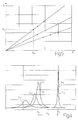
- Figure 4 shows a graph of test data acquired in accordance with the present invention; the x axis shows frequency in GHz, and the y axis the power measurement;
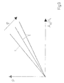
- Figure 5 shows a graph of test data acquired in accordance with the present invention; the x axis shows frequency deviations in GHz, and the y axis power measurement deviations;
- Figure 6 shows a further embodiment of the Figure 3 detail;
- Figure 7 shows a cross section of the Figure 6 detail;
- Figure 8 shows a section of a further embodiment of the Figure 3 detail;
- Figure 9 shows straight lines obtained by linear interpolation of test data obtained measuring tobacco of known density and humidity; the x axis shows the AΔ/Ai ratio, and the y axis density.
- Number 1 in Figure 1 indicates as a whole a packing machine for producing packets of cigarettes. Packing machine 1 comprises a device 2 (Figure 2) for controlling the fill of tips 3 of cigarettes 4.
Device 2 is located downstream from a hopper 5 (shown schematically in Figure 1) for cigarettes 4, and upstream from a reject unit (not shown), and in turn comprises aconveyor 6 forfeeding groups 7 of cigarettes 4, crosswise to cigarettes 4, along a feed path P through acontrol station 8 equipped with acontrol unit 9. -
Conveyor 6 comprises abelt 10; and a number ofseats 11, each for housing arespective group 7 of cigarettes 4 comprising threesuperimposed rows 12 of cigarettes 4. -
Control unit 9 comprises a number of - in particular, three -microwave sensors 13 arranged one on top of another, so that, asgroup 7 of cigarettes 4 travels throughcontrol station 8, eachsensor 13 detects the density of the tips of cigarettes 4 in arespective row 12. - In the Figure 3 embodiment, each
sensor 13 produces a respectivestationary microwave field 14 of given shape, and emits a number of acquisition signals, each depending on the density of a respective tip 3 of cigarette 4 travelling throughmicrowave field 14. More specifically,microwave field 14 is substantially hemispherical. - Each
sensor 13 comprises abody 15 made of conducting material (e.g. aluminium) and having a substantiallycircular groove 16 defining aflat member 17 coated externally with twolayers 17' and 18 of dielectric material (e.g. alumina or plastic), and afurther layer 19 of conducting material. Layer 17' directly contactsflat member 17, and is located on the opposite side oflayer 19 tolayer 18.Flat member 17 is typically about 8 mm in diameter. - Each
sensor 13 also comprises twoelectrodes 20 for connecting layer 17' of dielectric material to a generator 21 and to a detector (not shown) of acomputer 22 respectively. - In actual use, as a
group 7 of cigarettes 4 travels throughcontrol station 8, eachsensor 13 emits a detection signal for each cigarette 4 whose tip 3 travels through therespective microwave field 14. At this point,computer 22 compares the detection signal with a reference data item. More specifically,computer 22 determines a detection data item as a function of the detection signal, and compares the detection data item with the reference data item. If the difference between the detection signal and the reference data item exceeds a given threshold value, an error signal indicating a faulty cigarette 4 is emitted. In which case, the reject unit (not shown) downstream from device 1 and connected tocomputer 22 eliminates the faulty cigarette 4 or (in other embodiments) thegroup 7 containing the faulty cigarette 4. - Operation of
sensor 13 andcomputer 22 will now be explained in more detail with particular reference to Figures 4 and 5. For each measurement,sensor 13 performs a sweep to vary the microwave frequency inmicrowave field 14 between 1 GHz and 300 GHz. Microwave frequency is preferably varied between 2 and 3 GHz to avoid heating the tobacco in cigarettes 4 travelling throughcontrol station 8 and/or any biological tissue inmicrowave field 14. - Figure 4 - in which the y axis shows microwave frequency, and the x axis the power measurement - shows a reference curve CR relative to a reference signal obtained with substantially no objects in
microwave field 14. Reference curve CR has a peak at a given reference frequency AR, and a reference amplitude BR at mid peak height. - Figure 4 also shows response curves Ci, Cii, Ciii of relative detection signals. Each response curve has a relative peak detected frequency Ai, and a relative detected amplitude Bi at mid peak height; which peak detected frequency Ai and detected amplitude Bi depend on the humidity and density of a tip 3 of analyzed cigarette 4.
- In actual use, to determine the fill of tip 3 of cigarette 4,
computer 22 receives the detection signal, and determines peak detected frequency Ai and detected amplitude Bi, which are then processed to permit a comparison between the detection signal and the reference data item. -
Computer 22 preferably determines a first deviation AΔ between peak detected frequency Ai and reference frequency AR, and a second deviation BΔ between detected amplitude Bi and reference amplitude BR. At this point, a detected humidity of tip 3 of cigarette 4 is determined, in particular by means of the following equation:
where ϕ is directly proportional to detected humidity. In this connection, it should be pointed out that, in a test graph showing first deviation AΔ along the x axis, and second deviation BΔ along the y axis (as in Figure 5), the points relative to detection signals of tips 3 of different cigarettes 4 of substantially the same humidity substantially lie on the same straight lines. - Given the detected humidity,
computer 22 determines a detected density of tip 3 of cigarette 4 as a function of detected humidity and of first deviation AΔ or second deviation BΔ. More specifically, density is calculated using curves (in particular, straight lines) T determined beforehand experimentally (and shown in Figure 9). Each curve T defines density (indicated ρ in Figure 9) as a function of ratio AΔ/Ai at a given constant humidity (i.e. a given constant ϕ). - At this point, the detected density (i.e. the detected data item) is compared with a reference density (i.e. the reference data item); and, if the difference between the detected density and the reference density exceeds the threshold value, the error signal is emitted.
- In a further embodiment shown in Figures 6 and 7,
sensor 13 comprises a flatcircular body 23 of dielectric material (e.g. alumina) coated with alayer 24 of conducting material (e.g. copper) having a number ofcircular holes 25. In this case,microwave field 14 is substantially cylindrical. - In a further embodiment shown in Figure 8,
sensor 13 comprises abody 26 of dielectric material (e.g. alumina) coated with alayer 27 of conducting material (e.g. copper) having threecircular holes 28, and three substantially parallelepiped-shaped members 29 of conducting material; andholes 28 are covered with a layer ofinsulating material 30. In this case,sensor 13 defines threemicrowave fields 14, and therefore controls the mean density of three tips 3 of cigarettes 4 simultaneously. - Device 1 has the following advantages:
- cigarettes 4 need not be offset with respect to one another;
- detection signals, and therefore density measurements, independent of tobacco colour are obtained;
- detection signals, and therefore density measurements, sensitive to below-surface tobacco voids are obtained.
Claims (29)
- A device for controlling the fill of cigarette tips, comprising conveying means (6) for feeding a group (7) of cigarettes (4) along a feed path (P) through a control station (8); at least one sensor (13) located at the control station (8), and which emits a detection signal as a function of the fill of a tip (3) of a cigarette (4); and a computer (22) connected to the sensor (13), and which compares the detection signal with a reference data item, and emits an error signal as a function of the comparison between the reference data item and the detection signal; the device being characterized in that the sensor (13) comprises a microwave sensor (13) for producing a microwave field (14) of a substantially given shape, and through which the tip (3) of the cigarette (4) travels in use; the detection signal being a function of the density of the tip (3) of the cigarette (4).
- A device as claimed in Claim 1, wherein the computer (22) determines a detection data item as a function of the detection signal, and emits the error signal when the difference between the detection data item and the reference data item exceeds a threshold value.
- A device as claimed in Claim 1 or 2, wherein the microwave sensor (13) defines a planar microwave field (14).
- A device as claimed in any one of Claims 1 to 3, wherein the conveying means (6) convey the groups (7) of cigarettes (4) crosswise to the cigarettes (4).
- A device as claimed in any one of Claims 1 to 4, wherein the sensor (13) emits a respective detection signal for each cigarette (4) whose tip (3) travels through the microwave field (14).
- A device as claimed in any one of Claims 1 to 5, and comprising at least three sensors (13), each for controlling tips (3) of cigarettes (4) in a respective row (12) of cigarettes (4) in each group (7) of cigarettes (4); each group (7) of cigarettes (4) comprising three superimposed rows (12) of cigarettes (4).
- A device as claimed in any one of Claims 1 to 6, wherein the detection signal comprises a response curve (Ci, Cii, Ciii) having a peak detected frequency (Ai), and a detected amplitude (Bi) at mid peak height; the peak detected frequency (Ai) and the detected amplitude (Bi) being functions of the density and humidity of the tip (3) of the cigarette (4); and the computer (22) comparing the detection signal with the reference data item by processing the peak detected frequency (Ai) and the detected amplitude (Bi).
- A device as claimed in Claim 7, wherein the computer (22) determines a detected density of the tip (3) of the cigarette (4) as a function of the peak detected frequency (Ai) and the detected amplitude (Bi).
- A device as claimed in Claim 8, wherein the computer (22) determines a detected humidity of the tip (3) of the cigarette (4) as a function of the peak detected frequency (Ai) and the detected amplitude (Bi), and determines the detected density as a function of the detected humidity and the peak detected frequency (Ai) or the detected amplitude (Bi).
- A device as claimed in any one of Claims 7 to 9, wherein the computer (22) determines a first deviation (AΔ) between the peak detected frequency (Ai) and a reference frequency (AR), determines a second deviation (BΔ) between the detected amplitude (Bi) and a reference amplitude (BR), and determines a detected humidity of the tip (3) of the cigarette (4) as a function of the first and second deviation (AΔ, BΔ); the reference frequency (AR) and the reference amplitude (BR) being the peak frequency and mid-peak-height amplitude respectively of a reference curve (CR) of a reference signal obtained with substantially no objects in the microwave field (14).
- A device as claimed in Claim 10, wherein the computer (22) determines a detected humidity of the tip (3) of the cigarette (4) as a function of the first and second deviation (AΔ, BΔ), and determines the detected density as a function of the detected humidity and the first or second deviation (AΔ, BΔ).
- A device as claimed in Claim 11, wherein the computer (22) determines the detected humidity of the tip (3) of the cigarette (4) according to the following equation:

where ϕ is directly proportional to the detected humidity, AΔ indicates the modulus of the first deviation, and BΔ indicates the modulus of the second deviation. - A device as claimed in Claim 12, wherein the computer (22) determines the detected density of the tip (3) of the cigarette (4) using test curves (T), each of which is predetermined experimentally at a respective given constant humidity; and each curve (T) describes the density pattern as a function of the ratio AΔ/Ai.
- A device as claimed in any one of Claims 1 to 6, wherein the computer (22) breaks the detection signal down into two components (Ai, Bi), each of which is a function of the humidity and density of the tip (3) of the cigarette (4); determines the detected humidity as a function of the two components (Ai, Bi); and determines the detected density as a function of the detected humidity and at least one of the two components (Ai, Bi).
- A method of controlling the fill of cigarette tips, the method comprising conveying a group (7) of cigarettes (4) along a feed path (P) through a control station (8); determining a detection signal as a function of the fill of a single tip (3) of a cigarette (4); and comparing the detection signal with a reference data item, and emitting an error signal as a function of the comparison between the detection signal and the reference data item; the method being characterized in that the detection signal is determined by producing a microwave field (14) of substantially given shape, through which microwave field (14) the tip (3) of the cigarette (4) travels; the detection signal being a function of the density of the tip (3) of the cigarette (4).
- A method as claimed in Claim 15, wherein an error signal is emitted when the difference between a detection data item, determined as a function of the detection signal, and the reference data item exceeds a threshold value.
- A method as claimed in Claim 15 or 16, wherein the microwave field (14) is a planar microwave field (14).
- A method as claimed in any one of Claims 15 to 17, wherein the cigarettes (4) are conveyed transversely through the control station (8).
- A method as claimed in any one of Claims 15 to 18, wherein the detection signal comprises a response curve (Ci, Cii, Ciii) having a peak detected frequency (Ai), and a detected amplitude (Bi) at mid peak height; the peak detected frequency (Ai) and the detected amplitude (Bi) being functions of the density and humidity of the tip (3) of the cigarette (4); and the detection signal being compared with the reference data item by processing the peak detected frequency (Ai) and the detected amplitude (Bi).
- A method as claimed in Claim 19, wherein a detected density of the tip (3) of the cigarette (4) is determined as a function of the peak detected frequency (Ai) and the detected amplitude (Bi).
- A method as claimed in Claim 20, wherein a detected humidity of the tip (3) of the cigarette (4) is determined as a function of the peak detected frequency (Ai) and the detected amplitude (Bi); the detected density being determined as a function of the detected humidity and the peak detected frequency (Ai) or the detected amplitude (Bi).
- A method as claimed in Claim 20 or 21, wherein a first deviation (AΔ) between the peak detected frequency (Ai) and a reference frequency (AR) is determined; a second deviation (BΔ) between the detected amplitude (Bi) and a reference amplitude (BR) is determined; and the detected density of the tip (3) of the cigarette (4) is determined as a function of the first and second deviation (AΔ, BΔ); the reference frequency (AR) and the reference amplitude (BR) being the peak frequency and mid-peak-height amplitude respectively of a reference curve (CR) of a reference signal obtained with substantially no objects in the microwave field (14).
- A method as claimed in Claim 22, wherein the detected humidity of the tip (3) of the cigarette (4) is determined as a function of the first and second deviation (AΔ, BΔ), and the detected density is determined as a function of the detected humidity and the first or second deviation (AΔ, BΔ).
- A method as claimed in Claim 23, wherein the detected humidity of the tip (3) of the cigarette (4) is determined according to the following equation:

where ϕ is directly proportional to the detected humidity, AΔ indicates the modulus of the first deviation, and BΔ indicates the modulus of the second deviation. - A method as claimed in Claim 23 or 24, wherein the detected density of the tip (3) of the cigarette (4) is determined using test curves (T), each of which is predetermined experimentally at a respective given constant humidity; and each curve (T) describes the density pattern as a function of the ratio AΔ/Ai.
- A method as claimed in any one of Claims 20 to 25, wherein the detected density is compared with the reference data item.
- A method as claimed in Claim 26, wherein an error signal is emitted when the difference between the detected density and the reference data item exceeds a threshold value.
- A method as claimed in any one of Claims 15 to 18, wherein the detection signal is broken down into two components (Ai, Bi), each of which is a function of the humidity and density of the tip (3) of the cigarette (4); the detected humidity is determined as a function of the two components (Ai, Bi); and the detected density is determined as a function of the detected humidity and at least one of the two components (Ai, Bi).
- A packing machine comprising a device (1) for controlling the fill of tips (3) of cigarettes (4), as claimed in one of Claims 1 to 14.
Applications Claiming Priority (1)
| Application Number | Priority Date | Filing Date | Title |
|---|---|---|---|
| IT000602A ITBO20050602A1 (en) | 2005-10-07 | 2005-10-07 | PACKING MACHINE, METHOD AND DEVICE FOR THE CONTROL OF CIGARETTE TIPS |
Publications (1)
| Publication Number | Publication Date |
|---|---|
| EP1772067A1 true EP1772067A1 (en) | 2007-04-11 |
Family
ID=37600785
Family Applications (1)
| Application Number | Title | Priority Date | Filing Date |
|---|---|---|---|
| EP06121932A Withdrawn EP1772067A1 (en) | 2005-10-07 | 2006-10-06 | Packing machine and method and device for controlling cigarette tips |
Country Status (3)
| Country | Link |
|---|---|
| US (1) | US20070079840A1 (en) |
| EP (1) | EP1772067A1 (en) |
| IT (1) | ITBO20050602A1 (en) |
Cited By (3)
| Publication number | Priority date | Publication date | Assignee | Title |
|---|---|---|---|---|
| EP2243385A3 (en) * | 2009-04-21 | 2010-11-24 | HAUNI Maschinenbau AG | Capsule monitoring and capsule position regulation in filters for the tobacco processing industry |
| EP2727480A1 (en) * | 2012-11-06 | 2014-05-07 | JT International S.A. | System and method for assessment of smoking articles |
| IT201800005628A1 (en) * | 2018-05-23 | 2019-11-23 | GROUP FORMING UNIT OF CIGARETTES WITH FILTER, IN WHICH FILTER AT LEAST ONE OBJECT IS DROWNED |
Citations (4)
| Publication number | Priority date | Publication date | Assignee | Title |
|---|---|---|---|---|
| EP0370231A1 (en) * | 1988-11-25 | 1990-05-30 | SASIB S.p.A. | Optical device for checking the cigarette tips |
| EP0889321A1 (en) * | 1997-07-02 | 1999-01-07 | TEWS ELEKTRONIK Dipl.-Ing. Manfred Tews | Moisture and density sensor |
| US20040124853A1 (en) * | 2001-03-15 | 2004-07-01 | Hauni Maschinenbau Ag | Microwave-resonator and measuring device |
| DE202005010375U1 (en) * | 2005-07-01 | 2005-10-20 | Tews Elektronik Dipl.-Ing. Manfred Tews | Method for detecting faulty cigarettes in production facility using proximity sensors applied to the cigarette ends |
Family Cites Families (2)
| Publication number | Priority date | Publication date | Assignee | Title |
|---|---|---|---|---|
| US4326542A (en) * | 1980-01-14 | 1982-04-27 | Philip Morris Incorporated | Firmness control in a cigarette maker |
| ITBO20030470A1 (en) * | 2003-08-01 | 2005-02-02 | Gd Spa | AUTOMATIC MACHINE FOR THE TREATMENT OF ARTICLES AND PROVIDED WITH A POSITION DETECTION DEVICE WITH HALL EFFECT SENSORS. |
-
2005
- 2005-10-07 IT IT000602A patent/ITBO20050602A1/en unknown
-
2006
- 2006-01-27 US US11/341,915 patent/US20070079840A1/en not_active Abandoned
- 2006-10-06 EP EP06121932A patent/EP1772067A1/en not_active Withdrawn
Patent Citations (5)
| Publication number | Priority date | Publication date | Assignee | Title |
|---|---|---|---|---|
| EP0370231A1 (en) * | 1988-11-25 | 1990-05-30 | SASIB S.p.A. | Optical device for checking the cigarette tips |
| EP0889321A1 (en) * | 1997-07-02 | 1999-01-07 | TEWS ELEKTRONIK Dipl.-Ing. Manfred Tews | Moisture and density sensor |
| US20040124853A1 (en) * | 2001-03-15 | 2004-07-01 | Hauni Maschinenbau Ag | Microwave-resonator and measuring device |
| DE202005010375U1 (en) * | 2005-07-01 | 2005-10-20 | Tews Elektronik Dipl.-Ing. Manfred Tews | Method for detecting faulty cigarettes in production facility using proximity sensors applied to the cigarette ends |
| EP1739411A1 (en) * | 2005-07-01 | 2007-01-03 | TEWS ELEKTRONIK Dipl.-Ing. Manfred Tews | Apparatus and method for detecting and removing defective cigarettes |
Cited By (7)
| Publication number | Priority date | Publication date | Assignee | Title |
|---|---|---|---|---|
| EP2243385A3 (en) * | 2009-04-21 | 2010-11-24 | HAUNI Maschinenbau AG | Capsule monitoring and capsule position regulation in filters for the tobacco processing industry |
| EP2243385B1 (en) | 2009-04-21 | 2017-06-14 | Hauni Maschinenbau GmbH | Capsule monitoring in filters for the tobacco processing industry |
| EP2727480A1 (en) * | 2012-11-06 | 2014-05-07 | JT International S.A. | System and method for assessment of smoking articles |
| WO2014072289A1 (en) * | 2012-11-06 | 2014-05-15 | Jt International S. A. | System and method for assessment of smoking articles |
| EA027754B1 (en) * | 2012-11-06 | 2017-08-31 | Джт Интернэшнл С.А. | System and method for assessment of smoking articles |
| IT201800005628A1 (en) * | 2018-05-23 | 2019-11-23 | GROUP FORMING UNIT OF CIGARETTES WITH FILTER, IN WHICH FILTER AT LEAST ONE OBJECT IS DROWNED | |
| WO2019224778A1 (en) * | 2018-05-23 | 2019-11-28 | G.D Società per Azioni | Forming unit for groups of filter cigarettes, in said filter at least one object is embedded |
Also Published As
| Publication number | Publication date |
|---|---|
| US20070079840A1 (en) | 2007-04-12 |
| ITBO20050602A1 (en) | 2007-04-08 |
Similar Documents
| Publication | Publication Date | Title |
|---|---|---|
| RU2480508C2 (en) | Levelling device and loading method of furnace chamber of coke battery | |
| US7793664B2 (en) | Apparatus and method for detection and segregation of faulty cigarettes | |
| US7025348B2 (en) | Method and apparatus for detection of multiple documents in a document scanner using multiple ultrasonic sensors | |
| US7337074B2 (en) | Method and apparatus for determining the mass of portioned units of active substances | |
| EP1440924B1 (en) | An apparatus for detection of multiple documents in a document transport | |
| EP1321903A1 (en) | Apparatus for sensing optical characteristics of a banknote | |
| US9277767B2 (en) | Device for producing cigarettes in the tobacco processing industry and a method therefore | |
| GB2284893A (en) | Calibration of weighing apparatus | |
| TW201534894A (en) | Measuring device and method for detecting the characteristics of an object | |
| RU2000103214A (en) | CIGARETTING MACHINE WITH STRIP CHECK | |
| CA3134804C (en) | Sensor assembly for moving items and related filling machine and methods | |
| CN101625410A (en) | Method and ultrasound sensor for calculating the height of objects on a transport device | |
| CN1276999A (en) | Method and apparatus for testing cigarette tip | |
| US5406376A (en) | Apparatus for testing end portions of rod-shaped articles of the tobacco processing industry | |
| WO2001007351A1 (en) | Plug combiner inspection system and method | |
| CN1967251B (en) | System and method for examining a liquid sample | |
| KR100290690B1 (en) | Method and device for checking confidential documents | |
| KR20190039132A (en) | A measuring device and method for detecting an electrically conductive element of a product, | |
| CN109311331A (en) | A series of printer for being printed on objects | |
| US20070079840A1 (en) | Packing machine and method and device for controlling cigarette tips | |
| US7395641B2 (en) | Method of detecting and rejecting faulty cigarettes | |
| CN1311633C (en) | Capacitive proximity sensor for detecting component belts, component feeding device and method for detecting component belts | |
| JP2001086894A (en) | Detector for cracked egg and automatic selector for egg | |
| EP0690288A2 (en) | Method and device for thickness assessment | |
| US6814082B2 (en) | Apparatus and method for generating information on the characteristics of a fiber rope |
Legal Events
| Date | Code | Title | Description |
|---|---|---|---|
| PUAI | Public reference made under article 153(3) epc to a published international application that has entered the european phase |
Free format text: ORIGINAL CODE: 0009012 |
|
| AK | Designated contracting states |
Kind code of ref document: A1 Designated state(s): AT BE BG CH CY CZ DE DK EE ES FI FR GB GR HU IE IS IT LI LT LU LV MC NL PL PT RO SE SI SK TR |
|
| AX | Request for extension of the european patent |
Extension state: AL BA HR MK YU |
|
| 17P | Request for examination filed |
Effective date: 20071010 |
|
| AKX | Designation fees paid |
Designated state(s): AT BE BG CH CY CZ DE DK EE ES FI FR GB GR HU IE IS IT LI LT LU LV MC NL PL PT RO SE SI SK TR |
|
| 17Q | First examination report despatched |
Effective date: 20080910 |
|
| STAA | Information on the status of an ep patent application or granted ep patent |
Free format text: STATUS: THE APPLICATION IS DEEMED TO BE WITHDRAWN |
|
| 18D | Application deemed to be withdrawn |
Effective date: 20090321 |