EP1771621B1 - Guide roll for a web forming machine and methods for manufacturing and using the corresponding guide roll - Google Patents
Guide roll for a web forming machine and methods for manufacturing and using the corresponding guide roll Download PDFInfo
- Publication number
- EP1771621B1 EP1771621B1 EP05756277A EP05756277A EP1771621B1 EP 1771621 B1 EP1771621 B1 EP 1771621B1 EP 05756277 A EP05756277 A EP 05756277A EP 05756277 A EP05756277 A EP 05756277A EP 1771621 B1 EP1771621 B1 EP 1771621B1
- Authority
- EP
- European Patent Office
- Prior art keywords
- plate
- piece
- protruding shaft
- plate piece
- shell
- Prior art date
- Legal status (The legal status is an assumption and is not a legal conclusion. Google has not performed a legal analysis and makes no representation as to the accuracy of the status listed.)
- Expired - Lifetime
Links
Images


Classifications
-
- D—TEXTILES; PAPER
- D21—PAPER-MAKING; PRODUCTION OF CELLULOSE
- D21G—CALENDERS; ACCESSORIES FOR PAPER-MAKING MACHINES
- D21G1/00—Calenders; Smoothing apparatus
- D21G1/02—Rolls; Their bearings
-
- D—TEXTILES; PAPER
- D21—PAPER-MAKING; PRODUCTION OF CELLULOSE
- D21F—PAPER-MAKING MACHINES; METHODS OF PRODUCING PAPER THEREON
- D21F1/00—Wet end of machines for making continuous webs of paper
- D21F1/36—Guiding mechanisms
- D21F1/40—Rolls
-
- D—TEXTILES; PAPER
- D21—PAPER-MAKING; PRODUCTION OF CELLULOSE
- D21G—CALENDERS; ACCESSORIES FOR PAPER-MAKING MACHINES
- D21G1/00—Calenders; Smoothing apparatus
- D21G1/02—Rolls; Their bearings
- D21G1/0226—Bearings
Definitions
- the present invention relates to a guide roller for a web forming machine, according to the preamble of claim 1.
- the invention also relates to a method for manufacturing and to the use of the guide roll.
- a guide roller according to the preamble of claim 1 is known from US 4,062,098 A .
- the plate piece of this guide roller is parallel to the end plate thereof.
- DE 196 01 844 A1 relates to a paper web guide roller having a body and projecting support elements on both sides as well as means for adjusting the roller body deflection in opposition to deflection resulting from stress to the web.
- a web forming machine for example a paper or board machine.
- Examples are the guide rolls used to support a felt or wire.
- the segment of the guide roll that is covered is usually small, so that it is lightly loaded.
- the shell is made from sheet steel, which is bent and welded. Cast end pieces, which are attached to the shell, are used in a guide roll. In the prior art, the shell is finally machined and the guide roll balanced.
- the known end pieces are made by machining cast pieces.
- the machining requirements determine the construction and dimensioning of the shell and the end piece, even though the loading requirement is small. This makes the guide roll excessively massive and expensive relative to its operating purpose.
- a cast end piece and thin shell are an unsatisfactory combination in terms of vibration.
- deflection also occurs in the sheet construction shell and cannot be compensated for in known guide rolls.
- the invention is intended to create a new type of guide roll for a web forming machine, which is lighter and with a simpler construction than previously.
- the invention is also intended to create a new type of method for manufacturing a guide roll intended for a web forming machine, which method is simple and which easily creates new properties in the guide roll.
- the guide roll according to the invention there is a new type of shell and end-piece construction, so that a simple and economical guide roll is created.
- the use of the manufacturing method permits a considerable reduction in costs, while keeping the properties of the guide roll at least at the previous level.
- properties that increase the usability and manufacturability of the guide roll can be incorporated in the guide roll.
- the guide roll according to the invention can be used in a new and surprising manner, in which case the deflection of the guide roll, for example, can be brought under control. At the same time, the guide roll can be rotated at higher rotation speeds than previously.
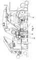
- Figure 1 shows a side view of the press section of a web forming machine.
- the web forming machine is a paper or board machine, in which the guide roll is used in various positions.
- the embodiment of Figure 1 also include two paper guide rolls 15, which also have their own drives.
- the guide roll 15' according to the invention can also be used in connection with the fabric ( figure 1 ). Later the guide roll is referred to more simply as the roll.
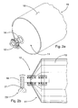
- the roll 15 includes a shell 10 of sheet material and end pieces 11 at both ends, to support the roll 15 rotatably in bearing arrangement 12 ( Figure 2a ).
- the shell can also incorporate surface treatment or a cover.
- the end pieces 11 also have a protruding shaft 14 for the bearing arrangement 12.
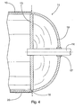
- Figures 3 and 4 partly show a cross-section of a roll according to the invention.
- the end plate 13 and protruding shaft 14 belonging to the end piece 11 are arranged as a separate piece.
- at least one shaped plate piece 19 is fitted separately in the axial direction at the point of contact of the end plate 13 and the protruding shaft 14.
- the plate piece 19 is arranged in such a way that its inner edge or edge area in a radial direction is attached to the protruding shaft 14 and the radially outer edge or edge area is attached to the end plate 13, or to the shell, or to both, either directly or through an intermediate piece/intermediate pieces.
- the various part of the end piece can be manufactured separately, which will avoid the casting and machining of large pieces.
- the parts can even be made in different ways and from different materials.
- thinner materials than previously can be used.
- by using a plate piece at the end of the roll a stiff but light cell construction is formed, which can be easily support by the protruding shaft. At the same time, the deflection of the protruding shaft will be less than previously.
- the end plate 13 and the protruding shaft 14 are separately machined bodies of revolution.
- the protruding shaft is a cast piece, which is machined.
- the end plate can even be of a sheet material, in which there is a hole for the protruding shaft. The manufacture of the separate pieces is simple and they can be dimensioned precisely for each operating purpose.
- FIGs 3 and 4 show a unified plate piece 19 with a curved shape, which like the shell 10 is made from a thin sheet material. The desired shapes can then be easily obtained in the structures, while new methods can be used to attache the pieces.
- the protruding shaft 14 is preferably fitted to the end plate 13 using a shrink joint. In that case the positioning between them will be retained precisely and, if necessary, the protruding shaft can even be replaced.
- the attachment of the plate piece 19 to the protruding shaft 14 is ensured by welding, which is shown by the arrow in Figure 3 . The actual moment is transmitted through the aforesaid force-fit joint.
- the plate piece according to the invention is curved or conical.
- a conical plate piece 19 is shown in Figure 5 .
- the same reference numbers are used for components that are functionally similar. Besides its shape, the position of the plate piece can also vary in different embodiments.
- the shaped plate piece 19 is arranged to open out away form the opposing end piece.
- the plate piece 19 opens out towards the opposing end piece.
- the plate piece is inside the shell, so that the total length of the roll is as short as possible. This allows the roll to be fitted even in cramped positions.
- the plate piece in the embodiment of Figure 4 is a continuation of the shell, so that the free length of the protruding shaft is as short as possible. This avoids detrimental deflection of the protruding shaft.
- Figure 4 also shows an attachment collar 17, to which the protruding shaft 14 is attached by a force-fit joint, welded to the plate piece.
- the attachment collar described above can also be used in the embodiment of Figure 5 .
- the conical plate piece 19 is fitted directly to the protruding shaft 14.
- a damping and/or insulating material 24' can be arranged in the space delimited by the shell 10 and the end pieces 11. The shell will then certainly remain round and the material will effectively prevent vibration in the shall.
- the material used is, for example, styrox, cellular plastic, or some other relatively light material.
- a cellular structure is light, but is sufficiently stiff to achieve damping.
- a damping and/or insulating material 24 can also be arranged in the space delimited by the end plate 13 and the plate piece 19. The material will further increase the stiffness of the conical triangular cell, which will also reduce the vibration of the roll.
- the material is installed from solid pieces during the manufacture of the roll, or it can be, for example, extruded into the finished roll.
- the diameter of a roll according to the invention is usually less than 500 mm.
- the plate piece 19 is roll-formed and/or deep-drawn from a thin-sheet material.
- the plate piece can be made from a single blank, in which case the plate piece will be seamless.
- a roll-formed or deep-drawn plate piece will also retain its shape well, which will further improve the stiffness of the roll.
- the plate piece can be made from one or more pieces by welding.
- the cast components, for example, the protruding shaft, are made by traditional methods by casting and machining. In the manufacture of the shell and plate piece, on the other hand, laser cutting is used in addition to the above shaping methods.
- the sheet material can also be laser-welded with good results.
- the plate piece is indeed attached to the shell and end plate by laser-welding.
- the locking weld between the protruding shaft and the plate piece can also be made using a laser.
- the weld point is shown by the small arrow in Figures 3 - 5 .
- the use of laser-cutting and welding is an easy way to give the roll accurate dimensions and shape.
- the roll is thus ready-to-use without machining.
- the circularity of the roll can be arranged as desired by covering the shell 10.
- the cover 20 is shown in Figure 4 .
- grooves for example, can be machined in the cover, the shape and dimensions of which can be selected as required.
- Other machining of the roll is usually unnecessary, as the seam formed by laser-welding without a filler is very smooth.
- the new type of end piece also makes it possible to use bearing arrangement that differ from those known.
- the bearing arrangement 12 are attached either to the protruding shaft 14, or to the plate piece 19.
- the bearing arrangement can also be attached to both the plate piece 19 and the end plate 13.
- the protruding shaft 14 is attached to the end piece 11, in which case the bearing arrangement 12 are attached to the protruding shaft 14 according to Figure 2a .
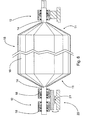
- the bearing arrangement in question is also shown in the right-hand end part of the roll of Figure 6 .
- the protruding shaft 14 does not rotate, so that the bearing arrangement 12 are in either the plate pieace or the end plate, or in both.
- the bearing arrangement 12 at least two bearings 18 are arranged, which are fitted at a distance to each other in the axial direction, in order to create support surfaces.
- the necessary support surface can be created easily by using two simple bearings.
- a corresponding rocker element could also be fitted at the other end of the roll, but a change of angle in the protruding shaft can be achieved using a single special bearing.
- the roll according to the invention is light, but stiff.
- the manufacture of the roll is simpler and more economical than previously.
- the specific frequency of the roll increases, so that it sensitivity to vibration decreases.
- the protruding shaft can be selected more freely, permitting the use of shaft diameters that are smaller than previously.
- the bearings can be selected more freely. Damping can also be arranged in the roll and the end piece. In addition, even the deflection of the roll can be compensated.
Landscapes
- Rolls And Other Rotary Bodies (AREA)
- Bending Of Plates, Rods, And Pipes (AREA)
- Registering, Tensioning, Guiding Webs, And Rollers Therefor (AREA)
Abstract
Description
- The present invention relates to a guide roller for a web forming machine, according to the preamble of claim 1.
- The invention also relates to a method for manufacturing and to the use of the guide roll.
- A guide roller according to the preamble of claim 1 is known from
US 4,062,098 A . The plate piece of this guide roller is parallel to the end plate thereof. -
DE 196 01 844 A1 relates to a paper web guide roller having a body and projecting support elements on both sides as well as means for adjusting the roller body deflection in opposition to deflection resulting from stress to the web. - Numerous guide rolls are used in a web forming machine, for example a paper or board machine. Examples are the guide rolls used to support a felt or wire. The segment of the guide roll that is covered is usually small, so that it is lightly loaded. In addition, in a web forming machine there are special paper guide rolls, over which only the paper is transported. In that case, the linear load on the paper guide roll will be in the order of 1 kN/m. In known guide rolls, the shell is made from sheet steel, which is bent and welded. Cast end pieces, which are attached to the shell, are used in a guide roll. In the prior art, the shell is finally machined and the guide roll balanced.
- The known end pieces are made by machining cast pieces. In practice, the machining requirements determine the construction and dimensioning of the shell and the end piece, even though the loading requirement is small. This makes the guide roll excessively massive and expensive relative to its operating purpose. In addition, a cast end piece and thin shell are an unsatisfactory combination in terms of vibration. In practice, deflection also occurs in the sheet construction shell and cannot be compensated for in known guide rolls.
- The invention is intended to create a new type of guide roll for a web forming machine, which is lighter and with a simpler construction than previously. The invention is also intended to create a new type of method for manufacturing a guide roll intended for a web forming machine, which method is simple and which easily creates new properties in the guide roll.
- The characteristic features of the guide roll according to the present invention appear in the accompanying Claim 1. Correspondingly, the characteristic features of the manufacturing method according to the invention appear in the accompanying
Claim 10. - In the guide roll according to the invention, there is a new type of shell and end-piece construction, so that a simple and economical guide roll is created. In addition, the use of the manufacturing method permits a considerable reduction in costs, while keeping the properties of the guide roll at least at the previous level. On the other hand, properties that increase the usability and manufacturability of the guide roll can be incorporated in the guide roll. In addition, the guide roll according to the invention can be used in a new and surprising manner, in which case the deflection of the guide roll, for example, can be brought under control. At the same time, the guide roll can be rotated at higher rotation speeds than previously.
- In the following, the invention is examined in detail with reference to the accompanying drawings showing embodiments of the invention, in which
- Figure 1
- shows the paper guide roll according to the invention fitted to the press section of a web forming machine,
- Figure 2a
- shows an axonometric view of part of the guide roll according to the invention,
- Figure 2b
- shows a schematic drawing of the end component of the guide roll according to the invention,
- Figure 3
- shows a schematic drawing of a cross-section of a second embodiment of the end component of the guide roll according to the invention,
- Figure 4
- shows a schematic drawing of a cross-section of a third embodiment of the end component of the guide roll according to the invention,
- Figure 5
- shows a schematic drawing of a partial cross-section of a fourth embodiment of the end component of the guide roll according to the invention,
- Figure 6
- shows a schematic drawing of a support embodiment of the guide roll according to the invention.
-
Figure 1 shows a side view of the press section of a web forming machine. Usually the web forming machine is a paper or board machine, in which the guide roll is used in various positions. The embodiment ofFigure 1 also include twopaper guide rolls 15, which also have their own drives. The guide roll 15' according to the invention can also be used in connection with the fabric (figure 1 ). Later the guide roll is referred to more simply as the roll. Generally theroll 15 includes ashell 10 of sheet material andend pieces 11 at both ends, to support theroll 15 rotatably in bearing arrangement 12 (Figure 2a ). The shell can also incorporate surface treatment or a cover. Theend pieces 11 also have a protrudingshaft 14 for thebearing arrangement 12. -
Figures 3 and4 partly show a cross-section of a roll according to the invention. According to the invention, theend plate 13 and protrudingshaft 14 belonging to theend piece 11 are arranged as a separate piece. In addition, between theend plate 13 and theprotruding shaft 14 at least oneshaped plate piece 19 is fitted separately in the axial direction at the point of contact of theend plate 13 and theprotruding shaft 14. In other words, theplate piece 19 is arranged in such a way that its inner edge or edge area in a radial direction is attached to theprotruding shaft 14 and the radially outer edge or edge area is attached to theend plate 13, or to the shell, or to both, either directly or through an intermediate piece/intermediate pieces. Thus the various part of the end piece can be manufactured separately, which will avoid the casting and machining of large pieces. In addition, the parts can even be made in different ways and from different materials. At the same time, thinner materials than previously can be used. In addition, by using a plate piece at the end of the roll a stiff but light cell construction is formed, which can be easily support by the protruding shaft. At the same time, the deflection of the protruding shaft will be less than previously. - In the lightly-loaded roll according to the invention, it is possible to use a
simple protruding shaft 14, which can be supported in many different ways. InFigures 3 and4 , theend plate 13 and theprotruding shaft 14 are separately machined bodies of revolution. In this case, the protruding shaft is a cast piece, which is machined. On the other hand, the end plate can even be of a sheet material, in which there is a hole for the protruding shaft. The manufacture of the separate pieces is simple and they can be dimensioned precisely for each operating purpose. - The construction of the plate piece can vary in different embodiments.
Figures 3 and4 show aunified plate piece 19 with a curved shape, which like theshell 10 is made from a thin sheet material. The desired shapes can then be easily obtained in the structures, while new methods can be used to attache the pieces. According to the invention, there is a force-fit joint between theend plate 13 and the protrudingshaft 14. In practice, the protrudingshaft 14 is preferably fitted to theend plate 13 using a shrink joint. In that case the positioning between them will be retained precisely and, if necessary, the protruding shaft can even be replaced. In the embodiment ofFigure 3 , the attachment of theplate piece 19 to the protrudingshaft 14 is ensured by welding, which is shown by the arrow inFigure 3 . The actual moment is transmitted through the aforesaid force-fit joint. - The plate piece according to the invention is curved or conical. A
conical plate piece 19 is shown inFigure 5 . The same reference numbers are used for components that are functionally similar. Besides its shape, the position of the plate piece can also vary in different embodiments. InFigure 3 , the shapedplate piece 19 is arranged to open out away form the opposing end piece. Correspondingly inFigure 4 theplate piece 19 opens out towards the opposing end piece. In the embodiment ofFigure 3 , the plate piece is inside the shell, so that the total length of the roll is as short as possible. This allows the roll to be fitted even in cramped positions. The plate piece in the embodiment ofFigure 4 , on the other hand, is a continuation of the shell, so that the free length of the protruding shaft is as short as possible. This avoids detrimental deflection of the protruding shaft. - Besides using a separate protruding shaft and plate piece, the different components are attached to each other in a new way. According to the invention, at the point where the
shell 10, theend plate 13, and theplate piece 19 come together, there is aweld 16, which is made from outside theshell 10 from the point shown by the arrow. InFigure 3 , theplate piece 19 is attached to the inner surface of theshell 10. In addition to this, theend plate 13 is set onto both theshell 10 and theplate piece 19. Thus, by welding at the point shown by the arrow, all three pieces are attached to each other rapidly and simply. In other words, theshell 10, theend plate 13, and theplate piece 19 are welded together simultaneously. The same principle is also realized inFigure 4 , in which theplate piece 19 is end-on to theshell 10. In this case, theend plate 13 is at the intersection of theshell 10 and theplate piece 19, so that theweld 16 attaches the pieces securely to each other.Figure 4 also shows anattachment collar 17, to which the protrudingshaft 14 is attached by a force-fit joint, welded to the plate piece. - The attachment collar described above can also be used in the embodiment of
Figure 5 . In that case, theconical plate piece 19 is fitted directly to the protrudingshaft 14. According to the invention, in addition a damping and/or insulating material 24' can be arranged in the space delimited by theshell 10 and theend pieces 11. The shell will then certainly remain round and the material will effectively prevent vibration in the shall. The material used is, for example, styrox, cellular plastic, or some other relatively light material. A cellular structure is light, but is sufficiently stiff to achieve damping. A damping and/or insulatingmaterial 24 can also be arranged in the space delimited by theend plate 13 and theplate piece 19. The material will further increase the stiffness of the conical triangular cell, which will also reduce the vibration of the roll. The material is installed from solid pieces during the manufacture of the roll, or it can be, for example, extruded into the finished roll. - The diameter of a roll according to the invention is usually less than 500 mm. According to the invention, the
plate piece 19 is roll-formed and/or deep-drawn from a thin-sheet material. In practice, the plate piece can be made from a single blank, in which case the plate piece will be seamless. A roll-formed or deep-drawn plate piece will also retain its shape well, which will further improve the stiffness of the roll. On the other hand, the plate piece can be made from one or more pieces by welding. The cast components, for example, the protruding shaft, are made by traditional methods by casting and machining. In the manufacture of the shell and plate piece, on the other hand, laser cutting is used in addition to the above shaping methods. In will then be possible to use even a thin-sheet material with a thickness of less than 5 mm. In addition to its ease of shaping, the sheet material can also be laser-welded with good results. According to the invention, the plate piece is indeed attached to the shell and end plate by laser-welding. The locking weld between the protruding shaft and the plate piece can also be made using a laser. The weld point is shown by the small arrow inFigures 3 - 5 . - The use of laser-cutting and welding is an easy way to give the roll accurate dimensions and shape. The roll is thus ready-to-use without machining. If necessary, the circularity of the roll can be arranged as desired by covering the
shell 10. Thecover 20 is shown inFigure 4 . At the same time, grooves, for example, can be machined in the cover, the shape and dimensions of which can be selected as required. Other machining of the roll is usually unnecessary, as the seam formed by laser-welding without a filler is very smooth. - The new type of end piece also makes it possible to use bearing arrangement that differ from those known. According to the invention, the bearing
arrangement 12 are attached either to the protrudingshaft 14, or to theplate piece 19. On the other hand, the bearing arrangement can also be attached to both theplate piece 19 and theend plate 13. InFigure 3 and4 , the protrudingshaft 14 is attached to theend piece 11, in which case the bearingarrangement 12 are attached to the protrudingshaft 14 according toFigure 2a . The bearing arrangement in question is also shown in the right-hand end part of the roll ofFigure 6 . InFigure 2b , on the other hand, the protrudingshaft 14 does not rotate, so that the bearingarrangement 12 are in either the plate pieace or the end plate, or in both. By arranging at least two support surfaces in thebearing arrangement 12 of at least oneend piece 11, it is possible to turn thebearing arrangement 12 or the protrudingshaft 14 to compensate for deflection in the roll. InFigure 2b , thenonrotating protruding shaft 14 is turned, so that the alignment of the roll can be changed. In this case, the turning takes place relative to only asingle pivot point 21, but if necessary several degrees of freedom can be arranged in the support and turning and the necessary movements implemented using suitable elements and devices (not shown). - In practice, in the
bearing arrangement 12 at least twobearings 18 are arranged, which are fitted at a distance to each other in the axial direction, in order to create support surfaces. Thus the necessary support surface can be created easily by using two simple bearings. In the left-hand end of the roll ofFigure 6 , there are twobearings 18, which are supported by arocker element 23 in the structures of the web forming machine. A corresponding rocker element could also be fitted at the other end of the roll, but a change of angle in the protruding shaft can be achieved using a single special bearing. - In its entirety, the roll according to the invention is light, but stiff. In addition, the manufacture of the roll is simpler and more economical than previously. Similarly, the specific frequency of the roll increases, so that it sensitivity to vibration decreases. In addition, the protruding shaft can be selected more freely, permitting the use of shaft diameters that are smaller than previously. At the same time, the bearings can be selected more freely. Damping can also be arranged in the roll and the end piece. In addition, even the deflection of the roll can be compensated.
Claims (13)
- Guide roller (15,15') for a web forming machine, comprising- a shell (10) of a sheet material,- an end pieces (11) attached to both ends of the shell (10) respectively, suitable for supporting the guide roller (15, 15') rotatably in bearing arrangements (12) in the web forming machine, wherein said end piece (11) is assembled from separate pieces, comprising- an end plate (13)- a protruding shaft (14), and- at least one shaped plate piece (19), wherein- the protruding shaft (14) for the bearing is arranged in the end plate (13), and- between the end plate (13) and the protruding shaft (14) the at least one shaped plate piece (19) is fitted separately,
characterized in that the points of contact of the shaped plate piece (19) with the end plate (13) and with the protruding shaft (14) are spaced in the axial direction, and in that the plate piece (19) is curved or conical such that the plate piece (19) opens out away from or towards the opposing end piece. - Guide roller according to Claim 1, characterized in that the end plate (13) and the protruding shaft (14) are separately machined bodies of revolution.
- Guide roller according to Claim 1 or 2, characterized in that the shell (10) and the plate piece (19) are of a thin sheet material.
- Guide roller according to any of Claims 1 - 3, characterized in that there is a force-fit joint between the end plate (13) and the protruding shaft (14).
- Guide roller according to any of Claims 1 - 4, characterized in that at the point where the shell (10), the end plate (13), and the plate piece (19) come together there is a weld (16), to attach the shell (10), the end plate (13), and the plate piece (19) to each other.
- Guide roller according to any of Claims 1 - 5, characterized in that damping and/or insulating material (24) is arranged in the space delimited by the shell (10) and the end pieces (11).
- Guide roller according to any of Claims 1 - 6, characterized in that damping and/or insulating material (24) is arranged in the space delimited by the end plate (13) and the plate piece (19).
- Use of a guide roller (15) according to any of Claims 1 - 7, in which the guide roller (15) is a roll in contact with the paper.
- Use of a guide roller according to any of Claims 1 - 7, in which the guide roller (15) is a roll in contact with a fabric.
- Method for manufacturing a guide roller for a web forming machine, in which method- a shell (10) is made from a sheet material,- end pieces (11) are made, each of which comprises an end plate (13), a protruding shaft (14) for a bearing arrangement (12) and a shaped plate piece (10), and- the end pieces (11) are attached to both ends of the shell (10), respectively, wherein the end plate (13) and the protruding shaft (14) are arranged as separate pieces and are connected by at least one shaped plate piece (19), in order to form a cell construction,
characterized in that the points of contact of the shaped plate piece (19) with the end plate (13) and with the protruding shaft (14) are spaced in the axial direction, and in that the plate piece (19) is curved or conical such that the plate piece (19) opens out away from or towards the opposing end piece. - Method according to Claim 10, characterized in that the shell (10), end plate (13), and plate piece (19) are simultaneously welded to each other.
- Method according to Claim 10 or 11, characterized in that the plate piece (19) is of a roll-shaped and/or deep-drawn thin-sheet material, or it is manufactured from one or several parts by welding.
- Method according to any of Claims 10 - 12, characterized in that the bearing arrangement (12) is attached to either the protruding shaft (14) or the plate piece (19), or to the plate piece (19) and the end plate (13).
Applications Claiming Priority (2)
| Application Number | Priority Date | Filing Date | Title |
|---|---|---|---|
| FI20045279A FI117640B (en) | 2004-07-28 | 2004-07-28 | Guide roll for a forming machine and methods for making and using the corresponding guide roll |
| PCT/FI2005/050230 WO2006010792A2 (en) | 2004-07-28 | 2005-06-22 | Guide roll for a web forming machine and methods for manufacturing and using the corresponding guide roll |
Publications (2)
| Publication Number | Publication Date |
|---|---|
| EP1771621A2 EP1771621A2 (en) | 2007-04-11 |
| EP1771621B1 true EP1771621B1 (en) | 2011-09-14 |
Family
ID=32749270
Family Applications (1)
| Application Number | Title | Priority Date | Filing Date |
|---|---|---|---|
| EP05756277A Expired - Lifetime EP1771621B1 (en) | 2004-07-28 | 2005-06-22 | Guide roll for a web forming machine and methods for manufacturing and using the corresponding guide roll |
Country Status (5)
| Country | Link |
|---|---|
| EP (1) | EP1771621B1 (en) |
| CN (1) | CN1989293B (en) |
| AT (1) | ATE524603T1 (en) |
| FI (1) | FI117640B (en) |
| WO (1) | WO2006010792A2 (en) |
Family Cites Families (5)
| Publication number | Priority date | Publication date | Assignee | Title |
|---|---|---|---|---|
| NL178443C (en) * | 1975-12-02 | 1986-03-17 | Brugman Machinefabriek Bv | GUIDE ROLLER. |
| DE19601844A1 (en) * | 1996-01-19 | 1997-07-24 | Voith Sulzer Finishing Gmbh | Paper web guide roller for use in paper production, e.g. in calendar |
| DE19647919A1 (en) * | 1996-11-20 | 1998-05-28 | Voith Sulzer Papiermasch Gmbh | Moving paper or cardboard web guide |
| FI103071B (en) * | 1997-08-19 | 1999-04-15 | Valmet Corp | Bendable roll for web-like material |
| DE10341119A1 (en) * | 2003-09-05 | 2005-03-31 | Voith Paper Patent Gmbh | Spreader roll |
-
2004
- 2004-07-28 FI FI20045279A patent/FI117640B/en not_active IP Right Cessation
-
2005
- 2005-06-22 WO PCT/FI2005/050230 patent/WO2006010792A2/en not_active Ceased
- 2005-06-22 AT AT05756277T patent/ATE524603T1/en active
- 2005-06-22 EP EP05756277A patent/EP1771621B1/en not_active Expired - Lifetime
- 2005-06-22 CN CN2005800243619A patent/CN1989293B/en not_active Expired - Fee Related
Also Published As
| Publication number | Publication date |
|---|---|
| ATE524603T1 (en) | 2011-09-15 |
| FI117640B (en) | 2006-12-29 |
| WO2006010792A2 (en) | 2006-02-02 |
| FI20045279A0 (en) | 2004-07-28 |
| WO2006010792A3 (en) | 2006-05-04 |
| CN1989293A (en) | 2007-06-27 |
| FI20045279L (en) | 2006-01-29 |
| EP1771621A2 (en) | 2007-04-11 |
| CN1989293B (en) | 2010-11-10 |
Similar Documents
| Publication | Publication Date | Title |
|---|---|---|
| US7824320B2 (en) | Expander roller | |
| US7867155B2 (en) | Expander roller | |
| JP2010529386A (en) | Balancing shaft | |
| FI103071B (en) | Bendable roll for web-like material | |
| JPH038805Y2 (en) | ||
| US4715731A (en) | Gas bearing | |
| KR960702891A (en) | ADJUSTABLE BEARING FOR THE SHELL OF A DEFLECTION ROLL | |
| FI121825B (en) | Distribution Selection | |
| DE102004045407A1 (en) | Roller to spread out a web, in a papermaking/cardboard production/finishing machine, has the outer mantle supported at the ends by bushes and bearings at support structures with position adjustment | |
| KR20060018810A (en) | Spreader roll | |
| EP1771621A2 (en) | Guide roll for a web forming machine and methods for manufacturing and using the corresponding guide roll | |
| US20020183180A1 (en) | Roll | |
| FI114563B (en) | Tubular roller for a paper machine | |
| US5960715A (en) | Ink duct for rotary printing presses | |
| EP1027544B1 (en) | Method for producing a bending-resistant, elongated body and an arrangement for a bending-resistant, elongated body | |
| JP2002031128A (en) | Bendable roll having composite shell | |
| CZ291414B6 (en) | Cylinder, particularly rotary printing-machine cylinder for guiding sheets therein | |
| JP3838317B2 (en) | Split backup roll for rolling mill | |
| FI117013B (en) | Roll for use with a drying section in a forming machine | |
| CA2224221C (en) | A bearing arrangement and a coupling element of a spreading roll | |
| FI113071B (en) | Calendar | |
| US6029365A (en) | Machine for producing a sheet | |
| FI117641B (en) | Roll for a forming machine and process for making the corresponding roll | |
| CA2285321A1 (en) | Guiding roller for web material | |
| FI102560B (en) | Bending roll for web-like material |
Legal Events
| Date | Code | Title | Description |
|---|---|---|---|
| PUAI | Public reference made under article 153(3) epc to a published international application that has entered the european phase |
Free format text: ORIGINAL CODE: 0009012 |
|
| 17P | Request for examination filed |
Effective date: 20070111 |
|
| AK | Designated contracting states |
Kind code of ref document: A2 Designated state(s): AT BE BG CH CY CZ DE DK EE ES FI FR GB GR HU IE IS IT LI LT LU MC NL PL PT RO SE SI SK TR |
|
| DAX | Request for extension of the european patent (deleted) | ||
| 17Q | First examination report despatched |
Effective date: 20100407 |
|
| GRAP | Despatch of communication of intention to grant a patent |
Free format text: ORIGINAL CODE: EPIDOSNIGR1 |
|
| GRAS | Grant fee paid |
Free format text: ORIGINAL CODE: EPIDOSNIGR3 |
|
| GRAA | (expected) grant |
Free format text: ORIGINAL CODE: 0009210 |
|
| AK | Designated contracting states |
Kind code of ref document: B1 Designated state(s): AT BE BG CH CY CZ DE DK EE ES FI FR GB GR HU IE IS IT LI LT LU MC NL PL PT RO SE SI SK TR |
|
| REG | Reference to a national code |
Ref country code: GB Ref legal event code: FG4D |
|
| REG | Reference to a national code |
Ref country code: CH Ref legal event code: EP |
|
| REG | Reference to a national code |
Ref country code: IE Ref legal event code: FG4D |
|
| REG | Reference to a national code |
Ref country code: DE Ref legal event code: R096 Ref document number: 602005030037 Country of ref document: DE Effective date: 20111103 |
|
| REG | Reference to a national code |
Ref country code: NL Ref legal event code: VDEP Effective date: 20110914 |
|
| PG25 | Lapsed in a contracting state [announced via postgrant information from national office to epo] |
Ref country code: FI Free format text: LAPSE BECAUSE OF FAILURE TO SUBMIT A TRANSLATION OF THE DESCRIPTION OR TO PAY THE FEE WITHIN THE PRESCRIBED TIME-LIMIT Effective date: 20110914 Ref country code: LT Free format text: LAPSE BECAUSE OF FAILURE TO SUBMIT A TRANSLATION OF THE DESCRIPTION OR TO PAY THE FEE WITHIN THE PRESCRIBED TIME-LIMIT Effective date: 20110914 Ref country code: SE Free format text: LAPSE BECAUSE OF FAILURE TO SUBMIT A TRANSLATION OF THE DESCRIPTION OR TO PAY THE FEE WITHIN THE PRESCRIBED TIME-LIMIT Effective date: 20110914 |
|
| LTIE | Lt: invalidation of european patent or patent extension |
Effective date: 20110914 |
|
| PG25 | Lapsed in a contracting state [announced via postgrant information from national office to epo] |
Ref country code: GR Free format text: LAPSE BECAUSE OF FAILURE TO SUBMIT A TRANSLATION OF THE DESCRIPTION OR TO PAY THE FEE WITHIN THE PRESCRIBED TIME-LIMIT Effective date: 20111215 Ref country code: SI Free format text: LAPSE BECAUSE OF FAILURE TO SUBMIT A TRANSLATION OF THE DESCRIPTION OR TO PAY THE FEE WITHIN THE PRESCRIBED TIME-LIMIT Effective date: 20110914 Ref country code: CY Free format text: LAPSE BECAUSE OF FAILURE TO SUBMIT A TRANSLATION OF THE DESCRIPTION OR TO PAY THE FEE WITHIN THE PRESCRIBED TIME-LIMIT Effective date: 20110914 |
|
| PG25 | Lapsed in a contracting state [announced via postgrant information from national office to epo] |
Ref country code: BE Free format text: LAPSE BECAUSE OF FAILURE TO SUBMIT A TRANSLATION OF THE DESCRIPTION OR TO PAY THE FEE WITHIN THE PRESCRIBED TIME-LIMIT Effective date: 20110914 |
|
| PG25 | Lapsed in a contracting state [announced via postgrant information from national office to epo] |
Ref country code: IS Free format text: LAPSE BECAUSE OF FAILURE TO SUBMIT A TRANSLATION OF THE DESCRIPTION OR TO PAY THE FEE WITHIN THE PRESCRIBED TIME-LIMIT Effective date: 20120114 Ref country code: CZ Free format text: LAPSE BECAUSE OF FAILURE TO SUBMIT A TRANSLATION OF THE DESCRIPTION OR TO PAY THE FEE WITHIN THE PRESCRIBED TIME-LIMIT Effective date: 20110914 Ref country code: SK Free format text: LAPSE BECAUSE OF FAILURE TO SUBMIT A TRANSLATION OF THE DESCRIPTION OR TO PAY THE FEE WITHIN THE PRESCRIBED TIME-LIMIT Effective date: 20110914 |
|
| PG25 | Lapsed in a contracting state [announced via postgrant information from national office to epo] |
Ref country code: PL Free format text: LAPSE BECAUSE OF FAILURE TO SUBMIT A TRANSLATION OF THE DESCRIPTION OR TO PAY THE FEE WITHIN THE PRESCRIBED TIME-LIMIT Effective date: 20110914 Ref country code: NL Free format text: LAPSE BECAUSE OF FAILURE TO SUBMIT A TRANSLATION OF THE DESCRIPTION OR TO PAY THE FEE WITHIN THE PRESCRIBED TIME-LIMIT Effective date: 20110914 Ref country code: EE Free format text: LAPSE BECAUSE OF FAILURE TO SUBMIT A TRANSLATION OF THE DESCRIPTION OR TO PAY THE FEE WITHIN THE PRESCRIBED TIME-LIMIT Effective date: 20110914 Ref country code: PT Free format text: LAPSE BECAUSE OF FAILURE TO SUBMIT A TRANSLATION OF THE DESCRIPTION OR TO PAY THE FEE WITHIN THE PRESCRIBED TIME-LIMIT Effective date: 20120116 Ref country code: RO Free format text: LAPSE BECAUSE OF FAILURE TO SUBMIT A TRANSLATION OF THE DESCRIPTION OR TO PAY THE FEE WITHIN THE PRESCRIBED TIME-LIMIT Effective date: 20110914 Ref country code: IT Free format text: LAPSE BECAUSE OF FAILURE TO SUBMIT A TRANSLATION OF THE DESCRIPTION OR TO PAY THE FEE WITHIN THE PRESCRIBED TIME-LIMIT Effective date: 20110914 |
|
| PLBE | No opposition filed within time limit |
Free format text: ORIGINAL CODE: 0009261 |
|
| STAA | Information on the status of an ep patent application or granted ep patent |
Free format text: STATUS: NO OPPOSITION FILED WITHIN TIME LIMIT |
|
| PG25 | Lapsed in a contracting state [announced via postgrant information from national office to epo] |
Ref country code: DK Free format text: LAPSE BECAUSE OF FAILURE TO SUBMIT A TRANSLATION OF THE DESCRIPTION OR TO PAY THE FEE WITHIN THE PRESCRIBED TIME-LIMIT Effective date: 20110914 |
|
| 26N | No opposition filed |
Effective date: 20120615 |
|
| REG | Reference to a national code |
Ref country code: DE Ref legal event code: R097 Ref document number: 602005030037 Country of ref document: DE Effective date: 20120615 |
|
| PG25 | Lapsed in a contracting state [announced via postgrant information from national office to epo] |
Ref country code: MC Free format text: LAPSE BECAUSE OF NON-PAYMENT OF DUE FEES Effective date: 20120630 |
|
| REG | Reference to a national code |
Ref country code: CH Ref legal event code: PL |
|
| REG | Reference to a national code |
Ref country code: CH Ref legal event code: PL |
|
| GBPC | Gb: european patent ceased through non-payment of renewal fee |
Effective date: 20120622 |
|
| REG | Reference to a national code |
Ref country code: IE Ref legal event code: MM4A |
|
| REG | Reference to a national code |
Ref country code: FR Ref legal event code: ST Effective date: 20130228 |
|
| PG25 | Lapsed in a contracting state [announced via postgrant information from national office to epo] |
Ref country code: CH Free format text: LAPSE BECAUSE OF NON-PAYMENT OF DUE FEES Effective date: 20120630 Ref country code: DE Free format text: LAPSE BECAUSE OF NON-PAYMENT OF DUE FEES Effective date: 20130101 Ref country code: FR Free format text: LAPSE BECAUSE OF NON-PAYMENT OF DUE FEES Effective date: 20120702 Ref country code: ES Free format text: LAPSE BECAUSE OF FAILURE TO SUBMIT A TRANSLATION OF THE DESCRIPTION OR TO PAY THE FEE WITHIN THE PRESCRIBED TIME-LIMIT Effective date: 20111225 Ref country code: IE Free format text: LAPSE BECAUSE OF NON-PAYMENT OF DUE FEES Effective date: 20120622 Ref country code: LI Free format text: LAPSE BECAUSE OF NON-PAYMENT OF DUE FEES Effective date: 20120630 Ref country code: GB Free format text: LAPSE BECAUSE OF NON-PAYMENT OF DUE FEES Effective date: 20120622 |
|
| REG | Reference to a national code |
Ref country code: DE Ref legal event code: R119 Ref document number: 602005030037 Country of ref document: DE Effective date: 20130101 |
|
| PG25 | Lapsed in a contracting state [announced via postgrant information from national office to epo] |
Ref country code: BG Free format text: LAPSE BECAUSE OF FAILURE TO SUBMIT A TRANSLATION OF THE DESCRIPTION OR TO PAY THE FEE WITHIN THE PRESCRIBED TIME-LIMIT Effective date: 20111214 |
|
| REG | Reference to a national code |
Ref country code: AT Ref legal event code: MM01 Ref document number: 524603 Country of ref document: AT Kind code of ref document: T Effective date: 20120622 |
|
| PG25 | Lapsed in a contracting state [announced via postgrant information from national office to epo] |
Ref country code: AT Free format text: LAPSE BECAUSE OF NON-PAYMENT OF DUE FEES Effective date: 20120622 |
|
| PG25 | Lapsed in a contracting state [announced via postgrant information from national office to epo] |
Ref country code: TR Free format text: LAPSE BECAUSE OF FAILURE TO SUBMIT A TRANSLATION OF THE DESCRIPTION OR TO PAY THE FEE WITHIN THE PRESCRIBED TIME-LIMIT Effective date: 20110914 |
|
| PG25 | Lapsed in a contracting state [announced via postgrant information from national office to epo] |
Ref country code: LU Free format text: LAPSE BECAUSE OF NON-PAYMENT OF DUE FEES Effective date: 20120622 |
|
| PG25 | Lapsed in a contracting state [announced via postgrant information from national office to epo] |
Ref country code: HU Free format text: LAPSE BECAUSE OF FAILURE TO SUBMIT A TRANSLATION OF THE DESCRIPTION OR TO PAY THE FEE WITHIN THE PRESCRIBED TIME-LIMIT Effective date: 20050622 |