EP1770912B1 - Method and system for 10BASE-T start-up - Google Patents
Method and system for 10BASE-T start-up Download PDFInfo
- Publication number
- EP1770912B1 EP1770912B1 EP06012741A EP06012741A EP1770912B1 EP 1770912 B1 EP1770912 B1 EP 1770912B1 EP 06012741 A EP06012741 A EP 06012741A EP 06012741 A EP06012741 A EP 06012741A EP 1770912 B1 EP1770912 B1 EP 1770912B1
- Authority
- EP
- European Patent Office
- Prior art keywords
- pma
- field
- pbo
- link
- coefficients
- Prior art date
- Legal status (The legal status is an assumption and is not a legal conclusion. Google has not performed a legal analysis and makes no representation as to the accuracy of the status listed.)
- Active
Links
Images


Classifications
-
- H—ELECTRICITY
- H04—ELECTRIC COMMUNICATION TECHNIQUE
- H04L—TRANSMISSION OF DIGITAL INFORMATION, e.g. TELEGRAPHIC COMMUNICATION
- H04L41/00—Arrangements for maintenance, administration or management of data switching networks, e.g. of packet switching networks
- H04L41/08—Configuration management of networks or network elements
-
- H—ELECTRICITY
- H04—ELECTRIC COMMUNICATION TECHNIQUE
- H04L—TRANSMISSION OF DIGITAL INFORMATION, e.g. TELEGRAPHIC COMMUNICATION
- H04L12/00—Data switching networks
- H04L12/28—Data switching networks characterised by path configuration, e.g. LAN [Local Area Networks] or WAN [Wide Area Networks]
- H04L12/40—Bus networks
- H04L12/403—Bus networks with centralised control, e.g. polling
Definitions
- Certain embodiments of the invention relate to networking. More specifically, certain embodiments of the invention relate to a method and system for training 10Gbit/sec Ethernet transceivers for twisted-pair cabling (10GBASE-T) during a start-up procedure.
- a pair of 10GBASE-T PHY transceivers on each side of a link must initially be trained during a start-up procedure to adapt transmitter and receiver settings to the specific characteristics of the link.
- the start-up procedure may include establishing initial synchronization, setting transmit power levels, adjusting echo and near-end crosstalk cancellers, adjusting equalizers, selecting and exchanging precoding coefficients, etc.
- Elaborate start-up procedures are known in the art, for example those used in voiceband modems. Some start-up procedures are aimed at achieving relatively short start-up times. For lower-rate PHY transceivers prior to 10GBASE-T, real-time execution of start-up specific functions meeting the requirements of time-critical handshake procedures usually did not pose severe problems.
- start-up time may not be a critical issue
- minimizing the means required for accomplishing start-up specific functions may be more important.
- a start-up procedure that permits performing such functions by shared hardware, firmware, or software at far less than real-time speed in exchange for a longer start-up time.
- functions needed for sustained continuous data transmission such as long digital filters or decoders for error correction decoding, must be realized by highly efficient hardware that can perform these functions in real time.
- US 2004/090981 describes an initialization method for a network system, which uses a channel estimation to predetermine coefficients of an feed-forward equalizer and an feed-back equalizer. As such, convergence of the feed-forward equalizer, the feed-back equalizer, a timing recovery, an echo canceller and a NEXT canceller is speeded up. Also, interaction of the cited devices and a divergence caused by the interaction are avoided.
- US 2004/091027 describes a system, method and device for negotiating a data transmission mode over a device-to-device interconnection (DDI).
- a data transceiver circuit is coupled to one or more data lanes of the DDI.
- a negotiation section receives a link pulse signal on at least one data lane in the DDI during a negotiation period and selectively configures the data transceiver to transmit and receive data on one or more data lanes according to a data transmission mode based upon the received link pulse signal.
- a system and/or method is provided for 10Gbit/sec Ethernet over twisted-pair cabling (10GBASE-T) start-up, substantially as shown and/or described in connection with at least one of the figures, as set forth more completely in the claims.
- a method for setting up communication devices comprising:
- each of said periodically transmitted PMA training frames comprises another portion for exchanging parameters and control information.
- said another portion for exchanging parameters and control information comprises fields for sending a plurality of coefficients and associated index fields indicating which coefficients are currently being transmitted and which coefficients have already been received.
- said another portion for exchanging parameters and control information comprises one or more of a current power backoff (PBO) field, a next PBO field, a requested PBO field, a transition count field, and at least one control field.
- PBO current power backoff
- the method further comprises determining a power level change based on said current PBO field, said next PBO field, and said requested PBO field.
- said transition count field indicates a number of said periodically transmitted PMA training frames after which a power level change occurs in a signal of a transmitting link partner.
- said transition count field indicates a number of said periodically transmitted PMA training frames after which a state transition occurs in a transmitting link partner.
- the method further comprises transmitting PMA training frames periodically from a master link partner to a slave link partner from a start of said training period.
- the method further comprises transmitting PMA training frames periodically from a slave link partner to a master link partner after said slave link partner recovers a master clock during said training period.
- the method further comprises programming coefficients in a precoder in each of said link partners during said training period for said communication between said link partners.
- said precoder is a Tomlinson-Harashima (TH) precoder.
- a system for setting up communication devices comprising:
- each of said periodically transmitted PMA training frames comprises another portion for exchanging parameters and control information.
- said another portion for exchanging parameters and control information comprises fields for sending a plurality of coefficients and associated index fields indicating which coefficients are currently being transmitted and which coefficients have already been received.
- said another portion for exchanging parameters and control information comprises one or more of a current power backoff (PBO) field, a next PBO field, a requested PBO field, a transition count field, and at least one control field.
- PBO current power backoff
- said transceiver enables determining a power level change based on said current PBO field, said next PBO field, and said requested PBO field.
- said transition count field indicates a number of said periodically transmitted PMA training frames after which a power level change occurs in a signal of a transmitting link partner.
- said transition count field indicates a number of said periodically transmitted PMA training frames after which a state transition occurs in a transmitting link partner.
- the system further comprises transmitting PMA training frames periodically from a master link partner to a slave link partner from a start of said training period.
- said transceiver enables transmitting PMA training frames periodically from a slave link partner to a master link partner after said slave link partner recovers a master clock during said training period.
- said transceiver enables programming coefficients in a precoder in each of said link partners during said training period for said communication between said link partners.
- said precoder is a Tomlinson-Harashima (TH) precoder.
- FIG. 1 shows a block diagram of a 10Gbit/sec Ethernet over twisted-pair cabling (10GBASE-T) link between a master link partner and a slave link partner, in accordance with an embodiment of the invention.
- FIG. 2 shows a block diagram of an exemplary 10GBASE-T link partner, in accordance with an embodiment of the invention.
- FIG. 3 is a state diagram illustrating modes of operation in a 10GBASE-T link partner, in accordance with an embodiment of the invention.
- FIG. 4 is a state diagram illustrating a start-up sequence that includes a physical medium attachment (PMA) training period, in accordance with an embodiment of the invention.
- PMA physical medium attachment
- FIG. 5 depicts an exemplary exchange of PMA training frames between master and slave link partners, in accordance with an embodiment of the invention.
- FIG. 6 illustrates exemplary InfoField payloads, in accordance with an embodiment of the invention.
- Certain embodiments of the invention may be found in the start-up procedure of the emerging physical layer specification 10BASE-T, which is intended to become part of the IEEE 802.3 Ethernet standard.
- 10GBASE-T transceivers will enable 10 Gbit/sec transmission over twisted-pair copper cables.
- the specification provides for full-duplex transmission simultaneously over four pairs of ISO Class E or Class F cables at a rate of 2.5 Gbit/sec per pair.
- the link partners agree on the type of physical layer transmission to be used. Also, one transceiver assumes the role of a Master and the other the role of a Slave. If 10GBASE-T has been selected, the link partners then proceed to the 10GBASE-T start-up procedure.
- the 10GBASE-T start-up procedure is characterized by the following features.
- PMA Physical Medium Attachment
- long PMA training frames are periodically transmitted over all four pairs.
- the length of the PMA training frames may be 16k symbol times, for example.
- Each PMA training frame consists of a known pseudo random sequence of binary modulation symbols.
- the frames transmitted over one of the four pairs in each direction comprise an InfoField, which is short compared to the length of the PMA training frames.
- the InfoFields are used for exchanging parameters and control information between the link partners. Transmission is started by the Master transceiver on all four pairs. After detecting the Master signals and receiving an invitation to start transmission, the Slave transceiver also starts to transmit on all four pairs.
- the InfoFields convey control information of various types.
- the InfoField's payload comprises fields for indicating current transmit PBO (power backoff) of the transmitting transceiver, next transmit PBO of the transmitting transceiver, requested PBO for the transceiver of the link partner, and a transition count.
- the InfoField's payload contains also fields for sending precoder coefficients, indicating the SNR margin in the receiver section of a transceiver, and other control information.
- the transition count indicates the remaining number of PMA training frames, after which an announced change will occur. The change may be a change in transmit PBO and/or or a transition to a next state in the state diagram of the transmitting transceiver.
- a link partner is not required to decode every received InfoField, and is never required to react immediately to information received in InfoFields. For example, by only occasionally decoding an InfoField and reading the transition count therein, a link partner can determine when the announced change is to occur. Thus resources needed for performing a variety of start-up specific functions can be allocated in transceivers with great flexibility and without stringent real-time requirements.
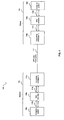
- FIG. 1 shows a block diagram of a 10Gbit/sec Ethernet over twisted-pair cabling (10GBASE-T) link between a master link partner and a slave link partner, in accordance with an embodiment of the invention.
- a system 100 that comprises a master link partner 102 and a slave link partner 104.
- the master link partner 102 and the slave link partner 104 communicate via a 4-wire unshielded twisted pair (UTP) cable 112.
- the master link partner 102 comprises a computer system 106a, a medium access control (MAC) controller 108a, and a transceiver 104a.
- the slave link partner 104 comprises a computer system 106b, a MAC controller 108b, and a transceiver 110b. Notwithstanding, the invention is not limited in this regard.
- the transceiver 110a comprises suitable logic, circuitry, and/or program code that enables communication, for example, transmission and reception of data, between the master link partner 102 and a link partner, such as the slave link partner 104, for example.
- the transceiver 110b comprises suitable logic, circuitry, and/or code that may enable communication between the slave link partner 104 and a link partner, such as the master link partner 102, for example.
- the transceivers 110a and 110b enable 10GBASE-T operations.
- the data transmitted and/or received by the transceivers 110a and 110b is formatted in accordance with the well-known IEEE 802 LAN/MAN standards.
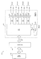
- FIG. 2 shows a block diagram of an exemplary 10GBASE-T link partner, in accordance with an embodiment of the invention.
- a link partner 200 that comprises a transceiver 202, a MAC controller 204, a computer system 206, an interface 208, and a bus controller interface 210.
- the transceiver 202 can be an integrated device that comprises a PHY block 212, a plurality of transmitters 214a, 214c, 214e, and 214g, a plurality of receivers 214b, 214d, 214f, and 214h, a memory 216, and a memory interface 218.
- the transceiver 202 is the same as or substantially similar to the transceivers 110a and 110b described in FIG. 1 .
- the MAC controller 204, the computer system 206, the interface 208, and the bus controller 210 are the same as or substantially similar to the respective MAC controllers 108a and 108b, computer systems 106a and 106b, interfaces 114a and 114b, and bus controller interfaces 116a and 116b described in FIG. 1 .
- the PHY block 212 in the transceiver 202 comprises suitable logic, circuitry, and/or program code that enables operability and/or functionality of PHY layer requirements.
- the PHY block 212 communicates with the MAC controller 204 via the interface 208.
- the interface 208 may be configured to utilize a plurality of serial data lanes for receiving data from the PHY block 212 and/or for transmitting data to the PHY block 212, in order to achieve compatible 10Gb/sec operational speeds.
- the PHY block 212 is configured to operate in one or more of a plurality of communication modes, where each communication mode implements a different communication protocol.
- the transmitters 214a, 214c, 214e, and 214g comprises suitable logic, circuitry, and/or program code that enables transmission of data from the link partner 200 to a link partner via the UTP cable 212 in FIG. 1 , for example.
- the receivers 214b, 214d, 214f, and 214h comprise suitable logic, circuitry, and/or program code that may enable receiving data from a link partner by the link partner 200.
- Each of the four pairs of transmitters and receivers in the transceiver 202 correspond to one of the four wires in the UTP cable 212.
- transceiver 214a and receiver 214b are utilized to communicate with a link partner via the first wire pair in the UTP cable 212.
- transceiver 214g and receiver 214h are utilized to communicate with a link partner via the fourth wire pair in the UTP cable 212.
- each of the four transceiver/receiver pairs correspond to a 2.5 Gbit/sec connection, for example.
- FIG. 3 is a state diagram illustrating modes of operation in a 10GBASE-T link partner, in accordance with an embodiment of the invention.
- a state diagram 300 that comprises an auto-negotiation mode 302, a start-up mode 304, and a data mode 306.
- the PHY block 212 in the transceiver 202 described in FIG. 2 are utilized by a link partner to coordinate state or mode transitions when establishing a network connection with a link partner.
- a master link partner and a slave link partner determines the maximum connection speed that may be supported for communicating with each other.
- the link partners transition to the 10GBASE-T start-up mode 304 where appropriate training signals and/or control information are exchanged in order to establish the 10Gbit/sec network connection.
- the start-up mode 304 certain conditions can arise that require the link partners to transition back to the auto-negotiation mode 302 and determine a new maximum connection speed.
- the link partners When a network or link connection is properly established in the start-up mode 304, the link partners will transition to the data mode 306 where they communicate information. Upon termination of the network connection, the link partners transition back to the auto-negotiation mode 302. In some instances, during the data mode 306, certain conditions can arise that require the link partners to transition to the start-up mode 304 and reestablish the network connection.
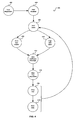
- FIG. 4 is a state diagram illustrating a start-up sequence that includes a PMA training period, in accordance with an embodiment of the invention.
- a state diagram 400 that corresponds to changes in states of operation of the PHY block 212 when a network connection is established.
- a signal is generated to enable the PHY block 212 to transition from a PHY disabled state 404 to a PHY silent state 406.
- the PHY block 212 remains silent, that is, the PHY block 212 does not communicate with the link partner.
- the operation of the PHY block 212 transitions to a PMA train master state 408, if the link partner is configured as a master link partner.
- the operation of the PHY block 212 transitions to a PMA train slave state 410, if the link partner is configured as a slave link partner.
- the master link partner starts sending PMA training frames to the slave link partner.
- the master link partner When the master link partner is ready to receive PMA training frames from the slave link partner, it invites the slave link partner to transmit its own PMA training frames and waits for the slave link partner's PMA training frames.
- the PMA training frames may be long, repetitive or periodic frames that comprise a pseudo random portion or sequence and an information field or InfoField, for example.
- the pseudo random portion may be generated from seed values determined during the auto-negotiation state 402.
- the PMA training frames may be 16k symbols in length and have a duration of approximately 20.48 ⁇ s, for example.
- the PMA training frames are modulated using 2-level pulse amplitude modulation (2-PAM), for example.
- the Info Field portion of the PMA training frames comprises information that enables the Master and Slave link partners to train echo and/or near-end crosstalk cancellers, to train receivers, and to establish appropriate transmitter power levels, for example.
- the contents of the pseudo random portion of PMA training frames shall be known while the contents of the InfoFields vary in accordance with progress in the start-up procedure. Processing of information in response of to received InfoFields need not be performed in real time.
- the slave link partner conditions its receiver section to receive PMA training frames and the InfoFields therein contained from the master link partner. When this is accomplished and an invitation from the master link partner to start transmission is received, the slave link partner starts transmission of PMA training frames.
- the link partners While operating in the PMA master or slave states, the link partners ensure that satisfactory transceiver operation with enough signal-to-noise ratio (SNR) margin is achieved for reliably decoding after completion of the PMA training period physical coding sublayer (PCS) frames.
- This includes requesting through the requested transmit PBO field of InfoFields sent to the link partner that the link partner switches its transmit PBO setting to the requested value.
- the link partners announce to each other when the change of their respective PBO settings will actually occur.
- the PHY block 212 proceeds to the PMA coefficient exchange state 412.
- the link partners send and receive precoding coefficients via InfoFields.
- the operations of the master and slave link partners are symmetrical. For example, 64 decision feedback filter coefficients, 16 coefficients for each of the four wire pairs in the UTP cable, may be communicated to the link partner for later use for precoding, such as Tomlinson-Harashima (TH) precoding, by the link partner during the PMA fine adjustment state 414 and onwards.
- TH Tomlinson-Harashima
- the link partners announce by using the transition count in the InfoFields to each other a transition from PMA coefficient exchange state 412 to the PMA fine adjustment state 414.
- the PMA fine adjustment state 414 ensures proper reception of TH precoded PMA training frames on both sides of the link and final convergence of all adaptive filters.
- the link partners announce by using the transition count in the InfoFields to each other a transition from PMA fine adjust state 414 to the PCS test state 416.
- the completion of the PMA fine adjustment state 414 also corresponds to the completion of the PMA training period.
- the master and slave link partners operations are symmetric. Instead of PMA training frames the link partners send PCS frames using the final coding and modulation for sending data at 10Gbit/sec bi-directionally over the link.
- the PCS frames may be low-density parity-check (LDPC) coded with a mapping of bits to higher-order modulation symbols from a two-dimensional 128-point Double Square (128-DSQ) constellation, and the frames may be 320 ns in duration.
- LDPC low-density parity-check
- a link partner proceeds to the PCS data state 418.
- the link partners send user data from the transmit portion of the MAC interface and deliver user data to the receive portion of the MAC interface. If in the PCS test state 416 or in the PCS data state 418 a link partner detects an error situation, which may consists in too frequent decoding failures, it transitions back to the PHY silent state 406. As a result, the other link partner will also detect an error situation and transition back to the PHY silent state 406.
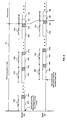
- FIG. 5 depicts an exemplary exchange of PMA training frames between master and slave link partners, in accordance with an embodiment of the invention.
- a PMA training period 501 that may be up to 2 sec in duration, for example.
- the master (M) and slave (S) link partners exchange PMA training frames.
- PMA TRN M frame 500a comprises a pseudo random portion 502a and an InfoField (IF) 504a.
- IF InfoField
- the start of the first PMA TRN M frame 500a corresponds to the start of the PMA training period 501.
- the end of the last PMA TRN M frame 500a corresponds to the end of the PMA training period 501 for the master link partner.
- the master link partner After the end of the PMA training period 501, the master link partner begins PCS operation and transmits PCS frames 506 to the slave link partner during PCS operations in accordance with the state diagram given in FIG. 4 .
- FIG. 5 shows a sequence of slave PMA training (PMA TRN S ) frames 500b transmitted to the master link partner.
- Each PMA TRN S frame 500b comprises a pseudo random portion 502b and an IF 504b.
- the start of the first PMA TRN S frame 500b occurs after the master clock is recovered from the received PMA TRN M frames 500a.
- the end of the last PMA TRN S frame 500b corresponds to the end of the PMA training period 501 for the slave link partner.
- the slave begins PCS operation and transmits PCS frames 508 to the master link partner in accordance with the state diagram given in FIG. 4 .
- FIG. 6 illustrates exemplary InfoField payloads, in accordance with an embodiment of the invention.
- an InfoField (IF) 600 that comprises a delimiter 602, an IF payload 604, and a cyclic redundancy check (CRC) 606.
- the delimiter 602 comprises a known binary sequence.
- the IF 600 may be implemented without a delimiter 602.
- the CRC 606 comprises information for verifying the contents of the IF payload 604, for example.
- the IF payload 604 comprises a plurality of fields that may contain information that may be utilized by the master and slave link partners during the PMA training period of the start-up procedure.
- an IF payload 608 that comprises fields such as control bits 610, current power backoff (PBO) 612, next PBO 614, requested PBO 616, further control bits 618, and transition counter 620.
- the control bits 610 and the further control bits 618 may be utilized to indicate the current state in the start-up procedure and the local receiver's status for reliable decoding.
- the current PBO 612 field may be utilized to indicate the current power backoff of the transmitting link partner from a nominal maximum transmit power level.
- the next PBO 614 field in combination with the transition count may be utilized to announce to the link partner a change in the transmit PBO to the value in the next PBO field.
- the requested PBO 616 field may be utilized to request that the remote link partner sets the transmit PBO to a requested value.
- the transition counter 620 field may be utilized to announce to the remote link partner a transition in the characteristics of the signal of the transmitting link partner.
- the transition counter 620 field may be set to a value that indicates the number of PMA frames after which the transition will occur. The value in this field is decremented with each subsequent transmission of an InfoField 600 until the value zero is reached.
- the link partner need not decode the InfoField of every PMA training frame. It suffices to read the InfoField only occasionally to obtain the current value of the transition count and thus know when an announced change is to occur.
- an IF payload 628 that comprises fields such as control bits 630, index of coefficients sent 632, index of coefficients received 634, further control bits 636, and a group of N coefficient fields containing coefficient 1 638 to coefficient N 640.
- the control bits 630 and the further control bits 636 may indicate the current state in the start-up procedure and the local receiver's status for reliable decoding.
- the index of coefficients sent 632 field may indicate the group of N coefficients currently being transmitted to the link partner in fields coefficient 1 638 to coefficient N 640.
- the index of coefficients received 634 field may acknowledge to the link partner up to which group of N coefficients the transmitting link partner has already correctly received coefficients. In this regard, for example, when the local link partner has received all coefficients from the remote link partner and the remote link partner acknowledges reception of all coefficients, the bidirectional coefficient exchange is complete.
- the link partners may then announce a transition to the PMA fine adjustment state 414.
- the present invention may be realized in hardware, software, or a combination of hardware and software.
- the present invention may be realized in a centralized fashion in at least one programmable computing system, or in a distributed fashion where different elements are spread across several interconnected computing elements. Any kind of computing system or other apparatus adapted for carrying out the methods described herein is suited.
- a typical combination of hardware and software may be a general-purpose computer system with a program for processing captured data and signal traces, and thus carrying out the methods described herein.
- the present invention may also be embedded in a computer program product, which comprises all the features enabling the implementation of the methods described herein, and which when loaded in a computer system is able to carry out these methods.
- Computer program in the present context means any expression, in any language, code or notation, of a set of instructions intended to cause a system having an information processing capability to perform a particular function either directly or after either or both of the following: a) conversion to another language, code or notation; b) reproduction in a different material form.
Landscapes
- Engineering & Computer Science (AREA)
- Computer Networks & Wireless Communication (AREA)
- Signal Processing (AREA)
- Communication Control (AREA)
Description
- This patent application makes reference to, claims priority to, and claims benefit from
United States Provisional Patent Application Serial No. 60/722,677 filed on September 30, 2005 - Certain embodiments of the invention relate to networking. More specifically, certain embodiments of the invention relate to a method and system for training 10Gbit/sec Ethernet transceivers for twisted-pair cabling (10GBASE-T) during a start-up procedure.
- As the number of devices connected to data networks increase and higher data rates are required, there is a growing need for new transmission technologies enabling higher transmission rates over existing copper cabling infrastructures. A current effort to that end is the development of a standard for 10Gbit/sec Ethernet transmission over twisted-pair cabling (10GBASE-T). The emerging 10GBASE-T physical layer (PHY) specification is intended to enable 10Gbit/sec connections over twisted-pair cabling at distances of up to 182 feet for existing cabling, and at distances of up to 330 feet for new cabling, for example. To achieve full-duplex transmission at 10Gbit/sec over four-pair cabling, elaborate digital signal processing techniques are needed to remove or reduce the effects of severe frequency-dependent signal attenuation, signal reflections, near-end and far-end crosstalk between the four pairs, and external signals coupled into the four pairs either from adjacent transmission links or other external noise sources. Moreover, new cabling specifications are developed to diminish susceptibility to external electro-magnetic interferences.
- A pair of 10GBASE-T PHY transceivers on each side of a link must initially be trained during a start-up procedure to adapt transmitter and receiver settings to the specific characteristics of the link. The start-up procedure may include establishing initial synchronization, setting transmit power levels, adjusting echo and near-end crosstalk cancellers, adjusting equalizers, selecting and exchanging precoding coefficients, etc. Elaborate start-up procedures are known in the art, for example those used in voiceband modems. Some start-up procedures are aimed at achieving relatively short start-up times. For lower-rate PHY transceivers prior to 10GBASE-T, real-time execution of start-up specific functions meeting the requirements of time-critical handshake procedures usually did not pose severe problems. For 10GBASE-T, where start-up time may not be a critical issue, minimizing the means required for accomplishing start-up specific functions may be more important. Hence there is a need for a start-up procedure that permits performing such functions by shared hardware, firmware, or software at far less than real-time speed in exchange for a longer start-up time. Then only functions needed for sustained continuous data transmission, such as long digital filters or decoders for error correction decoding, must be realized by highly efficient hardware that can perform these functions in real time.
- Further limitations and disadvantages of conventional and traditional approaches will become apparent to one of skill in the art, through comparison of such systems with some aspects of the present invention as set forth in the remainder of the present application with reference to the drawings.
-
US 2004/090981 describes an initialization method for a network system, which uses a channel estimation to predetermine coefficients of an feed-forward equalizer and an feed-back equalizer. As such, convergence of the feed-forward equalizer, the feed-back equalizer, a timing recovery, an echo canceller and a NEXT canceller is speeded up. Also, interaction of the cited devices and a divergence caused by the interaction are avoided. -
US 2004/091027 describes a system, method and device for negotiating a data transmission mode over a device-to-device interconnection (DDI). A data transceiver circuit is coupled to one or more data lanes of the DDI. A negotiation section receives a link pulse signal on at least one data lane in the DDI during a negotiation period and selectively configures the data transceiver to transmit and receive data on one or more data lanes according to a data transmission mode based upon the received link pulse signal. - In IEEE Computer Society: "802.3ae: IEEE Standard for Information technology - Telecommunications and information exchange between systems - Local and metropolitan area networks - Specific requirements, Part 3: Carrier Sense Multiple Access with Collision Detection (CSMA/CD) Access Method and Physical Layer Specifications", IEEE STD 802.3ae-2002, 30 August 2002, there are described Carrier Sense Multiple Access with Collision Detection (CSMA/CD) access method and physical layer specifications and Media Access Control (MAC) parameters, physical layers and management parameters for 10Gb/s operation.
- According to the invention, there are provided a method for setting up communication devices as defined by
independent claim 1, and a system for setting up communication devices as defined by independent claim 7. - Further advantageous features of the invention are defined by the dependent subclaims.
- A system and/or method is provided for 10Gbit/sec Ethernet over twisted-pair cabling (10GBASE-T) start-up, substantially as shown and/or described in connection with at least one of the figures, as set forth more completely in the claims.
- According to an aspect of the invention, a method for setting up communication devices is provided, the method comprising:
- exchanging physical medium attachment (PMA) training frames periodically between link partners during a training period, wherein a majority portion of each of said PMA training frames is comprised of pseudo random known sequences which are used for establishing transceiver operations for communication between said link partners, and wherein said link partners are communicatively coupled via a wired Ethernet link.
- Advantageously, each of said periodically transmitted PMA training frames comprises another portion for exchanging parameters and control information.
- Advantageously, said another portion for exchanging parameters and control information comprises fields for sending a plurality of coefficients and associated index fields indicating which coefficients are currently being transmitted and which coefficients have already been received.
- Advantageously, said another portion for exchanging parameters and control information comprises one or more of a current power backoff (PBO) field, a next PBO field, a requested PBO field, a transition count field, and at least one control field.
- Advantageously, the method further comprises determining a power level change based on said current PBO field, said next PBO field, and said requested PBO field.
- Advantageously, said transition count field indicates a number of said periodically transmitted PMA training frames after which a power level change occurs in a signal of a transmitting link partner.
- Advantageously, said transition count field indicates a number of said periodically transmitted PMA training frames after which a state transition occurs in a transmitting link partner.
- Advantageously, the method further comprises transmitting PMA training frames periodically from a master link partner to a slave link partner from a start of said training period.
- Advantageously, the method further comprises transmitting PMA training frames periodically from a slave link partner to a master link partner after said slave link partner recovers a master clock during said training period.
- Advantageously, the method further comprises programming coefficients in a precoder in each of said link partners during said training period for said communication between said link partners.
- Advantageously, said precoder is a Tomlinson-Harashima (TH) precoder.
- According to an aspect of the invention, a system for setting up communication devices is provided, the system comprising:
- a transceiver that enables exchanging physical medium attachment (PMA) training frames periodically between link partners during a training period, wherein a majority portion of each of said PMA training frames is comprised of pseudo random known sequences which are used for establishing transceiver operations for communication between said link partners, and wherein said link partners are communicatively coupled via a wired Ethernet link.
- Advantageously, each of said periodically transmitted PMA training frames comprises another portion for exchanging parameters and control information.
- Advantageously, said another portion for exchanging parameters and control information comprises fields for sending a plurality of coefficients and associated index fields indicating which coefficients are currently being transmitted and which coefficients have already been received.
- Advantageously, said another portion for exchanging parameters and control information comprises one or more of a current power backoff (PBO) field, a next PBO field, a requested PBO field, a transition count field, and at least one control field.
- Advantageously, said transceiver enables determining a power level change based on said current PBO field, said next PBO field, and said requested PBO field.
- Advantageously, said transition count field indicates a number of said periodically transmitted PMA training frames after which a power level change occurs in a signal of a transmitting link partner.
- Advantageously, said transition count field indicates a number of said periodically transmitted PMA training frames after which a state transition occurs in a transmitting link partner.
- Advantageously, the system further comprises transmitting PMA training frames periodically from a master link partner to a slave link partner from a start of said training period.
- Advantageously, said transceiver enables transmitting PMA training frames periodically from a slave link partner to a master link partner after said slave link partner recovers a master clock during said training period.
- Advantageously, said transceiver enables programming coefficients in a precoder in each of said link partners during said training period for said communication between said link partners.
- Advantageously, said precoder is a Tomlinson-Harashima (TH) precoder.
- These and other advantages, aspects and novel features of the present invention, as well as details of an illustrated embodiment thereof, will be more fully understood from the following description and drawings.
-
FIG. 1 shows a block diagram of a 10Gbit/sec Ethernet over twisted-pair cabling (10GBASE-T) link between a master link partner and a slave link partner, in accordance with an embodiment of the invention. -
FIG. 2 shows a block diagram of an exemplary 10GBASE-T link partner, in accordance with an embodiment of the invention. -
FIG. 3 is a state diagram illustrating modes of operation in a 10GBASE-T link partner, in accordance with an embodiment of the invention. -
FIG. 4 is a state diagram illustrating a start-up sequence that includes a physical medium attachment (PMA) training period, in accordance with an embodiment of the invention. -
FIG. 5 depicts an exemplary exchange of PMA training frames between master and slave link partners, in accordance with an embodiment of the invention. -
FIG. 6 illustrates exemplary InfoField payloads, in accordance with an embodiment of the invention. - Certain embodiments of the invention may be found in the start-up procedure of the emerging physical layer specification 10BASE-T, which is intended to become part of the IEEE 802.3 Ethernet standard. 10GBASE-T transceivers will enable 10 Gbit/sec transmission over twisted-pair copper cables. The specification provides for full-duplex transmission simultaneously over four pairs of ISO Class E or Class F cables at a rate of 2.5 Gbit/sec per pair.
- During IEEE 802.3 Auto Negotiation, the link partners agree on the type of physical layer transmission to be used. Also, one transceiver assumes the role of a Master and the other the role of a Slave. If 10GBASE-T has been selected, the link partners then proceed to the 10GBASE-T start-up procedure.
- The 10GBASE-T start-up procedure is characterized by the following features. During an initial PMA (Physical Medium Attachment) training period, long PMA training frames are periodically transmitted over all four pairs. The length of the PMA training frames may be 16k symbol times, for example. Each PMA training frame consists of a known pseudo random sequence of binary modulation symbols. In addition, the frames transmitted over one of the four pairs in each direction comprise an InfoField, which is short compared to the length of the PMA training frames. The InfoFields are used for exchanging parameters and control information between the link partners. Transmission is started by the Master transceiver on all four pairs. After detecting the Master signals and receiving an invitation to start transmission, the Slave transceiver also starts to transmit on all four pairs.
- Knowledge of the periodically transmitted binary sequences enables the receiver sections of the link partners to acquire and maintain symbol timing and PMA frame synchronization throughout the entire PMA training period. For other purposes the known long sequences exhibit the characteristics of essentially random sequences.
- The InfoFields convey control information of various types. For example, the InfoField's payload comprises fields for indicating current transmit PBO (power backoff) of the transmitting transceiver, next transmit PBO of the transmitting transceiver, requested PBO for the transceiver of the link partner, and a transition count. The InfoField's payload contains also fields for sending precoder coefficients, indicating the SNR margin in the receiver section of a transceiver, and other control information. The transition count indicates the remaining number of PMA training frames, after which an announced change will occur. The change may be a change in transmit PBO and/or or a transition to a next state in the state diagram of the transmitting transceiver. A link partner is not required to decode every received InfoField, and is never required to react immediately to information received in InfoFields. For example, by only occasionally decoding an InfoField and reading the transition count therein, a link partner can determine when the announced change is to occur. Thus resources needed for performing a variety of start-up specific functions can be allocated in transceivers with great flexibility and without stringent real-time requirements.
-
FIG. 1 shows a block diagram of a 10Gbit/sec Ethernet over twisted-pair cabling (10GBASE-T) link between a master link partner and a slave link partner, in accordance with an embodiment of the invention. Referring toFIG. 1 , there is shown asystem 100 that comprises amaster link partner 102 and aslave link partner 104. Themaster link partner 102 and theslave link partner 104 communicate via a 4-wire unshielded twisted pair (UTP)cable 112. Themaster link partner 102 comprises acomputer system 106a, a medium access control (MAC)controller 108a, and a transceiver 104a. Theslave link partner 104 comprises acomputer system 106b, aMAC controller 108b, and atransceiver 110b. Notwithstanding, the invention is not limited in this regard. - The
transceiver 110a comprises suitable logic, circuitry, and/or program code that enables communication, for example, transmission and reception of data, between themaster link partner 102 and a link partner, such as theslave link partner 104, for example. Similarly, thetransceiver 110b comprises suitable logic, circuitry, and/or code that may enable communication between theslave link partner 104 and a link partner, such as themaster link partner 102, for example. Thetransceivers transceivers -
FIG. 2 shows a block diagram of an exemplary 10GBASE-T link partner, in accordance with an embodiment of the invention. Referring toFIG. 2 , there is shown alink partner 200 that comprises atransceiver 202, aMAC controller 204, acomputer system 206, aninterface 208, and abus controller interface 210. Thetransceiver 202 can be an integrated device that comprises aPHY block 212, a plurality oftransmitters receivers memory 216, and amemory interface 218. Thetransceiver 202 is the same as or substantially similar to thetransceivers FIG. 1 . Similarly, theMAC controller 204, thecomputer system 206, theinterface 208, and thebus controller 210 are the same as or substantially similar to therespective MAC controllers computer systems interfaces bus controller interfaces FIG. 1 . - The
PHY block 212 in thetransceiver 202 comprises suitable logic, circuitry, and/or program code that enables operability and/or functionality of PHY layer requirements. ThePHY block 212 communicates with theMAC controller 204 via theinterface 208. In one aspect of the invention, theinterface 208 may be configured to utilize a plurality of serial data lanes for receiving data from thePHY block 212 and/or for transmitting data to thePHY block 212, in order to achieve compatible 10Gb/sec operational speeds. ThePHY block 212 is configured to operate in one or more of a plurality of communication modes, where each communication mode implements a different communication protocol. - The
transmitters link partner 200 to a link partner via theUTP cable 212 inFIG. 1 , for example. Thereceivers link partner 200. Each of the four pairs of transmitters and receivers in thetransceiver 202 correspond to one of the four wires in theUTP cable 212. For example,transceiver 214a andreceiver 214b are utilized to communicate with a link partner via the first wire pair in theUTP cable 212. Similarly,transceiver 214g andreceiver 214h are utilized to communicate with a link partner via the fourth wire pair in theUTP cable 212. In this regard, each of the four transceiver/receiver pairs correspond to a 2.5 Gbit/sec connection, for example. -
FIG. 3 is a state diagram illustrating modes of operation in a 10GBASE-T link partner, in accordance with an embodiment of the invention. Referring toFIG. 3 , there is shown a state diagram 300 that comprises an auto-negotiation mode 302, a start-upmode 304, and adata mode 306. ThePHY block 212 in thetransceiver 202 described inFIG. 2 are utilized by a link partner to coordinate state or mode transitions when establishing a network connection with a link partner. During the auto-negotiation mode 302, a master link partner and a slave link partner determines the maximum connection speed that may be supported for communicating with each other. - When the auto-
negotiation mode 302 is completed and 10GBASE-T has been selected as a physical layer transmission method, the link partners transition to the 10GBASE-T start-upmode 304 where appropriate training signals and/or control information are exchanged in order to establish the 10Gbit/sec network connection. In some instances, during the start-upmode 304, certain conditions can arise that require the link partners to transition back to the auto-negotiation mode 302 and determine a new maximum connection speed. - When a network or link connection is properly established in the start-up
mode 304, the link partners will transition to thedata mode 306 where they communicate information. Upon termination of the network connection, the link partners transition back to the auto-negotiation mode 302. In some instances, during thedata mode 306, certain conditions can arise that require the link partners to transition to the start-upmode 304 and reestablish the network connection. -
FIG. 4 is a state diagram illustrating a start-up sequence that includes a PMA training period, in accordance with an embodiment of the invention. Referring toFIG. 4 , there is shown a state diagram 400 that corresponds to changes in states of operation of thePHY block 212 when a network connection is established. When the auto-negotiation state 402 is completed, a signal is generated to enable thePHY block 212 to transition from a PHYdisabled state 404 to a PHYsilent state 406. During the PHYsilent state 406, the PHY block 212 remains silent, that is, thePHY block 212 does not communicate with the link partner. After the appropriate silence interval is completed, the operation of the PHY block 212 transitions to a PMAtrain master state 408, if the link partner is configured as a master link partner. Alternatively, the operation of the PHY block 212 transitions to a PMAtrain slave state 410, if the link partner is configured as a slave link partner. - During the PMA
train master state 408, the master link partner starts sending PMA training frames to the slave link partner. When the master link partner is ready to receive PMA training frames from the slave link partner, it invites the slave link partner to transmit its own PMA training frames and waits for the slave link partner's PMA training frames. - The PMA training frames may be long, repetitive or periodic frames that comprise a pseudo random portion or sequence and an information field or InfoField, for example. The pseudo random portion may be generated from seed values determined during the auto-
negotiation state 402. The PMA training frames may be 16k symbols in length and have a duration of approximately 20.48 µs, for example. The PMA training frames are modulated using 2-level pulse amplitude modulation (2-PAM), for example. The Info Field portion of the PMA training frames comprises information that enables the Master and Slave link partners to train echo and/or near-end crosstalk cancellers, to train receivers, and to establish appropriate transmitter power levels, for example. The contents of the pseudo random portion of PMA training frames shall be known while the contents of the InfoFields vary in accordance with progress in the start-up procedure. Processing of information in response of to received InfoFields need not be performed in real time. - During the PMA
train slave state 410, the slave link partner conditions its receiver section to receive PMA training frames and the InfoFields therein contained from the master link partner. When this is accomplished and an invitation from the master link partner to start transmission is received, the slave link partner starts transmission of PMA training frames. - While operating in the PMA master or slave states, the link partners ensure that satisfactory transceiver operation with enough signal-to-noise ratio (SNR) margin is achieved for reliably decoding after completion of the PMA training period physical coding sublayer (PCS) frames. This includes requesting through the requested transmit PBO field of InfoFields sent to the link partner that the link partner switches its transmit PBO setting to the requested value. By using the transition count field in the InfoFields, the link partners announce to each other when the change of their respective PBO settings will actually occur.
- After completion of either the PMA
train master state 408 or the PMAtrain slave state 410, the PHY block 212 proceeds to the PMAcoefficient exchange state 412. During the PMAcoefficient exchange state 412, the link partners send and receive precoding coefficients via InfoFields. In this regard, the operations of the master and slave link partners are symmetrical. For example, 64 decision feedback filter coefficients, 16 coefficients for each of the four wire pairs in the UTP cable, may be communicated to the link partner for later use for precoding, such as Tomlinson-Harashima (TH) precoding, by the link partner during the PMAfine adjustment state 414 and onwards. After the exchange of coefficients is completed, the link partners announce by using the transition count in the InfoFields to each other a transition from PMAcoefficient exchange state 412 to the PMAfine adjustment state 414. - During the PMA
fine adjustment state 414 the coefficients received from the link partner are employed for sending additional PMA training frames now with TH precoding. After the link partners have to completed and refined adjustments necessary to establish the final link connection. In this regard, the PMAfine adjustment state 414 ensures proper reception of TH precoded PMA training frames on both sides of the link and final convergence of all adaptive filters. When this is accomplished, the link partners announce by using the transition count in the InfoFields to each other a transition from PMA fine adjuststate 414 to thePCS test state 416. The completion of the PMAfine adjustment state 414 also corresponds to the completion of the PMA training period. - During the
PCS test state 416, the master and slave link partners operations are symmetric. Instead of PMA training frames the link partners send PCS frames using the final coding and modulation for sending data at 10Gbit/sec bi-directionally over the link. For example, the PCS frames may be low-density parity-check (LDPC) coded with a mapping of bits to higher-order modulation symbols from a two-dimensional 128-point Double Square (128-DSQ) constellation, and the frames may be 320 ns in duration. In thePCS test state 416, only scrambled test data are transmitted, which can be distinguished from user data. Each link partner monitors its receiver performance. If after the determined time period satisfactory receiver performance is asserted, a link partner proceeds to thePCS data state 418. In this state, the link partners send user data from the transmit portion of the MAC interface and deliver user data to the receive portion of the MAC interface. If in thePCS test state 416 or in the PCS data state 418 a link partner detects an error situation, which may consists in too frequent decoding failures, it transitions back to the PHYsilent state 406. As a result, the other link partner will also detect an error situation and transition back to the PHYsilent state 406. -
FIG. 5 depicts an exemplary exchange of PMA training frames between master and slave link partners, in accordance with an embodiment of the invention. Referring toFIG. 5 , there is shown aPMA training period 501 that may be up to 2 sec in duration, for example. During thePMA training period 501, the master (M) and slave (S) link partners exchange PMA training frames. Regarding the master link partner, there is shown a sequence of master PMA training (PMA TRNM)frames 500a transmitted to the slave link partner. Each PMA TRNM frame 500a comprises a pseudorandom portion 502a and an InfoField (IF) 504a. The start of the first PMA TRNM frame 500a corresponds to the start of thePMA training period 501. The end of the last PMA TRNM frame 500a corresponds to the end of thePMA training period 501 for the master link partner. After the end of thePMA training period 501, the master link partner begins PCS operation and transmits PCS frames 506 to the slave link partner during PCS operations in accordance with the state diagram given inFIG. 4 . - Similarly,
FIG. 5 shows a sequence of slave PMA training (PMA TRNS) frames 500b transmitted to the master link partner. Each PMA TRNS frame 500b comprises a pseudorandom portion 502b and anIF 504b. The start of the first PMA TRNS frame 500b occurs after the master clock is recovered from the received PMA TRNM frames 500a. The end of the last PMA TRNS frame 500b corresponds to the end of thePMA training period 501 for the slave link partner. After the end of thePMA training period 501, the slave begins PCS operation and transmits PCS frames 508 to the master link partner in accordance with the state diagram given inFIG. 4 . -
FIG. 6 illustrates exemplary InfoField payloads, in accordance with an embodiment of the invention. Referring toFIG. 6 , there is shown an InfoField (IF) 600 that comprises adelimiter 602, an IFpayload 604, and a cyclic redundancy check (CRC) 606. Thedelimiter 602 comprises a known binary sequence. In some instances, theIF 600 may be implemented without adelimiter 602. TheCRC 606 comprises information for verifying the contents of theIF payload 604, for example. - The IF
payload 604 comprises a plurality of fields that may contain information that may be utilized by the master and slave link partners during the PMA training period of the start-up procedure. In this regard, there may be various configurations of fields in theIF payload 604 based on the current state in the start-up procedure. For example, there is shown inFIG. 6 an IFpayload 608 that comprises fields such ascontrol bits 610, current power backoff (PBO) 612,next PBO 614, requestedPBO 616,further control bits 618, andtransition counter 620. Thecontrol bits 610 and thefurther control bits 618 may be utilized to indicate the current state in the start-up procedure and the local receiver's status for reliable decoding. Thecurrent PBO 612 field may be utilized to indicate the current power backoff of the transmitting link partner from a nominal maximum transmit power level. Thenext PBO 614 field in combination with the transition count may be utilized to announce to the link partner a change in the transmit PBO to the value in the next PBO field. The requestedPBO 616 field may be utilized to request that the remote link partner sets the transmit PBO to a requested value. - The
transition counter 620 field may be utilized to announce to the remote link partner a transition in the characteristics of the signal of the transmitting link partner. Thetransition counter 620 field may be set to a value that indicates the number of PMA frames after which the transition will occur. The value in this field is decremented with each subsequent transmission of anInfoField 600 until the value zero is reached. In this regard, the link partner need not decode the InfoField of every PMA training frame. It suffices to read the InfoField only occasionally to obtain the current value of the transition count and thus know when an announced change is to occur. - Also shown in
FIG. 6 is an IFpayload 628 that comprises fields such ascontrol bits 630, index of coefficients sent 632, index of coefficients received 634,further control bits 636, and a group of N coefficient fields containing coefficient 1 638 to coefficientN 640. Thecontrol bits 630 and thefurther control bits 636 may indicate the current state in the start-up procedure and the local receiver's status for reliable decoding. The index of coefficients sent 632 field may indicate the group of N coefficients currently being transmitted to the link partner in fields coefficient 1 638 to coefficientN 640. The index of coefficients received 634 field may acknowledge to the link partner up to which group of N coefficients the transmitting link partner has already correctly received coefficients. In this regard, for example, when the local link partner has received all coefficients from the remote link partner and the remote link partner acknowledges reception of all coefficients, the bidirectional coefficient exchange is complete. The link partners may then announce a transition to the PMAfine adjustment state 414. - The approach described herein permits realizations of start-up specific function with great flexibility in non-real time.
- Accordingly, the present invention may be realized in hardware, software, or a combination of hardware and software. The present invention may be realized in a centralized fashion in at least one programmable computing system, or in a distributed fashion where different elements are spread across several interconnected computing elements. Any kind of computing system or other apparatus adapted for carrying out the methods described herein is suited. A typical combination of hardware and software may be a general-purpose computer system with a program for processing captured data and signal traces, and thus carrying out the methods described herein.
- The present invention may also be embedded in a computer program product, which comprises all the features enabling the implementation of the methods described herein, and which when loaded in a computer system is able to carry out these methods. Computer program in the present context means any expression, in any language, code or notation, of a set of instructions intended to cause a system having an information processing capability to perform a particular function either directly or after either or both of the following: a) conversion to another language, code or notation; b) reproduction in a different material form.
- While the present invention has been described with reference to certain embodiments, it will be understood by those skilled in the art that various changes may be made and equivalents may be substituted without departing from the scope of the present invention. In addition, many modifications may be made to adapt a particular situation or material to the teachings of the present invention without departing from its scope. Therefore, it is intended that the present invention not be limited to the particular embodiment disclosed, but that the present invention will include all embodiments falling within the scope of the appended claims.
Claims (10)
- A method for setting up communication devices, the method comprising:exchanging physical medium attachment, PMA, training frames periodically between link partners during a training period, wherein a majority portion of each of said PMA training frames is comprised of pseudo random known sequences which are used for establishing transceiver operations for communication between said link partners, and wherein said link partners are communicatively coupled via a wired Ethernet link.
- The method according to claim 1, wherein each of said periodically transmitted PMA training frames comprises another portion for exchanging parameters and control information.
- The method according to claim 2, wherein said another portion for exchanging parameters and control information comprises fields for sending a plurality of coefficients and associated index fields indicating which coefficients are currently being transmitted and which coefficients have already been received.
- The method according to claim 2, wherein said another portion for exchanging parameters and control information comprises one or more of a current power backoff, PBO, field, a next PBO field, a requested PBO field, a transition count field, and at least one control field.
- The method according to claim 4, further comprising determining a power level change based on said current PBO field, said next PBO field, and said requested PBO field.
- The method according to claim 4, wherein said transition count field indicates a number of said periodically transmitted PMA training frames after which a power level change occurs in a signal of a transmitting link partner.
- A system for setting up communication devices, the system comprising:a transceiver that enables exchanging physical medium attachment, PMA, training frames periodically between link partners during a training period, wherein a majority portion of each of said PMA training frames is comprised of pseudo random known sequences which are used for establishing transceiver operations for communication between said link partners, and wherein said link partners are communicatively coupled via a wired Ethernet link.
- The system according to claim 7, wherein each of said periodically transmitted PMA training frames comprises another portion for exchanging parameters and control information.
- The system according to claim 8, wherein said another portion for exchanging parameters and control information comprises fields for sending a plurality of coefficients and associated index fields indicating which coefficients are currently being transmitted and which coefficients have already been received.
- The system according to claim 8, wherein said another portion for exchanging parameters and control information comprises one or more of a current power backoff, PBO, field, a next PBO field, a requested PBO field, a transition count field, and at least one control field.
Applications Claiming Priority (2)
| Application Number | Priority Date | Filing Date | Title |
|---|---|---|---|
| US72267705P | 2005-09-30 | 2005-09-30 | |
| US11/410,172 US7936778B2 (en) | 2005-09-30 | 2006-04-24 | Method and system for 10GBASE-T start-up |
Publications (2)
| Publication Number | Publication Date |
|---|---|
| EP1770912A1 EP1770912A1 (en) | 2007-04-04 |
| EP1770912B1 true EP1770912B1 (en) | 2008-11-05 |
Family
ID=37116181
Family Applications (1)
| Application Number | Title | Priority Date | Filing Date |
|---|---|---|---|
| EP06012741A Active EP1770912B1 (en) | 2005-09-30 | 2006-06-21 | Method and system for 10BASE-T start-up |
Country Status (5)
| Country | Link |
|---|---|
| US (3) | US7936778B2 (en) |
| EP (1) | EP1770912B1 (en) |
| CN (1) | CN1941649B (en) |
| DE (1) | DE602006003500D1 (en) |
| TW (1) | TWI377809B (en) |
Families Citing this family (45)
| Publication number | Priority date | Publication date | Assignee | Title |
|---|---|---|---|---|
| US7936778B2 (en) | 2005-09-30 | 2011-05-03 | Broadcom Corporation | Method and system for 10GBASE-T start-up |
| US20070192505A1 (en) * | 2006-02-13 | 2007-08-16 | Teranetics, Inc. | Auto-sequencing transmission speed of a data port |
| US7860020B2 (en) | 2006-05-22 | 2010-12-28 | Plx Technology, Inc. | Master/slave transceiver power back-off |
| US20080219289A1 (en) * | 2006-11-15 | 2008-09-11 | William Lee Harrison | 10GBase-T link speed arbitration for 30m transceivers |
| US8565337B2 (en) * | 2007-02-07 | 2013-10-22 | Valens Semiconductor Ltd. | Devices for transmitting digital video and data over the same wires |
| US7835289B2 (en) * | 2007-02-07 | 2010-11-16 | Valens Semiconductor Ltd. | Methods for managing a multi data type communication link |
| US9426006B2 (en) * | 2007-02-07 | 2016-08-23 | Valens Semiconductor Ltd. | Low power partial functionality communication link |
| US7835382B2 (en) * | 2007-02-07 | 2010-11-16 | Valens Semiconductor Ltd. | High definition and low power partial functionality communication link |
| US20090097401A1 (en) * | 2007-10-12 | 2009-04-16 | Wael William Diab | Method and system for configurable data rate thresholds for energy efficient ethernet |
| TWI441464B (en) * | 2008-10-17 | 2014-06-11 | Realtek Semiconductor Corp | Network communication device for increasing linking quality and method thereof |
| TWI469595B (en) * | 2008-11-27 | 2015-01-11 | Realtek Semiconductor Corp | Remote control method for a physical layer and related physical layer device |
| US8516331B2 (en) | 2010-01-29 | 2013-08-20 | Broadcom Corporation | Systems for high-speed backplane applications using FEC encoding |
| US8385346B2 (en) * | 2010-04-08 | 2013-02-26 | Broadcom Corporation | System and method for forming N0GBASE-T |
| US8503474B2 (en) * | 2010-06-13 | 2013-08-06 | Broadcom Corporation | System and method for enhanced physical layer device interface capability for backward support of fast retrain |
| US9160482B2 (en) * | 2010-09-13 | 2015-10-13 | Broadcom Corporation | PHY retraining |
| US8732262B2 (en) | 2011-08-30 | 2014-05-20 | Adc Dsl Systems, Inc. | Rate adaptive auto-negotiation |
| US8804798B2 (en) | 2011-09-16 | 2014-08-12 | Aquantia Corporation | Transceiver spectrum control for cross-talk mitigation |
| EP2840861B1 (en) * | 2012-04-16 | 2020-11-04 | ZTE Corporation | Peer-to-peer wireless communication-based transmission method and device |
| CN103378927B (en) * | 2012-04-20 | 2019-01-11 | 中兴通讯股份有限公司 | Data transmission method for uplink and device |
| US9252968B2 (en) * | 2012-06-22 | 2016-02-02 | Intel Corporation | Link training and training frame for 100GBPS ethernet |
| CN103716075B (en) * | 2012-09-29 | 2016-12-21 | 华为技术有限公司 | The method and apparatus of joint channel correction between a kind of multiple Remote Radio Unit |
| US9112722B2 (en) * | 2012-11-29 | 2015-08-18 | Intel Corporation | PMA-size training frame for 100GBASE-KP4 |
| US9344146B2 (en) * | 2013-03-11 | 2016-05-17 | Intel Corporation | De-correlating training pattern sequences between lanes in high-speed multi-lane links and interconnects |
| US10148508B1 (en) * | 2013-08-14 | 2018-12-04 | Aquantia Corp. | Method and system for ethernet transceiver rate control |
| US9509438B2 (en) * | 2013-09-30 | 2016-11-29 | Intel Corporation | Determining a high data rate for backchannel communications for initialization of high-speed networks |
| CN105659669B (en) * | 2013-11-08 | 2019-07-26 | 英特尔Ip公司 | Poewr control method and system for wireless network |
| US9628220B2 (en) * | 2014-04-15 | 2017-04-18 | Broadcom Corporation | Remote TX training with a re-timer |
| US9742465B1 (en) | 2014-12-05 | 2017-08-22 | Aquantia Corp. | NBASE-T PHY-to-PHY information exchange method and apparatus |
| US10069521B1 (en) | 2015-01-29 | 2018-09-04 | Aquantia Corp. | Intelligent power balancing for NBASE-T ethernet |
| WO2018161273A1 (en) * | 2017-03-08 | 2018-09-13 | Credo Technology Group Ltd. | Ethernet link extension method and device |
| US10530906B2 (en) * | 2017-07-13 | 2020-01-07 | Avago Technologies International Sales Pte. Limited | High-speed interconnect solutions with support for continuous time back channel communication |
| KR102371823B1 (en) * | 2017-12-04 | 2022-03-07 | 주식회사 엘엑스세미콘 | Method for transmitting and receiving data in display device and display panel driving apparatus |
| US10771100B1 (en) | 2019-03-22 | 2020-09-08 | Marvell Asia Pte., Ltd. | Method and apparatus for efficient fast retraining of ethernet transceivers |
| US11228465B1 (en) * | 2019-03-22 | 2022-01-18 | Marvell Asia Pte, Ltd. | Rapid training method for high-speed ethernet |
| US11115151B1 (en) | 2019-03-22 | 2021-09-07 | Marvell Asia Pte, Ltd. | Method and apparatus for fast retraining of ethernet transceivers based on trickling error |
| US10985801B1 (en) * | 2019-08-28 | 2021-04-20 | Marvell Asia Pte., Ltd. | Ethernet link transmit power method based on on-chip detected alien crosstalk feedback |
| US10944584B1 (en) | 2019-10-11 | 2021-03-09 | Credo Technology Group Limited | Single-ended signaling between differential ethernet interfaces |
| US11038602B1 (en) | 2020-02-05 | 2021-06-15 | Credo Technology Group Limited | On-chip jitter evaluation for SerDes |
| CN113346925B (en) * | 2020-03-01 | 2022-11-18 | 默升科技集团有限公司 | Active Ethernet cable and manufacturing method thereof |
| US10892763B1 (en) | 2020-05-14 | 2021-01-12 | Credo Technology Group Limited | Second-order clock recovery using three feedback paths |
| EP4138351A4 (en) | 2020-05-15 | 2023-05-24 | Huawei Technologies Co., Ltd. | Method for isolating narrowband interference and communication apparatus |
| US11695490B2 (en) * | 2020-09-25 | 2023-07-04 | Marvell Asia Pte Ltd | Robust link synchronization in ethernet networks |
| US11424968B1 (en) | 2021-06-10 | 2022-08-23 | Credo Technology Group Limited | Retimer training during link speed negotiation and link training |
| US12375110B1 (en) * | 2021-09-29 | 2025-07-29 | Marvell Asia Pte Ltd | Ethernet physical layer transceiver with graceful temperature protection |
| US20240235906A1 (en) * | 2022-12-19 | 2024-07-11 | Intel Corporation | Precoding during link establishment |
Family Cites Families (11)
| Publication number | Priority date | Publication date | Assignee | Title |
|---|---|---|---|---|
| US5907553A (en) * | 1997-04-08 | 1999-05-25 | Level One Communications, Inc. | Power savings in multiple technology physical layer devices supporting autonegotiation |
| US6751254B1 (en) * | 1999-05-05 | 2004-06-15 | Panasonic Communications Co., Ltd. | Activation of multiple xDSL modems with power control measurement |
| US7068609B2 (en) * | 2000-08-09 | 2006-06-27 | Broadcom Corporation | Method and apparatus for performing wire speed auto-negotiation |
| US6983047B1 (en) * | 2000-08-29 | 2006-01-03 | Lucent Technologies Inc. | Echo canceling system for a bit pump and method of operating the same |
| US6961373B2 (en) * | 2002-07-01 | 2005-11-01 | Solarflare Communications, Inc. | Method and apparatus for channel equalization |
| US20040091027A1 (en) | 2002-11-07 | 2004-05-13 | Booth Bradley J. | System, method and device for autonegotiation |
| TWI222794B (en) * | 2002-11-07 | 2004-10-21 | Realtek Semiconductor Corp | Initialization method for network system |
| GB2400770B (en) * | 2003-04-17 | 2006-03-22 | Agilent Technologies Inc | Testing network communications |
| EP1605655A3 (en) * | 2004-06-07 | 2008-02-27 | Broadcom Corporation | Upstream power cutback |
| US7366931B2 (en) * | 2004-12-30 | 2008-04-29 | Intel Corporation | Memory modules that receive clock information and are placed in a low power state |
| US7936778B2 (en) | 2005-09-30 | 2011-05-03 | Broadcom Corporation | Method and system for 10GBASE-T start-up |
-
2006
- 2006-04-24 US US11/410,172 patent/US7936778B2/en active Active
- 2006-06-21 DE DE602006003500T patent/DE602006003500D1/en active Active
- 2006-06-21 EP EP06012741A patent/EP1770912B1/en active Active
- 2006-08-10 CN CN2006101110358A patent/CN1941649B/en not_active Expired - Fee Related
- 2006-09-29 TW TW095136247A patent/TWI377809B/en active
-
2011
- 2011-05-03 US US13/099,760 patent/US8437366B2/en active Active
-
2013
- 2013-05-06 US US13/887,612 patent/US8654786B2/en active Active
Also Published As
| Publication number | Publication date |
|---|---|
| CN1941649A (en) | 2007-04-04 |
| US20130243011A1 (en) | 2013-09-19 |
| CN1941649B (en) | 2012-03-28 |
| TW200729833A (en) | 2007-08-01 |
| US8654786B2 (en) | 2014-02-18 |
| EP1770912A1 (en) | 2007-04-04 |
| US20070076722A1 (en) | 2007-04-05 |
| US8437366B2 (en) | 2013-05-07 |
| US20110205934A1 (en) | 2011-08-25 |
| DE602006003500D1 (en) | 2008-12-18 |
| TWI377809B (en) | 2012-11-21 |
| US7936778B2 (en) | 2011-05-03 |
Similar Documents
| Publication | Publication Date | Title |
|---|---|---|
| EP1770912B1 (en) | Method and system for 10BASE-T start-up | |
| EP1912383B1 (en) | Method and system for an extended range ethernet link discovery signaling | |
| EP1903733B1 (en) | Method and system for an extended range ethernet line code | |
| US9699000B2 (en) | Method and system for utilizing a 10/100/1G/10G base-T PHY device for single channel and shared channel networks | |
| US9258103B2 (en) | Method and system for monitoring activity of a remote link partner to trigger training of ethernet channels to support EEE networks | |
| US7068609B2 (en) | Method and apparatus for performing wire speed auto-negotiation | |
| US8228795B2 (en) | Method and system for extended reach copper transceiver | |
| US8320411B1 (en) | Fast retraining for transceivers in communication systems | |
| US9807208B2 (en) | Adaptive rate control of NBASE-T data transport system | |
| US20080225879A1 (en) | Method and system for reducing transceiver power via a variable symbol rate | |
| HK1119503B (en) | Method and system for wire communication |
Legal Events
| Date | Code | Title | Description |
|---|---|---|---|
| PUAI | Public reference made under article 153(3) epc to a published international application that has entered the european phase |
Free format text: ORIGINAL CODE: 0009012 |
|
| AK | Designated contracting states |
Kind code of ref document: A1 Designated state(s): AT BE BG CH CY CZ DE DK EE ES FI FR GB GR HU IE IS IT LI LT LU LV MC NL PL PT RO SE SI SK TR |
|
| AX | Request for extension of the european patent |
Extension state: AL BA HR MK YU |
|
| RAP1 | Party data changed (applicant data changed or rights of an application transferred) |
Owner name: BROADCOM CORPORATION |
|
| 17P | Request for examination filed |
Effective date: 20071004 |
|
| 17Q | First examination report despatched |
Effective date: 20071102 |
|
| AKX | Designation fees paid |
Designated state(s): DE FR GB |
|
| R17C | First examination report despatched (corrected) |
Effective date: 20071221 |
|
| GRAP | Despatch of communication of intention to grant a patent |
Free format text: ORIGINAL CODE: EPIDOSNIGR1 |
|
| RIN1 | Information on inventor provided before grant (corrected) |
Inventor name: POWELL, SCOTT Inventor name: UNGERBOECK, GOTTFRIED, DR. |
|
| GRAS | Grant fee paid |
Free format text: ORIGINAL CODE: EPIDOSNIGR3 |
|
| GRAA | (expected) grant |
Free format text: ORIGINAL CODE: 0009210 |
|
| AK | Designated contracting states |
Kind code of ref document: B1 Designated state(s): DE FR GB |
|
| REG | Reference to a national code |
Ref country code: GB Ref legal event code: FG4D |
|
| REF | Corresponds to: |
Ref document number: 602006003500 Country of ref document: DE Date of ref document: 20081218 Kind code of ref document: P |
|
| PLBE | No opposition filed within time limit |
Free format text: ORIGINAL CODE: 0009261 |
|
| STAA | Information on the status of an ep patent application or granted ep patent |
Free format text: STATUS: NO OPPOSITION FILED WITHIN TIME LIMIT |
|
| 26N | No opposition filed |
Effective date: 20090806 |
|
| REG | Reference to a national code |
Ref country code: FR Ref legal event code: ST Effective date: 20100226 |
|
| PG25 | Lapsed in a contracting state [announced via postgrant information from national office to epo] |
Ref country code: FR Free format text: LAPSE BECAUSE OF NON-PAYMENT OF DUE FEES Effective date: 20090630 |
|
| PGFP | Annual fee paid to national office [announced via postgrant information from national office to epo] |
Ref country code: GB Payment date: 20160627 Year of fee payment: 11 |
|
| REG | Reference to a national code |
Ref country code: DE Ref legal event code: R081 Ref document number: 602006003500 Country of ref document: DE Owner name: AVAGO TECHNOLOGIES INTERNATIONAL SALES PTE. LT, SG Free format text: FORMER OWNER: BROADCOM CORP., IRVINE, CALIF., US Ref country code: DE Ref legal event code: R081 Ref document number: 602006003500 Country of ref document: DE Owner name: AVAGO TECHNOLOGIES GENERAL IP (SINGAPORE) PTE., SG Free format text: FORMER OWNER: BROADCOM CORP., IRVINE, CALIF., US |
|
| REG | Reference to a national code |
Ref country code: GB Ref legal event code: 732E Free format text: REGISTERED BETWEEN 20171005 AND 20171011 |
|
| GBPC | Gb: european patent ceased through non-payment of renewal fee |
Effective date: 20170621 |
|
| PG25 | Lapsed in a contracting state [announced via postgrant information from national office to epo] |
Ref country code: GB Free format text: LAPSE BECAUSE OF NON-PAYMENT OF DUE FEES Effective date: 20170621 |
|
| REG | Reference to a national code |
Ref country code: DE Ref legal event code: R081 Ref document number: 602006003500 Country of ref document: DE Owner name: AVAGO TECHNOLOGIES INTERNATIONAL SALES PTE. LT, SG Free format text: FORMER OWNER: AVAGO TECHNOLOGIES GENERAL IP (SINGAPORE) PTE. LTD., SINGAPORE, SG |
|
| PGFP | Annual fee paid to national office [announced via postgrant information from national office to epo] |
Ref country code: DE Payment date: 20250710 Year of fee payment: 20 |