EP1770872A2 - Transmission power control method and system - Google Patents
Transmission power control method and system Download PDFInfo
- Publication number
- EP1770872A2 EP1770872A2 EP20060126923 EP06126923A EP1770872A2 EP 1770872 A2 EP1770872 A2 EP 1770872A2 EP 20060126923 EP20060126923 EP 20060126923 EP 06126923 A EP06126923 A EP 06126923A EP 1770872 A2 EP1770872 A2 EP 1770872A2
- Authority
- EP
- European Patent Office
- Prior art keywords
- base station
- selection signal
- loss
- identification code
- amount
- Prior art date
- Legal status (The legal status is an assumption and is not a legal conclusion. Google has not performed a legal analysis and makes no representation as to the accuracy of the status listed.)
- Granted
Links
- 230000005540 biological transmission Effects 0.000 title claims abstract description 140
- 238000000034 method Methods 0.000 title claims abstract description 27
- 238000010295 mobile communication Methods 0.000 claims description 3
- 230000008054 signal transmission Effects 0.000 abstract description 2
- 230000001360 synchronised effect Effects 0.000 abstract description 2
- 238000010586 diagram Methods 0.000 description 5
- 238000004891 communication Methods 0.000 description 4
- 238000012544 monitoring process Methods 0.000 description 3
- 238000007796 conventional method Methods 0.000 description 2
- 230000001934 delay Effects 0.000 description 2
- 238000005562 fading Methods 0.000 description 2
- 230000010267 cellular communication Effects 0.000 description 1
- 230000001413 cellular effect Effects 0.000 description 1
- 238000005259 measurement Methods 0.000 description 1
- 238000012545 processing Methods 0.000 description 1
Images


Classifications
-
- H—ELECTRICITY
- H04—ELECTRIC COMMUNICATION TECHNIQUE
- H04W—WIRELESS COMMUNICATION NETWORKS
- H04W52/00—Power management, e.g. TPC [Transmission Power Control], power saving or power classes
- H04W52/04—TPC
- H04W52/38—TPC being performed in particular situations
- H04W52/40—TPC being performed in particular situations during macro-diversity or soft handoff
-
- H—ELECTRICITY
- H04—ELECTRIC COMMUNICATION TECHNIQUE
- H04B—TRANSMISSION
- H04B7/00—Radio transmission systems, i.e. using radiation field
- H04B7/02—Diversity systems; Multi-antenna system, i.e. transmission or reception using multiple antennas
- H04B7/022—Site diversity; Macro-diversity
-
- H—ELECTRICITY
- H04—ELECTRIC COMMUNICATION TECHNIQUE
- H04W—WIRELESS COMMUNICATION NETWORKS
- H04W36/00—Hand-off or reselection arrangements
- H04W36/16—Performing reselection for specific purposes
- H04W36/18—Performing reselection for specific purposes for allowing seamless reselection, e.g. soft reselection
-
- H—ELECTRICITY
- H04—ELECTRIC COMMUNICATION TECHNIQUE
- H04W—WIRELESS COMMUNICATION NETWORKS
- H04W52/00—Power management, e.g. TPC [Transmission Power Control], power saving or power classes
- H04W52/04—TPC
- H04W52/18—TPC being performed according to specific parameters
- H04W52/24—TPC being performed according to specific parameters using SIR [Signal to Interference Ratio] or other wireless path parameters
-
- H—ELECTRICITY
- H04—ELECTRIC COMMUNICATION TECHNIQUE
- H04W—WIRELESS COMMUNICATION NETWORKS
- H04W52/00—Power management, e.g. TPC [Transmission Power Control], power saving or power classes
- H04W52/04—TPC
- H04W52/54—Signalisation aspects of the TPC commands, e.g. frame structure
Definitions
- the present invention relates to a cellular communications system, and more particularly to a transmission power control technique in a base station.
- soft handover is a well-known technique where a mobile station is simultaneously communicating with multiple base stations, allowing hitless connection switching by making a connection to a new base station while maintaining a connection to an old base station.
- Soft handover provides diversity, which is a method of using independent fading signals received on several transmission paths all carrying the same message to improve the reliability of the transmission.
- a mobile station is communicating with multiple base stations for soft handover.
- a downlink signal from each of the base stations is received at an antenna and is transferred to a down converter 102 through a duplexer 101.
- the down converter 102 converts the received radiofrequency (rf) signal into a baseband signal and outputs it to a pilot signal receiver 103.
- the pilot signal receiver 103 detects a pilot signal from the received baseband signal and measures the intensity or quality thereof.
- a primary base station decision section 104 compares the intensity/quality measurements of the received signals to determine a base station transmitting a signal having the maximum intensity/quality as a primary base station to communicate with.
- a base station selection signal generator 105 generates a base station selection signal from the identification number of the primary base station.
- a control signal generator 106 generates control signals including a transmission power control signal and outputs the control signals to a combiner 107 together with the base station selection signal received from the base station selection signal generator 105.
- the combiner 107 combines the control signals and the base station selection signal with an uplink information signal to produce a transmission signal.
- the transmission signal is converted to an rf transmission signal by an up converter 108.
- the rf transmission signal is further amplified by an rf amplifier 109 and then transmitted as an uplink signal to the base stations through the duplexer 101.
- Each of the base stations communicating with the mobile station receives the uplink signal including the base station selection signal from the mobile station.
- the uplink signal is received at an antenna and is transferred to a down converter 202 through a duplexer 201.
- the down converter 202 converts the received rf uplink signal to a baseband signal and outputs it to both a transmission power control signal demodulator 203 and a base station selection signal demodulator 204.
- the transmission power control signal demodulator 203 demodulates the transmission power control signal from the received baseband signal and outputs it to a transmission power controller 205.
- the base station selection signal demodulator 204 demodulates the base station selection signal from the received baseband signal and outputs it to a primary/non-primary base station mode controller 206.
- the transmission power controller 205 produces an interim controlled transmission power value P1 depending on the transmission power control signal inputted from the transmission power control signal demodulator 203 and outputs the interim controlled transmission power value P1 to the primary/non-primary base station mode controller 206.
- the primary/non-primary base station mode controller 206 updates the interim controlled transmission power value P1 depending on the base station selection signal to produce a final controlled transmission power value P2 and output it to a transmission controller 207.
- the details of the primary/non-primary base station mode controller 206 will be described later.
- the transmission controller 207 receives a downlink transmission signal and performs the output power control such that the transmission power of the downlink transmission signal is set to the final controlled transmission power value P2.
- the power-controlled downlink transmission signal is converted into radio frequency by an up converter 208.
- the rf downlink transmission signal is amplified by the rf amplifier 209 and then transmitted to the mobile station through the duplexer 201.
- a transmission signal between the mobile station and multiple base stations has a frame structure.
- a frame D-001 consists of Fn slots to which consecutive numbers from 0 to Fn-1 are assigned, respectively.
- the mobile station transmits the base station selection signal for soft handover to the base stations which it is communicating with.
- the base station selection signal is composed of a string of bits identifying each of the base stations. Since a plurality of bits are used to form a base station selection signal, redundancy can be provided, resulting in reduced transmission error due to noises and/or fading.
- a string of 8 bits identifying each of the base stations is called "a base station selection code word”.
- each part of the code word E-002 is assigned to the dedicated field E-001 of a different uplink slot E-003.
- the base station selection code word E-002 is divided into 8 parts (here, each part is one bit) and the respective 8 parts are transmitted by the dedicated fields E-001 of different slots E-003.
- a period of base station selection control E-004 is 8 slots, each of which has the desiccated field E-001 for storing a corresponding bit of the 8-bit base station selection code word E-002. It is possible to accommodate two or more bits of the base station selection code word E-002. The larger the number of bits to be accommodated, the shorter the period of base station selection control E-004.
- each base station and each mobile station measure intensities of pilot signals and interference signals received from adjacent cells at regular intervals in order to use them for handover control and call admission control.
- the uplink transmission of each mobile station connected to the base station is temporarily halted to allow the precise measuring of signals from outside cells. Further, there are some cases where the uplink transmission of a mobile station is halted during communication so as to suppress uplink interference in the case of packet transmission and no-voice transmission.
- the primary/non-primary base station mode controller 206 in each of the base stations updates the Interim controlled transmission power value P1 depending on the base station selection code word E-002 to produce a final controlled transmission power value P2
- the conventional base station mode control is performed as shown in Fig. 4.
- the predetermined minimum transmission power value P MIN may be 0.
- the final controlled transmission power value P2 is output to the transmission controller 207 (step S406).
- the transmission power selectively switches on and off depending on the base station selection code word E-002 received from the mobile station. Accordingly, multiple base stations are prevented from simultaneously transmitting the same signal to a single mobile station and thereby interference to adjacent cells is suppressed, resulting in improved communication capacity.
- the base station selection code word E-002 to be transmitted to the base stations is punctured in part or in entirety as shown in Fig. 3C.
- the base station selection code word E-002 is punctured in part and an incomplete code word F-002 is received at the base stations.
- Such a partial or entire loss of the base station selection code word E-002 results in substantially reduced reliability on base station selection control.
- a plurality of base stations transmit the same signal to a single mobile station.
- the transmission timing of the signal is adjusted so that the signals transmitted by the base stations arrive at the mobile station within an acceptable time deviation. Since propagation distances from the mobile station to the base stations vary from base station to base station, the respective transmission timings of the base stations are different, On the other hand, the base stations also receive the uplink signal from the mobile station at different timings due to the different propagation distances.
- a time slot is denoted by reference symbol G-001 and each transmission signal has a frame structure where 15 slots are numbered from 0 to 14.
- two base stations 1 and 2 transmit downlink transmission signals G-002 and G-003 to the mobile station with the respective transmission timings (propagation delays: D1 and D2) adjusted so that the downlink transmission signals arrive at the mobile station within an acceptable time deviation.
- the mobile station receives the downlink transmission signals G-002 as a downlink reception signal G-004 from the base station 1 and, at the approximately same time, receives the downlink transmission signals G-003 as a downlink reception signal G-005 from the base station 2.
- the mobile station transmits an uplink transmission signal G-006 to the base stations 1, and 2 a time period of transmission timing offset T TR after the downlink reception signals G-004 and G-005 have been received.
- the uplink transmission signal G-006 includes the base station selection code word such that respective parts of the base station selection code word are conveyed in the dedicated fields as shown in Fig. 3B.
- the base station 2 receives the uplink transmission signal G-006 as an uplink reception signal G-007 with a propagation delay time of D3 and the base station 1 receives the uplink transmission signal G-006 as an uplink reception signal G-008 with a propagation delay time of D4.
- the base station 2 starts the primary/non-primary BS mode update operation as shown in Fig. 4 when receiving the last part of the base station selection code word stored in the dedicated field G-020 in the slot numbered 14 of the uplink reception signal G-007 .
- the timing of receiving the last part of the base station selection code word falls into the subsequent slot numbered 0. Therefore, the actual primary/non-primary mode update is performed at the further subsequent slot G-017 numbered 1.
- the base station 1 starts the primary/non-primary BS mode update operation as shown in Fig. 4 when receiving the last part of the base station selection code word stored in the dedicated field G-021 in the slot numbered 14 of the uplink reception signal G-008.
- the timing of receiving the last part of the base station selection code word falls into the next slot but one, that is numbered 1. Therefore, the actual primary/non-primary mode update is performed at the further next slot numbered 2.
- the primary base station update timing of the base station 1 is the slot G-018 numbered 2 and that of the base station 2 is the slot G-019 numbered 1. Since the BS selection code word is transmitted during a period of base station selection control, variations in BS mode update timing may cause loss of a downlink signal. To avoid such a signal loss, the mobile station needs an added circuit for monitoring the BS mode update timing at all times.
- An object of the present invention is to provide a transmission power control method and system allowing stable and reliable signal transmission.
- Another object of the present invention is to provide a primary base station mode update method ensuring stable and reliable operation in case of loss of a base station selection signal.
- Still another object of the present Invention is to provide a primary base station mode update method allowing synchronization among the mode update timings of base stations communicating with a mobile station.
- a method for controlling transmission power of a downlink signal from a base station to a mobile station depending on a base station selection signal includes the steps of: at each of the base stations, receiving the base station selection signal from the mobile station; measuring an amount of loss of the base station selection signal; determining whether the amount of loss of the base station selection signal exceeds a threshold; when the amount of loss of the base station selection signal does not exceed the threshold, setting the transmission power of the downlink signal to a selected one of a normally controlled level and a minimum level depending on the base station selection signal; and when the amount of loss of the base station selection signal exceeds the threshold, setting the transmission power of the downlink signal to the normally controlled level.
- the amount of loss of the base station selection signal may be a number of erroneously received bits in the base station selection signal.
- the amount of loss of the base station selection signal may be a ratio of a punctured length to a length of the base station selection signal.
- the threshold may vary depending on a length of the base station selection signal. The threshold may vary depending on the length of the base station selection signal.
- a method for controlling transmission power of a downlink signal which is transmitted in frames from a base station to a mobile station depending on a base station selection signal wherein the mobile station selects at least one primary base station among a plurality of base stations which are connected to the mobile station for soft handover to produce the base station selection signal designating said at least one primary base station, wherein an uplink signal including the base station selection signal is transmitted in frames to the base stations
- the method includes the steps of: at each of the base stations, a) receiving the uplink signal including the base station selection signal from the mobile station; b) determining a transmission power update timing so that the downlink signal received at the mobile station changes in transmission power at a predetermined timing synchronized with that of other base stations; and c) when reaching the transmission power update timing, setting the transmission power of the downlink signal to a selected one of a normally controlled level and a minimum level depending on the base station selection signal.
- Each frame of the uplink signal and the downlink signal may be composed of a plurality of time slots which are numbered consecutively, wherein the transmission power update timing in each of the base stations is represented by a number of same time slot.
- the time slot number indicating the transmission power update timing may be determined by delaying a receiving time of the base station selection signal by an amount of time determined so that the downlink signal received at the mobile station changes In transmission power at same timing.
- the time slot number indicating the transmission power update timing is preferably determined by j + Tos mod Fn , where is number of a time slot indicating a last portion of the base station selection signal, Tos is waiting time for transmission power update.
- Fn is number of slots included in one frame, and mod is an operator whose result is the remainder of a division operation.
- the waiting time Tos may vary depending on a propagation delay between the base station and the mobile station.
- the waiting time Tos may vary depending on the time slot number j.
- the base station mode when the amount of loss of a base station selection signal received from a mobile station exceeds a predetermined level, the base station mode does not reduce the transmission power of the downlink signal regardless of whether the base station selection signal instructs the base station itself to be the primary base station or not. Therefore, base station selection error due to a low-reliable base station selection signal can be avoided. Especially, in the case where a base station is designated as the primary base station, it is avoided that the base station erroneously reduces or switches off the transmission power.
- the update timings of the base stations are in synchronization with each other in the downlink signal received at the mobile station, loss of a downlink signal caused by loss of synchronism can be avoided without the need of an added circuit for monitoring the mode update timing at the mobile station.
- the primary/non-primary base station mode controller 206 in each of the base stations updates the interim controlled transmission power value P1 depending on the base station selection code word E-002 to produce a final controlled transmission power value P2.
- a first embodiment of the present invention controls the transmission power taking into consideration the amount of loss of a base station selection signal or code word.
- the primary/non-primary base station mode controller 206 inputs the base station selection code word from the base station selection signal demodulator 204 (step S601) and measures the amount of loss of the base station selection code word (step 5602) .
- the amount of loss of the base station selection code word may be the number of punctured bits as shown in Fig. 3C or the ratio of the number of punctured bits to the number of all bits of the base station selection code word.
- L CW the amount of loss of the base station selection code word.
- the threshold L TH may vary depending on the length of the base station selection code word.
- the base station identification number BS_ID RSV is detected from the base station selection code word (step S605). Then, it is determined whether the base station identification number BS_ID RSV is identical to the identification number ID of its own (step S606).
- the base station identification number BS_ID RSV is not identical to the own identification number ID (NO at step S606), it may be further determined whether the reception quality of the base station selection code word satisfies a predetermined level. If the reception quality does not satisfy the predetermined level, then it is determined that the demodulated base station selection code word is not sufficiently reliable, and the final controlled transmission power value P2 may be set to the interim controlled transmission power value P1 (step S604).
- the transmission power is not suppressed regardless of whether the base station itself is designated as the primary base station or not.
- a second embodiment of the present invention controls the BS mode update timing so that synchronization among the primary/non-bluary mode update timings of base stations is achieved.
- the primary/non-primary base station mode controller 206 inputs the base station selection code word from the base station selection signal demodulator 204 (step S701) and detects the base station identification number BS_ID RSV from the base station selection code word E-002 (step S702). Then, variable i is set to the number of a current slot and variable j is set to the number of a slot conveying the last part of the base station selection code word (step S703) .
- the base station identification number BS_ID RSV is not identical to the own identification number ID (NO at step S705), it may be further determined whether the reception quality of the base station selection code word satisfies a predetermined level. If the reception quality does not satisfy the predetermined level, then it is determined that the demodulated base station selection code word is not sufficiently reliable, and the final controlled transmission power value P2 may be set to the interim controlled transmission power value P1 (step S706).
- Fn 15
- two base stations 1 and 2 transmit downlink transmission signals J-002 and J-003 to the mobile station with the respective transmission timings (propagation delays: D1 and D2) adjusted so that the downlink transmission signals arrive at the mobile station within an acceptable time deviation.
- the mobile station receives the downlink transmission signals J-002 as a downlink reception signal J-004 from the base station 1 and, at the approximately same time, receives the downlink transmission signals J-003 as a downlink reception signal J-005 from the base station 2.
- the mobile station transmits an uplink transmission signal J-006 to the base stations 1 and 2 a time period of transmission timing offset T TR after the downlink reception signals J-004 and J-005 have been received.
- the uplink transmission signal J-006 includes the base station selection code word such that respective parts of the base station selection code word are conveyed in the dedicated fields as shown in Fig. 3B.
- the base station 2 receives the uplink transmission signal J-006 as an uplink reception signal J-007 with a propagation delay time of D3 and the base station 1 receives the uplink transmission signal J-006 as an uplink reception signal J-008 with a propagation delay time of D4.
- the primary base station update timing of the base station 1 is in synchronization with that of the base station 2.
- the waiting time Tos is as short as possible to achieve high-speed mode switching. Since the propagation delay and processing delay in a base station may vary, it is possible to make the waiting time Tos variable during communication.
- the waiting time Tos may be varied depending on the number j of the slot conveying the last part of the base station selection code word.
- the primary base station mode update timing at the mobile station can be set to a desired timing.
- a third embodiment of the present invention is a combination of the first and second embodiments. Steps S901-S905 are the same as the steps S701-S705 of Fig. 7, respectively. If the base station identification number BS_ID REV is identical to the own identification number ID (YES at step S905), then it is determined whether the amount of loss of the base station selection code word, L CW , is greater than a threshold L TH (step S906).
- P MIN non-primary base station mode
- the base station identification number BS_ID RSV is not identical to the own identification number ID (NO at step S905), it may be further determined whether the reception quality of the base station selection code word satisfies a predetermined level. If the reception quality does not satisfy the predetermined level, then it is determined that the demodulated base station selection code word is not sufficiently reliable, and the final controlled transmission power value P2 may be set to the interim controlled transmission power value P1 (step S907).
- the base station mode is set to the primary mode regardless of whether the base station selection signal instructs the base station itself to be the primary base station or not. Therefore, such a decision error that the base station is erroneously set to the non-primary base station mode due to reception error can be effectively eliminated, resulting in stable and reliable quality of a downlink signal from the base station to the mobile station.
- the update timings of the base stations are in synchronization with each other in the downlink signal received at the mobile station, loss of a downlink signal caused by loss of synchronism can be avoided without the need of an added circuit for monitoring the mode update timing at the mobile station.
Abstract
Description
- The present invention relates to a cellular communications system, and more particularly to a transmission power control technique in a base station.
- In code division multiple access (CDMA) systems, soft handover is a well-known technique where a mobile station is simultaneously communicating with multiple base stations, allowing hitless connection switching by making a connection to a new base station while maintaining a connection to an old base station. Soft handover provides diversity, which is a method of using independent fading signals received on several transmission paths all carrying the same message to improve the reliability of the transmission.
- In the case of downlink (from base station to mobile station) soft handover, however, multiple base stations simultaneously transmit radio signals to the mobile station, resulting in substantial interferences at adjacent cells. As a technique of suppressing an increase in interference in the case of downlink soft handover, a downlink transmission power control method has been proposed by Furukawa (Technical Report of Institute of Electronics, Information and Communication Engineers, RCS97-218, February 1998, pp.40, Second chapter). An outline of the downlink transmission power control method will be described with reference to Figs. 1-4.
- It is assumed that a mobile station is communicating with multiple base stations for soft handover.
- Referring to Fig. 1, a downlink signal from each of the base stations is received at an antenna and is transferred to a
down converter 102 through aduplexer 101. Thedown converter 102 converts the received radiofrequency (rf) signal into a baseband signal and outputs it to apilot signal receiver 103. Thepilot signal receiver 103 detects a pilot signal from the received baseband signal and measures the intensity or quality thereof. A primary basestation decision section 104 compares the intensity/quality measurements of the received signals to determine a base station transmitting a signal having the maximum intensity/quality as a primary base station to communicate with. A base stationselection signal generator 105 generates a base station selection signal from the identification number of the primary base station. Acontrol signal generator 106 generates control signals including a transmission power control signal and outputs the control signals to acombiner 107 together with the base station selection signal received from the base stationselection signal generator 105. Thecombiner 107 combines the control signals and the base station selection signal with an uplink information signal to produce a transmission signal. The transmission signal is converted to an rf transmission signal by anup converter 108. The rf transmission signal is further amplified by anrf amplifier 109 and then transmitted as an uplink signal to the base stations through theduplexer 101. Each of the base stations communicating with the mobile station receives the uplink signal including the base station selection signal from the mobile station. - Referring to Fig. 2, at each of the base stations connected to the mobile station, the uplink signal is received at an antenna and is transferred to a
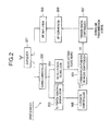
down converter 202 through aduplexer 201. Thedown converter 202 converts the received rf uplink signal to a baseband signal and outputs it to both a transmission powercontrol signal demodulator 203 and a base stationselection signal demodulator 204. The transmission powercontrol signal demodulator 203 demodulates the transmission power control signal from the received baseband signal and outputs it to atransmission power controller 205. The base stationselection signal demodulator 204 demodulates the base station selection signal from the received baseband signal and outputs it to a primary/non-primary basestation mode controller 206. - The
transmission power controller 205 produces an interim controlled transmission power value P1 depending on the transmission power control signal inputted from the transmission powercontrol signal demodulator 203 and outputs the interim controlled transmission power value P1 to the primary/non-primary basestation mode controller 206. - The primary/non-primary base
station mode controller 206 updates the interim controlled transmission power value P1 depending on the base station selection signal to produce a final controlled transmission power value P2 and output it to atransmission controller 207. The details of the primary/non-primary basestation mode controller 206 will be described later. - The
transmission controller 207 receives a downlink transmission signal and performs the output power control such that the transmission power of the downlink transmission signal is set to the final controlled transmission power value P2. The power-controlled downlink transmission signal is converted into radio frequency by anup converter 208. The rf downlink transmission signal is amplified by therf amplifier 209 and then transmitted to the mobile station through theduplexer 201. - Referring to Fig. 3A, a transmission signal between the mobile station and multiple base stations has a frame structure. A frame D-001 consists of Fn slots to which consecutive numbers from 0 to Fn-1 are assigned, respectively.
- As described above, the mobile station transmits the base station selection signal for soft handover to the base stations which it is communicating with. The base station selection signal is composed of a string of bits identifying each of the base stations. Since a plurality of bits are used to form a base station selection signal, redundancy can be provided, resulting in reduced transmission error due to noises and/or fading.
Hereinafter, a string of 8 bits identifying each of the base stations is called "a base station selection code word". An example will be described with reference to Fig. 3B. - As shown in Fig. 3B, assuming that a base station selection code word E-002 is "00001111", each part of the code word E-002 is assigned to the dedicated field E-001 of a different uplink slot E-003. In other words, the base station selection code word E-002 is divided into 8 parts (here, each part is one bit) and the respective 8 parts are transmitted by the dedicated fields E-001 of different slots E-003. Here, a period of base station selection control E-004 is 8 slots, each of which has the desiccated field E-001 for storing a corresponding bit of the 8-bit base station selection code word E-002. It is possible to accommodate two or more bits of the base station selection code word E-002. The larger the number of bits to be accommodated, the shorter the period of base station selection control E-004.
- In the cellular system, each base station and each mobile station measure intensities of pilot signals and interference signals received from adjacent cells at regular intervals in order to use them for handover control and call admission control. In the case where a base station performs the measuring of pilot signals and interference signals, the uplink transmission of each mobile station connected to the base station is temporarily halted to allow the precise measuring of signals from outside cells. Further, there are some cases where the uplink transmission of a mobile station is halted during communication so as to suppress uplink interference in the case of packet transmission and no-voice transmission.
- As described before, the primary/non-primary base
station mode controller 206 in each of the base stations updates the Interim controlled transmission power value P1 depending on the base station selection code word E-002 to produce a final controlled transmission power value P2 The conventional base station mode control is performed as shown in Fig. 4. - Referring to Fig. 4, the primary/non-primary base
station mode controller 206 inputs the base station selection code word E-002 from the base station selection signal demodulator 204 (step S401) and detects the base station identification number BS_IDRSV from the base station selection code word E-002 (step S402). Then, it is determined whether the base station identification number BS_IDKSV is identical to the identification number ID of its own (step S403). If the base station identification number BS_IDRSV is identical to the own identification number ID (YES at step S403), then the final controlled transmission power value P2 is set to the interim controlled transmission power value P1 inputted from thetransmission power controller 205, that is, P2=P1 (primary base station mode), (step S404). If the base station identification number BS_IDRSV is not identical to the own identification number ID (NO at step S403), then the final controlled transmission power value P2 is set to a predetermined minimum transmission power value PMIN, that is, P2= PMIN (non-primary base station mode), (step S405). The predetermined minimum transmission power value PMIN may be 0. The final controlled transmission power value P2 is output to the transmission controller 207 (step S406). - In this manner, at each of the base stations communicating with the mobile station, the transmission power selectively switches on and off depending on the base station selection code word E-002 received from the mobile station. Accordingly, multiple base stations are prevented from simultaneously transmitting the same signal to a single mobile station and thereby interference to adjacent cells is suppressed, resulting in improved communication capacity.
- In the case where the uplink transmission of each mobile station connected to the base station is temporarily halted as described before, however, the base station selection code word E-002 to be transmitted to the base stations is punctured in part or in entirety as shown in Fig. 3C.
- More specifically, when the uplink transmission of the mobile station is halted for an uplink transmission puncturing period F-001 in the base station control period E-004, the base station selection code word E-002 is punctured in part and an incomplete code word F-002 is received at the base stations. Such a partial or entire loss of the base station selection code word E-002 results in substantially reduced reliability on base station selection control.
- As described before, during the soft handover operation, a plurality of base stations transmit the same signal to a single mobile station. In this case, the transmission timing of the signal is adjusted so that the signals transmitted by the base stations arrive at the mobile station within an acceptable time deviation. Since propagation distances from the mobile station to the base stations vary from base station to base station, the respective transmission timings of the base stations are different, On the other hand, the base stations also receive the uplink signal from the mobile station at different timings due to the different propagation distances.
- In the case where the respective transmission timings of the downlink signals and the receiving timings of the uplink signal including the base station selection signal at the base stations are different as described above, there are cases where actual BS mode update timings of the base stations vary from base station to base station. The details will be described hereinafter.
- Referring to Fig. 5, a time slot is denoted by reference symbol G-001 and each transmission signal has a frame structure where 15 slots are numbered from 0 to 14. For simplicity, it is assumed that two
base stations - Accordingly, the mobile station receives the downlink transmission signals G-002 as a downlink reception signal G-004 from the
base station 1 and, at the approximately same time, receives the downlink transmission signals G-003 as a downlink reception signal G-005 from thebase station 2. - The mobile station transmits an uplink transmission signal G-006 to the
base stations 1, and 2 a time period of transmission timing offset TTR after the downlink reception signals G-004 and G-005 have been received. As described before, the uplink transmission signal G-006 includes the base station selection code word such that respective parts of the base station selection code word are conveyed in the dedicated fields as shown in Fig. 3B. - The
base station 2 receives the uplink transmission signal G-006 as an uplink reception signal G-007 with a propagation delay time of D3 and thebase station 1 receives the uplink transmission signal G-006 as an uplink reception signal G-008 with a propagation delay time of D4. - It is assumed that an entire base station selection code word is received when the slot numbered 14 has been received. In this case, the
base station 2 starts the primary/non-primary BS mode update operation as shown in Fig. 4 when receiving the last part of the base station selection code word stored in the dedicated field G-020 in the slot numbered 14 of the uplink reception signal G-007 . As shown in Fig. 5, the timing of receiving the last part of the base station selection code word falls into the subsequent slot numbered 0. Therefore, the actual primary/non-primary mode update is performed at the further subsequent slot G-017 numbered 1. - Similarly, the
base station 1 starts the primary/non-primary BS mode update operation as shown in Fig. 4 when receiving the last part of the base station selection code word stored in the dedicated field G-021 in the slot numbered 14 of the uplink reception signal G-008. As shown in Fig. 5, the timing of receiving the last part of the base station selection code word falls into the next slot but one, that is numbered 1. Therefore, the actual primary/non-primary mode update is performed at the further next slot numbered 2. - In this manner, from the standpoint of the mobile station, the primary base station update timing of the
base station 1 is the slot G-018 numbered 2 and that of thebase station 2 is the slot G-019 numbered 1. Since the BS selection code word is transmitted during a period of base station selection control, variations in BS mode update timing may cause loss of a downlink signal. To avoid such a signal loss, the mobile station needs an added circuit for monitoring the BS mode update timing at all times. - An object of the present invention is to provide a transmission power control method and system allowing stable and reliable signal transmission.
- Another object of the present invention is to provide a primary base station mode update method ensuring stable and reliable operation in case of loss of a base station selection signal.
- Still another object of the present Invention is to provide a primary base station mode update method allowing synchronization among the mode update timings of base stations communicating with a mobile station.
- According to an aspect of the present invention, a method for controlling transmission power of a downlink signal from a base station to a mobile station depending on a base station selection signal, wherein the mobile station selects at least one primary base station among a plurality of base stations which are connected to the mobile station for soft handover to produce the base station selection signal designating said at least one primary base station, includes the steps of: at each of the base stations, receiving the base station selection signal from the mobile station; measuring an amount of loss of the base station selection signal; determining whether the amount of loss of the base station selection signal exceeds a threshold; when the amount of loss of the base station selection signal does not exceed the threshold, setting the transmission power of the downlink signal to a selected one of a normally controlled level and a minimum level depending on the base station selection signal; and when the amount of loss of the base station selection signal exceeds the threshold, setting the transmission power of the downlink signal to the normally controlled level.
- The amount of loss of the base station selection signal may be a number of erroneously received bits in the base station selection signal. The amount of loss of the base station selection signal may be a ratio of a punctured length to a length of the base station selection signal. The threshold may vary depending on a length of the base station selection signal. The threshold may vary depending on the length of the base station selection signal.
- According to anther aspect of the present invention, a method for controlling transmission power of a downlink signal which is transmitted in frames from a base station to a mobile station depending on a base station selection signal, wherein the mobile station selects at least one primary base station among a plurality of base stations which are connected to the mobile station for soft handover to produce the base station selection signal designating said at least one primary base station, wherein an uplink signal including the base station selection signal is transmitted in frames to the base stations, the method includes the steps of: at each of the base stations, a) receiving the uplink signal including the base station selection signal from the mobile station; b) determining a transmission power update timing so that the downlink signal received at the mobile station changes in transmission power at a predetermined timing synchronized with that of other base stations; and c) when reaching the transmission power update timing, setting the transmission power of the downlink signal to a selected one of a normally controlled level and a minimum level depending on the base station selection signal.
- Each frame of the uplink signal and the downlink signal may be composed of a plurality of time slots which are numbered consecutively, wherein the transmission power update timing in each of the base stations is represented by a number of same time slot.
- The time slot number indicating the transmission power update timing may be determined by delaying a receiving time of the base station selection signal by an amount of time determined so that the downlink signal received at the mobile station changes In transmission power at same timing.
- The time slot number indicating the transmission power update timing is preferably determined by

where is number of a time slot indicating a last portion of the base station selection signal, Tos is waiting time for transmission power update. Fn is number of slots included in one frame, and mod is an operator whose result is the remainder of a division operation. - The waiting time Tos may vary depending on a propagation delay between the base station and the mobile station. The waiting time Tos may vary depending on the time slot number j.
- As described above, according to the present invention, when the amount of loss of a base station selection signal received from a mobile station exceeds a predetermined level, the base station mode does not reduce the transmission power of the downlink signal regardless of whether the base station selection signal instructs the base station itself to be the primary base station or not. Therefore, base station selection error due to a low-reliable base station selection signal can be avoided. Especially, in the case where a base station is designated as the primary base station, it is avoided that the base station erroneously reduces or switches off the transmission power.
- Further, since the update timings of the base stations are in synchronization with each other in the downlink signal received at the mobile station, loss of a downlink signal caused by loss of synchronism can be avoided without the need of an added circuit for monitoring the mode update timing at the mobile station.
- Fig. 1 is a schematic diagram showing a configuration of a mobile station in a mobile communications system;
- Fig. 2 is a schematic diagram showing a configuration of a base station in the mobile communications system;
- Fig. 3A is a diagram showing a frame format of an uplink signal transmitted from a mobile station to a base station;
- Fig. 3B is a diagram showing the frame format of an uplink signal for explaining a method of transmitting a base-station selection signal;
- Fig. 3C is a diagram showing the frame format of an uplink signal for explaining an uplink transmission stop period;
- Fig. 4 is a flow chart showing a conventional method of updating the primary/non-primary base station mode;
- Fig. 5 is a time chart showing the base-station mode update timing in the conventional method;
- Fig. 6 is a flow chart showing a method of updating the primary/non-primary base station mode according to a first embodiment of the present invention;
- Fig. 7 is a flow chart showing a method of updating the primary/non-primary base station mode according to a second embodiment of the present invention ;
- Fig. 8 is a time chart showing the base-station mode update timing according to the second embodiment; and
- Fig. 9 is a flow chart showing a method of updating the primary/non-primary base station mode according to a third embodiment of the present invention.
- The preferred embodiments of the present invention will be described in detail with reference to Figs. 6-9. Each of the embodiments will be described as a control operation of the primary/non-primary base
station mode controller 206 at a base station, which may be Implemented by a control program running on a program-controlled processor in the primary/non-primary basestation mode controller 206. - As described before, the primary/non-primary base
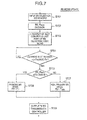
station mode controller 206 in each of the base stations updates the interim controlled transmission power value P1 depending on the base station selection code word E-002 to produce a final controlled transmission power value P2. - Referring to Fig. 6. a first embodiment of the present invention controls the transmission power taking into consideration the amount of loss of a base station selection signal or code word.
- More specifically, the primary/non-primary base
station mode controller 206 inputs the base station selection code word from the base station selection signal demodulator 204 (step S601) and measures the amount of loss of the base station selection code word (step 5602) . The amount of loss of the base station selection code word may be the number of punctured bits as shown in Fig. 3C or the ratio of the number of punctured bits to the number of all bits of the base station selection code word. Hereafter, the amount of loss of the base station selection code word is denoted by LCW. - Subsequently, it is determined whether the amount of loss of the base station selection code word, LCW, is greater than a threshold LTH (step S603). The threshold LTH may vary depending on the length of the base station selection code word.
- If LCW > LTH (YES at step S603), then it is determined that the demodulated base station selection code word is not sufficiently reliable and the final controlled transmission power value P2 is set to the interim controlled transmission power value P1 inputted from the
transmission power controller 205, that is, P2=P1 (primary base station mode), (step S604). In other words, the transmission power is not suppressed regardless of whether the base station itself is the primary base station or not. - If LCW is equal to or lower than LTH (NO at step 5603), then the base station identification number BS_IDRSV is detected from the base station selection code word (step S605). Then, it is determined whether the base station identification number BS_IDRSV is identical to the identification number ID of its own (step S606).
- If the base station identification number BS_IDRSV is identical to the own identification number ID (YES at step S606), then the final controlled transmission power value P2 is set to the interim controlled transmission power value P1, that is, P2=P1 (primary base station mode), (step S604). If the base station identification number BS_IDRSV is not identical to the own identification number ID (NO at step S606), then the final controlled transmission power value P2 is set to a predetermined minimum transmission power value PMIN, that is, P2= PMIN (non-primary base station mode), (step S607). The predetermined minimum transmission power value PMIN may be 0. The final controlled transmission power value P2 is output to the transmission controller 207 (step S608).
- Alternatively, if the base station identification number BS_IDRSV is not identical to the own identification number ID (NO at step S606), it may be further determined whether the reception quality of the base station selection code word satisfies a predetermined level. If the reception quality does not satisfy the predetermined level, then it is determined that the demodulated base station selection code word is not sufficiently reliable, and the final controlled transmission power value P2 may be set to the interim controlled transmission power value P1 (step S604).
- As described above, in the case where the amount of loss of the base station selection code word is greater than the threshold, in other words, where the demodulated base station selection code word is not sufficiently reliable, the transmission power is not suppressed regardless of whether the base station itself is designated as the primary base station or not.
- Referring to Fig. 7, a second embodiment of the present invention controls the BS mode update timing so that synchronization among the primary/non-prinzary mode update timings of base stations is achieved.
- More specifically, the primary/non-primary base
station mode controller 206 inputs the base station selection code word from the base station selection signal demodulator 204 (step S701) and detects the base station identification number BS_IDRSV from the base station selection code word E-002 (step S702). Then, variable i is set to the number of a current slot and variable j is set to the number of a slot conveying the last part of the base station selection code word (step S703) . Thereafter, it is determined whether the following equation (1) is satisfied (step S704):
where Tos is waiting time for mode update, Fn is the number of slots included in one frame, and X mod Y is an operator whose result is the remainder of a division operation (X/Y). In other words, the base station mode updating operation is not performed until the current slot reaches a slot numbered (j + Tos) mod Fn. - When the equation (1) is satisfied (YES at step S704), it is determined whether the base station identification number BS_IDRSV is identical to the identification number ID of its own (step S705). If the base station identification number BS_IDRSV is identical to the own identification number ID (YES at step S705), then the final controlled transmission power value P2 is set to the interim controlled transmission power value P1 inputted from the
transmission power controller 205, that is, P2=P1 (primary base station mode), (step S706). If the base station identification number BS_IDRSV is not identical to the own identification number ID (NO at step 5705), then the final controlled transmission power value P2 is set to a predetermined minimum transmission power value PMIN. that is, P2= PMIN (non-primary base station mode), (step S707). The predetermined minimum transmission power value PMIN may be 0. The final controlled transmission power value P2 is output to the transmission controller 207 (step S708). - Alternatively, if the base station identification number BS_IDRSV is not identical to the own identification number ID (NO at step S705), it may be further determined whether the reception quality of the base station selection code word satisfies a predetermined level. If the reception quality does not satisfy the predetermined level, then it is determined that the demodulated base station selection code word is not sufficiently reliable, and the final controlled transmission power value P2 may be set to the interim controlled transmission power value P1 (step S706).
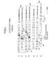
- Referring to Fig. 8, a time slot is denoted by reference symbol J-001 and each transmission signal has a frame structure where Fn (=15) slots are numbered from 0 to 14. For simplicity, it is assumed that two
base stations - Accordingly, the mobile station receives the downlink transmission signals J-002 as a downlink reception signal J-004 from the
base station 1 and, at the approximately same time, receives the downlink transmission signals J-003 as a downlink reception signal J-005 from thebase station 2. - The mobile station transmits an uplink transmission signal J-006 to the
base stations 1 and 2 a time period of transmission timing offset TTR after the downlink reception signals J-004 and J-005 have been received. As described before, the uplink transmission signal J-006 includes the base station selection code word such that respective parts of the base station selection code word are conveyed in the dedicated fields as shown in Fig. 3B. - The
base station 2 receives the uplink transmission signal J-006 as an uplink reception signal J-007 with a propagation delay time of D3 and thebase station 1 receives the uplink transmission signal J-006 as an uplink reception signal J-008 with a propagation delay time of D4. - It is assumed that an entire base station selection code word is received when the slot numbered 14 has been received, that is, j = 14, and the mode update waiting time Tos is set to 3, Fn = 15. In this case, (j + Tos) mod Fn = 2. Therefore, the
base station 1 performs the actual mode update at the slot J-017 numbered 2. Similarly, the base station I also performs the actual mode update at the slot J-017 numbered 2. - In this manner, from the standpoint of the mobile station, the primary base station update timing of the
base station 1 is in synchronization with that of thebase station 2. - It is preferable that the waiting time Tos is as short as possible to achieve high-speed mode switching. Since the propagation delay and processing delay in a base station may vary, it is possible to make the waiting time Tos variable during communication.
- Further, the waiting time Tos may be varied depending on the number j of the slot conveying the last part of the base station selection code word. In this case, the primary base station mode update timing at the mobile station can be set to a desired timing.
- Referring to Fig. 9, a third embodiment of the present invention is a combination of the first and second embodiments. Steps S901-S905 are the same as the steps S701-S705 of Fig. 7, respectively. If the base station identification number BS_IDREV is identical to the own identification number ID (YES at step S905), then it is determined whether the amount of loss of the base station selection code word, LCW, is greater than a threshold LTH (step S906).
- If LCW > LTH (YES at step S906), then it is determined that the demodulated base station selection code word is not sufficiently reliable and the final controlled transmission power value P2 is set to the interim controlled transmission power value P1 inputted from the
transmission power controller 205, that is, P2=P1 (primary base station mode), (step S604). In other words, Lhe transmission power is not suppressed regardless of whether the base station itself is the primary base station or not. - if LCW is equal to or lower than LTH (NO at step S906), then the final controlled transmission power value P2 is set to a predetermined minimum transmission power value PMIN, that is, P2= PMIN (non-primary base station mode), (step S908). The final controlled transmission power value P2 is output to the transmission controller 207 (step S909).
- Alternatively, if the base station identification number BS_IDRSV is not identical to the own identification number ID (NO at step S905), it may be further determined whether the reception quality of the base station selection code word satisfies a predetermined level. If the reception quality does not satisfy the predetermined level, then it is determined that the demodulated base station selection code word is not sufficiently reliable, and the final controlled transmission power value P2 may be set to the interim controlled transmission power value P1 (step S907).
- As described above, according to the present invention, when the amount of loss of a base station selection signal received from a mobile station exceeds a predetermined level due to an uplink puncturing operation of the mobile station, the base station mode is set to the primary mode regardless of whether the base station selection signal instructs the base station itself to be the primary base station or not. Therefore, such a decision error that the base station is erroneously set to the non-primary base station mode due to reception error can be effectively eliminated, resulting in stable and reliable quality of a downlink signal from the base station to the mobile station.
- Further, since the update timings of the base stations are in synchronization with each other in the downlink signal received at the mobile station, loss of a downlink signal caused by loss of synchronism can be avoided without the need of an added circuit for monitoring the mode update timing at the mobile station.
Claims (18)
- A method for determining a mode of a base station as primary or non-primary, wherein the base station is connected with a mobile station for soft handover, comprising the steps of :receiving a base station identification code from the mobile station;
characterized bymeasuring an amount of loss of the received base station identification code; anddetermining the mode of the base station as non-primary when the received base station identification code is not identical to the base station identification code of the receiving base station and if the amount of loss of the received base station identification code is less than a threshold. - The method according to claim 1, further comprising the step of:determining the mode of the base station as primary when the received base station identification code is identical to the base station identification code of the receiving base station or if the amount of loss of the base station identification code exceeds the threshold.
- The method according to claim 1 or 2, wherein the amount of loss of the received base station identification code is a number of erroneously received bits in the base station identification code.
- The method according to claim 1 or 2, wherein the amount of loss of the received base station identification code is a ratio of a punctured length to a length of the received base station identification code.
- The method according to claim 1, 2, 3 or 4, wherein the threshold varies depending on a length of the received base station identification code.
- A device for determining a mode of a base station as primary or non-primary, wherein the base station is connected with a mobile station for soft handover, comprising:a receiver for receiving a base station identification code from the mobile station;
characterized bya controller for determining the mode of the base station by:measuring an amount of loss of the received base station identification code; anddetermining the mode of the base station as non-primary when the received base station identification code is not identical to the base station identification code of the receiving base station and if the amount of loss of the received base station identification code is less than a threshold. - The device according to claim 6, wherein the controller further determines the mode of the base station as primary when the received base station identification is identical to the base station identification code of the receiving base station or if the amount of loss of the base station identification code exceeds the threshold.
- The device according to claim 6 or 7, wherein the amount of loss of the received base station identification code is a number of erroneously received bits in the base station identification code.
- The device according to claim 6 or 7, wherein the amount of loss of the received base station identification code is a ratio of a punctured length to a length of the received base station identification code.
- The device according to claim 6, 7, 8 or 9, wherein the threshold varies depending on a length of the received base station identification code.
- A method for controlling transmission power of a downlink signal from a base station to a mobile station depending on a base station selection signal, wherein the mobile station selects at least one primary base station among a plurality of base stations which are connected to the mobile station for soft handover to produce the base station selection signal designating said at least one primary base station, comprising the steps of :at each of the base stations,receiving the base station selection signal from the mobile station;
characterized bymeasuring an amount of loss of the base station selection signal :determining whether the amount of loss of the base station selection signal exceeds a threshold;when the amount of loss of the base station selection signal does not exceed the threshold, setting the transmission power of the downlink signal to a selected one of a normally controlled level and a minimum level depending on the base station selection signal; andwhen the amount of loss of the base station selection signal exceeds the threshold, setting the transmission power of the downlink signal to the normally controlled level. - The method according to claim 11,wherein the amount of loss of the base station selection signal is a number of erroneously received bits in the base station selection signal.
- The method according to claim 11,wherein the amount of loss of the base station selection signal is a ratio of a punctured length to the length of the base station selection signal.
- The method according to claim 11, 12 or 13, wherein the threshold varies depending on the length of the base station selection signal.
- A device for controlling transmission power of a downlink signal depending on a base station selection signal in each of base stations of a mobile communications system, wherein a mobile station selects at least one primary base station among a plurality of base stations which are connected to the mobile station for soft handover to produce the base station selection signal designating said at least one primary base station, comprising:a receiver for receiving the base station selection signal from the mobile station;
characterized bya controller for controlling the transmission power of the downlink signal to the mobile station bymeasuring an amount of loss of the base station selection signal;determining whether the amount of loss of the base station selection signal exceeds a threshold;when the amount of loss of the base station selection signal does not exceed the threshold, setting the transmission power of the downlink signal to a selected one of a normally controlled level and a minimum level depending on the base station selection signal; andwhen the amount of loss of the base station selection signal exceeds the threshold, setting the transmission power of the downlink signal to the normally controlled level. - The device according to claim 15, wherein the amount of loss of the base station selection signal is a number of erroneously received bits in the base station selection signal.
- The device according to claim 15, wherein the amount of loss of the base station selection signal is a ratio of a punctured length to the length of the base station selection signal.
- The device according to claim 15, 16 or 17, wherein the threshold varies depending on the length of the base station selection signal.
Applications Claiming Priority (2)
| Application Number | Priority Date | Filing Date | Title |
|---|---|---|---|
| JP35341899A JP3365379B2 (en) | 1999-12-13 | 1999-12-13 | Base station selective transmission power control method and base station apparatus |
| EP00123392A EP1109330B1 (en) | 1999-12-13 | 2000-10-31 | Transmission power control method and system |
Related Parent Applications (2)
| Application Number | Title | Priority Date | Filing Date |
|---|---|---|---|
| EP00123392A Division EP1109330B1 (en) | 1999-12-13 | 2000-10-31 | Transmission power control method and system |
| EP00123392.3 Division | 2000-10-31 |
Publications (3)
| Publication Number | Publication Date |
|---|---|
| EP1770872A2 true EP1770872A2 (en) | 2007-04-04 |
| EP1770872A3 EP1770872A3 (en) | 2013-09-11 |
| EP1770872B1 EP1770872B1 (en) | 2019-08-28 |
Family
ID=18430713
Family Applications (5)
| Application Number | Title | Priority Date | Filing Date |
|---|---|---|---|
| EP00123392A Expired - Lifetime EP1109330B1 (en) | 1999-12-13 | 2000-10-31 | Transmission power control method and system |
| EP06126923.9A Expired - Lifetime EP1770872B1 (en) | 1999-12-13 | 2000-10-31 | Transmission power control method and system |
| EP04017733A Expired - Lifetime EP1478102B1 (en) | 1999-12-13 | 2000-10-31 | Transmission power control method and system |
| EP10182024.9A Expired - Lifetime EP2296411B1 (en) | 1999-12-13 | 2000-10-31 | Transmission power control method and system |
| EP10180369.0A Expired - Lifetime EP2293628B1 (en) | 1999-12-13 | 2000-10-31 | Transmission power control method and system |
Family Applications Before (1)
| Application Number | Title | Priority Date | Filing Date |
|---|---|---|---|
| EP00123392A Expired - Lifetime EP1109330B1 (en) | 1999-12-13 | 2000-10-31 | Transmission power control method and system |
Family Applications After (3)
| Application Number | Title | Priority Date | Filing Date |
|---|---|---|---|
| EP04017733A Expired - Lifetime EP1478102B1 (en) | 1999-12-13 | 2000-10-31 | Transmission power control method and system |
| EP10182024.9A Expired - Lifetime EP2296411B1 (en) | 1999-12-13 | 2000-10-31 | Transmission power control method and system |
| EP10180369.0A Expired - Lifetime EP2293628B1 (en) | 1999-12-13 | 2000-10-31 | Transmission power control method and system |
Country Status (6)
| Country | Link |
|---|---|
| US (4) | US6847818B1 (en) |
| EP (5) | EP1109330B1 (en) |
| JP (1) | JP3365379B2 (en) |
| KR (1) | KR100353746B1 (en) |
| CA (1) | CA2324727C (en) |
| DE (1) | DE60034759T2 (en) |
Families Citing this family (22)
| Publication number | Priority date | Publication date | Assignee | Title |
|---|---|---|---|---|
| US6996078B2 (en) | 2000-07-27 | 2006-02-07 | Interdigital Technology Corporation | Adaptive uplink/downlink timeslot assignment in a hybrid wireless time division multiple access/code division multiple access communication system |
| JP3543323B2 (en) * | 2001-02-14 | 2004-07-14 | 日本電気株式会社 | Base station transmission control method, cellular system and base station |
| CN1162028C (en) | 2001-07-18 | 2004-08-11 | 华为技术有限公司 | Method for recognizing primary small region under selective diversity transmitting of base station |
| GB0120033D0 (en) * | 2001-08-16 | 2001-10-10 | Fujitsu Ltd | Cell selection |
| US6591109B2 (en) | 2001-08-17 | 2003-07-08 | Interdigital Technology Corporation | Cross cell user equipment interference reduction in a time division duplex communication system using code division multiple access |
| JP4012391B2 (en) * | 2001-10-30 | 2007-11-21 | 株式会社エヌ・ティ・ティ・ドコモ | Mobile station, mobile communication system, handover control method, handover control program, and recording medium |
| GB2382956B (en) * | 2001-12-05 | 2006-03-01 | Ipwireless Inc | Method and arrangement for power control |
| US7280842B2 (en) | 2001-12-17 | 2007-10-09 | Marvell International Ltd. | Wireless communication device and method for communicating in site selection diversity mode |
| US20030114179A1 (en) * | 2001-12-17 | 2003-06-19 | D.S.P.C. Technologies Ltd. | Method and apparatus for generating a quality measure target value based on channel conditions |
| JP4147780B2 (en) * | 2002-02-12 | 2008-09-10 | 日本電気株式会社 | Quality threshold setting method and communication control apparatus using the same |
| JP4014893B2 (en) * | 2002-03-01 | 2007-11-28 | 株式会社エヌ・ティ・ティ・ドコモ | Wireless communication system for multi-hop connection, wireless communication method, and wireless station used therefor |
| US7515883B1 (en) | 2002-12-16 | 2009-04-07 | Marvell D.S.P.C. Ltd. | Wireless communication device and method for communicating in site selection diversity mode |
| KR100964669B1 (en) * | 2003-05-10 | 2010-06-22 | 엘지전자 주식회사 | Mobile Communication System and Method of Designing a MAC Channel at the Mobile Communication System |
| US7953411B1 (en) * | 2004-06-09 | 2011-05-31 | Zte (Usa) Inc. | Virtual soft hand over in OFDM and OFDMA wireless communication network |
| US7536626B2 (en) * | 2004-06-18 | 2009-05-19 | Qualcomm Incorporated | Power control using erasure techniques |
| ES2294436T3 (en) * | 2004-12-02 | 2008-04-01 | Swisscom Mobile Ag | MOBILE PHONE CELL NETWORK AND PROCEDURE FOR THE ESTABLISHMENT OF A BASE STATION OF A MOBILE PHONE CELL NETWORK IN AN INSTALLATION SUPPLIED BY AN ELECTRICAL NETWORK. |
| US20070110035A1 (en) * | 2005-11-14 | 2007-05-17 | Broadcom Corporation, A California Corporation | Network nodes cooperatively routing traffic flow amongst wired and wireless networks |
| US7647050B2 (en) * | 2005-12-28 | 2010-01-12 | Alcatel-Lucent Usa Inc. | Method of adjusting a power level of communications over a channel in a wirelss communications network |
| WO2009044458A1 (en) * | 2007-10-02 | 2009-04-09 | Fujitsu Limited | Handover control device, mobile station, base station, handover control server, and handover control method |
| CN102017682B (en) | 2009-04-17 | 2013-08-07 | 华为技术有限公司 | Downlink inter-cell interference coordination method and base station |
| CN102545992B (en) * | 2011-12-21 | 2014-07-23 | 北京邮电大学 | Optimal relay selection and power distribution method of DF (decode-forward) relay system |
| JP2017085473A (en) * | 2015-10-30 | 2017-05-18 | 富士通株式会社 | Transmission system, radio equipment, and synchronization establishment method |
Citations (4)
| Publication number | Priority date | Publication date | Assignee | Title |
|---|---|---|---|---|
| WO1998049785A1 (en) * | 1997-04-25 | 1998-11-05 | Qualcomm Incorporated | Method of and apparatus for controlling transmission power in a communication system |
| WO1998059433A2 (en) * | 1997-06-23 | 1998-12-30 | Telefonaktiebolaget Lm Ericsson | Method and apparatus for downlink power control in macro diversity radio systems |
| WO1999031819A1 (en) * | 1997-12-15 | 1999-06-24 | Telefonaktiebolaget Lm Ericsson (Publ) | Base station transmit power control in a cdma cellular telephone system |
| EP0936751A2 (en) * | 1998-02-16 | 1999-08-18 | Nec Corporation | Base station transmission power control during soft hand over, mobile station and base station |
Family Cites Families (5)
| Publication number | Priority date | Publication date | Assignee | Title |
|---|---|---|---|---|
| JP2911090B2 (en) * | 1993-09-29 | 1999-06-23 | エヌ・ティ・ティ移動通信網株式会社 | Mobile communication base station device and mobile station device |
| JP2739850B2 (en) * | 1995-10-11 | 1998-04-15 | 日本電気株式会社 | Mobile communication system |
| US6141555A (en) * | 1997-06-09 | 2000-10-31 | Nec Corporation | Cellular communication system, and mobile and base stations used in the same |
| JP3147850B2 (en) | 1998-03-26 | 2001-03-19 | 日本電気株式会社 | Mobile communication system, communication control method therefor, base station and mobile station used therefor |
| JP3750390B2 (en) * | 1999-01-08 | 2006-03-01 | 日本電気株式会社 | Call control method and system in mobile communication |
-
1999
- 1999-12-13 JP JP35341899A patent/JP3365379B2/en not_active Expired - Lifetime
-
2000
- 2000-10-30 CA CA002324727A patent/CA2324727C/en not_active Expired - Lifetime
- 2000-10-31 KR KR1020000064230A patent/KR100353746B1/en active IP Right Grant
- 2000-10-31 EP EP00123392A patent/EP1109330B1/en not_active Expired - Lifetime
- 2000-10-31 EP EP06126923.9A patent/EP1770872B1/en not_active Expired - Lifetime
- 2000-10-31 DE DE60034759T patent/DE60034759T2/en not_active Expired - Lifetime
- 2000-10-31 EP EP04017733A patent/EP1478102B1/en not_active Expired - Lifetime
- 2000-10-31 EP EP10182024.9A patent/EP2296411B1/en not_active Expired - Lifetime
- 2000-10-31 EP EP10180369.0A patent/EP2293628B1/en not_active Expired - Lifetime
- 2000-10-31 US US09/703,052 patent/US6847818B1/en not_active Expired - Lifetime
-
2004
- 2004-01-23 US US10/762,356 patent/US7242959B2/en not_active Expired - Lifetime
-
2007
- 2007-06-05 US US11/758,026 patent/US7912493B2/en not_active Expired - Fee Related
-
2011
- 2011-02-10 US US13/024,372 patent/US8478330B2/en not_active Expired - Lifetime
Patent Citations (4)
| Publication number | Priority date | Publication date | Assignee | Title |
|---|---|---|---|---|
| WO1998049785A1 (en) * | 1997-04-25 | 1998-11-05 | Qualcomm Incorporated | Method of and apparatus for controlling transmission power in a communication system |
| WO1998059433A2 (en) * | 1997-06-23 | 1998-12-30 | Telefonaktiebolaget Lm Ericsson | Method and apparatus for downlink power control in macro diversity radio systems |
| WO1999031819A1 (en) * | 1997-12-15 | 1999-06-24 | Telefonaktiebolaget Lm Ericsson (Publ) | Base station transmit power control in a cdma cellular telephone system |
| EP0936751A2 (en) * | 1998-02-16 | 1999-08-18 | Nec Corporation | Base station transmission power control during soft hand over, mobile station and base station |
Also Published As
| Publication number | Publication date |
|---|---|
| US20070232315A1 (en) | 2007-10-04 |
| EP2296411A1 (en) | 2011-03-16 |
| DE60034759T2 (en) | 2008-01-17 |
| US8478330B2 (en) | 2013-07-02 |
| KR20010060230A (en) | 2001-07-06 |
| EP2293628A1 (en) | 2011-03-09 |
| EP1770872B1 (en) | 2019-08-28 |
| US7912493B2 (en) | 2011-03-22 |
| EP1478102B1 (en) | 2011-05-18 |
| US20040152483A1 (en) | 2004-08-05 |
| JP2001169328A (en) | 2001-06-22 |
| CA2324727A1 (en) | 2001-06-13 |
| EP1478102A1 (en) | 2004-11-17 |
| EP1109330A2 (en) | 2001-06-20 |
| EP1109330A3 (en) | 2004-01-02 |
| EP1770872A3 (en) | 2013-09-11 |
| CA2324727C (en) | 2004-12-07 |
| DE60034759D1 (en) | 2007-06-21 |
| EP2293628B1 (en) | 2018-04-04 |
| EP2296411B1 (en) | 2015-04-01 |
| JP3365379B2 (en) | 2003-01-08 |
| US6847818B1 (en) | 2005-01-25 |
| US7242959B2 (en) | 2007-07-10 |
| EP1109330B1 (en) | 2007-05-09 |
| KR100353746B1 (en) | 2002-09-28 |
| US20110130145A1 (en) | 2011-06-02 |
Similar Documents
| Publication | Publication Date | Title |
|---|---|---|
| US8478330B2 (en) | Transmission power control method and system | |
| RU2233035C2 (en) | Power control method and device for broadband code-division multiple access communication system using batch access circuit for direct high-speed link | |
| JP3214466B2 (en) | Mobile communication system, communication control method therefor, base station and mobile station used for the same | |
| EP2071741B1 (en) | Transmission power control method | |
| KR100441330B1 (en) | Base station apparatus and handover control method | |
| KR100734452B1 (en) | Cellular system, base station controller, mobile station, and method for controlling transmittion power used in the same | |
| JP2002010313A (en) | Control method in mobile telecommunication, cellular system, mobile station, base station and base station control equipment | |
| US6907014B1 (en) | Apparatus and method for TDMA-TDD based transmission/reception | |
| EP1626510A2 (en) | Mobile communication system and downlink transmission power control method thereof | |
| US7532591B2 (en) | Radio communication system, radio controller and mobile station | |
| EP1119117A1 (en) | Base station device, communication terminal, and transmission power control method | |
| EP1185124A1 (en) | Mobile station apparatus and radio communication method | |
| CA2452165C (en) | Transmission power control method and system | |
| JP3788307B2 (en) | Base station selective transmission power control method and base station apparatus | |
| JP4604611B2 (en) | Base station selection type transmission power control method, base station apparatus and mobile station | |
| US7171232B2 (en) | Method of selecting a cell to connect by radio with a mobile station and a mobile communications terminal therefor |
Legal Events
| Date | Code | Title | Description |
|---|---|---|---|
| PUAI | Public reference made under article 153(3) epc to a published international application that has entered the european phase |
Free format text: ORIGINAL CODE: 0009012 |
|
| AC | Divisional application: reference to earlier application |
Ref document number: 1109330 Country of ref document: EP Kind code of ref document: P |
|
| AK | Designated contracting states |
Kind code of ref document: A2 Designated state(s): DE FI FR GB IT SE |
|
| REG | Reference to a national code |
Ref country code: HK Ref legal event code: DE Ref document number: 1099968 Country of ref document: HK |
|
| PUAL | Search report despatched |
Free format text: ORIGINAL CODE: 0009013 |
|
| AK | Designated contracting states |
Kind code of ref document: A3 Designated state(s): DE FI FR GB IT SE |
|
| RIC1 | Information provided on ipc code assigned before grant |
Ipc: H04W 52/40 20090101AFI20130806BHEP Ipc: H04W 36/18 20090101ALI20130806BHEP Ipc: H04W 52/24 20090101ALI20130806BHEP Ipc: H04B 7/02 20060101ALI20130806BHEP Ipc: H04W 52/54 20090101ALI20130806BHEP |
|
| 17P | Request for examination filed |
Effective date: 20140311 |
|
| RBV | Designated contracting states (corrected) |
Designated state(s): DE FI FR GB IT SE |
|
| AKX | Designation fees paid |
Designated state(s): DE FI FR GB IT SE |
|
| 17Q | First examination report despatched |
Effective date: 20150728 |
|
| REG | Reference to a national code |
Ref country code: DE Ref legal event code: R079 Ref document number: 60049941 Country of ref document: DE Free format text: PREVIOUS MAIN CLASS: H04B0007005000 Ipc: H04W0052400000 |
|
| GRAP | Despatch of communication of intention to grant a patent |
Free format text: ORIGINAL CODE: EPIDOSNIGR1 |
|
| RIC1 | Information provided on ipc code assigned before grant |
Ipc: H04B 7/022 20170101ALI20190404BHEP Ipc: H04W 52/40 20090101AFI20190404BHEP Ipc: H04B 7/02 20180101ALI20190404BHEP Ipc: H04W 36/18 20090101ALI20190404BHEP Ipc: H04W 52/54 20090101ALI20190404BHEP Ipc: H04W 52/24 20090101ALI20190404BHEP |
|
| INTG | Intention to grant announced |
Effective date: 20190423 |
|
| GRAJ | Information related to disapproval of communication of intention to grant by the applicant or resumption of examination proceedings by the epo deleted |
Free format text: ORIGINAL CODE: EPIDOSDIGR1 |
|
| GRAR | Information related to intention to grant a patent recorded |
Free format text: ORIGINAL CODE: EPIDOSNIGR71 |
|
| GRAS | Grant fee paid |
Free format text: ORIGINAL CODE: EPIDOSNIGR3 |
|
| GRAA | (expected) grant |
Free format text: ORIGINAL CODE: 0009210 |
|
| INTC | Intention to grant announced (deleted) | ||
| AC | Divisional application: reference to earlier application |
Ref document number: 1109330 Country of ref document: EP Kind code of ref document: P |
|
| AK | Designated contracting states |
Kind code of ref document: B1 Designated state(s): DE FI FR GB IT SE |
|
| INTG | Intention to grant announced |
Effective date: 20190722 |
|
| REG | Reference to a national code |
Ref country code: GB Ref legal event code: FG4D |
|
| REG | Reference to a national code |
Ref country code: DE Ref legal event code: R096 Ref document number: 60049941 Country of ref document: DE |
|
| PG25 | Lapsed in a contracting state [announced via postgrant information from national office to epo] |
Ref country code: SE Free format text: LAPSE BECAUSE OF FAILURE TO SUBMIT A TRANSLATION OF THE DESCRIPTION OR TO PAY THE FEE WITHIN THE PRESCRIBED TIME-LIMIT Effective date: 20190828 Ref country code: FI Free format text: LAPSE BECAUSE OF FAILURE TO SUBMIT A TRANSLATION OF THE DESCRIPTION OR TO PAY THE FEE WITHIN THE PRESCRIBED TIME-LIMIT Effective date: 20190828 |
|
| PGFP | Annual fee paid to national office [announced via postgrant information from national office to epo] |
Ref country code: DE Payment date: 20191015 Year of fee payment: 20 |
|
| PGFP | Annual fee paid to national office [announced via postgrant information from national office to epo] |
Ref country code: FR Payment date: 20191014 Year of fee payment: 20 |
|
| PG25 | Lapsed in a contracting state [announced via postgrant information from national office to epo] |
Ref country code: IT Free format text: LAPSE BECAUSE OF FAILURE TO SUBMIT A TRANSLATION OF THE DESCRIPTION OR TO PAY THE FEE WITHIN THE PRESCRIBED TIME-LIMIT Effective date: 20190828 |
|
| PGFP | Annual fee paid to national office [announced via postgrant information from national office to epo] |
Ref country code: GB Payment date: 20191031 Year of fee payment: 20 |
|
| REG | Reference to a national code |
Ref country code: DE Ref legal event code: R097 Ref document number: 60049941 Country of ref document: DE |
|
| REG | Reference to a national code |
Ref country code: HK Ref legal event code: WD Ref document number: 1099968 Country of ref document: HK |
|
| PLBE | No opposition filed within time limit |
Free format text: ORIGINAL CODE: 0009261 |
|
| STAA | Information on the status of an ep patent application or granted ep patent |
Free format text: STATUS: NO OPPOSITION FILED WITHIN TIME LIMIT |
|
| 26N | No opposition filed |
Effective date: 20200603 |
|
| REG | Reference to a national code |
Ref country code: DE Ref legal event code: R071 Ref document number: 60049941 Country of ref document: DE |
|
| REG | Reference to a national code |
Ref country code: GB Ref legal event code: PE20 Expiry date: 20201030 |
|
| PG25 | Lapsed in a contracting state [announced via postgrant information from national office to epo] |
Ref country code: GB Free format text: LAPSE BECAUSE OF EXPIRATION OF PROTECTION Effective date: 20201030 |