EP1770871A1 - Device for the capacitive coupling of a data-transmission device to a phase of an electrical power line - Google Patents
Device for the capacitive coupling of a data-transmission device to a phase of an electrical power line Download PDFInfo
- Publication number
- EP1770871A1 EP1770871A1 EP05773887A EP05773887A EP1770871A1 EP 1770871 A1 EP1770871 A1 EP 1770871A1 EP 05773887 A EP05773887 A EP 05773887A EP 05773887 A EP05773887 A EP 05773887A EP 1770871 A1 EP1770871 A1 EP 1770871A1
- Authority
- EP
- European Patent Office
- Prior art keywords
- block
- connection means
- coupling
- coupling device
- power line
- Prior art date
- Legal status (The legal status is an assumption and is not a legal conclusion. Google has not performed a legal analysis and makes no representation as to the accuracy of the status listed.)
- Granted
Links
- 230000008878 coupling Effects 0.000 title claims abstract description 58
- 238000010168 coupling process Methods 0.000 title claims abstract description 58
- 238000005859 coupling reaction Methods 0.000 title claims abstract description 58
- 239000003990 capacitor Substances 0.000 claims abstract description 19
- 230000005540 biological transmission Effects 0.000 claims abstract description 18
- 230000006978 adaptation Effects 0.000 claims abstract description 17
- 238000005538 encapsulation Methods 0.000 claims description 15
- 239000011347 resin Substances 0.000 claims description 12
- 229920005989 resin Polymers 0.000 claims description 12
- 239000004020 conductor Substances 0.000 claims description 10
- 230000000295 complement effect Effects 0.000 claims description 6
- 238000000465 moulding Methods 0.000 claims description 4
- 230000007935 neutral effect Effects 0.000 claims description 2
- 239000000945 filler Substances 0.000 description 5
- 238000010586 diagram Methods 0.000 description 4
- 239000003822 epoxy resin Substances 0.000 description 4
- 238000009413 insulation Methods 0.000 description 4
- 229920000647 polyepoxide Polymers 0.000 description 4
- 239000004848 polyfunctional curative Substances 0.000 description 4
- 238000002347 injection Methods 0.000 description 3
- 239000007924 injection Substances 0.000 description 3
- 238000000034 method Methods 0.000 description 3
- VYPSYNLAJGMNEJ-UHFFFAOYSA-N Silicium dioxide Chemical compound O=[Si]=O VYPSYNLAJGMNEJ-UHFFFAOYSA-N 0.000 description 2
- 239000003086 colorant Substances 0.000 description 2
- 238000004891 communication Methods 0.000 description 2
- 238000005516 engineering process Methods 0.000 description 2
- 239000000203 mixture Substances 0.000 description 2
- 239000000243 solution Substances 0.000 description 2
- 230000003750 conditioning effect Effects 0.000 description 1
- 239000000835 fiber Substances 0.000 description 1
- LNEPOXFFQSENCJ-UHFFFAOYSA-N haloperidol Chemical compound C1CC(O)(C=2C=CC(Cl)=CC=2)CCN1CCCC(=O)C1=CC=C(F)C=C1 LNEPOXFFQSENCJ-UHFFFAOYSA-N 0.000 description 1
- 238000004519 manufacturing process Methods 0.000 description 1
- 239000000463 material Substances 0.000 description 1
- 239000000377 silicon dioxide Substances 0.000 description 1
- 238000003860 storage Methods 0.000 description 1
Images


Classifications
-
- H—ELECTRICITY
- H04—ELECTRIC COMMUNICATION TECHNIQUE
- H04B—TRANSMISSION
- H04B3/00—Line transmission systems
- H04B3/54—Systems for transmission via power distribution lines
- H04B3/56—Circuits for coupling, blocking, or by-passing of signals
-
- H—ELECTRICITY
- H04—ELECTRIC COMMUNICATION TECHNIQUE
- H04B—TRANSMISSION
- H04B2203/00—Indexing scheme relating to line transmission systems
- H04B2203/54—Aspects of powerline communications not already covered by H04B3/54 and its subgroups
- H04B2203/5462—Systems for power line communications
- H04B2203/5483—Systems for power line communications using coupling circuits
Definitions
- the invention relates to a capacitive coupling device of data transmission equipment to a phase of an electrical power line so as to transmit, over said power line, an electrical data signal in a range of frequencies between 3 kHz and 100 MHz, said coupling device being of the type comprising at least the following components:
- the capacitive coupling device to which the invention refers is particularly applicable in the data transmission over power lines technology, known by the initials PLC, meaning "powerline communication".
- This technology allows a high speed data transmission network to be set up using existing low and medium voltage electrical networks as transmission lines, thus obviating the need to lay down specific wiring, such as for example a fiber optics run.
- an existing power line for example a medium voltage line with 24 kV between phases, can simultaneously transmit electrical energy, via a signal at the usual frequency of 50 Hz (or 60 Hz), and a data flow at a higher frequency, between 3 kHz and 100 MHz.
- connection nodes In order to transmit data between two particular points of an electrical power line, connection nodes between one phase in said line and a local data transmission network or end user must be established at said points.
- data transmission equipment responsible for managing the data flow to be transmitted, is connected to said phase via a coupling device the main purpose of which is to adapt the impedances between the power line and the data transmission equipment, while also conditioning the band width of the data signal and providing the necessary electrical protection with respect to the line voltage.
- This invention relates to one of said coupling devices, and in particular to one of the capacitive type, in other words in which the impedances are adapted essentially by a coupling capacitor.
- Some capacitive coupling devices are known that are used by electrical companies to transmit their own data between different points of a high voltage electrical network, normally in order to control the state of the network. Said known devices are made up of various components that are separated physically, have to be fitted separately and then connected together through wiring. It is not easy to fit these known devices, because the fitter must pay particular attention to the location and safety conditions corresponding to each component.
- the aim of the invention is to overcome these drawbacks.
- This aim is obtained by a capacitive coupling device of the type indicated at the beginning, characterized in that it is made up of two blocks that can be coupled together mechanically to form a compact unit:
- the coupling device according to the invention has the advantage that it is compact, once assembled, and considerably easier to fit than the prior art examples.
- the fitter will be able to first position the first block, attaching it to a structure thanks to said attachment means, set up the ground connections, assemble the second block to the first one forming a compact unit, with the guarantee that all the device elements are connected correctly owing to the simple fact that the two blocks are assembled, and finally set up the connection to a phase of the power line.
- the adaptation to the real network conditions is not satisfactory, or if, for example, it is desired to modify the bandwidth for data transmission, it is possible to replace only the first block of the device, maintaining the second block.
- the constitution of the coupling device according to the invention is such that the first block contains all the components that are likely to require adjustment, while the second block only contains the coupling capacitor, the characteristics of which are constant for a particular nominal voltage of the power line to which it must be coupled.
- said first and second blocks are each made in a molded resin encapsulation, where said encapsulations only leave accessible those parts intended for connection or attachment, that is the ground connection means, the equipment connection means, the structure attachment means, the line connection means, the mutual electrical connection means and the mutual mechanical coupling means.
- the resins constituting the encapsulations are preferably epoxy resins with hardener fillers, which have the advantage that they can be suitably molded and have a high mechanical strength and a high dielectric rigidity.
- said first block comprises a printed circuit board that houses at least one part of said protection, tuning and adaptation means, with the resin constituting said encapsulation of the first block being a resin that is suitable for cold molding and said resin being applied in direct contact with said printed circuit board.
- the encapsulation of said second block has an external shape in the form of a cylindrical or conical housing made up of a series of concentric, truncated bells the purpose of which is to extend the creepage distance and thus increase the flashover voltage.
- the thus formed encapsulation therefore has the double function of structural container for the second block and insulation protection against surges in the power line.
- the encapsulation of the first block has a cylindrical or conical external shape with one lower seating surface that houses said structure attachment means, so that the compact unit formed by the two connected blocks also constitutes suitable insulation protection against line surges.
- said mechanical coupling means between the first and second blocks are made from electrically conductive material and also form said mutual electrical connection means. More preferably, said mechanical coupling means are made up, on the one hand, of a threaded shank made from electrically conductive material integral with the first block and electrically connected to the protection, tuning and adaptation means and, on the other hand, of a threaded hole made in a bushing made from electrically conductive material that is housed in the second block and connected to the second end of the coupling capacitor, said threaded shank and said threaded hole being complementary.
- the first block has a top surface in the center of which said threaded shank is provided
- the second block has a bottom surface, complementary to said top surface, in the center of which said threaded orifice is arranged.
- said structure attachment means consist of a mechanical attachment device made from electrically conductive material and also constitute said ground connection means, and preferably said mechanical attachment device consists of a plurality of bolts the shanks of which project through said lower seating surface and the heads of which are applied to said printed circuit board in contact with the parts of said protection, tuning and adaptation means that must have a ground connection.
- said equipment connection means consist of a single connector housed in a recess in said first block.
- This single connector is normally a BNC type connector and it is protected thanks to its location in the recess.
- said line connection means consist of a threaded hole in a bushing made from electrically conductive material and which is housed in said second block and connected to the first end of said coupling capacitor.
- the threaded hole is intended to receive a threaded stud in which the connection cable is attached to a phase of the power line.
- the capacity of said coupling capacitor is greater or equivalent to 0.1 nF and lower or equivalent to 5 nF, with the coupling device according to the invention being suitable for being connected to a phase of an electrical power line whose voltage between phase and neutral is greater or equivalent to 5 kV, in other words that said coupling device is suitable for implementing a PLC communication system over a medium voltage power line run.
- the embodiment shown in Figs. 1 through 4 corresponds to a coupling device intended to couple a data transmission equipment to one of the phases of a three-phase electrical power line.
- the nominal voltage between phases in the power line is 24 kV and the range of frequencies (bandwidth) of the data transmission signal is between 2 MHz and 38 MHz.
- the coupling device is made up of two blocks 1, 2 that can be mechanically coupled together to form a compact unit.
- the first block 1 has a substantially cylindrical shape and comprises protection, tuning and adaptation means 9, connection means 4 to said data transmission equipment and structure attachment means 5, with the latter also being ground connection means.
- Protection, tuning and adaptation means 9 are made up of a drain coil 24, a gas discharger 25 and a tuning circuit 28 arranged on the line connection side and coupled by means of an insulation transformer 27 on the data transmission equipment side, where a gas discharger 26 is also arranged, all according to the electrical diagram shown in Fig. 4.
- Said first block 1 is provided with a threaded, metallic shank 13 that projects in the central position from the top surface 15 of said first block 1 and which, together with a threaded hole 14 in a metallic bushing 19 housed in the second block 2, forms, as will be seen later, electrical connection and mechanical coupling means between the two blocks 1 and 2.
- the connection means to a data transmission equipment consist of a single BNC type connector 4 housed in a recess 18 arranged on the side wall of said first block 1.
- the tuning circuit 28 is arranged on a printed circuit board 12 that is attached to the heads of three metallic bolts 5.
- shanks of these bolts 5 project from the lower seating surface 17 of the first block 1 and its heads are in contact with the parts of said protection, tuning and adaptation means 9 that must have a ground connection, according to the electrical diagram in Fig. 4, so that these bolts 5 form simultaneously structure attachment means and ground connection means.
- the inner end of shank 13 is threaded in a housing in the printed circuit board 12 where it is connected to protection, tuning and adaptation means 9 according to the electrical diagram in Fig. 4.
- This first block 1 is formed in an encapsulation 10 of epoxy resin with hardener fillers and coloring agent, with this resin being of the type that is cold molded. Therefore, the various components of the first block 1 are connected according to the arrangement shown in Fig. 3 and they are placed in a cylindrical shaped mould, where the space of recess 18 is preserved. A cold mixture of said epoxy resin with hardener fillers is cast in said mould, said mixture falling directly onto the printed circuit board 12 that does not have any protection. After the setting process, the next step is stripping the mould and, after a series of finishing operations which basically consist in removing excess material, said first block 1 is obtained in which only the shanks of bolts 5, the BNC type single connector 4 and the threaded shank 13 are accessible.
- the second block 2 comprises a coupling capacitor 6, which in this particular example has a capacity of 2 nF.
- the first end 7 of said capacitor 6 is connected, by a rigid cable 23, to a metallic bushing 20 provided with a threaded hole 3 in the top surface of said second block 2 and which constitutes connection means to a phase of a power line.
- This connection can be made by threading in hole 3 a stud 22 with the corresponding locknuts for attaching to a line connection cable.
- the second end 8 of capacitor 6 is connected via screws to a metallic bushing 19 provided with a threaded hole 14 in the central position of lower surface 16 of said second block 2.
- the threaded hole 14 and the threaded shank 13 are complementary.
- top 15 and bottom 16 surfaces of blocks 1 and 2 are also complementary, which surfaces in this case are circular and flat with an equal diameter.
- the second block 2 is thus coupled to the first block 1 by threading shank 13 into threaded hole 14 until the two surfaces 15 and 16 form an abutment one against the other, forming overall a compact unit.
- This second block 2 is formed in an encapsulation 11 of epoxy resin with hardener, fillers, silica and coloring agent, with this resin being of the hot injection type. Therefore, the capacitor 6 is placed in a hot injection mould connected to bushings 19 and 20 according to the arrangement shown in Fig. 3 and the resin with fillers is hot injected. After the setting process, the part is stripped in hot from the mould, then it is cooled and it is electrically checked. Thus the second block 2 is obtained in which only threaded holes 3 and 14 are accessible.
- the geometry of the injection mould confers the shape of a cylindrical housing to the second block 2, made up of a series of concentric, truncated bell elements 21 whose function is to increase the creepage distance, so that this encapsulation 11 also forms suitable insulation against line surges.
Landscapes
- Engineering & Computer Science (AREA)
- Power Engineering (AREA)
- Computer Networks & Wireless Communication (AREA)
- Signal Processing (AREA)
- Cable Transmission Systems, Equalization Of Radio And Reduction Of Echo (AREA)
- Near-Field Transmission Systems (AREA)
Abstract
Description
- The invention relates to a capacitive coupling device of data transmission equipment to a phase of an electrical power line so as to transmit, over said power line, an electrical data signal in a range of frequencies between 3 kHz and 100 MHz, said coupling device being of the type comprising at least the following components:
- line connection means, equipment connection means and ground connection means, whereby said coupling device is suitable for connecting respectively to said phase of a power line, to said data transmission equipment and to the ground;
- a coupling capacitor connected at its first end to said line connection means and at its second end, directly or through a protection device, to said ground connection means; and
- The capacitive coupling device to which the invention refers is particularly applicable in the data transmission over power lines technology, known by the initials PLC, meaning "powerline communication". This technology allows a high speed data transmission network to be set up using existing low and medium voltage electrical networks as transmission lines, thus obviating the need to lay down specific wiring, such as for example a fiber optics run. According to this principle, an existing power line, for example a medium voltage line with 24 kV between phases, can simultaneously transmit electrical energy, via a signal at the usual frequency of 50 Hz (or 60 Hz), and a data flow at a higher frequency, between 3 kHz and 100 MHz.
- In order to transmit data between two particular points of an electrical power line, connection nodes between one phase in said line and a local data transmission network or end user must be established at said points. In each of said connection nodes, data transmission equipment, responsible for managing the data flow to be transmitted, is connected to said phase via a coupling device the main purpose of which is to adapt the impedances between the power line and the data transmission equipment, while also conditioning the band width of the data signal and providing the necessary electrical protection with respect to the line voltage. This invention relates to one of said coupling devices, and in particular to one of the capacitive type, in other words in which the impedances are adapted essentially by a coupling capacitor.
- Some capacitive coupling devices are known that are used by electrical companies to transmit their own data between different points of a high voltage electrical network, normally in order to control the state of the network. Said known devices are made up of various components that are separated physically, have to be fitted separately and then connected together through wiring. It is not easy to fit these known devices, because the fitter must pay particular attention to the location and safety conditions corresponding to each component.
- Recently some coupling devices have been developed that are specifically adapted to transmitting data over a medium voltage power line and they are intended particularly for setting up a PLC transmission system for high speed Internet. These known devices are made up of one single block. Their compactness is certainly an advantage over the high voltage devices mentioned above, since this guarantees that the components are connected correctly and makes the design suitable for the external conditions said block has to withstand. However, in practice, fitting this type of device is not very practical because of its heavy weight (typically over 5 kg). It must be borne in mind that these devices are often fitted in the actual power line pylons, in difficult fitting conditions. Another drawback of this type of device is that, since its components cannot be opened, they cannot be replaced or adjusted to adapt them better to the real conditions of the electrical network.
- The aim of the invention is to overcome these drawbacks. This aim is obtained by a capacitive coupling device of the type indicated at the beginning, characterized in that it is made up of two blocks that can be coupled together mechanically to form a compact unit:
- a first block that comprises the protection, tuning and adaptation means, the ground connection means, the equipment connection means and structure attachment means, and
- a second block that comprises the coupling capacitor and the line connection means,
- The coupling device according to the invention has the advantage that it is compact, once assembled, and considerably easier to fit than the prior art examples. In fact, the fitter will be able to first position the first block, attaching it to a structure thanks to said attachment means, set up the ground connections, assemble the second block to the first one forming a compact unit, with the guarantee that all the device elements are connected correctly owing to the simple fact that the two blocks are assembled, and finally set up the connection to a phase of the power line. Also, if the adaptation to the real network conditions is not satisfactory, or if, for example, it is desired to modify the bandwidth for data transmission, it is possible to replace only the first block of the device, maintaining the second block. In fact, the constitution of the coupling device according to the invention is such that the first block contains all the components that are likely to require adjustment, while the second block only contains the coupling capacitor, the characteristics of which are constant for a particular nominal voltage of the power line to which it must be coupled.
- Preferably, said first and second blocks are each made in a molded resin encapsulation, where said encapsulations only leave accessible those parts intended for connection or attachment, that is the ground connection means, the equipment connection means, the structure attachment means, the line connection means, the mutual electrical connection means and the mutual mechanical coupling means. The resins constituting the encapsulations are preferably epoxy resins with hardener fillers, which have the advantage that they can be suitably molded and have a high mechanical strength and a high dielectric rigidity.
- Advantageously, said first block comprises a printed circuit board that houses at least one part of said protection, tuning and adaptation means, with the resin constituting said encapsulation of the first block being a resin that is suitable for cold molding and said resin being applied in direct contact with said printed circuit board. By using a cold molding resin it is possible to put the protection, tuning and adaptation means on a printed circuit board, thus optimizing manufacturing, without having to provide special protection for said board during the molding process.
- Advantageously, the encapsulation of said second block has an external shape in the form of a cylindrical or conical housing made up of a series of concentric, truncated bells the purpose of which is to extend the creepage distance and thus increase the flashover voltage. The thus formed encapsulation therefore has the double function of structural container for the second block and insulation protection against surges in the power line. Preferably, the encapsulation of the first block has a cylindrical or conical external shape with one lower seating surface that houses said structure attachment means, so that the compact unit formed by the two connected blocks also constitutes suitable insulation protection against line surges.
- Preferably, said mechanical coupling means between the first and second blocks are made from electrically conductive material and also form said mutual electrical connection means. More preferably, said mechanical coupling means are made up, on the one hand, of a threaded shank made from electrically conductive material integral with the first block and electrically connected to the protection, tuning and adaptation means and, on the other hand, of a threaded hole made in a bushing made from electrically conductive material that is housed in the second block and connected to the second end of the coupling capacitor, said threaded shank and said threaded hole being complementary. Advantageously, the first block has a top surface in the center of which said threaded shank is provided, and the second block has a bottom surface, complementary to said top surface, in the center of which said threaded orifice is arranged. Thanks to this configuration, the two blocks are coupled and connected simply by threading the second block in to the first one, by threading said shank into said hole, with the thus connected two blocks forming a compact unit.
- Advantageously, said structure attachment means consist of a mechanical attachment device made from electrically conductive material and also constitute said ground connection means, and preferably said mechanical attachment device consists of a plurality of bolts the shanks of which project through said lower seating surface and the heads of which are applied to said printed circuit board in contact with the parts of said protection, tuning and adaptation means that must have a ground connection. This way a simple and effective solution is obtained to simultaneously guarantee the printed circuit board support, the ground connection and the device attachment.
- Preferably, said equipment connection means consist of a single connector housed in a recess in said first block. This single connector is normally a BNC type connector and it is protected thanks to its location in the recess.
- Advantageously, said line connection means consist of a threaded hole in a bushing made from electrically conductive material and which is housed in said second block and connected to the first end of said coupling capacitor. The threaded hole is intended to receive a threaded stud in which the connection cable is attached to a phase of the power line. This solution reduces the number of parts of the device and avoids the second block, which is heavier, from having projecting parts that make transport and storage awkward and which can prove dangerous when the device is being fitted.
- Preferably, the capacity of said coupling capacitor is greater or equivalent to 0.1 nF and lower or equivalent to 5 nF, with the coupling device according to the invention being suitable for being connected to a phase of an electrical power line whose voltage between phase and neutral is greater or equivalent to 5 kV, in other words that said coupling device is suitable for implementing a PLC communication system over a medium voltage power line run.
- Other advantages and characteristics of the invention are apparent from the following description, in which, with non-limiting character, is explained in a preferred embodiment of the invention, with reference to the attached drawings.
-
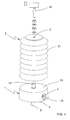
- Fig. 1, a front top perspective view, exploded, of a coupling device according to the invention, in which the two blocks making up the device are separate with one facing the other to be coupled;
- Fig. 2, a similar view to Fig. 1, according to a front bottom view;
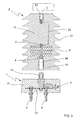
- Fig. 3, a sectional view of the device in the preceding figures;
- Fig. 4, a similar view to Fig. 3, representing an electrical diagram of the components of the first block.
- The embodiment shown in Figs. 1 through 4 corresponds to a coupling device intended to couple a data transmission equipment to one of the phases of a three-phase electrical power line. In this particular example, the nominal voltage between phases in the power line is 24 kV and the range of frequencies (bandwidth) of the data transmission signal is between 2 MHz and 38 MHz.
- The coupling device is made up of two
blocks - The
first block 1 has a substantially cylindrical shape and comprises protection, tuning and adaptation means 9, connection means 4 to said data transmission equipment and structure attachment means 5, with the latter also being ground connection means. Protection, tuning and adaptation means 9 are made up of adrain coil 24, agas discharger 25 and atuning circuit 28 arranged on the line connection side and coupled by means of aninsulation transformer 27 on the data transmission equipment side, where agas discharger 26 is also arranged, all according to the electrical diagram shown in Fig. 4. Saidfirst block 1 is provided with a threaded,metallic shank 13 that projects in the central position from thetop surface 15 of saidfirst block 1 and which, together with a threadedhole 14 in ametallic bushing 19 housed in thesecond block 2, forms, as will be seen later, electrical connection and mechanical coupling means between the twoblocks BNC type connector 4 housed in arecess 18 arranged on the side wall of saidfirst block 1. Thetuning circuit 28 is arranged on a printedcircuit board 12 that is attached to the heads of threemetallic bolts 5. The shanks of thesebolts 5 project from thelower seating surface 17 of thefirst block 1 and its heads are in contact with the parts of said protection, tuning and adaptation means 9 that must have a ground connection, according to the electrical diagram in Fig. 4, so that thesebolts 5 form simultaneously structure attachment means and ground connection means. On the other hand, the inner end ofshank 13 is threaded in a housing in the printedcircuit board 12 where it is connected to protection, tuning and adaptation means 9 according to the electrical diagram in Fig. 4. - This
first block 1 is formed in anencapsulation 10 of epoxy resin with hardener fillers and coloring agent, with this resin being of the type that is cold molded. Therefore, the various components of thefirst block 1 are connected according to the arrangement shown in Fig. 3 and they are placed in a cylindrical shaped mould, where the space ofrecess 18 is preserved. A cold mixture of said epoxy resin with hardener fillers is cast in said mould, said mixture falling directly onto the printedcircuit board 12 that does not have any protection. After the setting process, the next step is stripping the mould and, after a series of finishing operations which basically consist in removing excess material, saidfirst block 1 is obtained in which only the shanks ofbolts 5, the BNC typesingle connector 4 and the threadedshank 13 are accessible. - The
second block 2 comprises acoupling capacitor 6, which in this particular example has a capacity of 2 nF. Thefirst end 7 of saidcapacitor 6 is connected, by arigid cable 23, to ametallic bushing 20 provided with a threadedhole 3 in the top surface of saidsecond block 2 and which constitutes connection means to a phase of a power line. This connection can be made by threading in hole 3 astud 22 with the corresponding locknuts for attaching to a line connection cable. Thesecond end 8 ofcapacitor 6 is connected via screws to ametallic bushing 19 provided with a threadedhole 14 in the central position oflower surface 16 of saidsecond block 2. The threadedhole 14 and the threadedshank 13 are complementary. The shapes of the top 15 and bottom 16 surfaces ofblocks second block 2 is thus coupled to thefirst block 1 by threadingshank 13 into threadedhole 14 until the twosurfaces - This
second block 2 is formed in anencapsulation 11 of epoxy resin with hardener, fillers, silica and coloring agent, with this resin being of the hot injection type. Therefore, thecapacitor 6 is placed in a hot injection mould connected tobushings second block 2 is obtained in which only threadedholes second block 2, made up of a series of concentric,truncated bell elements 21 whose function is to increase the creepage distance, so that thisencapsulation 11 also forms suitable insulation against line surges.
Claims (13)
- Capacitive coupling device of data transmission equipment to a phase of an electrical power line in order to transmit, over said power line, an electrical data signal in a range of frequencies between 3 kHz and 100 MHz, with said coupling device being of the type that comprises at least the following components:- line connection means (3), equipment connection means (4) and ground connection means (5), whereby said coupling device is suitable for connecting respectively to said phase of a power line, to said data transmission equipment and to the ground;- a coupling capacitor (6) connected at its first end (7) to said line connection means (3) and at its second end (8), directly or via a protection device, to said ground connection means (5); and- protection, tuning and adaptation means (9) which form an interface between said second end (8) of said coupling capacitor (6) and said equipment connection means (4),said coupling device being characterized in that it is made up of two blocks (1, 2) that can be coupled together mechanically to form a compact unit:- a first block (1) that comprises said protection, tuning and adaptation means (9), said ground connection means (5), said equipment connection means (4) and structure attachment means (5), and- a second block (2) that comprises said coupling capacitor (6) and said line connection means (3),said first (1) and second (2) blocks being provided with mutual electrical connection means (13, 14) and mutual mechanical coupling means (13, 14).
- Coupling device according to claim 1, characterized in that said first (1) and second (2) blocks are each made up of a molded resin encapsulation (10, 11), where said encapsulations (10, 11) only leave accessible said ground connection (5), said equipment connection means (4), said structure attachment means (5) means, said line connection means (3), said mutual electrical connection means (13, 14) and said mutual mechanical coupling means (13, 14).
- Coupling device according to claim 2, characterized in that said first block (1) comprises a printed circuit board (12) that houses at least one part of said protection, tuning and adaptation means (9), with the resin forming said encapsulation (10) of the first block (1) being one that is suitable for cold molding and said resin being applied in direct contact with said printed circuit board (12).
- Coupling device according to claims 2 or 3, characterized in that the encapsulation (11) of said second block (2) has an external shape in the form of a cylindrical or conical housing made up of a series of concentric, truncated bell elements (21).
- Coupling device according to claim 4, characterized in that said encapsulation (10) of said first block (1) has a cylindrical or conical external shape with a lower seating surface (17) that contains said structure attachment means (5).
- Coupling device according to any of the claims 1 through 5, characterized in that said mechanical coupling means (13, 14) between said first (1) and second (2) blocks are made from an electrically conductive material and also form said mutual electrical connection means (13, 14).
- Coupling device according to claim 6, characterized in that said mechanical coupling means between said first (1) and second (2) blocks, which also form said mutual electrical connection means, are made up, on the one hand, of a threaded shank (13) made from electrically conductive material integral with said first block (1) and connected electrically to said protection, tuning and adaptation means (9) and, on the other hand, of a threaded hole (14) in a bushing (19) made from electrically conductive material and that is in said second block (2) and connected to the second end (8) of said coupling capacitor (6), said threaded shank (13) and said threaded hole (14) being complementary.
- Device according to claim 7, characterized in that said first block (1) has a top surface (15) in the center of which said threaded shank (13) is arranged, and said second block (2) has a bottom surface (16), complementary to said top surface (15), in the center of which said threaded hole is arranged (14).
- Coupling device according to any of the claims 1 through 8, characterized in that said structure attachment means (5) consist of a mechanical attachment device made from electrically conductive material and which also forms said ground connection means (5).
- Device according to claims 3, 5 and 9, characterized in that said mechanical attachment means consist of a plurality of bolts (5) the shanks of which project from said lower seating surface (17) and the heads of which are applied on to said printed circuit board (12) in contact with the parts of said protection, tuning and adaptation means (9) that must have a ground connection.
- Coupling device according to any of the claims 1 through 10, characterized in that said equipment attachment means (4) consist of a single connector housed in a recess (18) in said first block (1).
- Device according to any of the claims 1 through 11, characterized in that said line connection means (3) consist of a threaded hole in a bushing (20) made from electrically conductive material that is housed in said second block (2) and connected to the first end (7) of said coupling capacitor (6).
- Coupling device according to any of the claims 1 through 12, characterized in that said coupling capacitor (6) has a capacity greater or equal to 0.1 nF and lower or equal to 5 nF, with said coupling device being suitable for connecting to a phase of an electrical power line whose voltage between phase and neutral is greater or equivalent to 5 kV.
Applications Claiming Priority (2)
| Application Number | Priority Date | Filing Date | Title |
|---|---|---|---|
| ES200401794A ES2216732B1 (en) | 2004-07-22 | 2004-07-22 | "CAPACITIVE COUPLING DEVICE OF A DATA TRANSMISSION EQUIPMENT TO A PHASE OF A POWER LINE." |
| PCT/ES2005/000389 WO2006035078A1 (en) | 2004-07-22 | 2005-07-07 | Device for the capacitive coupling of a data-transmission device to a phase of an electrical power line |
Publications (3)
| Publication Number | Publication Date |
|---|---|
| EP1770871A1 true EP1770871A1 (en) | 2007-04-04 |
| EP1770871A4 EP1770871A4 (en) | 2012-01-04 |
| EP1770871B1 EP1770871B1 (en) | 2017-08-23 |
Family
ID=33186414
Family Applications (1)
| Application Number | Title | Priority Date | Filing Date |
|---|---|---|---|
| EP05773887.4A Expired - Lifetime EP1770871B1 (en) | 2004-07-22 | 2005-07-07 | Device for the capacitive coupling of a data-transmission device to a phase of an electrical power line |
Country Status (4)
| Country | Link |
|---|---|
| EP (1) | EP1770871B1 (en) |
| ES (2) | ES2216732B1 (en) |
| PT (1) | PT1770871T (en) |
| WO (1) | WO2006035078A1 (en) |
Cited By (3)
| Publication number | Priority date | Publication date | Assignee | Title |
|---|---|---|---|---|
| EP2757705A1 (en) * | 2013-01-22 | 2014-07-23 | ABB Technology AG | Medium voltage power line communication coupler |
| EP2871484A1 (en) * | 2013-11-07 | 2015-05-13 | Power Plus Communications AG | Coupler, coupling module and coupler system for the connection of measuring and/or communication means to a power distribution network |
| DE102014225748A1 (en) * | 2014-12-12 | 2016-06-30 | Power Plus Communications Ag | Connection adapter for a high-voltage component and a high-voltage module |
Families Citing this family (2)
| Publication number | Priority date | Publication date | Assignee | Title |
|---|---|---|---|---|
| ES2263353B2 (en) * | 2004-10-28 | 2007-10-01 | Union Fenosa Distribucion, S.A. | COUPLING DEVICE OF COMMUNICATIONS BEARING SIGNAL IN AN ELECTRICAL NETWORK. |
| ES2233218B1 (en) * | 2005-02-16 | 2006-08-01 | Distribuidora Industrial De Automatismos Y Teletransmision S.A. (Dimat S.A.) | INDUCTIVE COUPLING DEVICE OF A DATA TRANSMISSION EQUIPMENT TO A PHASE OF A POWER LINE, AND CORRESPONDING MANUFACTURING PROCEDURE. |
Family Cites Families (10)
| Publication number | Priority date | Publication date | Assignee | Title |
|---|---|---|---|---|
| GB249630A (en) * | 1925-01-27 | 1926-04-01 | Electrical Improvements Ltd | Improvements in or relating to wired wireless systems |
| GB635014A (en) * | 1947-05-27 | 1950-03-29 | Gen Electric Co Ltd | Improvements in and relating to filters for coupling carrier transmission equipment to power lines |
| JPH08264330A (en) * | 1995-03-24 | 1996-10-11 | Takaoka Electric Mfg Co Ltd | High voltage coupler |
| DE19907095C5 (en) * | 1999-02-19 | 2004-01-15 | Siemens Ag | Circuit for capacitive coupling of a data transmission device to an energy transmission network, and coupling unit with coupling circuit |
| DE50013593D1 (en) * | 1999-08-18 | 2006-11-23 | Siemens Ag | Coupling unit with integrated plug contact area for coupling a data transmission device to the phase of an electrical power transmission network |
| US6683531B2 (en) * | 2000-05-04 | 2004-01-27 | Trench Limited | Coupling device for providing a communications link for RF broadband data signals to a power line and method for installing same |
| DE10044638A1 (en) * | 2000-09-08 | 2002-04-04 | Pfisterer Kontaktsyst Gmbh | Device for electrically connecting a data connection line to a low-voltage power supply line |
| ATE304242T1 (en) * | 2001-10-31 | 2005-09-15 | Power Plus Communications Ag | COUPLING UNIT WITH INTEGRATED PLUG CONTACT AREA |
| WO2003107560A1 (en) * | 2002-06-12 | 2003-12-24 | Grupo Ormazabal, S.A. | Medium-voltage isolated capacitive coupling system |
| US6753742B2 (en) * | 2002-08-13 | 2004-06-22 | Korea Electro Technology Research Institute | Signal coupling apparatus for communication by medium voltage power line |
-
2004
- 2004-07-22 ES ES200401794A patent/ES2216732B1/en not_active Expired - Fee Related
-
2005
- 2005-07-07 WO PCT/ES2005/000389 patent/WO2006035078A1/en not_active Ceased
- 2005-07-07 ES ES05773887.4T patent/ES2647093T3/en not_active Expired - Lifetime
- 2005-07-07 EP EP05773887.4A patent/EP1770871B1/en not_active Expired - Lifetime
- 2005-07-07 PT PT57738874T patent/PT1770871T/en unknown
Cited By (4)
| Publication number | Priority date | Publication date | Assignee | Title |
|---|---|---|---|---|
| EP2757705A1 (en) * | 2013-01-22 | 2014-07-23 | ABB Technology AG | Medium voltage power line communication coupler |
| EP2871484A1 (en) * | 2013-11-07 | 2015-05-13 | Power Plus Communications AG | Coupler, coupling module and coupler system for the connection of measuring and/or communication means to a power distribution network |
| DE102014225748A1 (en) * | 2014-12-12 | 2016-06-30 | Power Plus Communications Ag | Connection adapter for a high-voltage component and a high-voltage module |
| DE102014225748B4 (en) | 2014-12-12 | 2018-05-09 | Power Plus Communications Ag | Connection adapter for a high-voltage component and a high-voltage module |
Also Published As
| Publication number | Publication date |
|---|---|
| ES2216732B1 (en) | 2005-07-16 |
| EP1770871A4 (en) | 2012-01-04 |
| EP1770871B1 (en) | 2017-08-23 |
| WO2006035078A1 (en) | 2006-04-06 |
| ES2647093T3 (en) | 2017-12-19 |
| PT1770871T (en) | 2017-11-21 |
| ES2216732A1 (en) | 2004-10-16 |
Similar Documents
| Publication | Publication Date | Title |
|---|---|---|
| US6476520B1 (en) | Plug connection | |
| US6066801A (en) | Cable television/telephone tap | |
| US3617811A (en) | Cable television tapoff unit | |
| CA2160854A1 (en) | Top exit coupler | |
| WO1999048224A1 (en) | Telecommunications signal coupler apparatus and method | |
| EP2605416B1 (en) | High-voltage coupling device | |
| EP1770871B1 (en) | Device for the capacitive coupling of a data-transmission device to a phase of an electrical power line | |
| JP2014523619A (en) | Cable part and communication equipment for connection of subscriber line to data bus line | |
| US5505636A (en) | CATV power tapping device | |
| JPH0238524Y2 (en) | ||
| JPH0689757A (en) | Electric connector | |
| EP1521381A1 (en) | Medium-voltage isolated capacitive coupling system | |
| AU711308B2 (en) | Top exit coupler | |
| FI80176C (en) | HUSFOERDELNINGSNAET FOER ENKLA OCH CENTRALANTENNER. | |
| US20020145840A1 (en) | Cable network interface circuit | |
| WO1996019852A1 (en) | High-frequency signal branching device | |
| EP0205563B1 (en) | System for selectively coupling a plurality of data stations into a single communications path | |
| JP2020005164A (en) | PLC adapter and power line communication system using the same | |
| CN103855478A (en) | F-Connector with Integrated Surge Protection | |
| EP4510606A1 (en) | Improvements in or relating to signal tap faceplate alignment | |
| EP3174167B1 (en) | Coaxial cable extender | |
| JPH10509288A (en) | CATV tap | |
| JPS6343808Y2 (en) | ||
| JPS6324687Y2 (en) | ||
| AU2023241283A1 (en) | Face plate for cable tap unit |
Legal Events
| Date | Code | Title | Description |
|---|---|---|---|
| PUAI | Public reference made under article 153(3) epc to a published international application that has entered the european phase |
Free format text: ORIGINAL CODE: 0009012 |
|
| 17P | Request for examination filed |
Effective date: 20070117 |
|
| AK | Designated contracting states |
Kind code of ref document: A1 Designated state(s): AT BE BG CH CY CZ DE DK EE ES FI FR GB GR HU IE IS IT LI LT LU LV MC NL PL PT RO SE SI SK TR |
|
| XX | Miscellaneous (additional remarks) |
Free format text: A REQUEST FOR CORRECTION OF THE DRAWINGS UNDER RULE 88 HAS BEEN FILED. A DECISION WILL BE TAKEN DURING EXAMINATION PROCEEDINGS. |
|
| DAX | Request for extension of the european patent (deleted) | ||
| A4 | Supplementary search report drawn up and despatched |
Effective date: 20111202 |
|
| RIC1 | Information provided on ipc code assigned before grant |
Ipc: H04B 3/56 20060101AFI20111128BHEP |
|
| RAP1 | Party data changed (applicant data changed or rights of an application transferred) |
Owner name: ZIV COMMUNICATIONS S.A. |
|
| GRAP | Despatch of communication of intention to grant a patent |
Free format text: ORIGINAL CODE: EPIDOSNIGR1 |
|
| STAA | Information on the status of an ep patent application or granted ep patent |
Free format text: STATUS: GRANT OF PATENT IS INTENDED |
|
| INTG | Intention to grant announced |
Effective date: 20170213 |
|
| GRAS | Grant fee paid |
Free format text: ORIGINAL CODE: EPIDOSNIGR3 |
|
| GRAA | (expected) grant |
Free format text: ORIGINAL CODE: 0009210 |
|
| STAA | Information on the status of an ep patent application or granted ep patent |
Free format text: STATUS: THE PATENT HAS BEEN GRANTED |
|
| AK | Designated contracting states |
Kind code of ref document: B1 Designated state(s): AT BE BG CH CY CZ DE DK EE ES FI FR GB GR HU IE IS IT LI LT LU LV MC NL PL PT RO SE SI SK TR |
|
| REG | Reference to a national code |
Ref country code: GB Ref legal event code: FG4D |
|
| XX | Miscellaneous (additional remarks) |
Free format text: A REQUEST FOR CORRECTION OF THE DRAWINGS UNDER RULE 88 HAS BEEN FILED. A DECISION WILL BE TAKEN DURING EXAMINATION PROCEEDINGS. |
|
| REG | Reference to a national code |
Ref country code: CH Ref legal event code: EP |
|
| REG | Reference to a national code |
Ref country code: AT Ref legal event code: REF Ref document number: 922336 Country of ref document: AT Kind code of ref document: T Effective date: 20170915 |
|
| REG | Reference to a national code |
Ref country code: IE Ref legal event code: FG4D |
|
| REG | Reference to a national code |
Ref country code: DE Ref legal event code: R096 Ref document number: 602005052592 Country of ref document: DE |
|
| REG | Reference to a national code |
Ref country code: PT Ref legal event code: SC4A Ref document number: 1770871 Country of ref document: PT Date of ref document: 20171121 Kind code of ref document: T Free format text: AVAILABILITY OF NATIONAL TRANSLATION Effective date: 20171114 |
|
| REG | Reference to a national code |
Ref country code: NL Ref legal event code: FP |
|
| REG | Reference to a national code |
Ref country code: ES Ref legal event code: FG2A Ref document number: 2647093 Country of ref document: ES Kind code of ref document: T3 Effective date: 20171219 |
|
| REG | Reference to a national code |
Ref country code: LT Ref legal event code: MG4D |
|
| REG | Reference to a national code |
Ref country code: AT Ref legal event code: MK05 Ref document number: 922336 Country of ref document: AT Kind code of ref document: T Effective date: 20170823 |
|
| PG25 | Lapsed in a contracting state [announced via postgrant information from national office to epo] |
Ref country code: AT Free format text: LAPSE BECAUSE OF FAILURE TO SUBMIT A TRANSLATION OF THE DESCRIPTION OR TO PAY THE FEE WITHIN THE PRESCRIBED TIME-LIMIT Effective date: 20170823 Ref country code: SE Free format text: LAPSE BECAUSE OF FAILURE TO SUBMIT A TRANSLATION OF THE DESCRIPTION OR TO PAY THE FEE WITHIN THE PRESCRIBED TIME-LIMIT Effective date: 20170823 Ref country code: FI Free format text: LAPSE BECAUSE OF FAILURE TO SUBMIT A TRANSLATION OF THE DESCRIPTION OR TO PAY THE FEE WITHIN THE PRESCRIBED TIME-LIMIT Effective date: 20170823 Ref country code: LT Free format text: LAPSE BECAUSE OF FAILURE TO SUBMIT A TRANSLATION OF THE DESCRIPTION OR TO PAY THE FEE WITHIN THE PRESCRIBED TIME-LIMIT Effective date: 20170823 |
|
| PG25 | Lapsed in a contracting state [announced via postgrant information from national office to epo] |
Ref country code: LV Free format text: LAPSE BECAUSE OF FAILURE TO SUBMIT A TRANSLATION OF THE DESCRIPTION OR TO PAY THE FEE WITHIN THE PRESCRIBED TIME-LIMIT Effective date: 20170823 Ref country code: IS Free format text: LAPSE BECAUSE OF FAILURE TO SUBMIT A TRANSLATION OF THE DESCRIPTION OR TO PAY THE FEE WITHIN THE PRESCRIBED TIME-LIMIT Effective date: 20171223 Ref country code: PL Free format text: LAPSE BECAUSE OF FAILURE TO SUBMIT A TRANSLATION OF THE DESCRIPTION OR TO PAY THE FEE WITHIN THE PRESCRIBED TIME-LIMIT Effective date: 20170823 Ref country code: GR Free format text: LAPSE BECAUSE OF FAILURE TO SUBMIT A TRANSLATION OF THE DESCRIPTION OR TO PAY THE FEE WITHIN THE PRESCRIBED TIME-LIMIT Effective date: 20171124 Ref country code: BG Free format text: LAPSE BECAUSE OF FAILURE TO SUBMIT A TRANSLATION OF THE DESCRIPTION OR TO PAY THE FEE WITHIN THE PRESCRIBED TIME-LIMIT Effective date: 20171123 |
|
| PG25 | Lapsed in a contracting state [announced via postgrant information from national office to epo] |
Ref country code: DK Free format text: LAPSE BECAUSE OF FAILURE TO SUBMIT A TRANSLATION OF THE DESCRIPTION OR TO PAY THE FEE WITHIN THE PRESCRIBED TIME-LIMIT Effective date: 20170823 Ref country code: CZ Free format text: LAPSE BECAUSE OF FAILURE TO SUBMIT A TRANSLATION OF THE DESCRIPTION OR TO PAY THE FEE WITHIN THE PRESCRIBED TIME-LIMIT Effective date: 20170823 Ref country code: RO Free format text: LAPSE BECAUSE OF FAILURE TO SUBMIT A TRANSLATION OF THE DESCRIPTION OR TO PAY THE FEE WITHIN THE PRESCRIBED TIME-LIMIT Effective date: 20170823 |
|
| REG | Reference to a national code |
Ref country code: DE Ref legal event code: R097 Ref document number: 602005052592 Country of ref document: DE |
|
| PG25 | Lapsed in a contracting state [announced via postgrant information from national office to epo] |
Ref country code: SK Free format text: LAPSE BECAUSE OF FAILURE TO SUBMIT A TRANSLATION OF THE DESCRIPTION OR TO PAY THE FEE WITHIN THE PRESCRIBED TIME-LIMIT Effective date: 20170823 Ref country code: EE Free format text: LAPSE BECAUSE OF FAILURE TO SUBMIT A TRANSLATION OF THE DESCRIPTION OR TO PAY THE FEE WITHIN THE PRESCRIBED TIME-LIMIT Effective date: 20170823 |
|
| REG | Reference to a national code |
Ref country code: FR Ref legal event code: PLFP Year of fee payment: 14 |
|
| PLBE | No opposition filed within time limit |
Free format text: ORIGINAL CODE: 0009261 |
|
| STAA | Information on the status of an ep patent application or granted ep patent |
Free format text: STATUS: NO OPPOSITION FILED WITHIN TIME LIMIT |
|
| 26N | No opposition filed |
Effective date: 20180524 |
|
| PG25 | Lapsed in a contracting state [announced via postgrant information from national office to epo] |
Ref country code: SI Free format text: LAPSE BECAUSE OF FAILURE TO SUBMIT A TRANSLATION OF THE DESCRIPTION OR TO PAY THE FEE WITHIN THE PRESCRIBED TIME-LIMIT Effective date: 20170823 |
|
| REG | Reference to a national code |
Ref country code: CH Ref legal event code: PL |
|
| PG25 | Lapsed in a contracting state [announced via postgrant information from national office to epo] |
Ref country code: LU Free format text: LAPSE BECAUSE OF NON-PAYMENT OF DUE FEES Effective date: 20180707 Ref country code: MC Free format text: LAPSE BECAUSE OF FAILURE TO SUBMIT A TRANSLATION OF THE DESCRIPTION OR TO PAY THE FEE WITHIN THE PRESCRIBED TIME-LIMIT Effective date: 20170823 |
|
| REG | Reference to a national code |
Ref country code: BE Ref legal event code: MM Effective date: 20180731 |
|
| REG | Reference to a national code |
Ref country code: IE Ref legal event code: MM4A |
|
| PG25 | Lapsed in a contracting state [announced via postgrant information from national office to epo] |
Ref country code: LI Free format text: LAPSE BECAUSE OF NON-PAYMENT OF DUE FEES Effective date: 20180731 Ref country code: CH Free format text: LAPSE BECAUSE OF NON-PAYMENT OF DUE FEES Effective date: 20180731 Ref country code: IE Free format text: LAPSE BECAUSE OF NON-PAYMENT OF DUE FEES Effective date: 20180707 |
|
| PG25 | Lapsed in a contracting state [announced via postgrant information from national office to epo] |
Ref country code: BE Free format text: LAPSE BECAUSE OF NON-PAYMENT OF DUE FEES Effective date: 20180731 |
|
| PG25 | Lapsed in a contracting state [announced via postgrant information from national office to epo] |
Ref country code: TR Free format text: LAPSE BECAUSE OF FAILURE TO SUBMIT A TRANSLATION OF THE DESCRIPTION OR TO PAY THE FEE WITHIN THE PRESCRIBED TIME-LIMIT Effective date: 20170823 |
|
| PG25 | Lapsed in a contracting state [announced via postgrant information from national office to epo] |
Ref country code: HU Free format text: LAPSE BECAUSE OF FAILURE TO SUBMIT A TRANSLATION OF THE DESCRIPTION OR TO PAY THE FEE WITHIN THE PRESCRIBED TIME-LIMIT; INVALID AB INITIO Effective date: 20050707 |
|
| PG25 | Lapsed in a contracting state [announced via postgrant information from national office to epo] |
Ref country code: CY Free format text: LAPSE BECAUSE OF FAILURE TO SUBMIT A TRANSLATION OF THE DESCRIPTION OR TO PAY THE FEE WITHIN THE PRESCRIBED TIME-LIMIT Effective date: 20170823 |
|
| PGFP | Annual fee paid to national office [announced via postgrant information from national office to epo] |
Ref country code: PT Payment date: 20220620 Year of fee payment: 18 Ref country code: NL Payment date: 20220630 Year of fee payment: 18 Ref country code: IT Payment date: 20220628 Year of fee payment: 18 Ref country code: GB Payment date: 20220623 Year of fee payment: 18 |
|
| PGFP | Annual fee paid to national office [announced via postgrant information from national office to epo] |
Ref country code: FR Payment date: 20220623 Year of fee payment: 18 |
|
| PGFP | Annual fee paid to national office [announced via postgrant information from national office to epo] |
Ref country code: ES Payment date: 20220801 Year of fee payment: 18 Ref country code: DE Payment date: 20220531 Year of fee payment: 18 |
|
| REG | Reference to a national code |
Ref country code: DE Ref legal event code: R119 Ref document number: 602005052592 Country of ref document: DE |
|
| REG | Reference to a national code |
Ref country code: NL Ref legal event code: MM Effective date: 20230801 |
|
| GBPC | Gb: european patent ceased through non-payment of renewal fee |
Effective date: 20230707 |
|
| PG25 | Lapsed in a contracting state [announced via postgrant information from national office to epo] |
Ref country code: NL Free format text: LAPSE BECAUSE OF NON-PAYMENT OF DUE FEES Effective date: 20230801 |
|
| PG25 | Lapsed in a contracting state [announced via postgrant information from national office to epo] |
Ref country code: NL Free format text: LAPSE BECAUSE OF NON-PAYMENT OF DUE FEES Effective date: 20230801 Ref country code: DE Free format text: LAPSE BECAUSE OF NON-PAYMENT OF DUE FEES Effective date: 20240201 Ref country code: PT Free format text: LAPSE BECAUSE OF NON-PAYMENT OF DUE FEES Effective date: 20240108 Ref country code: GB Free format text: LAPSE BECAUSE OF NON-PAYMENT OF DUE FEES Effective date: 20230707 |
|
| PG25 | Lapsed in a contracting state [announced via postgrant information from national office to epo] |
Ref country code: FR Free format text: LAPSE BECAUSE OF NON-PAYMENT OF DUE FEES Effective date: 20230731 |
|
| PG25 | Lapsed in a contracting state [announced via postgrant information from national office to epo] |
Ref country code: IT Free format text: LAPSE BECAUSE OF NON-PAYMENT OF DUE FEES Effective date: 20230707 |
|
| REG | Reference to a national code |
Ref country code: ES Ref legal event code: FD2A Effective date: 20240827 |
|
| PG25 | Lapsed in a contracting state [announced via postgrant information from national office to epo] |
Ref country code: ES Free format text: LAPSE BECAUSE OF NON-PAYMENT OF DUE FEES Effective date: 20230708 |
|
| PG25 | Lapsed in a contracting state [announced via postgrant information from national office to epo] |
Ref country code: ES Free format text: LAPSE BECAUSE OF NON-PAYMENT OF DUE FEES Effective date: 20230708 |