EP1770468A1 - Apparatus and method for removing undesired signals in instrument landing systems - Google Patents
Apparatus and method for removing undesired signals in instrument landing systems Download PDFInfo
- Publication number
- EP1770468A1 EP1770468A1 EP06121283A EP06121283A EP1770468A1 EP 1770468 A1 EP1770468 A1 EP 1770468A1 EP 06121283 A EP06121283 A EP 06121283A EP 06121283 A EP06121283 A EP 06121283A EP 1770468 A1 EP1770468 A1 EP 1770468A1
- Authority
- EP
- European Patent Office
- Prior art keywords
- signals
- undesired
- modulation
- frequency
- undesired signals
- Prior art date
- Legal status (The legal status is an assumption and is not a legal conclusion. Google has not performed a legal analysis and makes no representation as to the accuracy of the status listed.)
- Withdrawn
Links
- 238000000034 method Methods 0.000 title claims abstract description 20
- 230000001360 synchronised effect Effects 0.000 claims abstract description 21
- 238000013459 approach Methods 0.000 description 10
- 230000000694 effects Effects 0.000 description 9
- 238000001914 filtration Methods 0.000 description 4
- 230000005855 radiation Effects 0.000 description 4
- 230000005540 biological transmission Effects 0.000 description 3
- 238000012986 modification Methods 0.000 description 2
- 230000004048 modification Effects 0.000 description 2
- 230000000052 comparative effect Effects 0.000 description 1
- 238000010586 diagram Methods 0.000 description 1
- 230000000717 retained effect Effects 0.000 description 1
Images

Classifications
-
- G—PHYSICS
- G01—MEASURING; TESTING
- G01S—RADIO DIRECTION-FINDING; RADIO NAVIGATION; DETERMINING DISTANCE OR VELOCITY BY USE OF RADIO WAVES; LOCATING OR PRESENCE-DETECTING BY USE OF THE REFLECTION OR RERADIATION OF RADIO WAVES; ANALOGOUS ARRANGEMENTS USING OTHER WAVES
- G01S1/00—Beacons or beacon systems transmitting signals having a characteristic or characteristics capable of being detected by non-directional receivers and defining directions, positions, or position lines fixed relatively to the beacon transmitters; Receivers co-operating therewith
- G01S1/02—Beacons or beacon systems transmitting signals having a characteristic or characteristics capable of being detected by non-directional receivers and defining directions, positions, or position lines fixed relatively to the beacon transmitters; Receivers co-operating therewith using radio waves
- G01S1/08—Systems for determining direction or position line
- G01S1/14—Systems for determining direction or position line using amplitude comparison of signals transmitted simultaneously from antennas or antenna systems having differently oriented overlapping directivity-characteristics
-
- G—PHYSICS
- G01—MEASURING; TESTING
- G01S—RADIO DIRECTION-FINDING; RADIO NAVIGATION; DETERMINING DISTANCE OR VELOCITY BY USE OF RADIO WAVES; LOCATING OR PRESENCE-DETECTING BY USE OF THE REFLECTION OR RERADIATION OF RADIO WAVES; ANALOGOUS ARRANGEMENTS USING OTHER WAVES
- G01S1/00—Beacons or beacon systems transmitting signals having a characteristic or characteristics capable of being detected by non-directional receivers and defining directions, positions, or position lines fixed relatively to the beacon transmitters; Receivers co-operating therewith
- G01S1/02—Beacons or beacon systems transmitting signals having a characteristic or characteristics capable of being detected by non-directional receivers and defining directions, positions, or position lines fixed relatively to the beacon transmitters; Receivers co-operating therewith using radio waves
- G01S1/04—Details
- G01S1/045—Receivers
Definitions
- the present invention generally relates to aviation guidance systems and methods for removing undesired signals in aviation guidance systems. More particularly, the invention relates to systems and methods for minimizing localizer and glideslope errors in aviation guidance systems.
- An instrument landing system is a ground-based transmission system that provides runway approach information to aircraft.
- Some conventional systems comprise a localizer subsystem and a glide slope subsystem.
- the localizer subsystem provides lateral guidance to aircraft for tracking the runway centerline.
- the glide slope subsystem provides vertical guidance to aircraft for descending at the proper glide path.
- Conventional localizer subsystems include a localizer antenna array that radiates a signal comprising an RF carrier amplitude modulated with equal amplitudes of 90 Hz and 150 Hz tones.
- the localizer receiver resides with the aircraft.
- the localizer radiation patterns are normally arranged such that the 90 Hz and 150 Hz tones will have equal levels when the receiving aircraft is on the runway centerline and extention thereof.
- conventional glide slope subsystems include a glide slope antenna array that radiates a signal comprising an RF carrier amplitude modulated with equal amplitudes of 90 Hz and 150 Hz tones,
- the glide slope resides with the aircraft.
- the glide slope radiation patterns are normally arranged such that the 90 Hz and 150 Hz tones will have equal levels when the receiving aircraft is descending at the desired glide path angle, which is typically referenced at three degrees.
- some conventional instrument landing systems including conventional localizer and glide slope systems, may be implemented on aircraft that generate propeller or rotor modulation effects and/or observe multipath effects, which can introduce errors into the ILS.
- errors may be introduced when the propeller or rotor modulation frequency or the multipath frequency is approximately 90 Hz or 150 Hz (i.e., the same as either one of the localizer and glide slope tones of the ILS) or a subharmonic of 90 Hz or 150 Hz (e.g., 15, 30, 37.5, 45, or 75 Hz). Such errors can cause the aircraft to oscillate or fly an offset course.
- an instrument landing system capable of removing undesired modulation effects such as, for example, propeller or rotor modulation effects.
- a method of removing undesired signals in an aviation guidance system may comprise receiving at least one first desired signal having a first frequency of amplitude modulation, receiving at least one second desired signal having a second frequency of amplitude modulation, and receiving at least one undesired signal having any frequency including a frequency that is substantially the same as or a subharmonic of at least one of the first and second desired signals.
- the first and second frequencies of amplitude modulation are phase synchronous, and the undesired signals are non-synchronous with at least one of the first and second desired signals,
- the method may also include identifying the undesired signals and removing the undesired signals,
- an aviation guidance system may comprise at least one receiver configured to receive at least one first desired signal having a first frequency of amplitude modulation and at least one second desired signal having a second frequency modulation.
- the first and second frequencies of amplitude modulation are phase synchronous.
- the system may further comprise a controller configured to identify and remove undesired signals received by the receiver.
- the undesired signals may have any frequency including frequencies that are substantially the same as or subharmonics of at least one of the first and second desired signals, but are non-synchronous with at least one of the first and second desired signals.
- a method of minimizing localizer and glide slope errors in an aviation guidance system may comprise receiving at least one first desired signal having a first frequency of amplitude modulation, receiving at least one second desired signal having a second frequency of amplitude modulation, and receiving undesired signals having any frequency including frequencies that are substantially the same as or subharmonics of at least one of the first and second desired signals.
- the first and second desired signals may represent at least one of localizer information and glide slope information for an aircraft.
- the first and second frequencies of amplitude mediation are phase synchronous, but the undesired signals are non-synchronous with at least one of the first and second desired signals.
- the undesired signals may include propeller modulation, rotor modulation, and/or multipath.
- the method may further comprise comparing amplitude and phase of the first and second desired signals and the at least one undesired signal, determining which of the desired and undesired signals are non-synchronous, and removing the undesired signals.
- FIG. 1 is a block diagram of an exemplary system for removing undesired signals in instrument landing systems in accordance with various aspects of the disclosure.
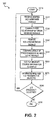
- FIG. 2 is a flow chart of an exemplary method for removing undesired signals in instrument landing systems in accordance with various aspects of the disclosure.
- FIG. 1 illustrates an exemplary aviation guidance system 100 in accordance with various aspects of the disclosure.
- the aviation guidance system 100 may comprise a portion of an instrument landing system (ILS) 10.
- the ILS 10 may comprise one or more localizer transmitters 20 at a landing site, one or more glide slope transmitters 30 at the runway landing site, and the aviation guidance system 100,
- Each of the transmitters 20, 30 may comprise a highly directional transmitting system.
- the aviation guidance system 100 may comprise a localizer receiver 120 and a glide slope receiver 130 associated with an aircraft (not shown). It should be appreciated that the localizer and glide slope receivers 120, 130 may be contained within the same physical unit or in separate units. According to various aspects, the localizer receiver 120 may be configured to receive signals from at least one localizer transmitter 20 at the landing site, and the glide slope receiver 130 may be configured to receive signals from at least one glide slope transmitter 30 at the landing site. It should be appreciated that the localizer and glide slope transmitters 20, 30 may be arranged in any configuration known to persons skilled in the art.
- the guidance system 100 may also include a controller 140 configured to process the signals received by the localizer and glide slope receivers 120, 130 and a display 150, for example, a course deviation indicator (CDI), configured to provide guidance information to a pilot, co-pilot, navigator, or the like.
- a controller 140 configured to process the signals received by the localizer and glide slope receivers 120, 130 and a display 150, for example, a course deviation indicator (CDI), configured to provide guidance information to a pilot, co-pilot, navigator, or the like.
- CDI course deviation indicator
- the localizer and glide slope transmitters 20, 30 each radiate an ILS signal modulated with two equal level, phase-locked, audio tones - a 90 Hz tone and a 150 Hz tone. Any of various known antenna radiation patterns may be used to modify the modulation of the ILS signal so that the 90 Hz and 150 Hz tones have different levels at different points in the pattern, thereby creating an approach corridor decipherable by the localizer and glide slope receivers 120, 130.
- the localizer and glide slope receivers 120, 130 may receive undesired signals having a frequency of 90 Hz or 150 Hz or a subharmonic of 90 Hz or 150 Hz such as, for example, 15, 30, 37.5,45, or 75 Hz. Such undesired signals may be caused by propeller or rotor modulation and/or by multipath effects.
- the controller 140 may be configured to remove these undesired signals.
- the controller 140 may be configured to scrutinize the phase relationship of all received signals having a frequency of 90 Hz ⁇ 2.5% and 150 Hz ⁇ 2.5%, i.e., substantially 90 Hz and 150 Hz.
- the controller 140 can identify any signals at substantially 90 Hz and/or 150 Hz that are not phase locked; that is, any signals that are non-synchronous.
- the controller 140 can then remove these undesired non-synchronous signals using any known signal processing technique such as, for example, analog notch filtering, bandpass filtering, fast Fourier transforms, or the like.
- the controller 140 can compare the levels of the 90 Hz and 150 Hz tones for both the localizer and glide slope subsystems. Based on the comparative levels of the tones, the controller 140 can determine the course of the aircraft and provide feedback to a pilot, co-pilot, navigator, or the like via the display 150.
- an exemplary method 200 for removing undesired signals in an ILS 10 may commence in step S210, Control proceeds to step 220, where the localizer and glide slope receivers 120, 130 receive desired and undesired signals.
- the desired signals include the 90 Hz and 150 Hz tones from both the localizer and glide slope transmitters 20, 30, and the undesired signals include propeller or rotor modulation effects and/or multipath effects.
- Control continues to step S230,
- step S230 controller 140 examines the phase-relationship between the desired and undesired signals and determines which signals are synchronous (i.e., phase-locked) and which are non-synchronous. Control then proceeds to step S240, where the controller 140 removes any non-synchronous signals. As described above, the phase-locked 90 Hz and 150 Hz tones from both the localizer and glide slope transmitters 20, 30 are retained and the undesired signals resulting from propeller or rotor modulation effects and/or multipath effects are removed. The undesired non-synchronous signals may be removed using any known signal processing technique such as, for example, analog notch filtering, bandpass filtering, fast Fourier transforms, or the like. Control continues to step S250.
- step S250 the controller 140 compares the levels of the phase-locked 90 Hz and 150 Hz tones received the localizer and glide slope receivers 120, 130 and determines the course of the aircraft approaching the landing site runway. Control proceeds to step S260, where the controller 140 outputs the course information to a display 150, such as a CDI. A pilot, co-pilot, navigator, or the like can interpret the information provided by the display and adjust the aircraft's course as needed. Control then continues to step S270.
- a display 150 such as a CDI.
- a pilot, co-pilot, navigator, or the like can interpret the information provided by the display and adjust the aircraft's course as needed. Control then continues to step S270.
- step S270 the controller 140 determines whether the aircraft receiver is continuing to be tuned to an ILS frequency. Then, in step S280, if the controller 140 determines that the aircraft is continuing to be tuned to an ILS frequency, control returns to step S220. Otherwise, if the controller 140 determines that the aircraft receiver is no longer being tuned to an ILS frequency (i.e., the aircraft has either landed or discontinued approach), control proceeds to step S290 and ceases.
- the localizer transmission pattern may be arranged such that the 90 Hz and 150 Hz tones will have equal levels along an extended runway centerline of the landing site.
- the controller 140 will remove undesired signals at about 90 Hz and/or 150 Hz and determine that there is no difference between the level of the desired localizer signals.
- the CDI will display no difference in the depth of modulation between the 90 Hz and 150 Hz tones. That is, the CDI needle will be centered to indicated that the aircraft is approaching the runway substantially along the centerline.
- the approach information transmitted by the ILS is in the difference of the modulation of the 90 Hz and 150 Hz tones.
- This difference is called the difference of the depth of modulation, or DDM, and is the modulation factor of one tone subtracted from the modulation factor of the other tone.
- Modulation factor is the ratio of the audio peak voltage to the RF level, and is described by the formula Va/Vc, where Va is the peak amplitude of the audio, and Vc is the amplitude of the unmodulated carrier. Percent modulation is the modulation factor multiplied by 100.
- the localizer transmitted signal has the audio modulated at 20 percent per tone.
- modulation balance This means that the 90 Hz is at a modulation factor of 0.2000 and the 150 Hz is at a modulation factor of 0.200.
- modulation balance This condition of equal modulation is called modulation balance.
- the DDM in this condition is 0.200 minus 0.200, or 0.000 DDM. In the radiation pattern, this is the condition on runway centerline.
- the controller 140 will remove undesired signals at about 90 Hz and/or 150 Hz and determine that the level of the 90 Hz tone exceeds that of the 150 Hz tone. As a result, the controller 140 will produce a deflection on the CDI to the right, indicating that the aircraft's course needs to be altered to the right. If the aircraft on approach is to the right of the runway centerline, the controller 140 will remove undesired signals at about 90 Hz and/or 150 Hz and determine that the level of the 150 Hz tone exceeds that of the 90 Hz tone. As a result, the controller 140 will produce a deflection on the CDI to the left, indicating that the aircraft's course needs to be altered to the left.
- the glide slope transmission pattern may be arranged such that the 90 Hz and 150 Hz tones will have equal levels along a desired glide path angle referenced at, for example, three degrees.
- the controller 140 will remove undesired signals at about 90 Hz and/or 150 Hz and determine that there is no difference between the level of the desired glide slope signals.
- the CDI will display no difference in the DDM between the 90 Hz and 150 Hz tones. That is, the CDI needle will be centered to indicated that the aircraft is approaching the runway substantially at the desired glide path angle.
- the controller 140 will remove undesired signals at about 90 Hz and/or 150 Hz and determine that the level of the 90 Hz tone exceeds that of the 150 Hz tone. As a result, the controller 140 will produce a downward deflection on the CDI, indicating that the aircraft's course needs to be altered in the downward direction. If the aircraft on approach is below the desired glide path angle, the controller 140 will remove undesired signals at about 90 Hz and/or 150 Hz and determine that the level of the 150 Hz tone exceeds that of the 90 Hz tone. As a result, the controller 140 will produce an upward deflection on the CDI, indicating that the aircraft's course needs to be altered in an upward direction.
- the localizer transmitter 20 may operate on one of the forty (40) ILS channels within the frequency range 108.10MHz to 111.95 MHz.
- the glide slope transmitter 30 may operate on one of the forty (40) ILS channels within the frequency range 329.15 MHz to 335 MHz, It should be appreciated that the localizer and glide slope carrier frequencies may be paired with one another so that a pilot, co-pilot, navigator, or the like has to tune only one receiver control.
Landscapes
- Engineering & Computer Science (AREA)
- Remote Sensing (AREA)
- Computer Networks & Wireless Communication (AREA)
- Physics & Mathematics (AREA)
- General Physics & Mathematics (AREA)
- Radar, Positioning & Navigation (AREA)
- Aviation & Aerospace Engineering (AREA)
- Traffic Control Systems (AREA)
- Radar Systems Or Details Thereof (AREA)
Abstract
Description
- The present invention generally relates to aviation guidance systems and methods for removing undesired signals in aviation guidance systems. More particularly, the invention relates to systems and methods for minimizing localizer and glideslope errors in aviation guidance systems.
- An instrument landing system (ILS) is a ground-based transmission system that provides runway approach information to aircraft. Some conventional systems comprise a localizer subsystem and a glide slope subsystem. The localizer subsystem provides lateral guidance to aircraft for tracking the runway centerline. The glide slope subsystem provides vertical guidance to aircraft for descending at the proper glide path.
- Conventional localizer subsystems include a localizer antenna array that radiates a signal comprising an RF carrier amplitude modulated with equal amplitudes of 90 Hz and 150 Hz tones. The localizer receiver resides with the aircraft. The localizer radiation patterns are normally arranged such that the 90 Hz and 150 Hz tones will have equal levels when the receiving aircraft is on the runway centerline and extention thereof.
- Similarly, conventional glide slope subsystems include a glide slope antenna array that radiates a signal comprising an RF carrier amplitude modulated with equal amplitudes of 90 Hz and 150 Hz tones, The glide slope resides with the aircraft. The glide slope radiation patterns are normally arranged such that the 90 Hz and 150 Hz tones will have equal levels when the receiving aircraft is descending at the desired glide path angle, which is typically referenced at three degrees.
- However, some conventional instrument landing systems, including conventional localizer and glide slope systems, may be implemented on aircraft that generate propeller or rotor modulation effects and/or observe multipath effects, which can introduce errors into the ILS. For example, errors may be introduced when the propeller or rotor modulation frequency or the multipath frequency is approximately 90 Hz or 150 Hz (i.e., the same as either one of the localizer and glide slope tones of the ILS) or a subharmonic of 90 Hz or 150 Hz (e.g., 15, 30, 37.5, 45, or 75 Hz). Such errors can cause the aircraft to oscillate or fly an offset course.
- Accordingly, it may be desirable to provide an instrument landing system capable of removing undesired modulation effects such as, for example, propeller or rotor modulation effects.
- In accordance with various aspects of the disclosure, a method of removing undesired signals in an aviation guidance system may comprise receiving at least one first desired signal having a first frequency of amplitude modulation, receiving at least one second desired signal having a second frequency of amplitude modulation, and receiving at least one undesired signal having any frequency including a frequency that is substantially the same as or a subharmonic of at least one of the first and second desired signals. The first and second frequencies of amplitude modulation are phase synchronous, and the undesired signals are non-synchronous with at least one of the first and second desired signals, The method may also include identifying the undesired signals and removing the undesired signals,
- In accordance with some aspects of the disclosure, an aviation guidance system may comprise at least one receiver configured to receive at least one first desired signal having a first frequency of amplitude modulation and at least one second desired signal having a second frequency modulation. The first and second frequencies of amplitude modulation are phase synchronous. The system may further comprise a controller configured to identify and remove undesired signals received by the receiver. The undesired signals may have any frequency including frequencies that are substantially the same as or subharmonics of at least one of the first and second desired signals, but are non-synchronous with at least one of the first and second desired signals.
- According to various aspects of the disclosure, a method of minimizing localizer and glide slope errors in an aviation guidance system may comprise receiving at least one first desired signal having a first frequency of amplitude modulation, receiving at least one second desired signal having a second frequency of amplitude modulation, and receiving undesired signals having any frequency including frequencies that are substantially the same as or subharmonics of at least one of the first and second desired signals. The first and second desired signals may represent at least one of localizer information and glide slope information for an aircraft. The first and second frequencies of amplitude mediation are phase synchronous, but the undesired signals are non-synchronous with at least one of the first and second desired signals. The undesired signals may include propeller modulation, rotor modulation, and/or multipath. The method may further comprise comparing amplitude and phase of the first and second desired signals and the at least one undesired signal, determining which of the desired and undesired signals are non-synchronous, and removing the undesired signals.
In the Drawings; - The accompanying drawings, which are incorporated in and constitute a part of this specification, illustrate at least one exemplary embodiment of the invention. In the drawings,
- FIG. 1 is a block diagram of an exemplary system for removing undesired signals in instrument landing systems in accordance with various aspects of the disclosure; and
- FIG. 2 is a flow chart of an exemplary method for removing undesired signals in instrument landing systems in accordance with various aspects of the disclosure.
- Reference will now be made in detail to exemplary embodiments of the invention, examples of which are illustrated in the accompanying drawings. Wherever possible, the same reference numbers are used in the drawings and the description to refer to the same or like parts.
- FIG. 1 illustrates an exemplary
aviation guidance system 100 in accordance with various aspects of the disclosure. Theaviation guidance system 100 may comprise a portion of an instrument landing system (ILS) 10. The ILS 10 may comprise one ormore localizer transmitters 20 at a landing site, one or moreglide slope transmitters 30 at the runway landing site, and theaviation guidance system 100, Each of thetransmitters - The
aviation guidance system 100 may comprise alocalizer receiver 120 and aglide slope receiver 130 associated with an aircraft (not shown). It should be appreciated that the localizer andglide slope receivers localizer receiver 120 may be configured to receive signals from at least onelocalizer transmitter 20 at the landing site, and theglide slope receiver 130 may be configured to receive signals from at least oneglide slope transmitter 30 at the landing site. It should be appreciated that the localizer andglide slope transmitters - The
guidance system 100 may also include acontroller 140 configured to process the signals received by the localizer andglide slope receivers display 150, for example, a course deviation indicator (CDI), configured to provide guidance information to a pilot, co-pilot, navigator, or the like. - The localizer and
glide slope transmitters glide slope receivers - In addition to receiving the desired signals from the localizer and
glide slope transmitters glide slope receivers controller 140 may be configured to remove these undesired signals. - For example, the
controller 140 may be configured to scrutinize the phase relationship of all received signals having a frequency of 90 Hz ±2.5% and 150 Hz ±2.5%, i.e., substantially 90 Hz and 150 Hz. Thecontroller 140 can identify any signals at substantially 90 Hz and/or 150 Hz that are not phase locked; that is, any signals that are non-synchronous. Thecontroller 140 can then remove these undesired non-synchronous signals using any known signal processing technique such as, for example, analog notch filtering, bandpass filtering, fast Fourier transforms, or the like. - Once the undesired signals are removed, the
controller 140 can compare the levels of the 90 Hz and 150 Hz tones for both the localizer and glide slope subsystems. Based on the comparative levels of the tones, thecontroller 140 can determine the course of the aircraft and provide feedback to a pilot, co-pilot, navigator, or the like via thedisplay 150. - Referring now to FIG. 2, an
exemplary method 200 for removing undesired signals in anILS 10 may commence in step S210, Control proceeds tostep 220, where the localizer andglide slope receivers glide slope transmitters - Next, in step S230,
controller 140 examines the phase-relationship between the desired and undesired signals and determines which signals are synchronous (i.e., phase-locked) and which are non-synchronous. Control then proceeds to step S240, where thecontroller 140 removes any non-synchronous signals. As described above, the phase-locked 90 Hz and 150 Hz tones from both the localizer andglide slope transmitters - In step S250, the
controller 140 compares the levels of the phase-locked 90 Hz and 150 Hz tones received the localizer andglide slope receivers controller 140 outputs the course information to adisplay 150, such as a CDI. A pilot, co-pilot, navigator, or the like can interpret the information provided by the display and adjust the aircraft's course as needed. Control then continues to step S270. - Next, in step S270, the
controller 140 determines whether the aircraft receiver is continuing to be tuned to an ILS frequency, Then, in step S280, if thecontroller 140 determines that the aircraft is continuing to be tuned to an ILS frequency, control returns to step S220. Otherwise, if thecontroller 140 determines that the aircraft receiver is no longer being tuned to an ILS frequency (i.e., the aircraft has either landed or discontinued approach), control proceeds to step S290 and ceases. - In operation, the localizer transmission pattern may be arranged such that the 90 Hz and 150 Hz tones will have equal levels along an extended runway centerline of the landing site. Thus, as an aircraft approaches the runway along the extended centerline, the
controller 140 will remove undesired signals at about 90 Hz and/or 150 Hz and determine that there is no difference between the level of the desired localizer signals. Thus, the CDI will display no difference in the depth of modulation between the 90 Hz and 150 Hz tones. That is, the CDI needle will be centered to indicated that the aircraft is approaching the runway substantially along the centerline. - As persons skilled in the art would recognize, the approach information transmitted by the ILS is in the difference of the modulation of the 90 Hz and 150 Hz tones. This difference is called the difference of the depth of modulation, or DDM, and is the modulation factor of one tone subtracted from the modulation factor of the other tone. Modulation factor is the ratio of the audio peak voltage to the RF level, and is described by the formula Va/Vc, where Va is the peak amplitude of the audio, and Vc is the amplitude of the unmodulated carrier. Percent modulation is the modulation factor multiplied by 100. The localizer transmitted signal has the audio modulated at 20 percent per tone. This means that the 90 Hz is at a modulation factor of 0.2000 and the 150 Hz is at a modulation factor of 0.200. This condition of equal modulation is called modulation balance. The DDM in this condition is 0.200 minus 0.200, or 0.000 DDM. In the radiation pattern, this is the condition on runway centerline. The total percent modulation is the sum of the
modulation factors times 100, or (0.200+0.200)X 100 = 40%. - According to various aspects, if the aircraft on approach is to the left of the runway centerline, the
controller 140 will remove undesired signals at about 90 Hz and/or 150 Hz and determine that the level of the 90 Hz tone exceeds that of the 150 Hz tone. As a result, thecontroller 140 will produce a deflection on the CDI to the right, indicating that the aircraft's course needs to be altered to the right. If the aircraft on approach is to the right of the runway centerline, thecontroller 140 will remove undesired signals at about 90 Hz and/or 150 Hz and determine that the level of the 150 Hz tone exceeds that of the 90 Hz tone. As a result, thecontroller 140 will produce a deflection on the CDI to the left, indicating that the aircraft's course needs to be altered to the left. - The glide slope transmission pattern may be arranged such that the 90 Hz and 150 Hz tones will have equal levels along a desired glide path angle referenced at, for example, three degrees. Thus, as an aircraft approaches the runway along the desired glide path angle, the
controller 140 will remove undesired signals at about 90 Hz and/or 150 Hz and determine that there is no difference between the level of the desired glide slope signals. Thus, the CDI will display no difference in the DDM between the 90 Hz and 150 Hz tones. That is, the CDI needle will be centered to indicated that the aircraft is approaching the runway substantially at the desired glide path angle. - According to some aspects, if the aircraft on approach is above the desired glide path angle, the
controller 140 will remove undesired signals at about 90 Hz and/or 150 Hz and determine that the level of the 90 Hz tone exceeds that of the 150 Hz tone. As a result, thecontroller 140 will produce a downward deflection on the CDI, indicating that the aircraft's course needs to be altered in the downward direction. If the aircraft on approach is below the desired glide path angle, thecontroller 140 will remove undesired signals at about 90 Hz and/or 150 Hz and determine that the level of the 150 Hz tone exceeds that of the 90 Hz tone. As a result, thecontroller 140 will produce an upward deflection on the CDI, indicating that the aircraft's course needs to be altered in an upward direction. - It should be appreciated that the
localizer transmitter 20 may operate on one of the forty (40) ILS channels within the frequency range 108.10MHz to 111.95 MHz. Theglide slope transmitter 30 may operate on one of the forty (40) ILS channels within the frequency range 329.15 MHz to 335 MHz, It should be appreciated that the localizer and glide slope carrier frequencies may be paired with one another so that a pilot, co-pilot, navigator, or the like has to tune only one receiver control. - It will be apparent to those skilled in the art that various modifications and variations can be made to the structure. Thus, it should be understood that the invention is not limited to the examples discussed in the specification. Rather, the present invention is intended to cover modifications and variations.
Claims (10)
- A method of removing undesired signals in an aviation guidance system, the method comprising:receiving at least one first desired signal having a first frequency of amplitude modulation;receiving at least one second desired signal having a second frequency of amplitude modulation, the first and second frequencies of amplitude modulation being phase synchronous;receiving at least one undesired signal having any frequency including a frequency that is substantially the same as or a subharmonic of at least one of the first and second desired signals, the undesired signals being non-synchronous with at least one of the first and second desired signals;identifying the undesired signals; andremoving the undesired signals.
- The method of claim 1, wherein said identifying comprises:comparing amplitude and phase of the first and second desired signals and the at least one undesired signal;determining which of the desired and undesired signals are non-synchronous.
- The method of claim 1, wherein said removing comprises signal processing.
- The method of claim 1, wherein the first and second desired signals represent at least one of localizer information and glide slope information for an aircraft.
- The method of claim 1, wherein the undesired signals include at least one of propeller modulation, rotor modulation, and multipath.
- An aviation guidance system, comprising:at least one receiver configured to receive at least one first desired signal having a first frequency of amplitude modulation and at least one second desired signal having a second frequency modulation, the first and second frequencies of amplitude modulation being phase synchronous; anda controller configured to identify and remove undesired signals received by the receiver, the undesired signals having any frequency including frequencies that are substantially the same as or subharmonics of at least one of the first and second desired signals, the undesired signals being non-synchronous with at least one of the first and second desired signals.
- The system of claim 6, wherein the controller is configured to compare amplitude and phase of the first and second desired signals and the at least one undesired signal and determine which of the desired and undesired signals are non-synchronous.
- The system of claim 6, wherein the controller comprises a signal processor, and the receiver comprises a first receiver configured to receive signals representing localizer information for an aircraft and a second receiver configured to receive signals representing glide slope information for an aircraft.
- The system of claim 6, wherein the first and second desired signals represent at least one of localizer information and glide slope information for an aircraft.
- The system of claim 6, wherein the undesired signals include at least one of propeller modulation, rotor modulation, and multipath.
Applications Claiming Priority (1)
| Application Number | Priority Date | Filing Date | Title |
|---|---|---|---|
| US11/235,199 US7409272B2 (en) | 2005-09-27 | 2005-09-27 | Systems and methods for removing undesired signals in instrument landing systems |
Publications (1)
| Publication Number | Publication Date |
|---|---|
| EP1770468A1 true EP1770468A1 (en) | 2007-04-04 |
Family
ID=37663748
Family Applications (1)
| Application Number | Title | Priority Date | Filing Date |
|---|---|---|---|
| EP06121283A Withdrawn EP1770468A1 (en) | 2005-09-27 | 2006-09-26 | Apparatus and method for removing undesired signals in instrument landing systems |
Country Status (3)
| Country | Link |
|---|---|
| US (1) | US7409272B2 (en) |
| EP (1) | EP1770468A1 (en) |
| JP (1) | JP2007102775A (en) |
Families Citing this family (5)
| Publication number | Priority date | Publication date | Assignee | Title |
|---|---|---|---|---|
| US7409272B2 (en) * | 2005-09-27 | 2008-08-05 | Honeywell International Inc. | Systems and methods for removing undesired signals in instrument landing systems |
| DE102017117501A1 (en) * | 2017-08-02 | 2019-02-07 | Airbus Defence and Space GmbH | Device for checking the consistency of a position determination |
| FR3072490B1 (en) * | 2017-10-17 | 2019-11-08 | Airbus Operations (S.A.S.) | SYSTEM AND METHOD FOR AIDING THE LANDING OF AN AIRCRAFT |
| BR112022009451A2 (en) * | 2019-11-15 | 2022-10-04 | Thales Usa Inc | ANTENNA AND DESCENT RUNWAY ARRANGEMENT FOR PRECISION APPROACH OF SMALL FOOTAGE AIRCRAFT AND LANDING SYSTEM |
| KR20260035832A (en) | 2023-07-10 | 2026-03-13 | 아처 에비에이션 인크. | System and method for applying a movable notch filter to the flight control of an EVTOL aircraft |
Citations (5)
| Publication number | Priority date | Publication date | Assignee | Title |
|---|---|---|---|---|
| US3671967A (en) * | 1970-05-11 | 1972-06-20 | Boeing Co | Multiple antenna instrument landing system |
| US3680118A (en) * | 1970-07-14 | 1972-07-25 | Myron L Anthony | Aircraft navigation receiver apparatus using active filters |
| US3716864A (en) * | 1971-03-25 | 1973-02-13 | Collins Radio Co | Ils receiver for aircraft with distortion warning or elimination |
| US3918662A (en) * | 1974-01-21 | 1975-11-11 | Boeing Co | Localizer lateral guidance control system |
| US4586049A (en) * | 1984-06-25 | 1986-04-29 | Davidson Eldon F | Apparatus and method for use in instrument landing system localizer and glide-slope receivers for deriving course deviation information |
Family Cites Families (19)
| Publication number | Priority date | Publication date | Assignee | Title |
|---|---|---|---|---|
| FR1542534A (en) * | 1967-06-29 | 1968-10-18 | Centre Nat Rech Scient | Radio guidance system with automatic error compensation |
| US3736430A (en) * | 1969-10-23 | 1973-05-29 | Atomic Energy Commission | Position indicating system and method therefor |
| US3675162A (en) * | 1970-07-15 | 1972-07-04 | Wilcox Electric | Modulator for instrument landing system |
| US3716863A (en) * | 1970-08-06 | 1973-02-13 | American Nucleonics Corp | Instrument landing error correcting system |
| US3808558A (en) * | 1971-11-08 | 1974-04-30 | Tull Aviation Corp | Method and apparatus for modulation synthesis |
| US3820115A (en) * | 1971-09-24 | 1974-06-25 | N Stone | Navigational receiver failure warning system |
| US3890620A (en) * | 1971-11-08 | 1975-06-17 | Tull Aviation Corp | Method and apparatus for modulation synthesis |
| US3793597A (en) * | 1971-11-08 | 1974-02-19 | Tull Aviation Corp | Modulation synthesis method and apparatus |
| US3900877A (en) * | 1973-07-16 | 1975-08-19 | Int Standard Electric Corp | Elevation measuring device for phase-interferometer aircraft landing system |
| NL7601477A (en) * | 1975-02-27 | 1976-08-31 | Int Standard Electric Corp | LAND RACE TRANSMISSION OR SLIPPAD TRANSMISSION FOR AN INSTRUMENT LANDING SYSTEM. |
| US4414632A (en) * | 1981-04-07 | 1983-11-08 | Murrell Robert A | Automatic monitoring system for radio signal |
| US4833725A (en) * | 1987-09-10 | 1989-05-23 | Teetor Thomas S | Unintentional radio transmission detection system |
| US5323332A (en) * | 1992-02-27 | 1994-06-21 | Infotec Development, Inc. | Instrument landing system calibrator |
| US5323165A (en) * | 1992-02-29 | 1994-06-21 | Alcatel Sel Aktiengesellschaft | Two-frequency transmitting apparatus with tone-modulation phasing for an instrument landing system |
| US5859878A (en) * | 1995-08-31 | 1999-01-12 | Northrop Grumman Corporation | Common receive module for a programmable digital radio |
| US6072994A (en) * | 1995-08-31 | 2000-06-06 | Northrop Grumman Corporation | Digitally programmable multifunction radio system architecture |
| US5786773A (en) * | 1996-10-02 | 1998-07-28 | The Boeing Company | Local-area augmentation system for satellite navigation precision-approach system |
| US6469654B1 (en) * | 2000-05-09 | 2002-10-22 | Advanced Navigation & Positioning Corp. | Transponder landing system |
| US7409272B2 (en) * | 2005-09-27 | 2008-08-05 | Honeywell International Inc. | Systems and methods for removing undesired signals in instrument landing systems |
-
2005
- 2005-09-27 US US11/235,199 patent/US7409272B2/en not_active Expired - Fee Related
-
2006
- 2006-09-26 EP EP06121283A patent/EP1770468A1/en not_active Withdrawn
- 2006-09-27 JP JP2006261981A patent/JP2007102775A/en not_active Withdrawn
Patent Citations (5)
| Publication number | Priority date | Publication date | Assignee | Title |
|---|---|---|---|---|
| US3671967A (en) * | 1970-05-11 | 1972-06-20 | Boeing Co | Multiple antenna instrument landing system |
| US3680118A (en) * | 1970-07-14 | 1972-07-25 | Myron L Anthony | Aircraft navigation receiver apparatus using active filters |
| US3716864A (en) * | 1971-03-25 | 1973-02-13 | Collins Radio Co | Ils receiver for aircraft with distortion warning or elimination |
| US3918662A (en) * | 1974-01-21 | 1975-11-11 | Boeing Co | Localizer lateral guidance control system |
| US4586049A (en) * | 1984-06-25 | 1986-04-29 | Davidson Eldon F | Apparatus and method for use in instrument landing system localizer and glide-slope receivers for deriving course deviation information |
Also Published As
| Publication number | Publication date |
|---|---|
| US20070069942A1 (en) | 2007-03-29 |
| JP2007102775A (en) | 2007-04-19 |
| US7409272B2 (en) | 2008-08-05 |
Similar Documents
| Publication | Publication Date | Title |
|---|---|---|
| EP0244091B1 (en) | Navigation mode selection apparatus | |
| EP2927704B1 (en) | Independent instrument landing system monitor | |
| US6992614B1 (en) | Radar altimeter | |
| JP2001166042A (en) | FMCW radar equipment | |
| JP2013213761A (en) | Radar device, on-vehicle radar system, and program | |
| WO2014097981A1 (en) | Fmcw radar device | |
| US7409272B2 (en) | Systems and methods for removing undesired signals in instrument landing systems | |
| US9911343B2 (en) | Integrated landing receiver for an aircraft landing and controlling method thereof | |
| EP0574139B1 (en) | Passive aircraft monitoring system | |
| US10908292B2 (en) | System and method for aiding the landing of an aircraft | |
| CN117705147A (en) | Radio height and direction finding equipment and height and direction finding method | |
| CA1296794C (en) | Advanced instrument landing system | |
| AU2347484A (en) | Electronic navigation method and system | |
| Zotov et al. | Theory and experiment of ILS localizer course line electronic adjustment | |
| WO2004106966A1 (en) | Low cost, high integrity digital signal processing | |
| CA2217181A1 (en) | Method and device for analysing radio navigation signals | |
| US5955971A (en) | Window-passage detection system of an airplane | |
| US8073413B2 (en) | Systems and methods for receiving and processing multiple carrier communications and navigation signals | |
| CA2089524A1 (en) | Two-frequency transmitting apparatus with tone-modulation phasing for an instrument landing system | |
| US8200180B2 (en) | System and method for enhancing sensitivity of narrow information bandwidth receivers | |
| Leosrisook et al. | An implementation of portable ILS Localizer signal receiver using SDR | |
| Buaon et al. | A software defined radio receiver for ILS localizer signal-in-space parameters inspection using Chirp-Z transform and self-adaptive AGC | |
| RU2742815C1 (en) | Method for operation of a system of pulse-doppler airborne radars of a group of fighters while ensuring their electromagnetic compatibility under interference conditions | |
| RU2619071C1 (en) | Glide slope beacon for landing on a steep trajectory (versions) | |
| US4672383A (en) | Craft guidance system |
Legal Events
| Date | Code | Title | Description |
|---|---|---|---|
| PUAI | Public reference made under article 153(3) epc to a published international application that has entered the european phase |
Free format text: ORIGINAL CODE: 0009012 |
|
| AK | Designated contracting states |
Kind code of ref document: A1 Designated state(s): AT BE BG CH CY CZ DE DK EE ES FI FR GB GR HU IE IS IT LI LT LU LV MC NL PL PT RO SE SI SK TR |
|
| AX | Request for extension of the european patent |
Extension state: AL BA HR MK YU |
|
| 17P | Request for examination filed |
Effective date: 20070924 |
|
| 17Q | First examination report despatched |
Effective date: 20071029 |
|
| AKX | Designation fees paid |
Designated state(s): DE FR GB |
|
| STAA | Information on the status of an ep patent application or granted ep patent |
Free format text: STATUS: THE APPLICATION IS DEEMED TO BE WITHDRAWN |
|
| 18D | Application deemed to be withdrawn |
Effective date: 20110331 |
|
| R18D | Application deemed to be withdrawn (corrected) |
Effective date: 20110401 |