EP1770424A1 - Compact imaging lens having three single lenses - Google Patents
Compact imaging lens having three single lenses Download PDFInfo
- Publication number
- EP1770424A1 EP1770424A1 EP06020413A EP06020413A EP1770424A1 EP 1770424 A1 EP1770424 A1 EP 1770424A1 EP 06020413 A EP06020413 A EP 06020413A EP 06020413 A EP06020413 A EP 06020413A EP 1770424 A1 EP1770424 A1 EP 1770424A1
- Authority
- EP
- European Patent Office
- Prior art keywords
- lens
- single focus
- focus lens
- object side
- aspherical
- Prior art date
- Legal status (The legal status is an assumption and is not a legal conclusion. Google has not performed a legal analysis and makes no representation as to the accuracy of the status listed.)
- Ceased
Links
- 238000003384 imaging method Methods 0.000 title description 19
- 230000005499 meniscus Effects 0.000 claims abstract description 5
- 230000003287 optical effect Effects 0.000 claims description 26
- 230000004075 alteration Effects 0.000 description 21
- 239000000463 material Substances 0.000 description 10
- 238000010586 diagram Methods 0.000 description 6
- 201000009310 astigmatism Diseases 0.000 description 4
- 239000006059 cover glass Substances 0.000 description 2
- 230000007423 decrease Effects 0.000 description 2
- 230000000694 effects Effects 0.000 description 2
- 238000012986 modification Methods 0.000 description 2
- 230000004048 modification Effects 0.000 description 2
- 239000004925 Acrylic resin Substances 0.000 description 1
- 229920000178 Acrylic resin Polymers 0.000 description 1
- 229920000089 Cyclic olefin copolymer Polymers 0.000 description 1
- 230000015572 biosynthetic process Effects 0.000 description 1
- 230000000295 complement effect Effects 0.000 description 1
- 230000003247 decreasing effect Effects 0.000 description 1
- 239000006185 dispersion Substances 0.000 description 1
- 239000011521 glass Substances 0.000 description 1
- 229910044991 metal oxide Inorganic materials 0.000 description 1
- 150000004706 metal oxides Chemical class 0.000 description 1
- 230000002093 peripheral effect Effects 0.000 description 1
- 210000001747 pupil Anatomy 0.000 description 1
- 239000004065 semiconductor Substances 0.000 description 1
- 230000003245 working effect Effects 0.000 description 1
Images


Classifications
-
- G—PHYSICS
- G02—OPTICS
- G02B—OPTICAL ELEMENTS, SYSTEMS OR APPARATUS
- G02B9/00—Optical objectives characterised both by the number of the components and their arrangements according to their sign, i.e. + or -
- G02B9/12—Optical objectives characterised both by the number of the components and their arrangements according to their sign, i.e. + or - having three components only
- G02B9/14—Optical objectives characterised both by the number of the components and their arrangements according to their sign, i.e. + or - having three components only arranged + - +
-
- G—PHYSICS
- G02—OPTICS
- G02B—OPTICAL ELEMENTS, SYSTEMS OR APPARATUS
- G02B13/00—Optical objectives specially designed for the purposes specified below
- G02B13/001—Miniaturised objectives for electronic devices, e.g. portable telephones, webcams, PDAs, small digital cameras
- G02B13/0015—Miniaturised objectives for electronic devices, e.g. portable telephones, webcams, PDAs, small digital cameras characterised by the lens design
- G02B13/002—Miniaturised objectives for electronic devices, e.g. portable telephones, webcams, PDAs, small digital cameras characterised by the lens design having at least one aspherical surface
- G02B13/0035—Miniaturised objectives for electronic devices, e.g. portable telephones, webcams, PDAs, small digital cameras characterised by the lens design having at least one aspherical surface having three lenses
-
- G—PHYSICS
- G02—OPTICS
- G02B—OPTICAL ELEMENTS, SYSTEMS OR APPARATUS
- G02B13/00—Optical objectives specially designed for the purposes specified below
- G02B13/18—Optical objectives specially designed for the purposes specified below with lenses having one or more non-spherical faces, e.g. for reducing geometrical aberration
-
- G—PHYSICS
- G02—OPTICS
- G02B—OPTICAL ELEMENTS, SYSTEMS OR APPARATUS
- G02B9/00—Optical objectives characterised both by the number of the components and their arrangements according to their sign, i.e. + or -
- G02B9/12—Optical objectives characterised both by the number of the components and their arrangements according to their sign, i.e. + or - having three components only
-
- G—PHYSICS
- G02—OPTICS
- G02B—OPTICAL ELEMENTS, SYSTEMS OR APPARATUS
- G02B9/00—Optical objectives characterised both by the number of the components and their arrangements according to their sign, i.e. + or -
- G02B9/12—Optical objectives characterised both by the number of the components and their arrangements according to their sign, i.e. + or - having three components only
- G02B9/14—Optical objectives characterised both by the number of the components and their arrangements according to their sign, i.e. + or - having three components only arranged + - +
- G02B9/16—Optical objectives characterised both by the number of the components and their arrangements according to their sign, i.e. + or - having three components only arranged + - + all the components being simple
Definitions
- the present invention relates to a single focus lens that is suitable for use in small apparatus having an imaging function such as cell phones with a camera, PDAs (personal digital assistants), and digital still cameras.
- an imaging function such as cell phones with a camera, PDAs (personal digital assistants), and digital still cameras.
- Imaging apparatus such as digital still cameras employ an imaging device such as a CCD (charge-coupled device) sensor or a CMOS (complementary metal oxide semiconductor) sensor.
- imaging devices have been miniaturized to a large extent. Accordingly, imaging apparatus main bodies and lenses mounted thereon have come to be required to be reduced in size and weight.
- imaging devices having a large number of pixels have been developed to attain high image quality and, accordingly, lens systems have come to be required to be high in such performance as resolution and contrast.
- JP-A-10-48516 discloses an imaging lens consisting of first to third lenses that are arranged in this order from the object side (three-lens system). In this imaging lens, the first lens is small in power and an aperture stop is disposed between the second lens and the third lens.
- imaging lenses have come to be required to exhibit a high resolution and be high in the degree of compactness.
- the imaging lens of JP-A-10-48516 attains certain levels of performance and compactness with a small number of lenses (three lens system), development of a more compact, higher-performance lens system is desired.
- An object of an illustrative, non-limiting embodiment of the invention is to provide a single focus lens, which is a compact, high-performance lens system though the number of lenses is small.
- a single focus lens includes: in order from an object side of the single focus lens, a first lens having positive power and having a convex surface on the object side; a second lens of a negative meniscus lens and having a concave surface of the object side on its paraxial axis; and a third lens of an aspherical lens having a convex surface on the object side on its paraxial axis, wherein the single focus lens satisfies conditions (1) to (7): 0.6 ⁇ f ⁇ 1 / f ⁇ 1.5 69 ⁇ v dA 24 ⁇ v dB ⁇ 32 NdA ⁇ 1.55 1.48 ⁇ NdB ⁇ 1.65 L / D ⁇ 1.8 0.30 ⁇ RA / f ⁇ 0.40 wherein f represents a focal length of the single focus lens; f1 represents a focal length of the first lens; vdA represents Abbe number of the first lens; vdB represents Abbe number of the second lens; N
- the single focus lens according to one aspect of the invention may further includes a stop which is disposed, on the optical axis, on the object side of an image-side surface of the first lens.
- a single focus lens according to one aspect of the invention is implemented as a compact, high-performance lens system is realized though the number of lenses is as small as three by securing sufficient compactness by satisfying the condition formulae (1), (6), and (7) and optimizing the lens materials of the first lens and the second lens by satisfying the condition formulae (2), (3), (4), and (5).
- a single focus lens is provided with the first lens G1 which has positive power and whose object-side surface is a convex surface, the second lens which is a negative meniscus lens and whose object-side surface is a concave surface on its paraxial axis, and the third lens which is an aspherical lens and whose object-side surface is a convex surface on its paraxial axis in such a manner that they are arranged in this order from the object side.
- the lens materials of the first lens and the second lens are optimized by satisfying the prescribed condition formulae. As a result, a compact, high-performance lens system can be realized though the number of lenses is as small as three.
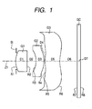
- Fig. 1 shows a single focus lens (first exemplary configuration) according to the embodiment of the invention.
- This exemplary configuration corresponds to a lens configuration according to a first numerical value Example (Figs. 3 and 4; described later).
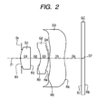
- Fig. 2 shows another single focus lens (second exemplary configuration).
- the exemplary configuration of Fig. 2 corresponds to a lens configuration according to a second numerical value Example (Figs. 5 and 6; described later).
- Symbol Di represents the surface interval on the optical axis Z1 between the ith surface and the (i + 1)th surface.
- the two exemplary configurations have the same basic configuration, and hence the configuration of the single focus lens shown in Fig. 1 will be described below.
- This single focus lens is suitable for use in small apparatus having an imaging function such as PDAs (personal digital assistants), video cameras, and digital still cameras.
- This single focus lens is provided with a first lens G1, a second lens G2, and a third lens G3 which are arranged along the optical axis Z1 in this order from the object side.
- An aperture stop St is disposed on the optical axis Z1 on the object side of the image-side surface of the first lens G1. It is preferable that the aperture stop St be disposed on the optical axis Z1 between the object-side surface and the image-side surface of the first lens G1.
- An imaging device such as a CCD sensor (not shown) is disposed in the image-forming plane (imaging plane) of this single focus lens.
- Various optical members GC may be disposed between the third lens G3 and the imaging plane in accordance with the configuration of a camera to which the lens is attached.
- a plate-like optical member GC such as a cover glass for imaging surface protection or one of various optical filters may be disposed there.
- the first lens G1 be an aspherical lens made of a glass material. It is preferable that each of the second lens G2 and the third lens G3 be an aspherical lens made of a plastic material.
- the first lens G1 has positive power because the object-side surface is a convex surface.
- the second lens G2 is a negative meniscus lens in which the object-side surface is a concave surface on its paraxial axis.
- the third lens G3 is an aspherical lens in which the object-side surface is a convex surface on its paraxial axis.
- the object-side surface of the third lens G3 be shaped in such a manner that its positive power decreases as the position goes outward. It is preferable that the image-side surface of the third lens G3 be a concave surface (i.e., recessed) on its paraxial axis, its negative power decrease as the position goes away from the center, and its power turn positive at a certain position further away from the center.
- This single focus lens satisfies the following condition formulae, where f is the focal length of the entire lens, f1 is the focal length of the first lens G1, vdA is the Abbe number of the first lens G1, vdB is the Abbe number of the second lens G2, NdA is the refractive index at the d-line of the first lens G1, NdB is the refractive index for at the d-line of the second lens G2, RA is the paraxial radius of curvature of the object-side surface of the first lens G1, L is the distance along the optical axis Z1 between the object-side surface of the first lens G1 and the image-forming position, and D is the maximum image height.
- the parameter L is such that the thickness of the optical member GC such as a cover glass is air-converted. 0.6 ⁇ f ⁇ 1 / f ⁇ 1.5 69 ⁇ v dA 24 ⁇ v dB ⁇ 32 NdA ⁇ 1.55 1.48 ⁇ NdB ⁇ 1.65 L / D ⁇ 1.8 0.30 ⁇ RA / f ⁇ 0.40
- This single focus lens is implemented as a compact, high-performance lens system though the number of lenses is as small as three, because, as described below, sufficient compactness is attained because of satisfaction of the condition formulae (1), (6), and (7) and the refractive index and the dispersion characteristic of the lens material of each of the first lens G1 and the second lens G2 are optimized because of satisfaction of the condition formulae (2), (3), (4), and (5).
- the condition formula (1) relates to the focal length f1 of the first lens G1.
- the parameter f1/f being out of the above numerical value range is not preferable, because the total length becomes too long if f1/f is greater than the above numerical value range and the pupil becomes too short if f1/f is smaller than the above numerical value range.
- the condition formula (6) relates to the ratio of the total optical length L along the optical axis Z1 to the maximum image height D. If the ratio L/D is greater than the above numerical value range, the total lens system cannot be made sufficiently compact.
- the condition formula (7) relates to the radius RA of curvature of the front surface of the first lens G1.
- the parameter RA/f being out of the above numerical value range is not preferable, because it is difficult to make the lens total length sufficiently short if RA/f is greater than the above numerical value range and it is difficult to correct for the spherical aberration and the curvature of field if RA/f is smaller than the above numerical value range.
- the power is made relatively large by decreasing the radius Rl of curvature of the front surface of the first lens G1 and the total length is thereby shortened.
- the condition formulae (2) and (4) relate to the characteristics of the lens material of the first lens G1.
- the chromatic aberration and the curvature of field can be corrected for properly by using a lens material having a large Abbe number and a small refractive index for the first lens G1 having positive power so that the condition formulae (2) and (4) are satisfied.
- the condition formulae (3) and (5) relate to the characteristics of the lens material of the second lens G2. If vdB and NdB are within the above numerical value ranges, the combination of the first lens G1 and the second lens G2 can be given necessary and sufficient performance in terms of the color aberration and the curvature of field.
- the third lens G3 can be given good performance by forming it with a material such as an acrylic resin or a cycloolefin polymer that has an Abbe number of 55 to 60, is inexpensive and easy to acquire, and is optically stable (e.g., low in strain).
- a material such as an acrylic resin or a cycloolefin polymer that has an Abbe number of 55 to 60, is inexpensive and easy to acquire, and is optically stable (e.g., low in strain).
- the total length, including the aperture stop St, of this single focus lens can be shortened by disposing the aperture stop St on the optical axis Z1 on the object side of the image-side surface of the first lens G1, preferably on the optical axis Z1 between the object-side surface and the image-side surface of the first lens G1.
- great aberration correcting effects can be obtained by employing proper aspherical surfaces as the surfaces of each lens.
- greater effects of correcting for aberrations including the curvature of field can be obtained by properly designing each aspherical surface (more specifically, the shapes of its paraxial portion and peripheral portion) of the third lens G3.
- the single focus lens according to the embodiment is implemented as a compact, high-performance lens system though the number of lenses is as small as three by, for example, optimizing the lens materials of and the power allocations to the first lens G1 and the second lens G2 so that the prescribed condition formulae are satisfied.
- Figs. 3 and 4 show specific lens data (Example 1) corresponding to the configuration of the single focus lens shown in Fig. 1. More specifically, Fig. 3 shows basic lens data and Fig. 4 shows data relating to the aspherical surfaces. Figs. 5 and 6 show specific lens data (Example 2) corresponding to the configuration of the single focus lens shown in Fig. 2. More specifically, Fig. 5 shows basic lens data and Fig. 6 shows data relating to the aspherical surfaces.
- radius Ri of curvature a value of the radius of curvature of the ith surface as numbered from the object side is shown (symbol Ri is the same as shown in Figs. 1 and 2).
- surface interval Di a value of the surface interval on the optical axis Z1 between the ith surface Si and the (i + 1)th surface Si+1 is shown.
- the unit of the radius Ri of curvature and the surface interval Di is millimeter (mm).
- the aperture stop St is disposed on the optical axis Z1 at a position that is distant from the object-side surface of the first lens G1 by 0.05 mm to the image side.
- the aperture stop St is disposed on the optical axis Z1 at a position that is distant from the object-side surface of the first lens G1 by 0.1 mm to the image side.
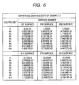
- Figs. 4 and 6 show the data of the aspherical surfaces of the single focus lenses of Examples 1 and 2.
- symbol "E” means that the numerical value following it is an exponent of a power having 10 as a base and the numerical value before “E” is multiplied by the power.
- "1.0E-02" means 1.0 x 10 -2 .
- the data of each aspherical surface are values of the coefficients A i and K of the following Equation (A) representing an aspherical surface. That is, the parameter Z means the length (mm) of the perpendicular from a point on the aspherical surface having a height h as measured from the optical axis Z1 to the tangential plane to the aspherical surface at its top (the tangential plane is perpendicular to the optical axis Z1).
- Each aspherical surface of the single focus lens of each Example is represented by effectively using the even-order aspherical coefficients A 4 , A 6 , A 8 , and A 10 and the odd-order aspherical coefficients A 3 , A 5 , A 7 , and A 9 :
- Z C ⁇ h 2 / 1 + 1 - K ⁇ C 2 ⁇ h 2 1 / 2 + A 3 ⁇ h 3 + A 4 ⁇ h 4 + A 5 ⁇ h 5 + A 6 ⁇ h 6 + A 7 ⁇ h 7 + A 8 ⁇ h 8 + A 9 ⁇ h 9 + A 10 ⁇ h 10
- Z depth (mm) of a point on the aspherical surface
- h distance (mm) between the point on the aspherical surface and the optical axis Z1 (i.e., height of the point)
- K eccentricity
- R paraxial radius of curvature
- a i
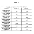
- Fig. 7 summarizes, for each Example, values of the parameters to which the respective condition formulae are directed. As seen from Fig. 7, the parameter values of each Example are within the numerical value ranges of the condition formulae, respectively.
- Figs. 8A-8C show the spherical aberration, astigmatism, and distortion, respectively, of the single focus lens of Example 1.
- Each aberration diagram shows an aberration curve(s) at the d-line used as a reference wavelength.
- the spherical aberration diagram (Fig. 8A) also shows aberration curves at the g-line (wavelength: 435.8 nm) and the C-line (wavelength: 656.3 nm).
- a solid-line aberration curve corresponds to the sagittal direction and a broken-line aberration curve corresponds to the tangential direction.
- the parameter ⁇ represents the half angle of view.
- Figs. 9A-9C show the aberrations of the single focus lens of Example 2.
- the invention is not limited to the above embodiment and Examples and various modifications are possible.
- the values of the radii of curvature of the lens surfaces, the surface intervals, the refractive indices of the lenses, etc. are not limited to the values used in the above numerical value Examples and may have other values.
Landscapes
- Physics & Mathematics (AREA)
- General Physics & Mathematics (AREA)
- Optics & Photonics (AREA)
- Lenses (AREA)
Abstract
Description
- The present invention relates to a single focus lens that is suitable for use in small apparatus having an imaging function such as cell phones with a camera, PDAs (personal digital assistants), and digital still cameras.
- Imaging apparatus such as digital still cameras employ an imaging device such as a CCD (charge-coupled device) sensor or a CMOS (complementary metal oxide semiconductor) sensor. In recent years, such imaging devices have been miniaturized to a large extent. Accordingly, imaging apparatus main bodies and lenses mounted thereon have come to be required to be reduced in size and weight. On the other hand, in recent years, imaging devices having a large number of pixels have been developed to attain high image quality and, accordingly, lens systems have come to be required to be high in such performance as resolution and contrast.
- An example of imaging lenses used in such imaging apparatus is one disclosed in
JP-A-10-48516 JP-A-10-48516 - As described above, recent imaging devices have been miniaturized and increased in the number of pixels and, accordingly, imaging lenses have come to be required to exhibit a high resolution and be high in the degree of compactness. Although the imaging lens of
JP-A-10-48516 - An object of an illustrative, non-limiting embodiment of the invention is to provide a single focus lens, which is a compact, high-performance lens system though the number of lenses is small.
- A single focus lens according to one aspect of the invention includes: in order from an object side of the single focus lens, a first lens having positive power and having a convex surface on the object side; a second lens of a negative meniscus lens and having a concave surface of the object side on its paraxial axis; and a third lens of an aspherical lens having a convex surface on the object side on its paraxial axis, wherein the single focus lens satisfies conditions (1) to (7):





wherein
f represents a focal length of the single focus lens;
f1 represents a focal length of the first lens;
vdA represents Abbe number of the first lens;
vdB represents Abbe number of the second lens;
NdA represents a refractive index at the d-line of the first lens;
NdB represents a refractive index at the d-line of the second lens;
RA represents a paraxial radius of curvature of an object-side surface of the first lens;
L represents a distance along an optical axis between the object-side surface of the first lens and an image-forming position; and
D represents a maximum image height. - The single focus lens according to one aspect of the invention may further includes a stop which is disposed, on the optical axis, on the object side of an image-side surface of the first lens.
- A single focus lens according to one aspect of the invention is implemented as a compact, high-performance lens system is realized though the number of lenses is as small as three by securing sufficient compactness by satisfying the condition formulae (1), (6), and (7) and optimizing the lens materials of the first lens and the second lens by satisfying the condition formulae (2), (3), (4), and (5).
- The features of the invention will appear more fully upon consideration of the exemplary embodiment of the invention, which are schematically set forth in the drawings, in which:
- Fig. 1 is a sectional view of a single focus lens (first exemplary configuration) according to an exemplary embodiment of the present invention;
- Fig. 2 is a sectional view of another single focus lens (second exemplary configuration) according to an exemplary embodiment of the invention;
- Fig. 3 shows basic lens data of a single focus lens of Example 1;
- Fig. 4 shows data relating to aspherical surfaces of the single focus lens of Example 1;
- Fig. 5 shows basic lens data of a single focus lens of Example 2;
- Fig. 6 shows data relating to aspherical surfaces of the single focus lens of Example 2;
- Fig. 7 summarizes, for each Example, values of parameters to which respective condition formulae are directed;
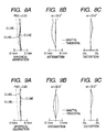
- Figs. 8A-8C are aberration diagrams showing various aberrations of the single focus lens of Example 1; Figs. 8A-8C show the spherical aberration, astigmatism, and distortion, respectively; and
- Figs. 9A-9C are aberration diagrams showing various aberrations of the single focus lens of Example 2; Figs. 9A-9CC show the spherical aberration, astigmatism, and distortion, respectively.
- Although the invention will be described below with reference to the exemplary embodiments thereof, the following exemplary embodiments and modifications do not restrict the invention.
- According to an exemplary embodiment, a single focus lens is provided with the first lens G1 which has positive power and whose object-side surface is a convex surface, the second lens which is a negative meniscus lens and whose object-side surface is a concave surface on its paraxial axis, and the third lens which is an aspherical lens and whose object-side surface is a convex surface on its paraxial axis in such a manner that they are arranged in this order from the object side. And sufficient compactness is secured and the lens materials of the first lens and the second lens are optimized by satisfying the prescribed condition formulae. As a result, a compact, high-performance lens system can be realized though the number of lenses is as small as three.
- Exemplary embodiments of the present invention will be hereinafter described in detail with reference to the drawings.
- Fig. 1 shows a single focus lens (first exemplary configuration) according to the embodiment of the invention. This exemplary configuration corresponds to a lens configuration according to a first numerical value Example (Figs. 3 and 4; described later). Fig. 2 shows another single focus lens (second exemplary configuration). The exemplary configuration of Fig. 2 corresponds to a lens configuration according to a second numerical value Example (Figs. 5 and 6; described later). In Figs. 1 and 2, symbol Ri represents the radius of curvature of the ith surface (i = 1 to 8) as numbered from the object side to the image side (image formation side), the radius of curvature of the object-side end surface being represented by R1. Symbol Di represents the surface interval on the optical axis Z1 between the ith surface and the (i + 1)th surface. The two exemplary configurations have the same basic configuration, and hence the configuration of the single focus lens shown in Fig. 1 will be described below.
- This single focus lens is suitable for use in small apparatus having an imaging function such as PDAs (personal digital assistants), video cameras, and digital still cameras. This single focus lens is provided with a first lens G1, a second lens G2, and a third lens G3 which are arranged along the optical axis Z1 in this order from the object side. An aperture stop St is disposed on the optical axis Z1 on the object side of the image-side surface of the first lens G1. It is preferable that the aperture stop St be disposed on the optical axis Z1 between the object-side surface and the image-side surface of the first lens G1.
- An imaging device such as a CCD sensor (not shown) is disposed in the image-forming plane (imaging plane) of this single focus lens. Various optical members GC may be disposed between the third lens G3 and the imaging plane in accordance with the configuration of a camera to which the lens is attached. For example, a plate-like optical member GC such as a cover glass for imaging surface protection or one of various optical filters may be disposed there.
- It is preferable that the first lens G1 be an aspherical lens made of a glass material. It is preferable that each of the second lens G2 and the third lens G3 be an aspherical lens made of a plastic material. The first lens G1 has positive power because the object-side surface is a convex surface. The second lens G2 is a negative meniscus lens in which the object-side surface is a concave surface on its paraxial axis. The third lens G3 is an aspherical lens in which the object-side surface is a convex surface on its paraxial axis.
- It is preferable that the object-side surface of the third lens G3 be shaped in such a manner that its positive power decreases as the position goes outward. It is preferable that the image-side surface of the third lens G3 be a concave surface (i.e., recessed) on its paraxial axis, its negative power decrease as the position goes away from the center, and its power turn positive at a certain position further away from the center.
- This single focus lens satisfies the following condition formulae, where f is the focal length of the entire lens, f1 is the focal length of the first lens G1, vdA is the Abbe number of the first lens G1, vdB is the Abbe number of the second lens G2, NdA is the refractive index at the d-line of the first lens G1, NdB is the refractive index for at the d-line of the second lens G2, RA is the paraxial radius of curvature of the object-side surface of the first lens G1, L is the distance along the optical axis Z1 between the object-side surface of the first lens G1 and the image-forming position, and D is the maximum image height. The parameter L is such that the thickness of the optical member GC such as a cover glass is air-converted.


- Next, the workings and advantages of the single focus lens having the above configuration will be described.
- This single focus lens is implemented as a compact, high-performance lens system though the number of lenses is as small as three, because, as described below, sufficient compactness is attained because of satisfaction of the condition formulae (1), (6), and (7) and the refractive index and the dispersion characteristic of the lens material of each of the first lens G1 and the second lens G2 are optimized because of satisfaction of the condition formulae (2), (3), (4), and (5).
- The condition formula (1) relates to the focal length f1 of the first lens G1. The parameter f1/f being out of the above numerical value range is not preferable, because the total length becomes too long if f1/f is greater than the above numerical value range and the pupil becomes too short if f1/f is smaller than the above numerical value range. The condition formula (6) relates to the ratio of the total optical length L along the optical axis Z1 to the maximum image height D. If the ratio L/D is greater than the above numerical value range, the total lens system cannot be made sufficiently compact. The condition formula (7) relates to the radius RA of curvature of the front surface of the first lens G1. The parameter RA/f being out of the above numerical value range is not preferable, because it is difficult to make the lens total length sufficiently short if RA/f is greater than the above numerical value range and it is difficult to correct for the spherical aberration and the curvature of field if RA/f is smaller than the above numerical value range. In this single focus lens, the power is made relatively large by decreasing the radius Rl of curvature of the front surface of the first lens G1 and the total length is thereby shortened.
- The condition formulae (2) and (4) relate to the characteristics of the lens material of the first lens G1. The chromatic aberration and the curvature of field can be corrected for properly by using a lens material having a large Abbe number and a small refractive index for the first lens G1 having positive power so that the condition formulae (2) and (4) are satisfied. The condition formulae (3) and (5) relate to the characteristics of the lens material of the second lens G2. If vdB and NdB are within the above numerical value ranges, the combination of the first lens G1 and the second lens G2 can be given necessary and sufficient performance in terms of the color aberration and the curvature of field. The third lens G3 can be given good performance by forming it with a material such as an acrylic resin or a cycloolefin polymer that has an Abbe number of 55 to 60, is inexpensive and easy to acquire, and is optically stable (e.g., low in strain).
- The total length, including the aperture stop St, of this single focus lens can be shortened by disposing the aperture stop St on the optical axis Z1 on the object side of the image-side surface of the first lens G1, preferably on the optical axis Z1 between the object-side surface and the image-side surface of the first lens G1. Furthermore, in this single focus lens, great aberration correcting effects can be obtained by employing proper aspherical surfaces as the surfaces of each lens. In particular, greater effects of correcting for aberrations including the curvature of field can be obtained by properly designing each aspherical surface (more specifically, the shapes of its paraxial portion and peripheral portion) of the third lens G3.
- As described above, the single focus lens according to the embodiment is implemented as a compact, high-performance lens system though the number of lenses is as small as three by, for example, optimizing the lens materials of and the power allocations to the first lens G1 and the second lens G2 so that the prescribed condition formulae are satisfied.
- Next, specific numerical value Examples corresponding to the above single focus lenses according to the embodiment will be described. Two numerical value Examples (Examples 1 and 2) will be described together below.
- Figs. 3 and 4 show specific lens data (Example 1) corresponding to the configuration of the single focus lens shown in Fig. 1. More specifically, Fig. 3 shows basic lens data and Fig. 4 shows data relating to the aspherical surfaces. Figs. 5 and 6 show specific lens data (Example 2) corresponding to the configuration of the single focus lens shown in Fig. 2. More specifically, Fig. 5 shows basic lens data and Fig. 6 shows data relating to the aspherical surfaces.
- In the lens data of each of Figs. 3 and 5, in the column "surface Si," surface number Si denotes the ith surface (i = 1 to 8) of the single focus lens of each Example as numbered from the object side to the image side, the object-side end surface being denoted by S1. In the column "radius Ri of curvature," a value of the radius of curvature of the ith surface as numbered from the object side is shown (symbol Ri is the same as shown in Figs. 1 and 2). In the column "surface interval Di," a value of the surface interval on the optical axis Z1 between the ith surface Si and the (i + 1)th surface Si+1 is shown. The unit of the radius Ri of curvature and the surface interval Di is millimeter (mm). In the columns "refractive index Ndj" and "Abbe number vdj," values of the refractive index and the Abbe number at the d-line (wavelength: 587.6 nm) of the jth optical element (j = 1 to 4; including the optical member GC) as numbered from the object side are shown. Each of Figs. 3 and 5 also shows other various data, that is, values of the paraxial focal length f (mm), the F number (F No.), and the angle 2ω of view (ω: half angle of view) of the entire system.
- In the single focus lens of Example 1, the aperture stop St is disposed on the optical axis Z1 at a position that is distant from the object-side surface of the first lens G1 by 0.05 mm to the image side. In the single focus lens of Example 2, the aperture stop St is disposed on the optical axis Z1 at a position that is distant from the object-side surface of the first lens G1 by 0.1 mm to the image side.
- In the lens data of Figs. 3 and 5, symbol "*" that is attached, on the left side, to each surface number denoting a lens surface means that the lens surface is an aspherical surface. In the single focus lens of each Example, both surfaces of each of the first lens G1, the second lens G2, and the third lens G3 are aspherical surfaces. In the basic lens data of Figs. 3 and 5, the values of the radii of curvature of these aspherical surfaces are values of the radii of curvature of their portions close to the optical axis Z1.
- Figs. 4 and 6 show the data of the aspherical surfaces of the single focus lenses of Examples 1 and 2. As for the numerical values of the aspherical surface data, symbol "E" means that the numerical value following it is an exponent of a power having 10 as a base and the numerical value before "E" is multiplied by the power. For example, "1.0E-02" means 1.0 x 10⁻².
- The data of each aspherical surface are values of the coefficients Ai and K of the following Equation (A) representing an aspherical surface. That is, the parameter Z means the length (mm) of the perpendicular from a point on the aspherical surface having a height h as measured from the optical axis Z1 to the tangential plane to the aspherical surface at its top (the tangential plane is perpendicular to the optical axis Z1). Each aspherical surface of the single focus lens of each Example is represented by effectively using the even-order aspherical coefficients A4, A6, A8, and A10 and the odd-order aspherical coefficients A3, A5, A7, and A9:

where
Z: depth (mm) of a point on the aspherical surface;
h: distance (mm) between the point on the aspherical surface and the optical axis Z1 (i.e., height of the point);
K: eccentricity;
C: paraxial curvature (= 1/R; R: paraxial radius of curvature); and
Ai: ith-order aspherical coefficient. - Fig. 7 summarizes, for each Example, values of the parameters to which the respective condition formulae are directed. As seen from Fig. 7, the parameter values of each Example are within the numerical value ranges of the condition formulae, respectively.
- Figs. 8A-8C show the spherical aberration, astigmatism, and distortion, respectively, of the single focus lens of Example 1. Each aberration diagram shows an aberration curve(s) at the d-line used as a reference wavelength. The spherical aberration diagram (Fig. 8A) also shows aberration curves at the g-line (wavelength: 435.8 nm) and the C-line (wavelength: 656.3 nm). In the astigmatism diagram (Fig. 8B), a solid-line aberration curve corresponds to the sagittal direction and a broken-line aberration curve corresponds to the tangential direction. The parameter ω represents the half angle of view. Likewise, Figs. 9A-9C show the aberrations of the single focus lens of Example 2.
- As seen from the above numerical value data and aberration diagrams, in each Example, the aberrations are corrected for properly and a compact lens system is realized though the number of lenses is small.
- The invention is not limited to the above embodiment and Examples and various modifications are possible. For example, the values of the radii of curvature of the lens surfaces, the surface intervals, the refractive indices of the lenses, etc. are not limited to the values used in the above numerical value Examples and may have other values.
- The present application claims foreign priority based on
Japanese Patent Application No. JP2005-284712
Claims (2)
- A single focus lens comprising: in order from an object side of the single focus lens,
a first lens having positive power and having a convex surface on the object side;
a second lens of a negative meniscus lens and having a concave surface of the object side on its paraxial axis; and
a third lens of an aspherical lens having a convex surface on the object side on its paraxial axis,
wherein the single focus lens satisfies conditions (1) to (7):


wherein
f represents a focal length of the single focus lens;
f1 represents a focal length of the first lens;
vdA represents Abbe number of the first lens;
vdB represents Abbe number of the second lens;
NdA represents a refractive index at the d-line of the first lens;
NdB represents a refractive index at the d-line of the second lens;
RA represents a paraxial radius of curvature of an object-side surface of the first lens;
L represents a distance along an optical axis between the object-side surface of the first lens and an image-forming position; and
D represents a maximum image height. - The single focus lens according to claim 1, further comprising a stop disposed, on the optical axis, on the object side of an image-side surface of the first lens.
Applications Claiming Priority (1)
| Application Number | Priority Date | Filing Date | Title |
|---|---|---|---|
| JP2005284712A JP4804856B2 (en) | 2005-09-29 | 2005-09-29 | Single focus lens |
Publications (1)
| Publication Number | Publication Date |
|---|---|
| EP1770424A1 true EP1770424A1 (en) | 2007-04-04 |
Family
ID=37459499
Family Applications (1)
| Application Number | Title | Priority Date | Filing Date |
|---|---|---|---|
| EP06020413A Ceased EP1770424A1 (en) | 2005-09-29 | 2006-09-28 | Compact imaging lens having three single lenses |
Country Status (6)
| Country | Link |
|---|---|
| US (1) | US7408725B2 (en) |
| EP (1) | EP1770424A1 (en) |
| JP (1) | JP4804856B2 (en) |
| KR (1) | KR100773812B1 (en) |
| CN (1) | CN1940626B (en) |
| TW (1) | TWI309728B (en) |
Cited By (1)
| Publication number | Priority date | Publication date | Assignee | Title |
|---|---|---|---|---|
| CN102193168A (en) * | 2010-03-04 | 2011-09-21 | 大立光电股份有限公司 | Photographic lens system |
Families Citing this family (83)
| Publication number | Priority date | Publication date | Assignee | Title |
|---|---|---|---|---|
| JP2007264181A (en) * | 2006-03-28 | 2007-10-11 | Fujinon Corp | Imaging lens |
| JP4890943B2 (en) * | 2006-05-26 | 2012-03-07 | 富士フイルム株式会社 | Imaging lens |
| US7460314B2 (en) * | 2007-02-28 | 2008-12-02 | E-Pin Optical Industry Co., Ltd | Three-piece type optical lens |
| TW200837418A (en) * | 2007-03-13 | 2008-09-16 | Asia Optical Co Inc | Slim lens |
| KR100843467B1 (en) * | 2007-03-16 | 2008-07-03 | 삼성전기주식회사 | Ultra compact imaging optics |
| JP2008233221A (en) * | 2007-03-16 | 2008-10-02 | Matsushita Electric Ind Co Ltd | Shooting lens |
| US8201743B2 (en) * | 2007-06-28 | 2012-06-19 | Symbol Technologies, Inc. | Bar code reader with improved lens for imaging with balanced astigmatism |
| CN100573223C (en) * | 2007-08-09 | 2009-12-23 | 鸿富锦精密工业(深圳)有限公司 | Low Height Lens System |
| TWM341858U (en) * | 2007-12-19 | 2008-10-01 | Largan Precision Co Ltd | Auto-focus module |
| EP4336447B1 (en) | 2008-05-20 | 2025-05-07 | Adeia Imaging LLC | Capturing and processing of images using monolithic camera array with heterogeneous imagers |
| US8866920B2 (en) | 2008-05-20 | 2014-10-21 | Pelican Imaging Corporation | Capturing and processing of images using monolithic camera array with heterogeneous imagers |
| US11792538B2 (en) | 2008-05-20 | 2023-10-17 | Adeia Imaging Llc | Capturing and processing of images including occlusions focused on an image sensor by a lens stack array |
| US8369030B2 (en) * | 2009-05-25 | 2013-02-05 | Ricoh Company, Limited | Image forming lens, camera device, and handheld terminal |
| JP5308915B2 (en) * | 2009-05-28 | 2013-10-09 | 株式会社オプトロジック | Imaging lens |
| TWI408408B (en) | 2009-06-19 | 2013-09-11 | E Pin Optical Industry Co Ltd | Miniature three-piece optical lens with short back focal length |
| TWI404972B (en) * | 2009-06-19 | 2013-08-11 | Largan Precision Co | Optical lens system for taking image |
| WO2011063347A2 (en) | 2009-11-20 | 2011-05-26 | Pelican Imaging Corporation | Capturing and processing of images using monolithic camera array with heterogeneous imagers |
| US20120012748A1 (en) | 2010-05-12 | 2012-01-19 | Pelican Imaging Corporation | Architectures for imager arrays and array cameras |
| TW201200928A (en) | 2010-06-30 | 2012-01-01 | E Pin Optical Industry Co Ltd | Three-piece pickup lens |
| US8878950B2 (en) | 2010-12-14 | 2014-11-04 | Pelican Imaging Corporation | Systems and methods for synthesizing high resolution images using super-resolution processes |
| EP2708019B1 (en) | 2011-05-11 | 2019-10-16 | FotoNation Limited | Systems and methods for transmitting and receiving array camera image data |
| US20130265459A1 (en) | 2011-06-28 | 2013-10-10 | Pelican Imaging Corporation | Optical arrangements for use with an array camera |
| EP2726930A4 (en) | 2011-06-28 | 2015-03-04 | Pelican Imaging Corp | OPTICAL CONFIGURATIONS FOR USE WITH A MATRIX CAMERA |
| WO2013043751A1 (en) | 2011-09-19 | 2013-03-28 | Pelican Imaging Corporation | Systems and methods for controlling aliasing in images captured by an array camera for use in super resolution processing using pixel apertures |
| JP6140709B2 (en) | 2011-09-28 | 2017-05-31 | ペリカン イメージング コーポレイション | System and method for encoding and decoding bright-field image files |
| WO2013126578A1 (en) | 2012-02-21 | 2013-08-29 | Pelican Imaging Corporation | Systems and methods for the manipulation of captured light field image data |
| US9210392B2 (en) | 2012-05-01 | 2015-12-08 | Pelican Imaging Coporation | Camera modules patterned with pi filter groups |
| EP2873028A4 (en) | 2012-06-28 | 2016-05-25 | Pelican Imaging Corp | SYSTEMS AND METHODS FOR DETECTING CAMERA NETWORKS, OPTICAL NETWORKS AND DEFECTIVE SENSORS |
| US20140002674A1 (en) | 2012-06-30 | 2014-01-02 | Pelican Imaging Corporation | Systems and Methods for Manufacturing Camera Modules Using Active Alignment of Lens Stack Arrays and Sensors |
| EP3869797B1 (en) | 2012-08-21 | 2023-07-19 | Adeia Imaging LLC | Method for depth detection in images captured using array cameras |
| US20140055632A1 (en) | 2012-08-23 | 2014-02-27 | Pelican Imaging Corporation | Feature based high resolution motion estimation from low resolution images captured using an array source |
| WO2014043641A1 (en) | 2012-09-14 | 2014-03-20 | Pelican Imaging Corporation | Systems and methods for correcting user identified artifacts in light field images |
| US20140092281A1 (en) | 2012-09-28 | 2014-04-03 | Pelican Imaging Corporation | Generating Images from Light Fields Utilizing Virtual Viewpoints |
| WO2014078443A1 (en) | 2012-11-13 | 2014-05-22 | Pelican Imaging Corporation | Systems and methods for array camera focal plane control |
| WO2014130849A1 (en) | 2013-02-21 | 2014-08-28 | Pelican Imaging Corporation | Generating compressed light field representation data |
| WO2014133974A1 (en) | 2013-02-24 | 2014-09-04 | Pelican Imaging Corporation | Thin form computational and modular array cameras |
| US9638883B1 (en) | 2013-03-04 | 2017-05-02 | Fotonation Cayman Limited | Passive alignment of array camera modules constructed from lens stack arrays and sensors based upon alignment information obtained during manufacture of array camera modules using an active alignment process |
| WO2014138695A1 (en) | 2013-03-08 | 2014-09-12 | Pelican Imaging Corporation | Systems and methods for measuring scene information while capturing images using array cameras |
| US8866912B2 (en) | 2013-03-10 | 2014-10-21 | Pelican Imaging Corporation | System and methods for calibration of an array camera using a single captured image |
| US9521416B1 (en) | 2013-03-11 | 2016-12-13 | Kip Peli P1 Lp | Systems and methods for image data compression |
| WO2014164550A2 (en) | 2013-03-13 | 2014-10-09 | Pelican Imaging Corporation | System and methods for calibration of an array camera |
| WO2014164909A1 (en) | 2013-03-13 | 2014-10-09 | Pelican Imaging Corporation | Array camera architecture implementing quantum film sensors |
| US9106784B2 (en) | 2013-03-13 | 2015-08-11 | Pelican Imaging Corporation | Systems and methods for controlling aliasing in images captured by an array camera for use in super-resolution processing |
| WO2014165244A1 (en) | 2013-03-13 | 2014-10-09 | Pelican Imaging Corporation | Systems and methods for synthesizing images from image data captured by an array camera using restricted depth of field depth maps in which depth estimation precision varies |
| WO2014153098A1 (en) | 2013-03-14 | 2014-09-25 | Pelican Imaging Corporation | Photmetric normalization in array cameras |
| WO2014159779A1 (en) | 2013-03-14 | 2014-10-02 | Pelican Imaging Corporation | Systems and methods for reducing motion blur in images or video in ultra low light with array cameras |
| EP4604059A3 (en) | 2013-03-15 | 2025-09-17 | Adeia Imaging LLC | Systems and methods for stereo imaging with camera arrays |
| US9633442B2 (en) | 2013-03-15 | 2017-04-25 | Fotonation Cayman Limited | Array cameras including an array camera module augmented with a separate camera |
| US9445003B1 (en) | 2013-03-15 | 2016-09-13 | Pelican Imaging Corporation | Systems and methods for synthesizing high resolution images using image deconvolution based on motion and depth information |
| US10122993B2 (en) | 2013-03-15 | 2018-11-06 | Fotonation Limited | Autofocus system for a conventional camera that uses depth information from an array camera |
| WO2014150856A1 (en) | 2013-03-15 | 2014-09-25 | Pelican Imaging Corporation | Array camera implementing quantum dot color filters |
| US9497429B2 (en) | 2013-03-15 | 2016-11-15 | Pelican Imaging Corporation | Extended color processing on pelican array cameras |
| US9898856B2 (en) | 2013-09-27 | 2018-02-20 | Fotonation Cayman Limited | Systems and methods for depth-assisted perspective distortion correction |
| US9185276B2 (en) | 2013-11-07 | 2015-11-10 | Pelican Imaging Corporation | Methods of manufacturing array camera modules incorporating independently aligned lens stacks |
| US10119808B2 (en) | 2013-11-18 | 2018-11-06 | Fotonation Limited | Systems and methods for estimating depth from projected texture using camera arrays |
| EP3075140B1 (en) | 2013-11-26 | 2018-06-13 | FotoNation Cayman Limited | Array camera configurations incorporating multiple constituent array cameras |
| WO2015134996A1 (en) | 2014-03-07 | 2015-09-11 | Pelican Imaging Corporation | System and methods for depth regularization and semiautomatic interactive matting using rgb-d images |
| US9247117B2 (en) | 2014-04-07 | 2016-01-26 | Pelican Imaging Corporation | Systems and methods for correcting for warpage of a sensor array in an array camera module by introducing warpage into a focal plane of a lens stack array |
| US9521319B2 (en) | 2014-06-18 | 2016-12-13 | Pelican Imaging Corporation | Array cameras and array camera modules including spectral filters disposed outside of a constituent image sensor |
| JP2017531976A (en) | 2014-09-29 | 2017-10-26 | フォトネイション ケイマン リミテッド | System and method for dynamically calibrating an array camera |
| TWI546562B (en) * | 2014-12-04 | 2016-08-21 | 先進光電科技股份有限公司 | Optical image capturing system |
| TWI572888B (en) * | 2015-01-21 | 2017-03-01 | 先進光電科技股份有限公司 | Optical image capturing system |
| US9942474B2 (en) | 2015-04-17 | 2018-04-10 | Fotonation Cayman Limited | Systems and methods for performing high speed video capture and depth estimation using array cameras |
| US10482618B2 (en) | 2017-08-21 | 2019-11-19 | Fotonation Limited | Systems and methods for hybrid depth regularization |
| EP3611552B1 (en) | 2018-08-16 | 2023-03-08 | Jabil Optics Germany GmbH | Camera lens system for an endoscope, method for producing a camera lens system and an endoscope |
| CA3109406C (en) | 2019-09-17 | 2023-01-10 | Boston Polarimetrics, Inc. | Systems and methods for surface modeling using polarization cues |
| EP4042366A4 (en) | 2019-10-07 | 2023-11-15 | Boston Polarimetrics, Inc. | SYSTEMS AND METHODS FOR EXPANSION OF SENSOR SYSTEMS AND IMAGING SYSTEMS WITH POLARIZATION |
| KR102558903B1 (en) | 2019-11-30 | 2023-07-24 | 보스턴 폴라리메트릭스, 인크. | System and Method for Segmenting Transparent Objects Using Polarized Signals |
| CN115552486A (en) | 2020-01-29 | 2022-12-30 | 因思创新有限责任公司 | Systems and methods for characterizing object pose detection and measurement systems |
| CN115428028B (en) | 2020-01-30 | 2026-05-19 | 因思创新有限责任公司 | Systems and methods for synthesizing data for training models in different imaging modalities |
| WO2021243088A1 (en) | 2020-05-27 | 2021-12-02 | Boston Polarimetrics, Inc. | Multi-aperture polarization optical systems using beam splitters |
| TWI827857B (en) * | 2020-07-03 | 2024-01-01 | 先進光電科技股份有限公司 | Optical image capturing system |
| US12069227B2 (en) | 2021-03-10 | 2024-08-20 | Intrinsic Innovation Llc | Multi-modal and multi-spectral stereo camera arrays |
| US12020455B2 (en) | 2021-03-10 | 2024-06-25 | Intrinsic Innovation Llc | Systems and methods for high dynamic range image reconstruction |
| US11954886B2 (en) | 2021-04-15 | 2024-04-09 | Intrinsic Innovation Llc | Systems and methods for six-degree of freedom pose estimation of deformable objects |
| US11290658B1 (en) | 2021-04-15 | 2022-03-29 | Boston Polarimetrics, Inc. | Systems and methods for camera exposure control |
| US12067746B2 (en) | 2021-05-07 | 2024-08-20 | Intrinsic Innovation Llc | Systems and methods for using computer vision to pick up small objects |
| US12175741B2 (en) | 2021-06-22 | 2024-12-24 | Intrinsic Innovation Llc | Systems and methods for a vision guided end effector |
| US12340538B2 (en) | 2021-06-25 | 2025-06-24 | Intrinsic Innovation Llc | Systems and methods for generating and using visual datasets for training computer vision models |
| US12172310B2 (en) | 2021-06-29 | 2024-12-24 | Intrinsic Innovation Llc | Systems and methods for picking objects using 3-D geometry and segmentation |
| US11689813B2 (en) | 2021-07-01 | 2023-06-27 | Intrinsic Innovation Llc | Systems and methods for high dynamic range imaging using crossed polarizers |
| US12293535B2 (en) | 2021-08-03 | 2025-05-06 | Intrinsic Innovation Llc | Systems and methods for training pose estimators in computer vision |
| CN114217427B (en) * | 2022-02-23 | 2022-07-15 | 江西联益光学有限公司 | Optical lens |
Citations (5)
| Publication number | Priority date | Publication date | Assignee | Title |
|---|---|---|---|---|
| US20040190162A1 (en) * | 2003-03-31 | 2004-09-30 | Kenichi Sato | Single focus lens |
| US20050041306A1 (en) * | 2003-01-20 | 2005-02-24 | Eiki Matsuo | Imaging lens |
| US20050094292A1 (en) * | 2003-11-04 | 2005-05-05 | Eastman Kodak Company | Three element optical system |
| EP1562061A1 (en) * | 2002-10-25 | 2005-08-10 | Nagano Optics Laboratory Corporation | Imaging lens |
| JP2005345919A (en) * | 2004-06-04 | 2005-12-15 | Seiko Precision Inc | Imaging lens |
Family Cites Families (5)
| Publication number | Priority date | Publication date | Assignee | Title |
|---|---|---|---|---|
| JPH1048516A (en) | 1996-08-06 | 1998-02-20 | Hinode:Kk | Lens for CCD |
| DE60303153D1 (en) * | 2002-03-25 | 2006-04-06 | Konica Corp | Three-lens lens |
| JP2004212467A (en) * | 2002-12-27 | 2004-07-29 | Nidec Copal Corp | Photographic lens |
| JP4515728B2 (en) * | 2003-08-01 | 2010-08-04 | リコー光学株式会社 | Imaging lens and portable electronic device |
| CN2695994Y (en) * | 2004-03-06 | 2005-04-27 | 鸿富锦精密工业(深圳)有限公司 | Digital camera lens |
-
2005
- 2005-09-29 JP JP2005284712A patent/JP4804856B2/en not_active Expired - Fee Related
-
2006
- 2006-09-26 CN CN2006101543759A patent/CN1940626B/en not_active Expired - Fee Related
- 2006-09-28 TW TW095135916A patent/TWI309728B/en not_active IP Right Cessation
- 2006-09-28 KR KR1020060094632A patent/KR100773812B1/en not_active Expired - Fee Related
- 2006-09-28 US US11/528,446 patent/US7408725B2/en active Active
- 2006-09-28 EP EP06020413A patent/EP1770424A1/en not_active Ceased
Patent Citations (5)
| Publication number | Priority date | Publication date | Assignee | Title |
|---|---|---|---|---|
| EP1562061A1 (en) * | 2002-10-25 | 2005-08-10 | Nagano Optics Laboratory Corporation | Imaging lens |
| US20050041306A1 (en) * | 2003-01-20 | 2005-02-24 | Eiki Matsuo | Imaging lens |
| US20040190162A1 (en) * | 2003-03-31 | 2004-09-30 | Kenichi Sato | Single focus lens |
| US20050094292A1 (en) * | 2003-11-04 | 2005-05-05 | Eastman Kodak Company | Three element optical system |
| JP2005345919A (en) * | 2004-06-04 | 2005-12-15 | Seiko Precision Inc | Imaging lens |
Non-Patent Citations (1)
| Title |
|---|
| "Modern Optical Engineering - 3rd Edition", 1 January 2000, MCGRAW-HILL, NEW YORK, article WARREN J SMITH: "Modern Optical Engineering - 3rd Edition", pages: 61 - 90, XP055041402 * |
Cited By (2)
| Publication number | Priority date | Publication date | Assignee | Title |
|---|---|---|---|---|
| CN102193168A (en) * | 2010-03-04 | 2011-09-21 | 大立光电股份有限公司 | Photographic lens system |
| CN102193168B (en) * | 2010-03-04 | 2012-08-29 | 大立光电股份有限公司 | Photographic lens system |
Also Published As
| Publication number | Publication date |
|---|---|
| TWI309728B (en) | 2009-05-11 |
| KR100773812B1 (en) | 2007-11-06 |
| CN1940626A (en) | 2007-04-04 |
| JP2007094113A (en) | 2007-04-12 |
| CN1940626B (en) | 2012-08-29 |
| US20070070526A1 (en) | 2007-03-29 |
| US7408725B2 (en) | 2008-08-05 |
| KR20070036698A (en) | 2007-04-03 |
| JP4804856B2 (en) | 2011-11-02 |
| TW200717022A (en) | 2007-05-01 |
Similar Documents
| Publication | Publication Date | Title |
|---|---|---|
| US7408725B2 (en) | Single focus lens | |
| EP1795936B1 (en) | Compact imaging lens of the telephoto type with four single lenses | |
| EP1840619B1 (en) | Telephoto-type of imaging lens with five single lenses | |
| EP2090915B1 (en) | Imaging lens and imaging apparatus | |
| EP1868021B1 (en) | Compact imaging lens having four single lenses | |
| EP1845402B1 (en) | Compact imaging lens of the telephoto-type and having three single lenses | |
| EP1777941B1 (en) | Wide-angle imaging lens system | |
| EP1840616A1 (en) | Imaging lens | |
| EP1821129A1 (en) | Imaging lens | |
| JP3717483B2 (en) | Imaging lens | |
| EP1777569A1 (en) | Wide-angle imaging lens | |
| JP2011221561A (en) | Imaging lens | |
| US7440197B2 (en) | Image forming lens and portable information terminal | |
| CN113640968B (en) | Camera lens | |
| EP1860476A1 (en) | Imaging lens | |
| US7199948B1 (en) | Single focus lens | |
| US7738191B2 (en) | Single focus lens | |
| EP1840620A1 (en) | Compact imaging objective having three single lenses | |
| CN113640959B (en) | Image pickup lens | |
| US20020018303A1 (en) | Imaging lens device | |
| US20080225401A1 (en) | Compact imaging lens system | |
| JP4204351B2 (en) | Zoom lens | |
| CN102317832B (en) | camera lens |
Legal Events
| Date | Code | Title | Description |
|---|---|---|---|
| PUAI | Public reference made under article 153(3) epc to a published international application that has entered the european phase |
Free format text: ORIGINAL CODE: 0009012 |
|
| 17P | Request for examination filed |
Effective date: 20060928 |
|
| AK | Designated contracting states |
Kind code of ref document: A1 Designated state(s): AT BE BG CH CY CZ DE DK EE ES FI FR GB GR HU IE IS IT LI LT LU LV MC NL PL PT RO SE SI SK TR |
|
| AX | Request for extension of the european patent |
Extension state: AL BA HR MK YU |
|
| AKX | Designation fees paid |
Designated state(s): AT BE BG CH CY CZ DE DK EE ES FI FR GB GR HU IE IS IT LI LT LU LV MC NL PL PT RO SE SI SK TR |
|
| 17Q | First examination report despatched |
Effective date: 20090508 |
|
| RAP1 | Party data changed (applicant data changed or rights of an application transferred) |
Owner name: FUJIFILM CORPORATION |
|
| STAA | Information on the status of an ep patent application or granted ep patent |
Free format text: STATUS: THE APPLICATION HAS BEEN REFUSED |
|
| 18R | Application refused |
Effective date: 20130429 |