EP1770369A1 - A method for controlling a pedometer. - Google Patents
A method for controlling a pedometer. Download PDFInfo
- Publication number
- EP1770369A1 EP1770369A1 EP05425684A EP05425684A EP1770369A1 EP 1770369 A1 EP1770369 A1 EP 1770369A1 EP 05425684 A EP05425684 A EP 05425684A EP 05425684 A EP05425684 A EP 05425684A EP 1770369 A1 EP1770369 A1 EP 1770369A1
- Authority
- EP
- European Patent Office
- Prior art keywords
- steps
- regularity
- valid
- satisfied
- condition
- Prior art date
- Legal status (The legal status is an assumption and is not a legal conclusion. Google has not performed a legal analysis and makes no representation as to the accuracy of the status listed.)
- Granted
Links
Images


Classifications
-
- G—PHYSICS
- G01—MEASURING; TESTING
- G01C—MEASURING DISTANCES, LEVELS OR BEARINGS; SURVEYING; NAVIGATION; GYROSCOPIC INSTRUMENTS; PHOTOGRAMMETRY OR VIDEOGRAMMETRY
- G01C22/00—Measuring distance traversed on the ground by vehicles, persons, animals or other moving solid bodies, e.g. using odometers, using pedometers
- G01C22/006—Pedometers
Definitions
- the present invention relates to a method for controlling a pedometer based on the use of inertial sensors and to a pedometer implementing said method.
- a pedometer is a device that can be carried by a user and has the function of counting the number of steps during various walking or running activities for estimating accordingly the distance travelled.
- the indications supplied are useful for quantifying the motor activity performed by a person in the course of a given period, for instance, for clinical purposes, for assessing the athletic performance, or even just for simple personal interest.
- pedometer The reliability of a pedometer obviously depends on the precision in estimating the step length of the user at the various rates of locomotion, but also on the selectivity in recognizing and ignoring events not correlated to the gait??, which, however, cause perturbations resembling those produced by a step.
- many pedometers are based on the use of inertial sensors, which detect accelerations along a substantially vertical axis, and recognize that a step has been being made by a user when the time plot of the acceleration signal shows given morphological characteristics.
- a step is recognized when the pedometer detects a positive acceleration peak (i.e., a peak directed upwards) having an amplitude greater than a first threshold, followed, at a distance of some tenths of second, by a negative acceleration peak (directed downwards) having an amplitude greater than a second threshold.
- a positive acceleration peak i.e., a peak directed upwards
- a negative acceleration peak directed downwards
- a step is recognized when the pedometer detects a positive acceleration peak (i.e., a peak directed upwards) having an amplitude greater than a first threshold
- a negative acceleration peak directed downwards
- the aim of the present invention is to provide a method for controlling a pedometer and a pedometer which overcome the described above limitations.
- a method for controlling a pedometer and a pedometer are provided, as defined in Claims 1 and 15, respectively.
- a pedometer 1 is integrated within a portable electronic device, such as a cellphone 2.
- the pedometer 1 comprises an inertial sensor 3, a control unit 5, equipped with a nonvolatile-memory module (not illustrated herein), a display 6, and a communication interface 8, all housed on a card 9, which is, in turn, fixed within a casing 10 of the cellphone 2.
- the control unit 5 performs control functions of the pedometer 1 and, moreover, presides over bi-directional communication and over handling of the functions envisaged for the cellphone 2.
- the display 6, which is obviously arranged so as to be visible from the outside of the casing 10, can be used for displaying both information regarding the pedometer 1 and, more in general, information regarding the operation of the cellphone 2.
- the inertial sensor 3 is a linear accelerometer of a MEMS (micro-electromechanical systems) type and is mounted on the card 9 so as to have a detection axis Z substantially parallel to a longitudinal axis L of the casing 10 of the cellphone 2.
- the detection axis Z and the longitudinal axis L are substantially horizontal, when the cellphone 2 is resting on a surface, and substantially vertical or slightly inclined with respect to the vertical when the cellphone 2 is handled.
- the inertial sensor 3 supplies at output an acceleration signal A Z , which is correlated to the accelerations undergone by the inertial sensor 3 itself along the detection axis Z.
- the control unit 5 receives and processes the acceleration signal A Z as explained in detail hereinafter for identifying and counting a total number of valid steps N VT made by a user wearing or carrying the pedometer 1, for example, on his belt or on his shoulder.
- the control unit 5 is preferably configured for generating an estimate of the distance travelled by the user and other data, such as, for example, estimates of the average speed during movement and energy consumption.
- the total number of valid steps N VT and the other data possibly produced are sent to the display 6.
- the communication interface 8 in this case is based on the transceiver system (known and not shown) of the cellphone 2 and, preferably, also comprises a port (also known and not shown) for communication with a computer.
- the communication interface 8 can thus be used both for downloading the data produced by the pedometer 1 (amongst which at least the total number of valid steps N VT ) and for uploading operating parameters for the pedometer 1 into the control unit 5.
- the control unit 5 is configured for executing a control procedure, as illustrated with reference to Figures 3-8.
- an initialization step is executed (block 100, Figure 3), in which the total number of valid steps N VT , a second counter, hereinafter referred to as number of valid control steps N VC , and a third counter, hereinafter referred to as number of invalid steps N INV , are set to zero.
- the control unit 5 then executes a first counting procedure (block 110), based upon the sampling of the acceleration signal A z at a pre-determined frequency, for example 25 Hz.
- a pre-determined frequency for example 25 Hz.
- the user is considered at rest and the control unit 5 is considered as waiting to recognize, on the basis of the acceleration signal A Z , sequences of events corresponding to a sequence of steps that are close to one another, which satisfy pre-determined conditions of regularity described in detail hereinafter.
- the first counting procedure is interrupted.
- the first counting procedure terminates when a time interval T C that has elapsed from the last step recognized is longer than a first time threshold T S1 , for example 10 s.
- control unit 5 sets a state flag F ST to a first value C, if a sequence of steps that satisfies the conditions of regularity has been recognized, and to a second value PD, if the first time threshold T S1 has been exceeded.
- the control unit 5 checks whether the state flag F ST has been set at the first value C (block 120), i.e., whether a sequence of steps has been recognized. If so (output YES from block 120), a second counting procedure is executed (block 130).
- the user is considered to be moving, and a first counter, hereinafter referred to as total number of valid steps N VT , is incremented whenever an event corresponding to a step is recognized.
- the control unit 5 checks the regularity of the sequences of steps, as explained hereinafter, and, when an interruption in the locomotion is detected, the second counting procedure is terminated, and execution of the first counting procedure resumes (block 110).
- the control unit 5 executes a surveying procedure (block 140).
- the surveying procedure terminates when a variation of the d.c. component of the acceleration signal A Z is detected, i.e., when the cellphone 2 that includes the pedometer 1 is moved.
- the control unit 5 then returns to execution of the first calculation procedure (block 110).
- the first counting procedure is illustrated in greater detail in Figure 4.
- the control unit 5 reads a sample of the acceleration signal A Z (block 200) and then evaluates whether the time interval T C that has elapsed from the last step recognized is higher than the first time threshold T S1 , i.e., whether the step recognition fails for a period longer than the first time threshold T S1 (block 205). If so (output YES from block 205), the state flag F ST is set at the second value PD (block 210) and the first counting procedure is terminated (in this eventuality, after the test on the state flag F ST of block 120 of Figure 3, the surveying procedure is executed, block 140).
- the duration of the time interval T C is compared with a second time threshold T S2 , shorter than the first time threshold T S1 and equal, for example, to 3 s (block 215). If the second time threshold T S2 has been exceeded (output YES from block 215), the number of valid control steps N VC and the number of invalid steps N INV are set to zero (block 220); then a step-recognition test is carried out (block 225). Otherwise (output NO from block 215), the control unit 5 directly executes the step-recognition test.
- the control unit 5 verifies whether the time plot of the acceleration signal A Z (i.e., the sequence of the samples acquired) has pre-determined characteristics.
- a step is recognized if the acceleration signal A Z shows a positive peak, higher than a positive acceleration threshold A ZP , followed by a negative peak, smaller than a negative acceleration threshold A ZN , and if the negative peak falls within a time window TW of pre-determined amplitude and, moreover, located at a pre-determined distance after the positive peak.
- the control unit 5 If the control unit 5 does not recognize an event corresponding to a step (output NO from block 225), a new sample of the acceleration signal A Z is read (block 200). If, instead, the step-recognition test is passed (output YES from block 225), the control unit 5 executes a first validation test, corresponding to the regularity of the individual step (block 230). With reference also to Figure 6, the validation occurs when the duration ⁇ T K of a current step K is substantially homogeneous with respect to the duration ⁇ T K-1 of an immediately preceding step K-1 (the duration of a generic step is determined by the time that has elapsed between an instant of recognition of the step of which the duration is evaluated and an instant of recognition of the step that immediately precedes it).
- the last step recognized is validated if the instant of recognition of the current step T R (K) falls within a validation interval TV, defined with respect to the instant of recognition of the immediately preceding step T R (K-1), in the following way:
- TV T C ⁇ K - 1 + ⁇ T K - 1 + TA , T C ⁇ K - 1 + ⁇ T K - 1 - TB ]
- TA and TB are complementary portions of the validation interval TV.
- the validation interval is asymmetrical with respect to the instant T C (K-1)+ ⁇ T K-1 and has an amplitude equal to 3 ⁇ T K-1 /2.
- the validation interval TV could, however, be symmetrical and have a different amplitude. In practice, it is verified that the last step recognized is compatible with the frequency of the last steps made previously.
- the number of invalid steps N INV is incremented by one (block 235) before being compared with a first programmable threshold number N T1 , for example 3 (block 240). If the number of invalid steps N INV has reached the first threshold number N T1 (output YES from block 240), both the number of invalid steps N INV , and the number of valid control steps N VC are set to zero (block 245), and the first counting procedure is resumed, with reading of a new sample of the acceleration signal A Z (block 200).
- the number of valid control steps N VC is decremented (block 250). In the embodiment described herein, the decrement is equal to two. If the result of the decrement operation is negative, the number of valid control steps N VC is set to zero (in practice, the updated value of the number of valid control steps N VC is equal to the smaller between zero and the previous value of the number of valid control steps N VC , decreased by two). Then, the control unit 5 reads a new sample of the acceleration signal A Z (block 200).
- the control unit 5 executes a first test on regularity of the sequence of steps recognized (block 260).
- the first regularity test is based upon a first condition of regularity and envisages comparing the number of valid control steps N VC with a second programmable threshold number N T2 greater than the first threshold number N T1 (for example, 8).
- the first condition of regularity is satisfied when there is a significant prevalence of steps spaced in a substantially uniform way, at the most interrupted sporadically by a number of irregular steps smaller than the first threshold number N T1 .
- the control unit 5 acquires once again a new sample of the acceleration signal A Z (block 200), without the total number of valid steps N VT being incremented. Otherwise (output YES from block 260), a sequence of steps is recognized that satisfies the first condition of regularity, and the first regularity test is passed.
- the number of invalid steps N INV and the number of valid control steps N VC are set to zero, whereas the total number of valid steps N VT is updated and incremented by a value equal to the second threshold number N T2 (block 265). Furthermore, the state flag F ST is set at the count value, and the first counting procedure is terminated. In this case, after the test on the state flag of block 120 of Figure 3, the second counting procedure is executed (block 130).
- the first counting procedure enables the pedometer 1 to remain waiting for a sequence of events corresponding to a sequence of steps that satisfies the first condition of regularity.
- the regularity of the gait is considered sufficient when the number of valid control steps N VC reaches the second threshold number N T2 .
- the events considered irregular or a waiting time that is too long between two successive steps cause the decrement (block 250) or the zeroization (blocks 220 and 245) of the number of valid control steps N VC , so that the first counting procedure resumes from the start.
- the total number of valid steps N VT is not incremented because the user is still considered as at rest.
- the total number of valid steps N VT is immediately updated so as to take into account the valid steps (equal to N T2 ) that make up the sequence considered as being regular. Isolated events and sequence of steps that are in any case too short are thus advantageously ignored, whereas counting of the steps promptly resumes also in the case of isolated irregularities (for example, due to a non-homogeneous acceleration or to a loss of balance at the start of locomotion).
- the possibility of programming the value of the first threshold number N T1 and of the second threshold number N T2 enables modification of the sensitivity of the pedometer in recognizing an initial sequence of steps.
- the user can program lower values of the first threshold number N T1 and of the second threshold number N T2 (for example 2 and 4, respectively) when he remains for a long time in a closed environment, for example an office or a room, where it would not in any case be possible to maintain a regular gait for a long time. In this way, shorter sequences of steps are validated and counted.
- the gait remains constant for a long time, and hence the first threshold number N T1 and the second threshold number N T2 can be programmed with higher values (for example, 4 and 12, respectively). Step sequences that are shorter and not very significant in relation to the activity performed can be ignored.
- FIG 7 illustrates in detail the second counting procedure (executed in block 130 of Figure 3).
- the control unit 5 initially reads a sample of the acceleration signal A Z (block 300), and then evaluates whether the time interval T C that has elapsed from the last step recognized is higher than the first second time threshold T S2 (block 305). If so (output YES from block 205), the number of invalid steps N INV and the number of valid control steps N VC are zeroized (block 310), and the second counting procedure is terminated. Otherwise (output NO from block 305), a step-recognition test is carried out (block 315), identical to the step-recognition test of block 225 of Figure 3. Also in this case, then, step recognition is based upon the detection of a positive peak of the acceleration signal A Z followed by a negative peak that falls in the time window TW (see Figure 5).
- a new sample of the acceleration signal A Z is read (block 300). If, instead, the step-recognition test is passed (output YES from block 315), a second validation test is made, corresponding to the regularity of the individual step (block 320). The second validation test is altogether similar to the first validation test carried out in block 230 of Figure 3. Also in this case, then, the last step recognized is validated if the instant of recognition of the current step T C (K) falls within the validation interval TV defined above. In practice, it is verified that the last step recognized is compatible with the frequency of the last steps made previously.
- control unit 5 updates the total number of valid steps N VT and the number of valid control steps N VC , incrementing them by one (block 325).
- the number of valid control steps N VC is then compared with a third programmable threshold number N T3 (block 330), which, in the embodiment described herein, is equal to the second threshold number N T2 .
- control unit 5 If the number of valid control steps N VC is smaller than the second threshold number N T2 (output NO from block 330), the control unit 5 once again directly acquires a new sample of the acceleration signal A Z (block 300), whereas otherwise (output YES from block 330), the number of invalid steps N INV and the number of valid control steps N VC are set to zero (block 335) prior to acquisition of a new sample A Z .
- the number of invalid steps N INV is incremented by one (block 340) before being compared with a fourth programmable threshold number N T4 (block 345), which, in the present embodiment, is equal to the first threshold number N T1 . If the number of invalid steps N INV is smaller than the fourth threshold number N T4 (output NO from block 345), the number of valid control steps N VC is decremented (block 350), here by two.
- the control unit 5 reads a new sample of the acceleration signal A Z (block 300). If the number of invalid steps N INV has reached the fourth threshold number N T4 (output YES from block 345), the number of invalid steps N INV and the number of valid control steps N VC are set to zero (block 355), and the second counting procedure is terminated.
- the second counting procedure is based on a second condition of regularity, which is satisfied as long as sporadic irregular steps occur within sequences of steps spaced in a substantially homogeneous way. More precisely, the second condition of regularity is satisfied as long as the number of invalid steps N INV is smaller than the fourth threshold number N T4 . Consequently, the second counting procedure continues to update and increment the total number of valid steps N VT as long as the gait of the user is kept regular. Possible isolated irregularities are ignored and do not interrupt or suspend updating of the count, which is, instead, interrupted when prolonged pauses occur or in the presence of significant discontinuities in locomotion. However, if the gait becomes regular again, even with a different rhythm, also the count promptly resumes, because the first counting procedure is once again executed. This prevents a significant number of steps from being neglected.
- a current mean value A ZM of the acceleration signal A Z is stored in the nonvolatile-memory module (not illustrated) of the control unit 5 (block 400).
- the current mean value A ZM represents an estimate of the DC component of the acceleration signal A Z , which, when the cellphone 2 containing the pedometer 1 is stationary, is determined substantially by the contribution of the acceleration of gravity along the detection axis Z. In practice, then, the current mean value A ZM provides an estimate of the position of the cellphone 2 and of the pedometer 1.
- the pedometer 1 After storage of the current mean value A ZM , the pedometer 1 is set in a low-consumption operating condition (power-down condition), in which at least the inertial sensor 3 is inactive (block 410).
- a waiting cycle is then carried out (block 420), for example of the duration of 10 s, after which all the functions of the pedometer 1 are re-activated ("power on", block 430).
- the control unit 5 acquires from the inertial sensor 3 a number of samples of the acceleration signal A Z sufficient for estimating an updated mean value A ZM ' (block 440), which is then compared with the current mean value A ZM previously stored (block 450).
- the surveying procedure is interrupted, and the first counting procedure indicated in block 110 of Figure 3 is executed. If, instead, the updated mean value A ZM ' is substantially unvaried with respect to the current mean value A ZM (output YES from block 450), the surveying procedure proceeds and the pedometer 1 is set again in the low-consumption operating condition (block 410).
- the use of the surveying procedure enables a drastic reduction in the power consumption when the pedometer 1 is not used and, hence increases the autonomy thereof. If, as in the embodiment described, the pedometer 1 is integrated in a portable device with which it shares the use of resources, for example the control unit 5, the surveying procedure entails further advantages. In fact, the de-activation of the functions linked to the pedometer 1 frees the shared resources for use by the active functions, which can thus access the resources themselves in a more efficient way.
- control procedure described can be used to advantage in a stand-alone pedometer or in any case one integrated in a further portable device, but with stand-alone and non-shared resources.
- a sequence of steps can be considered regular when possible steps recognized and not validated are separated by at least one pre-determined number of consecutive validated steps.
- a sequence of a pre-determined number of validated or non-validated steps can be considered regular when the validated steps are at least a given percentage of the steps of the sequence.
- the inertial sensor can be of the type with two or three axes of detection.
- step recognition can advantageously be performed by selecting the acceleration signal corresponding to the detection axis nearest to the vertical.
- the nearer the detection axis used is to the vertical, in fact, the greater the amplitude of the signal useful for step recognition.
- the detection axis is selected on the basis of the value of the DC component of the respective acceleration signal, which is correlated to the contribution of the acceleration of gravity.
- the detection axis nearest to the vertical is the axis along which the contribution of the acceleration of gravity is greater.
- the pedometer can then be used independently of how it is oriented.
Landscapes
- Physics & Mathematics (AREA)
- Engineering & Computer Science (AREA)
- General Physics & Mathematics (AREA)
- Radar, Positioning & Navigation (AREA)
- Remote Sensing (AREA)
- Measurement Of Distances Traversed On The Ground (AREA)
- Measurement Of The Respiration, Hearing Ability, Form, And Blood Characteristics Of Living Organisms (AREA)
Abstract
Description
- The present invention relates to a method for controlling a pedometer based on the use of inertial sensors and to a pedometer implementing said method.
- As is known, a pedometer is a device that can be carried by a user and has the function of counting the number of steps during various walking or running activities for estimating accordingly the distance travelled. The indications supplied are useful for quantifying the motor activity performed by a person in the course of a given period, for instance, for clinical purposes, for assessing the athletic performance, or even just for simple personal interest.
- The reliability of a pedometer obviously depends on the precision in estimating the step length of the user at the various rates of locomotion, but also on the selectivity in recognizing and ignoring events not correlated to the gait??, which, however, cause perturbations resembling those produced by a step. For example, many pedometers are based on the use of inertial sensors, which detect accelerations along a substantially vertical axis, and recognize that a step has been being made by a user when the time plot of the acceleration signal shows given morphological characteristics. Basically, a step is recognized when the pedometer detects a positive acceleration peak (i.e., a peak directed upwards) having an amplitude greater than a first threshold, followed, at a distance of some tenths of second, by a negative acceleration peak (directed downwards) having an amplitude greater than a second threshold. However, there are many random events that can interfere with correct recognition of the step. Impact or other external vibrations and given movements of the user can, in fact, give rise to so-called "false positives", i.e., to events that are recognized as steps even though in actual fact they are not, because the morphological characteristics produced are compatible. Events of this type are very frequent also in periods of rest, when the user, albeit not walking, in any case performs movements that can be detected by the pedometer. In the majority of cases, also "isolated" steps or very brief sequences of steps are far from significant and should preferably be ignored because they are, in effect, irrelevant in regard to assessment of the motor activity for which the pedometer is being used.
- Of course, in all these situations, the count of the steps may prove to be completely erroneous.
- The aim of the present invention is to provide a method for controlling a pedometer and a pedometer which overcome the described above limitations.
- According to the present invention a method for controlling a pedometer and a pedometer are provided, as defined in
Claims 1 and 15, respectively. - For a better understanding of the invention, an embodiment thereof is now described, purely by way of non-limiting example and with reference to the attached plate of drawings, wherein:
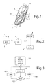
- Figure 1 shows a simplified and partially sectioned perspective view of a portable electronic device incorporating a pedometer according to the present invention;
- Figure 2 is a simplified block diagram of the pedometer of Figure 1;
- Figure 3 shows a flowchart corresponding to a control method according to the present invention executed by the pedometer of Figures 1 and 2;
- Figure 4 is a more detailed flowchart corresponding to a first step of the method of Figure 3;
- Figure 5 is a graph that represents first quantities used in the method according to the present invention;
- Figure 6 is a graph that represents second quantities used in the method according to the present invention;
- Figure 7 is a more detailed flowchart corresponding to a second step of the method of Figure 3; and
- Figure 8 is a more detailed flowchart corresponding to a third step of the method of Figure 3.
- With reference to Figures 1 and 2, a
pedometer 1 is integrated within a portable electronic device, such as acellphone 2. Thepedometer 1 comprises aninertial sensor 3, acontrol unit 5, equipped with a nonvolatile-memory module (not illustrated herein), adisplay 6, and acommunication interface 8, all housed on acard 9, which is, in turn, fixed within acasing 10 of thecellphone 2. In the embodiment described herein, thecontrol unit 5 performs control functions of thepedometer 1 and, moreover, presides over bi-directional communication and over handling of the functions envisaged for thecellphone 2. Likewise, thedisplay 6, which is obviously arranged so as to be visible from the outside of thecasing 10, can be used for displaying both information regarding thepedometer 1 and, more in general, information regarding the operation of thecellphone 2. - The
inertial sensor 3 is a linear accelerometer of a MEMS (micro-electromechanical systems) type and is mounted on thecard 9 so as to have a detection axis Z substantially parallel to a longitudinal axis L of thecasing 10 of thecellphone 2. In practice, the detection axis Z and the longitudinal axis L are substantially horizontal, when thecellphone 2 is resting on a surface, and substantially vertical or slightly inclined with respect to the vertical when thecellphone 2 is handled. Theinertial sensor 3 supplies at output an acceleration signal AZ, which is correlated to the accelerations undergone by theinertial sensor 3 itself along the detection axis Z. - The
control unit 5 receives and processes the acceleration signal AZ as explained in detail hereinafter for identifying and counting a total number of valid steps NVT made by a user wearing or carrying thepedometer 1, for example, on his belt or on his shoulder. In addition, thecontrol unit 5 is preferably configured for generating an estimate of the distance travelled by the user and other data, such as, for example, estimates of the average speed during movement and energy consumption. The total number of valid steps NVT and the other data possibly produced are sent to thedisplay 6. - The
communication interface 8 in this case is based on the transceiver system (known and not shown) of thecellphone 2 and, preferably, also comprises a port (also known and not shown) for communication with a computer. Thecommunication interface 8 can thus be used both for downloading the data produced by the pedometer 1 (amongst which at least the total number of valid steps NVT) and for uploading operating parameters for thepedometer 1 into thecontrol unit 5. - The
control unit 5 is configured for executing a control procedure, as illustrated with reference to Figures 3-8. - Upon switching-on of the
pedometer 1, an initialization step is executed (block 100, Figure 3), in which the total number of valid steps NVT, a second counter, hereinafter referred to as number of valid control steps NVC, and a third counter, hereinafter referred to as number of invalid steps NINV, are set to zero. - The
control unit 5 then executes a first counting procedure (block 110), based upon the sampling of the acceleration signal Az at a pre-determined frequency, for example 25 Hz. In this step, the user is considered at rest and thecontrol unit 5 is considered as waiting to recognize, on the basis of the acceleration signal AZ, sequences of events corresponding to a sequence of steps that are close to one another, which satisfy pre-determined conditions of regularity described in detail hereinafter. When a sequence of steps corresponding to a regular gait of the user is recognized, the first counting procedure is interrupted. Alternatively, the first counting procedure terminates when a time interval TC that has elapsed from the last step recognized is longer than a first time threshold TS1, for example 10 s. On exit from the first calculation procedure, thecontrol unit 5 sets a state flag FST to a first value C, if a sequence of steps that satisfies the conditions of regularity has been recognized, and to a second value PD, if the first time threshold TS1 has been exceeded. - At the end of the first counting procedure, the
control unit 5 checks whether the state flag FST has been set at the first value C (block 120), i.e., whether a sequence of steps has been recognized. If so (output YES from block 120), a second counting procedure is executed (block 130). The user is considered to be moving, and a first counter, hereinafter referred to as total number of valid steps NVT, is incremented whenever an event corresponding to a step is recognized. Furthermore, thecontrol unit 5 checks the regularity of the sequences of steps, as explained hereinafter, and, when an interruption in the locomotion is detected, the second counting procedure is terminated, and execution of the first counting procedure resumes (block 110). - If, instead, the state flag FST has the second value PD, the
pedometer 1 is set in a low-consumption wait state ("power down" state), and thecontrol unit 5 executes a surveying procedure (block 140). The surveying procedure terminates when a variation of the d.c. component of the acceleration signal AZ is detected, i.e., when thecellphone 2 that includes thepedometer 1 is moved. Thecontrol unit 5 then returns to execution of the first calculation procedure (block 110). - The first counting procedure is illustrated in greater detail in Figure 4.
- Initially, the
control unit 5 reads a sample of the acceleration signal AZ (block 200) and then evaluates whether the time interval TC that has elapsed from the last step recognized is higher than the first time threshold TS1, i.e., whether the step recognition fails for a period longer than the first time threshold TS1 (block 205). If so (output YES from block 205), the state flag FST is set at the second value PD (block 210) and the first counting procedure is terminated (in this eventuality, after the test on the state flag FST ofblock 120 of Figure 3, the surveying procedure is executed, block 140). Otherwise (output NO from block 205), the duration of the time interval TC is compared with a second time threshold TS2, shorter than the first time threshold TS1 and equal, for example, to 3 s (block 215). If the second time threshold TS2 has been exceeded (output YES from block 215), the number of valid control steps NVC and the number of invalid steps NINV are set to zero (block 220); then a step-recognition test is carried out (block 225). Otherwise (output NO from block 215), thecontrol unit 5 directly executes the step-recognition test. - In the step-recognition test of
block 225, thecontrol unit 5 verifies whether the time plot of the acceleration signal AZ (i.e., the sequence of the samples acquired) has pre-determined characteristics. In particular (Figure 5), a step is recognized if the acceleration signal AZ shows a positive peak, higher than a positive acceleration threshold AZP, followed by a negative peak, smaller than a negative acceleration threshold AZN, and if the negative peak falls within a time window TW of pre-determined amplitude and, moreover, located at a pre-determined distance after the positive peak. - If the
control unit 5 does not recognize an event corresponding to a step (output NO from block 225), a new sample of the acceleration signal AZ is read (block 200). If, instead, the step-recognition test is passed (output YES from block 225), thecontrol unit 5 executes a first validation test, corresponding to the regularity of the individual step (block 230). With reference also to Figure 6, the validation occurs when the duration ΔTK of a current step K is substantially homogeneous with respect to the duration ΔTK-1 of an immediately preceding step K-1 (the duration of a generic step is determined by the time that has elapsed between an instant of recognition of the step of which the duration is evaluated and an instant of recognition of the step that immediately precedes it). More precisely, the last step recognized is validated if the instant of recognition of the current step TR(K) falls within a validation interval TV, defined with respect to the instant of recognition of the immediately preceding step TR(K-1), in the following way:
where TA and TB are complementary portions of the validation interval TV. In the embodiment of the invention described herein, the complementary portions TA, TB are defined as follows, for the generic current step K:

- Consequently, the validation interval is asymmetrical with respect to the instant TC(K-1)+ΔTK-1 and has an amplitude equal to 3ΔTK-1/2. The validation interval TV could, however, be symmetrical and have a different amplitude. In practice, it is verified that the last step recognized is compatible with the frequency of the last steps made previously.
- If the verification yields a negative result (output NO from block 230), the number of invalid steps NINV is incremented by one (block 235) before being compared with a first programmable threshold number NT1, for example 3 (block 240). If the number of invalid steps NINV has reached the first threshold number NT1 (output YES from block 240), both the number of invalid steps NINV, and the number of valid control steps NVC are set to zero (block 245), and the first counting procedure is resumed, with reading of a new sample of the acceleration signal AZ (block 200). If, instead, the number of invalid steps NINV is smaller than the first threshold number NT1 (output NO from block 240), the number of valid control steps NVC is decremented (block 250). In the embodiment described herein, the decrement is equal to two. If the result of the decrement operation is negative, the number of valid control steps NVC is set to zero (in practice, the updated value of the number of valid control steps NVC is equal to the smaller between zero and the previous value of the number of valid control steps NVC, decreased by two). Then, the
control unit 5 reads a new sample of the acceleration signal AZ (block 200). - If the first validation test of
block 230 is passed, the number of valid control steps NVC is incremented by one (block 255), and then thecontrol unit 5 executes a first test on regularity of the sequence of steps recognized (block 260). The first regularity test is based upon a first condition of regularity and envisages comparing the number of valid control steps NVC with a second programmable threshold number NT2 greater than the first threshold number NT1 (for example, 8). In practice, the first condition of regularity is satisfied when there is a significant prevalence of steps spaced in a substantially uniform way, at the most interrupted sporadically by a number of irregular steps smaller than the first threshold number NT1. If the number of valid control steps NVC is smaller than the second threshold number NT2 (output NO from block 260), the first condition of regularity is not satisfied, and the first regularity test indicates that there has not yet been identified a sequence of steps corresponding to a sufficiently regular gait, and hence thecontrol unit 5 acquires once again a new sample of the acceleration signal AZ (block 200), without the total number of valid steps NVT being incremented. Otherwise (output YES from block 260), a sequence of steps is recognized that satisfies the first condition of regularity, and the first regularity test is passed. The number of invalid steps NINV and the number of valid control steps NVC are set to zero, whereas the total number of valid steps NVT is updated and incremented by a value equal to the second threshold number NT2 (block 265). Furthermore, the state flag FST is set at the count value, and the first counting procedure is terminated. In this case, after the test on the state flag ofblock 120 of Figure 3, the second counting procedure is executed (block 130). - In practice, the first counting procedure enables the
pedometer 1 to remain waiting for a sequence of events corresponding to a sequence of steps that satisfies the first condition of regularity. The regularity of the gait is considered sufficient when the number of valid control steps NVC reaches the second threshold number NT2. The events considered irregular or a waiting time that is too long between two successive steps cause the decrement (block 250) or the zeroization (blocks 220 and 245) of the number of valid control steps NVC, so that the first counting procedure resumes from the start. As long as thepedometer 1 is in the waiting condition, the total number of valid steps NVT is not incremented because the user is still considered as at rest. However, when the first regularity test (block 260) is passed, the total number of valid steps NVT is immediately updated so as to take into account the valid steps (equal to NT2) that make up the sequence considered as being regular. Isolated events and sequence of steps that are in any case too short are thus advantageously ignored, whereas counting of the steps promptly resumes also in the case of isolated irregularities (for example, due to a non-homogeneous acceleration or to a loss of balance at the start of locomotion). - The possibility of programming the value of the first threshold number NT1 and of the second threshold number NT2 enables modification of the sensitivity of the pedometer in recognizing an initial sequence of steps. For example, the user can program lower values of the first threshold number NT1 and of the second threshold number NT2 (for example 2 and 4, respectively) when he remains for a long time in a closed environment, for example an office or a room, where it would not in any case be possible to maintain a regular gait for a long time. In this way, shorter sequences of steps are validated and counted. Instead, during a more constant and intense activity, such as running, the gait remains constant for a long time, and hence the first threshold number NT1 and the second threshold number NT2 can be programmed with higher values (for example, 4 and 12, respectively). Step sequences that are shorter and not very significant in relation to the activity performed can be ignored.
- Figure 7 illustrates in detail the second counting procedure (executed in
block 130 of Figure 3). - The
control unit 5 initially reads a sample of the acceleration signal AZ (block 300), and then evaluates whether the time interval TC that has elapsed from the last step recognized is higher than the first second time threshold TS2 (block 305). If so (output YES from block 205), the number of invalid steps NINV and the number of valid control steps NVC are zeroized (block 310), and the second counting procedure is terminated. Otherwise (output NO from block 305), a step-recognition test is carried out (block 315), identical to the step-recognition test ofblock 225 of Figure 3. Also in this case, then, step recognition is based upon the detection of a positive peak of the acceleration signal AZ followed by a negative peak that falls in the time window TW (see Figure 5). - If the
control unit 5 does not recognize an event corresponding to a step (output NO from block 315), a new sample of the acceleration signal AZ is read (block 300). If, instead, the step-recognition test is passed (output YES from block 315), a second validation test is made, corresponding to the regularity of the individual step (block 320). The second validation test is altogether similar to the first validation test carried out inblock 230 of Figure 3. Also in this case, then, the last step recognized is validated if the instant of recognition of the current step TC(K) falls within the validation interval TV defined above. In practice, it is verified that the last step recognized is compatible with the frequency of the last steps made previously. - If the check yields a positive result (output YES from block 320), the
control unit 5 updates the total number of valid steps NVT and the number of valid control steps NVC, incrementing them by one (block 325). The number of valid control steps NVC is then compared with a third programmable threshold number NT3 (block 330), which, in the embodiment described herein, is equal to the second threshold number NT2. If the number of valid control steps NVC is smaller than the second threshold number NT2 (output NO from block 330), thecontrol unit 5 once again directly acquires a new sample of the acceleration signal AZ (block 300), whereas otherwise (output YES from block 330), the number of invalid steps NINV and the number of valid control steps NVC are set to zero (block 335) prior to acquisition of a new sample AZ. - If, instead, the second validation test of
block 320 is negative, the number of invalid steps NINV is incremented by one (block 340) before being compared with a fourth programmable threshold number NT4 (block 345), which, in the present embodiment, is equal to the first threshold number NT1. If the number of invalid steps NINV is smaller than the fourth threshold number NT4 (output NO from block 345), the number of valid control steps NVC is decremented (block 350), here by two. Also in this case, if the result of the decrement operation is negative, the number of valid control steps NVC is set to zero (the updated value of the number of valid control steps NVC is equal to the smaller between zero and the previous value of the number of valid control steps NVC, decreased by two). Then, thecontrol unit 5 reads a new sample of the acceleration signal AZ (block 300). If the number of invalid steps NINV has reached the fourth threshold number NT4 (output YES from block 345), the number of invalid steps NINV and the number of valid control steps NVC are set to zero (block 355), and the second counting procedure is terminated. - In practice, the second counting procedure is based on a second condition of regularity, which is satisfied as long as sporadic irregular steps occur within sequences of steps spaced in a substantially homogeneous way. More precisely, the second condition of regularity is satisfied as long as the number of invalid steps NINV is smaller than the fourth threshold number NT4. Consequently, the second counting procedure continues to update and increment the total number of valid steps NVT as long as the gait of the user is kept regular. Possible isolated irregularities are ignored and do not interrupt or suspend updating of the count, which is, instead, interrupted when prolonged pauses occur or in the presence of significant discontinuities in locomotion. However, if the gait becomes regular again, even with a different rhythm, also the count promptly resumes, because the first counting procedure is once again executed. This prevents a significant number of steps from being neglected.
- The surveying procedure executed in
block 140 of Figure 3 will now be described in greater detail, with reference to Figure 8. - When the surveying procedure is started, a current mean value AZM of the acceleration signal AZ is stored in the nonvolatile-memory module (not illustrated) of the control unit 5 (block 400). The current mean value AZM represents an estimate of the DC component of the acceleration signal AZ, which, when the
cellphone 2 containing thepedometer 1 is stationary, is determined substantially by the contribution of the acceleration of gravity along the detection axis Z. In practice, then, the current mean value AZM provides an estimate of the position of thecellphone 2 and of thepedometer 1. - After storage of the current mean value AZM, the
pedometer 1 is set in a low-consumption operating condition (power-down condition), in which at least theinertial sensor 3 is inactive (block 410). - A waiting cycle is then carried out (block 420), for example of the duration of 10 s, after which all the functions of the
pedometer 1 are re-activated ("power on", block 430). - The
control unit 5 acquires from the inertial sensor 3 a number of samples of the acceleration signal AZ sufficient for estimating an updated mean value AZM' (block 440), which is then compared with the current mean value AZM previously stored (block 450). - If the updated mean value AZM' departs from the current mean value AZM (output NO from block 450), the surveying procedure is interrupted, and the first counting procedure indicated in
block 110 of Figure 3 is executed. If, instead, the updated mean value AZM' is substantially unvaried with respect to the current mean value AZM (output YES from block 450), the surveying procedure proceeds and thepedometer 1 is set again in the low-consumption operating condition (block 410). - Clearly, the use of the surveying procedure enables a drastic reduction in the power consumption when the
pedometer 1 is not used and, hence increases the autonomy thereof. If, as in the embodiment described, thepedometer 1 is integrated in a portable device with which it shares the use of resources, for example thecontrol unit 5, the surveying procedure entails further advantages. In fact, the de-activation of the functions linked to thepedometer 1 frees the shared resources for use by the active functions, which can thus access the resources themselves in a more efficient way. - Finally, it is evident that modifications and variations can be made to the device described herein, without thereby departing from the scope of the present invention, as defined in the annexed claims.
- In particular, the control procedure described can be used to advantage in a stand-alone pedometer or in any case one integrated in a further portable device, but with stand-alone and non-shared resources.
- Furthermore, the conditions of regularity used to enable or prevent counting of the steps recognized can be different from the ones described. For example, a sequence of steps can be considered regular when possible steps recognized and not validated are separated by at least one pre-determined number of consecutive validated steps. Again, a sequence of a pre-determined number of validated or non-validated steps (sequence of fixed length) can be considered regular when the validated steps are at least a given percentage of the steps of the sequence.
- Finally, the inertial sensor can be of the type with two or three axes of detection. In this case, step recognition can advantageously be performed by selecting the acceleration signal corresponding to the detection axis nearest to the vertical. The nearer the detection axis used is to the vertical, in fact, the greater the amplitude of the signal useful for step recognition. The detection axis is selected on the basis of the value of the DC component of the respective acceleration signal, which is correlated to the contribution of the acceleration of gravity. The detection axis nearest to the vertical is the axis along which the contribution of the acceleration of gravity is greater. The pedometer can then be used independently of how it is oriented.
Claims (15)
- A method for controlling a pedometer comprising the steps of:- generating a signal (AZ) correlated to movements of a user of the pedometer; and- detecting steps (200-225, 300-320) of the user on the basis of said signal (AZ) ;
said method being characterized in that it comprises the steps of:- checking whether sequences of detected steps (K-2, K-1, K) satisfy pre-determined conditions of regularity (230, 320, 345);- updating a total number of valid steps (NVT, 265, 325, 350) if said conditions of regularity (230, 320, 345) are satisfied; and- preventing updating of said total number of valid steps (NVT) if said conditions of regularity (230, 320, 345) are not satisfied. - The method according to Claim 1, wherein said step of checking whether sequences of steps detected (K-2, K-1, K) satisfy pre-determined conditions of regularity (230, 320, 345) comprises:- in a first operating condition (110), checking whether a first condition of regularity (230) is satisfied; and- in a second operating condition (130), checking whether a second condition of regularity is satisfied (345).
- The method according to Claim 2, wherein, during said step of checking whether said first condition of regularity (230) is satisfied, the updating of said total number of valid steps (NVT) is prevented.
- The method according to Claim 2 or Claim 3, wherein, during said step of checking whether said second condition of regularity (345) is satisfied, the updating of said total number of valid steps (NVT) is allowed.
- The method according to Claim 3, wherein said step of checking whether said first condition of regularity (230) is satisfied comprises:- carrying out a first validation test (230) of a current detected step (K);- incrementing a number of valid control steps (NVC) if on the basis of said first validation test (230) said current detected step (K) is validated (255) ; and- incrementing a number of invalid steps (NINV) and decrementing said number of valid control steps (NVC) if on the basis of said first validation test (230) said current detected step (K) is not validated (255).
- The method according to Claim 5, wherein said step of executing said first validation test (230) of said current detected step (K) comprises evaluating whether a first duration (ΔTK) of said current detected step (K) is homogeneous with respect to a second duration (ΔTK-1) of an immediately preceding detected step (K-1).
- The method according to Claim 6, wherein said first validation test (230) yields a positive result when an instant of recognition of the current step TR(K) falls within a validation interval (TV), defined with respect to an instant of recognition of the immediately preceding step TR(K-1), in the following way:

where ΔTK-1 is said second duration, and TA and TB are complementary portions of said validation interval (TV). - The method according to any one of Claims 5-7, wherein said step of checking whether said first condition of regularity (230) is satisfied comprises comparing said number of invalid steps (NINV) with a first threshold number (NT1) and comparing said number of valid control steps (NVC) with a second threshold number (NT2).
- The method according to Claim 8, wherein said first condition of regularity (230) is satisfied if said number of valid control steps (NVC) is equal to said second threshold number (NT2).
- The method according to any one of Claims 4-9, wherein said step of checking whether said second condition of regularity (345) is satisfied comprises:- executing a second validation test (320) of said current detected step (K);- incrementing said number of valid control steps (NVC) and said total number of valid steps (NVT) if on the basis of said second validation test (320) said current detected step (K) is validated (325); and- incrementing a number of invalid steps (NINV) if on the basis of said second validation test (320) said current detected step (K) is not validated (340).
- The method according to Claim 10, wherein said step of checking whether said second condition of regularity (345) is satisfied comprises comparing said number of valid control steps (NVC) with a third threshold number (NT3) and comparing said number of invalid steps (NINV) with a fourth threshold number (NT4).
- The method according to Claim 11, wherein said second condition of regularity (345) is satisfied if said number of invalid steps (NINV) is smaller than said fourth threshold number (NT4).
- The method according to Claim 12, comprising the step of incrementing said total number of valid steps (NVT) and decrementing said number of valid control steps (NVC) if, on the basis of said second validation test (320), said current detected step (K) is not validated (340) and said number of invalid steps (NINV) is smaller than said fourth threshold number (NT4).
- The method according to any one of the preceding claims, comprising the step of setting said pedometer (1) in a third operating condition (140), wherein said pedometer (1) is at least partially de-activated, if said step of detecting steps (200-225) of the user on the basis of said signal (AZ) fails for a period longer than a pre-set time threshold (TS1).
- A pedometer comprising an inertial sensor (3) and a control unit (5) associated to said inertial sensor (3), characterized in that said control unit (5) is configured for executing a control method according to any one of Claims 1-14.
Priority Applications (3)
| Application Number | Priority Date | Filing Date | Title |
|---|---|---|---|
| EP05425684A EP1770369B1 (en) | 2005-10-03 | 2005-10-03 | A method for controlling a pedometer. |
| US11/537,986 US7698097B2 (en) | 2005-10-03 | 2006-10-02 | Method for controlling a pedometer based on the use of inertial sensors and pedometer implementing the method |
| JP2006272099A JP5095975B2 (en) | 2005-10-03 | 2006-10-03 | Pedometer control method based on use of inertial sensor and pedometer implementing the method |
Applications Claiming Priority (1)
| Application Number | Priority Date | Filing Date | Title |
|---|---|---|---|
| EP05425684A EP1770369B1 (en) | 2005-10-03 | 2005-10-03 | A method for controlling a pedometer. |
Publications (2)
| Publication Number | Publication Date |
|---|---|
| EP1770369A1 true EP1770369A1 (en) | 2007-04-04 |
| EP1770369B1 EP1770369B1 (en) | 2012-06-06 |
Family
ID=36118173
Family Applications (1)
| Application Number | Title | Priority Date | Filing Date |
|---|---|---|---|
| EP05425684A Expired - Lifetime EP1770369B1 (en) | 2005-10-03 | 2005-10-03 | A method for controlling a pedometer. |
Country Status (3)
| Country | Link |
|---|---|
| US (1) | US7698097B2 (en) |
| EP (1) | EP1770369B1 (en) |
| JP (1) | JP5095975B2 (en) |
Cited By (5)
| Publication number | Priority date | Publication date | Assignee | Title |
|---|---|---|---|---|
| CN103096796A (en) * | 2010-03-25 | 2013-05-08 | 欧姆龙健康医疗事业株式会社 | Activity meter, manufacturing method thereof, and storage medium |
| WO2016003887A1 (en) * | 2014-06-30 | 2016-01-07 | Garmin Switzerland Gmbh | Automatic reset of physical performance information |
| WO2018086321A1 (en) * | 2016-11-11 | 2018-05-17 | 华为技术有限公司 | Step counting method and device |
| CN111765900A (en) * | 2020-07-30 | 2020-10-13 | 歌尔科技有限公司 | Step counting method, step counting device and computer readable storage medium |
| IT201900016142A1 (en) | 2019-09-12 | 2021-03-12 | St Microelectronics Srl | DOUBLE VALIDATION STEP DETECTION SYSTEM AND METHOD |
Families Citing this family (11)
| Publication number | Priority date | Publication date | Assignee | Title |
|---|---|---|---|---|
| EP1770368B1 (en) * | 2005-10-03 | 2009-05-27 | STMicroelectronics S.r.l. | Pedometer device and step detection method using an algorithm for self-adaptive computation of acceleration thresholds. |
| EP1813916B1 (en) * | 2006-01-30 | 2014-04-30 | STMicroelectronics Srl | Inertial device with pedometer function and portable electronic appliance incorporating said inertial device |
| JP5416896B2 (en) * | 2007-11-15 | 2014-02-12 | シチズン・システムズ株式会社 | Body motion detection device |
| CN102106138A (en) * | 2008-07-29 | 2011-06-22 | 京瓷株式会社 | Portable electronic device |
| WO2010073689A1 (en) * | 2008-12-26 | 2010-07-01 | オムロンヘルスケア株式会社 | Electronic sphygmomanometer, and method of measurement of blood pressure |
| WO2013169755A2 (en) * | 2012-05-07 | 2013-11-14 | Wimm Labs, Inc. | Pedometer in a low-power device |
| JP6056045B2 (en) * | 2012-10-17 | 2017-01-11 | 株式会社タニタ | Pedometer and sensitivity adjustment method |
| US9797743B2 (en) * | 2012-11-01 | 2017-10-24 | Verizon Telematics Inc. | Method and system for determining whether to reset a height in a height determining device based on the occurrence of steps |
| FR3016030B1 (en) * | 2013-12-31 | 2016-11-04 | Commissariat Energie Atomique | METHOD AND DEVICE FOR COUNTING PASTE |
| US10598510B2 (en) | 2014-11-27 | 2020-03-24 | Razer (Asia-Pacific) Pte. Ltd. | Step counter devices and step counting methods |
| US11112268B2 (en) * | 2017-08-28 | 2021-09-07 | Stmicroelectronics S.R.L. | Electronic device for performing step counting with false-positive rejection |
Citations (4)
| Publication number | Priority date | Publication date | Assignee | Title |
|---|---|---|---|---|
| JPS63262784A (en) * | 1987-04-20 | 1988-10-31 | Matsushita Electric Works Ltd | Electronic pedometer |
| JPH04192095A (en) * | 1990-11-27 | 1992-07-10 | Matsushita Electric Works Ltd | Pedometer |
| GB2359890A (en) * | 2000-03-01 | 2001-09-05 | Spinnaker Int Ltd | Electronic pedometer, expected behaviour detector and security system |
| US6898550B1 (en) * | 1997-10-02 | 2005-05-24 | Fitsense Technology, Inc. | Monitoring activity of a user in locomotion on foot |
Family Cites Families (5)
| Publication number | Priority date | Publication date | Assignee | Title |
|---|---|---|---|---|
| US6175608B1 (en) * | 1998-10-28 | 2001-01-16 | Knowmo Llc | Pedometer |
| JP2001297318A (en) * | 2000-04-14 | 2001-10-26 | Omron Corp | Pedometer |
| JP4785348B2 (en) * | 2004-04-20 | 2011-10-05 | セイコーインスツル株式会社 | Electronic pedometer |
| JP4785349B2 (en) * | 2004-04-20 | 2011-10-05 | セイコーインスツル株式会社 | Electronic pedometer |
| JP2006227911A (en) * | 2005-02-17 | 2006-08-31 | Citizen Watch Co Ltd | Pedometer, step counting method and step counting program |
-
2005
- 2005-10-03 EP EP05425684A patent/EP1770369B1/en not_active Expired - Lifetime
-
2006
- 2006-10-02 US US11/537,986 patent/US7698097B2/en active Active
- 2006-10-03 JP JP2006272099A patent/JP5095975B2/en active Active
Patent Citations (4)
| Publication number | Priority date | Publication date | Assignee | Title |
|---|---|---|---|---|
| JPS63262784A (en) * | 1987-04-20 | 1988-10-31 | Matsushita Electric Works Ltd | Electronic pedometer |
| JPH04192095A (en) * | 1990-11-27 | 1992-07-10 | Matsushita Electric Works Ltd | Pedometer |
| US6898550B1 (en) * | 1997-10-02 | 2005-05-24 | Fitsense Technology, Inc. | Monitoring activity of a user in locomotion on foot |
| GB2359890A (en) * | 2000-03-01 | 2001-09-05 | Spinnaker Int Ltd | Electronic pedometer, expected behaviour detector and security system |
Non-Patent Citations (2)
| Title |
|---|
| PATENT ABSTRACTS OF JAPAN vol. 013, no. 080 (P - 832) 23 February 1989 (1989-02-23) * |
| PATENT ABSTRACTS OF JAPAN vol. 016, no. 520 (P - 1444) 26 October 1992 (1992-10-26) * |
Cited By (8)
| Publication number | Priority date | Publication date | Assignee | Title |
|---|---|---|---|---|
| CN103096796A (en) * | 2010-03-25 | 2013-05-08 | 欧姆龙健康医疗事业株式会社 | Activity meter, manufacturing method thereof, and storage medium |
| WO2016003887A1 (en) * | 2014-06-30 | 2016-01-07 | Garmin Switzerland Gmbh | Automatic reset of physical performance information |
| WO2018086321A1 (en) * | 2016-11-11 | 2018-05-17 | 华为技术有限公司 | Step counting method and device |
| IT201900016142A1 (en) | 2019-09-12 | 2021-03-12 | St Microelectronics Srl | DOUBLE VALIDATION STEP DETECTION SYSTEM AND METHOD |
| EP3791787A1 (en) | 2019-09-12 | 2021-03-17 | STMicroelectronics S.r.l. | System and method for detecting steps with double validation |
| US11598649B2 (en) | 2019-09-12 | 2023-03-07 | Stmicroelectronics S.R.L. | System and method for detecting steps with double validation |
| CN111765900A (en) * | 2020-07-30 | 2020-10-13 | 歌尔科技有限公司 | Step counting method, step counting device and computer readable storage medium |
| CN111765900B (en) * | 2020-07-30 | 2022-02-22 | 歌尔科技有限公司 | Step counting method, step counting device and computer readable storage medium |
Also Published As
| Publication number | Publication date |
|---|---|
| EP1770369B1 (en) | 2012-06-06 |
| JP5095975B2 (en) | 2012-12-12 |
| US7698097B2 (en) | 2010-04-13 |
| JP2007115243A (en) | 2007-05-10 |
| US20070143069A1 (en) | 2007-06-21 |
Similar Documents
| Publication | Publication Date | Title |
|---|---|---|
| EP1770369B1 (en) | A method for controlling a pedometer. | |
| US8949070B1 (en) | Human activity monitoring device with activity identification | |
| US7450002B2 (en) | Method and apparatus for monitoring human activity pattern | |
| CN102168986B (en) | Stride estimation method, method of calculating movement trajectory and stride estimating unit | |
| US8712723B1 (en) | Human activity monitoring device | |
| JP5059368B2 (en) | Pedometer apparatus and step detection method using algorithm of self-adaptive calculation of acceleration threshold | |
| JP4898514B2 (en) | Pedometer | |
| JP4785526B2 (en) | Electronic pedometer | |
| KR100800874B1 (en) | Stride length estimation method and portable terminal for same | |
| JP4785348B2 (en) | Electronic pedometer | |
| RU2711468C2 (en) | Electronic mobile device | |
| US8674946B2 (en) | Method and apparatus for controlling timing of status change of electronics apparatus based on user's finger location and input speed | |
| JP4785349B2 (en) | Electronic pedometer | |
| EP2997898B1 (en) | Electronic device, control program, control method, and system | |
| CN103096796A (en) | Activity meter, manufacturing method thereof, and storage medium | |
| US20070030159A1 (en) | Method and apparatus for detecting free fall of mobile device and recording medium storing computer program for executing the method | |
| JP5032874B2 (en) | Pedometer | |
| JP4885676B2 (en) | Pedometer | |
| JP4706310B2 (en) | Pedometer | |
| JP2013196442A (en) | Step count measuring device | |
| CN107735024B (en) | Action notification system, exercise information measuring device, electronic device, action notification method, recording medium | |
| CN113961062B (en) | Information processing device, information processing method and storage medium | |
| JP5032875B2 (en) | Pedometer | |
| US20170289649A1 (en) | Sensing Device and Corresponding Apparatus and Method | |
| JP2014045325A (en) | State detection device, state detection method, and program |
Legal Events
| Date | Code | Title | Description |
|---|---|---|---|
| PUAI | Public reference made under article 153(3) epc to a published international application that has entered the european phase |
Free format text: ORIGINAL CODE: 0009012 |
|
| AK | Designated contracting states |
Kind code of ref document: A1 Designated state(s): AT BE BG CH CY CZ DE DK EE ES FI FR GB GR HU IE IS IT LI LT LU LV MC NL PL PT RO SE SI SK TR |
|
| AX | Request for extension of the european patent |
Extension state: AL BA HR MK YU |
|
| 17P | Request for examination filed |
Effective date: 20071003 |
|
| 17Q | First examination report despatched |
Effective date: 20071102 |
|
| AKX | Designation fees paid |
Designated state(s): DE FR GB IT |
|
| RAP1 | Party data changed (applicant data changed or rights of an application transferred) |
Owner name: STMICROELECTRONICS SRL |
|
| GRAP | Despatch of communication of intention to grant a patent |
Free format text: ORIGINAL CODE: EPIDOSNIGR1 |
|
| GRAS | Grant fee paid |
Free format text: ORIGINAL CODE: EPIDOSNIGR3 |
|
| GRAA | (expected) grant |
Free format text: ORIGINAL CODE: 0009210 |
|
| RAP1 | Party data changed (applicant data changed or rights of an application transferred) |
Owner name: STMICROELECTRONICS SRL |
|
| AK | Designated contracting states |
Kind code of ref document: B1 Designated state(s): DE FR GB IT |
|
| REG | Reference to a national code |
Ref country code: GB Ref legal event code: FG4D |
|
| REG | Reference to a national code |
Ref legal event code: R082 Country of ref document: DE Ref country code: DE Ref document number: 602005034522 Representative=s name: SCHMITT-NILSON SCHRAUD WAIBEL WOHLFROM PATENTA, DE |
|
| REG | Reference to a national code |
Ref country code: DE Ref legal event code: R096 Ref document number: 602005034522 Country of ref document: DE Effective date: 20120809 |
|
| PLBE | No opposition filed within time limit |
Free format text: ORIGINAL CODE: 0009261 |
|
| STAA | Information on the status of an ep patent application or granted ep patent |
Free format text: STATUS: NO OPPOSITION FILED WITHIN TIME LIMIT |
|
| 26N | No opposition filed |
Effective date: 20130307 |
|
| GBPC | Gb: european patent ceased through non-payment of renewal fee |
Effective date: 20121003 |
|
| REG | Reference to a national code |
Ref country code: DE Ref legal event code: R097 Ref document number: 602005034522 Country of ref document: DE Effective date: 20130307 |
|
| REG | Reference to a national code |
Ref country code: FR Ref legal event code: ST Effective date: 20130628 |
|
| PG25 | Lapsed in a contracting state [announced via postgrant information from national office to epo] |
Ref country code: GB Free format text: LAPSE BECAUSE OF NON-PAYMENT OF DUE FEES Effective date: 20121003 |
|
| PG25 | Lapsed in a contracting state [announced via postgrant information from national office to epo] |
Ref country code: FR Free format text: LAPSE BECAUSE OF NON-PAYMENT OF DUE FEES Effective date: 20121031 |
|
| REG | Reference to a national code |
Ref country code: DE Ref legal event code: R082 Ref document number: 602005034522 Country of ref document: DE Representative=s name: SCHMITT-NILSON SCHRAUD WAIBEL WOHLFROM PATENTA, DE |
|
| PGFP | Annual fee paid to national office [announced via postgrant information from national office to epo] |
Ref country code: IT Payment date: 20190918 Year of fee payment: 15 |
|
| PG25 | Lapsed in a contracting state [announced via postgrant information from national office to epo] |
Ref country code: IT Free format text: LAPSE BECAUSE OF NON-PAYMENT OF DUE FEES Effective date: 20201003 |
|
| PGFP | Annual fee paid to national office [announced via postgrant information from national office to epo] |
Ref country code: DE Payment date: 20240919 Year of fee payment: 20 |
|
| REG | Reference to a national code |
Ref country code: DE Ref legal event code: R071 Ref document number: 602005034522 Country of ref document: DE |