EP1770344A2 - Foam core heat exchanger and method - Google Patents
Foam core heat exchanger and method Download PDFInfo
- Publication number
- EP1770344A2 EP1770344A2 EP06255076A EP06255076A EP1770344A2 EP 1770344 A2 EP1770344 A2 EP 1770344A2 EP 06255076 A EP06255076 A EP 06255076A EP 06255076 A EP06255076 A EP 06255076A EP 1770344 A2 EP1770344 A2 EP 1770344A2
- Authority
- EP
- European Patent Office
- Prior art keywords
- flexible
- heat
- heat exchanger
- spiralling
- assembly
- Prior art date
- Legal status (The legal status is an assumption and is not a legal conclusion. Google has not performed a legal analysis and makes no representation as to the accuracy of the status listed.)
- Withdrawn
Links
- 238000000034 method Methods 0.000 title claims abstract description 20
- 239000006260 foam Substances 0.000 title claims description 14
- 239000004020 conductor Substances 0.000 claims abstract description 10
- 238000010438 heat treatment Methods 0.000 claims abstract description 10
- 238000007493 shaping process Methods 0.000 claims abstract description 8
- 238000004519 manufacturing process Methods 0.000 claims abstract description 3
- 239000000463 material Substances 0.000 claims description 56
- 239000012530 fluid Substances 0.000 claims description 38
- 239000011148 porous material Substances 0.000 claims description 38
- 125000006850 spacer group Chemical group 0.000 claims description 20
- PXHVJJICTQNCMI-UHFFFAOYSA-N Nickel Chemical compound [Ni] PXHVJJICTQNCMI-UHFFFAOYSA-N 0.000 claims description 8
- 229910000990 Ni alloy Inorganic materials 0.000 claims description 6
- 238000005096 rolling process Methods 0.000 claims description 6
- 238000005245 sintering Methods 0.000 claims description 6
- 229910045601 alloy Inorganic materials 0.000 claims description 5
- 239000000956 alloy Substances 0.000 claims description 5
- 239000006262 metallic foam Substances 0.000 claims description 4
- 229910052759 nickel Inorganic materials 0.000 claims description 4
- 239000000843 powder Substances 0.000 claims description 4
- 239000011888 foil Substances 0.000 description 43
- 239000007788 liquid Substances 0.000 description 12
- 239000000446 fuel Substances 0.000 description 9
- 239000002184 metal Substances 0.000 description 7
- 229910052751 metal Inorganic materials 0.000 description 7
- 239000006261 foam material Substances 0.000 description 5
- 238000007789 sealing Methods 0.000 description 3
- 238000010276 construction Methods 0.000 description 2
- 238000012986 modification Methods 0.000 description 2
- 230000004048 modification Effects 0.000 description 2
- 230000000712 assembly Effects 0.000 description 1
- 238000000429 assembly Methods 0.000 description 1
- 238000005219 brazing Methods 0.000 description 1
- 238000001816 cooling Methods 0.000 description 1
- NPURPEXKKDAKIH-UHFFFAOYSA-N iodoimino(oxo)methane Chemical compound IN=C=O NPURPEXKKDAKIH-UHFFFAOYSA-N 0.000 description 1
- 239000002923 metal particle Substances 0.000 description 1
- 150000002739 metals Chemical class 0.000 description 1
- 230000000979 retarding effect Effects 0.000 description 1
Images

Classifications
-
- B—PERFORMING OPERATIONS; TRANSPORTING
- B22—CASTING; POWDER METALLURGY
- B22F—WORKING METALLIC POWDER; MANUFACTURE OF ARTICLES FROM METALLIC POWDER; MAKING METALLIC POWDER; APPARATUS OR DEVICES SPECIALLY ADAPTED FOR METALLIC POWDER
- B22F7/00—Manufacture of composite layers, workpieces, or articles, comprising metallic powder, by sintering the powder, with or without compacting wherein at least one part is obtained by sintering or compression
- B22F7/002—Manufacture of composite layers, workpieces, or articles, comprising metallic powder, by sintering the powder, with or without compacting wherein at least one part is obtained by sintering or compression of porous nature
- B22F7/004—Manufacture of composite layers, workpieces, or articles, comprising metallic powder, by sintering the powder, with or without compacting wherein at least one part is obtained by sintering or compression of porous nature comprising at least one non-porous part
-
- F—MECHANICAL ENGINEERING; LIGHTING; HEATING; WEAPONS; BLASTING
- F28—HEAT EXCHANGE IN GENERAL
- F28D—HEAT-EXCHANGE APPARATUS, NOT PROVIDED FOR IN ANOTHER SUBCLASS, IN WHICH THE HEAT-EXCHANGE MEDIA DO NOT COME INTO DIRECT CONTACT
- F28D7/00—Heat-exchange apparatus having stationary tubular conduit assemblies for both heat-exchange media, the media being in contact with different sides of a conduit wall
- F28D7/04—Heat-exchange apparatus having stationary tubular conduit assemblies for both heat-exchange media, the media being in contact with different sides of a conduit wall the conduits being spirally coiled
-
- F—MECHANICAL ENGINEERING; LIGHTING; HEATING; WEAPONS; BLASTING
- F28—HEAT EXCHANGE IN GENERAL
- F28D—HEAT-EXCHANGE APPARATUS, NOT PROVIDED FOR IN ANOTHER SUBCLASS, IN WHICH THE HEAT-EXCHANGE MEDIA DO NOT COME INTO DIRECT CONTACT
- F28D9/00—Heat-exchange apparatus having stationary plate-like or laminated conduit assemblies for both heat-exchange media, the media being in contact with different sides of a conduit wall
- F28D9/04—Heat-exchange apparatus having stationary plate-like or laminated conduit assemblies for both heat-exchange media, the media being in contact with different sides of a conduit wall the conduits being formed by spirally-wound plates or laminae
-
- F—MECHANICAL ENGINEERING; LIGHTING; HEATING; WEAPONS; BLASTING
- F28—HEAT EXCHANGE IN GENERAL
- F28F—DETAILS OF HEAT-EXCHANGE AND HEAT-TRANSFER APPARATUS, OF GENERAL APPLICATION
- F28F13/00—Arrangements for modifying heat-transfer, e.g. increasing, decreasing
- F28F13/003—Arrangements for modifying heat-transfer, e.g. increasing, decreasing by using permeable mass, perforated or porous materials
-
- F—MECHANICAL ENGINEERING; LIGHTING; HEATING; WEAPONS; BLASTING
- F28—HEAT EXCHANGE IN GENERAL
- F28F—DETAILS OF HEAT-EXCHANGE AND HEAT-TRANSFER APPARATUS, OF GENERAL APPLICATION
- F28F21/00—Constructions of heat-exchange apparatus characterised by the selection of particular materials
- F28F21/08—Constructions of heat-exchange apparatus characterised by the selection of particular materials of metal
- F28F21/081—Heat exchange elements made from metals or metal alloys
- F28F21/087—Heat exchange elements made from metals or metal alloys from nickel or nickel alloys
-
- B—PERFORMING OPERATIONS; TRANSPORTING
- B22—CASTING; POWDER METALLURGY
- B22F—WORKING METALLIC POWDER; MANUFACTURE OF ARTICLES FROM METALLIC POWDER; MAKING METALLIC POWDER; APPARATUS OR DEVICES SPECIALLY ADAPTED FOR METALLIC POWDER
- B22F2998/00—Supplementary information concerning processes or compositions relating to powder metallurgy
-
- F—MECHANICAL ENGINEERING; LIGHTING; HEATING; WEAPONS; BLASTING
- F28—HEAT EXCHANGE IN GENERAL
- F28F—DETAILS OF HEAT-EXCHANGE AND HEAT-TRANSFER APPARATUS, OF GENERAL APPLICATION
- F28F2255/00—Heat exchanger elements made of materials having special features or resulting from particular manufacturing processes
- F28F2255/18—Heat exchanger elements made of materials having special features or resulting from particular manufacturing processes sintered
-
- F—MECHANICAL ENGINEERING; LIGHTING; HEATING; WEAPONS; BLASTING
- F28—HEAT EXCHANGE IN GENERAL
- F28F—DETAILS OF HEAT-EXCHANGE AND HEAT-TRANSFER APPARATUS, OF GENERAL APPLICATION
- F28F2265/00—Safety or protection arrangements; Arrangements for preventing malfunction
- F28F2265/16—Safety or protection arrangements; Arrangements for preventing malfunction for preventing leakage
-
- Y—GENERAL TAGGING OF NEW TECHNOLOGICAL DEVELOPMENTS; GENERAL TAGGING OF CROSS-SECTIONAL TECHNOLOGIES SPANNING OVER SEVERAL SECTIONS OF THE IPC; TECHNICAL SUBJECTS COVERED BY FORMER USPC CROSS-REFERENCE ART COLLECTIONS [XRACs] AND DIGESTS
- Y10—TECHNICAL SUBJECTS COVERED BY FORMER USPC
- Y10T—TECHNICAL SUBJECTS COVERED BY FORMER US CLASSIFICATION
- Y10T29/00—Metal working
- Y10T29/49—Method of mechanical manufacture
- Y10T29/4935—Heat exchanger or boiler making
-
- Y—GENERAL TAGGING OF NEW TECHNOLOGICAL DEVELOPMENTS; GENERAL TAGGING OF CROSS-SECTIONAL TECHNOLOGIES SPANNING OVER SEVERAL SECTIONS OF THE IPC; TECHNICAL SUBJECTS COVERED BY FORMER USPC CROSS-REFERENCE ART COLLECTIONS [XRACs] AND DIGESTS
- Y10—TECHNICAL SUBJECTS COVERED BY FORMER USPC
- Y10T—TECHNICAL SUBJECTS COVERED BY FORMER US CLASSIFICATION
- Y10T29/00—Metal working
- Y10T29/49—Method of mechanical manufacture
- Y10T29/4935—Heat exchanger or boiler making
- Y10T29/49357—Regenerator or recuperator making
-
- Y—GENERAL TAGGING OF NEW TECHNOLOGICAL DEVELOPMENTS; GENERAL TAGGING OF CROSS-SECTIONAL TECHNOLOGIES SPANNING OVER SEVERAL SECTIONS OF THE IPC; TECHNICAL SUBJECTS COVERED BY FORMER USPC CROSS-REFERENCE ART COLLECTIONS [XRACs] AND DIGESTS
- Y10—TECHNICAL SUBJECTS COVERED BY FORMER USPC
- Y10T—TECHNICAL SUBJECTS COVERED BY FORMER US CLASSIFICATION
- Y10T29/00—Metal working
- Y10T29/49—Method of mechanical manufacture
- Y10T29/4935—Heat exchanger or boiler making
- Y10T29/49366—Sheet joined to sheet
-
- Y—GENERAL TAGGING OF NEW TECHNOLOGICAL DEVELOPMENTS; GENERAL TAGGING OF CROSS-SECTIONAL TECHNOLOGIES SPANNING OVER SEVERAL SECTIONS OF THE IPC; TECHNICAL SUBJECTS COVERED BY FORMER USPC CROSS-REFERENCE ART COLLECTIONS [XRACs] AND DIGESTS
- Y10—TECHNICAL SUBJECTS COVERED BY FORMER USPC
- Y10T—TECHNICAL SUBJECTS COVERED BY FORMER US CLASSIFICATION
- Y10T29/00—Metal working
- Y10T29/49—Method of mechanical manufacture
- Y10T29/4935—Heat exchanger or boiler making
- Y10T29/49366—Sheet joined to sheet
- Y10T29/49369—Utilizing bond inhibiting material
Definitions
- the invention relates generally to heat exchangers and, more particularly, to an improved foam core heat exchanger and related method of construction thereof.
- Heat exchangers performing heat exchange between two fluids have been known to use porous foamed metal fins to augment the heat transfer area to volume ratio on the gas side of the heat exchanger.
- Such fins are usually molded by solidifying molten metal in separate molds or directly in cavities formed by rigid components of the heat exchanger.
- the heat exchanger or heat sink usually has a rigid structure which cannot be easily manipulated to conform to a desired shape.
- Heat exchangers in a gas turbine engine need to occupy a minimal volume and include conduits with a small cross-section which can resist considerably high temperatures and pressures while remaining lightweight.
- Spiral heat exchangers are known to occupy a minimal volume and are usually formed by rolling two long sheets of metal around a common axis. However, maintaining a small gap between adjacent layers of the spiral to obtain small cross-section conduits is usually very complex. In addition, such rollable spaced apart sheets of metals are usually not adapted to resist to considerably high pressures.
- heat exchangers having high temperature and pressure capabilities include superposed, parallel rigid plates connected by intermediate walls.
- Such a construction while strong, is usually difficult to adapt to a spiral geometry in order to make most effective use of the space occupied by the heat exchanger.
- the present invention provides a method of forming a heat exchanger comprising the steps of: forming a flexible heat exchanging assembly by: laying a first flexible sheet composed of heat conducting impermeable material on a support surface; laying a second flexible sheet composed of heat conducting impermeable material in a spaced apart manner over the first flexible sheet to define at least one elongated conduit for a first fluid flow between the first and second flexible sheets; and laying a third flexible sheet composed of flexible heat conducting foam on the second flexible sheet, the heat conducting foam having a plurality of interconnected pores defining a passage therethrough for a second fluid flow; shaping the flexible heat exchanging assembly into a desired shape; and bonding the flexible heat exchanging assembly together to form a rigid heat exchanger, the at least one conduit and the passage extending in a superposed manner throughout the heat exchanger in heat exchange relationship with one another.
- the present invention provides a spiral heat exchanger comprising: at least one first spiralling conduit for directing a first fluid flow, the at least one first spiralling conduit extending between two pairs of opposed, spiralling sealed surfaces to define first and second open ends, the first open end being located near an outer circumference of the spiral heat exchanger, the second open end being located near a core of the spiral heat exchanger; a second spiralling conduit for directing a second fluid flow, the second conduit being adjacent the at least one first spiralling conduit and in heat exchange relationship therewith, the second spiralling conduit extending between two pairs of opposed, spiralling sealed surfaces to define third and fourth open ends, the third open end being located near the outer circumference, the fourth open end being located near the core, the second spiralling conduit including therein a heat conducting porous material permitting the second fluid flow to circulate therethrough.
- the present invention provides a method for manufacturing a heat exchanger, the method comprising: forming at least one flexible heat exchanging assembly composed of flexible heat conducting material and having at least first and second adjacent conduits defined therein in heat exchange relationship with one another; shaping the at least one flexible heat exchanging assembly to a desired heat exchanger shape; and heating the at least one heat exchanging assembly to transform at least a portion of the flexible heat conducting material into a rigid heat conducting material and to rigidly bond the at least one flexible heat exchange assembly into the desired heat exchanger shape.
- a flexible heat exchanging assembly of a heat exchanger comprising: first means for conveying a first fluid flow, the first means being flexible and conducting heat; second means for conveying a second fluid flow, the second means being flexible and conducting heat, the first and second means being in heat exchange relationship such that heat is exchangeable between the first and second fluid flows, the second means including a porous flexible material transformable into a porous rigid material through heating such that the second means become rigid.
- the heat exchanger 10 is formed by rolling a flat, flexible heat exchanging assembly 12 to a desired circumference.
- the heat exchanging assembly 12 preferably includes three superposed layers of sheet material: a first sheet of foil material 14, a second sheet of foil material 16, and a sheet of porous material 22.
- the sheets of foil material 14,16 are maintained in a spaced apart manner by a plurality of parallel spacers 18 extending therebetween along a length thereof.
- Two flexible strips 20 extend parallel to the spacers 18 to connect and seal the elongated edges 21 of the sheets of foil material 14 with the elongated edges 27 of the sheet of foil material 16.
- the flexible strips 20 are offset from the elongated edges 21,27 such as to leave a portion of the sheets of foil material 14,16 extending beyond the strips 20.
- This assembly defines a plurality of parallel fluid conduits 34 defined between the inner surfaces of the sheets of foil material 14,16 in the free space between adjacent spacers 18 and between each flexible strip 20 and adjacent spacer 18.
- the fluid conduits 34 will take the form of spiralling conduits once the heat exchanging assembly 12 is rolled.
- such fluid conduits 34 are adaped to receiving fuel flow therethough, however other fluids such a suitable liquid for example may also be directed therethrough.
- the sheets of foil material 14,16 are composed of a flexible, high strength, impermeable, heat conducting material resistant to high temperatures, preferably a nickel alloy foil.
- the spacers 18 are composed of a flexible material resistant to high temperatures, preferably in the form of wire or ribbons, and preferably also of a nickel alloy.
- the flexible strips 20 are also preferably composed of a nickel alloy.
- the sheets of foil material 14,16, spacers 18 and flexible strips 20 are compatible so that upon heating of the assembly they will adhere to one another, for example by pre-treating the spacers 18 and flexible strips 20 with an adequate high temperature alloy powder to permit the assembly to be sintered together.
- the sheet of porous material 22 rests against the second, inner sheet of foil material 16 such that it is in heat exchange relationship therewith.
- One ribbon 24 seals each of the two elongated edges 25 of the sheet of porous material 22, with each ribbon 24 being preferably superimposed on a corresponding flexible strip 20 such as to form therewith an end plate of the heat exchanger 10.
- the sheet of porous material 22 includes a plurality of interconnected voids or pores and as such defines a wide air conduit 36 bordered by the two ribbons 24.
- the air conduit 36 will be a spiralling conduit once the heat exchanging assembly 12 is rolled. In the spiral form, the sheet of porous material 22 also rests against the first sheet of foil material 14 to be in heat exchange relationship therewith.
- the sheet of porous material 22 is composed of a heat conducting material with coarse pores, resistant to high temperatures, that is flexible in its "green” state but which solidifies upon sintering or other similar treatment.
- a preferable material is a nickel based foam coated with a high temperature alloy powder, most preferably a 5% dense nickel foam powdered with an alloy which will react to form a nickel alloy foam upon sintering.
- the ribbons 24 are also preferably composed of a nickel alloy pre-treated with a high temperature alloy powder.
- the sheet of porous material 22 is compatible with the sheets of foil material 14,16 and with the ribbons 24 so that upon heating and solidifying the sheet of porous material 22 will adhere through sintering to the ribbons 24 and the first and/or second sheet of foil material 14,16, i.e. to the sheet it is in contact with.
- the superposed ribbons 24 and flexible strips 20, once adhered to the sheets of foil material 12,16, will form the end plate of the heat exchanger 10.
- Braze paste 28 further seals the outer junctions between the sheets of foil material 14,16 and the flexible strip 20, to provide an additional protection against leaks.
- An end cap 30 containing fine pore metallic foam 32 encloses each of the elongated ends of the sheets of foil material 14,16 and also preferably the corresponding elongated end of the sheet of porous material 22, such as to catch any potential leaking fluid and direct it to where it can be detected.
- the metallic foam 32 serves to prevent a flame from forming if the leakage flow is a hot flammable fluid (such as fuel for example), such as by preventing flame propagation between adjacent pores of the foam material due to the limited pore size available, in the same manner that metallic screens and foams are well known to prevent flame propagation by, inter alia, rapid conduction of energy away from the flame front.
- a flame retarding feature only becomes useful when the liquid used within the heat exchanger is a flammable one, such as fuel when the heat exchanger 10 is being employed as a fuel heater for example.
- the heat exchanger 10 also includes a core 26 which seals the portion of the sheet of porous material 22 located at the center of the heat exchanger 10.
- the core 26 includes an air outlet 40 connected at the end of the spiralling air conduit 36 and a liquid inlet 42 connected at the end of the spiralling fluid conduits 34.
- the liquid inlet 42 preferably acts as a fuel inlet when the liquid fed through the fluid conduits 34 is fuel.
- an air inlet 38 connected to the other end of the spiralling air conduit 36 and a liquid outlet 44 connected to the other end of the spiralling fluid conduits 34.
- the air and liquid inlets and outlets 38,40,42,44 each include a manifold 46, an example of which is shown in further detail in Figures 4-5.
- the manifold 46 includes a planar duct 48, connected either to the air conduit 36 or to the plurality of fluid conduits 34 at one end, and to an end tube 50 at another end.
- a planar duct 48 connected either to the air conduit 36 or to the plurality of fluid conduits 34 at one end, and to an end tube 50 at another end.
- the heat exchanger 10 is preferably a counter flow heat exchanger to maximise efficiency, with a spiralling airflow 52 directed opposite of a spiralling liquid flow 54.
- the heat exchanger 10 could also be used with parallel flows or different flow orientations.
- the heat exchanger 10 is assembled according to the following.
- the first sheet of foil material 14 is laid flat on a support surface.
- the parallel spacers 18 and the two flexible strips 20 are placed on top of the first sheet of foil material 14, in a parallel regularly spaced apart manner, with the two flexible strips 20 located near the elongated edges 21 of the sheet.
- the second sheet of foil material 16 is placed over the spacers 18 and strips 20, with its elongated edges 27 in alignment with the elongated edges 21 of the first sheet of foil material 14.
- the sheet of porous material 22, bordered by the ribbons 24, is disposed over the second sheet of foil material 16.
- the flexible heat exchanging assembly 12 is thus formed as an unfastened "sandwiched" structure having two opposite exposed surfaces, namely one impermeable surface of the first sheet of foil material 14, and one permeable surface of the sheet of porous material 22. Because the metallic foam composing the sheet of porous material 22 is in its green state, thus flexible, the heat exchange assembly 12 can easily conform to a desired shape. Also, since the elements forming the heat exchanging assembly 12 are not fastened together, rolling or other shaping of the assembly 12 is facilitated, since the shaping of fastened elements can produce unwanted stress in the fastening means.
- Preferable dimensions for the sheets of foil material 14,16 are about 10 feet (3 m) long by one foot (0.3 m) wide by 0.010 inches (0.25 mm) thick.
- Preferable dimensions for the sheet of porous material 22 are about 10 feet (3 m) long by one foot wide (0.3 m) by 0.2 inches (5.1 mm) thick.
- Preferable dimensions for the spacers 18 are about 10 feet (3 m) long by 0.02 inches (0.51 mm) thick, placed 0.1 inches (2.5 mm) apart, center to center, such as to form fluid conduits 34 of 0.09 inches by 0.02 inches by 10 feet (2.3 mm by 0.51 mm by 3 m) long.
- these dimensions are stated as an example only and it is understood that a variety of other appropriate dimensions can be used.
- the flexible heat exchanging assembly 12 assembled as above in a flat "sandwiched” manner, is then rolled along its length to form a spiral shape, preferably around the core 26.
- the two exposed surfaces of the heat exchanging assembly 12 come into contact with each other, i.e. the sheet of porous material 22 abuts the first sheet of foil material 14.
- the spacers 18 maintain adequate spacing between the first and second sheets of foil material 14,16 during rolling.
- the rolled heat exchanger 10 is then heated to a temperature (e.g. 2100-2300 degrees F (1149-1260°C)) adequate for converting the base foam material into a rigid foam and for sintering of certain elements together, as follows.
- a temperature e.g. 2100-2300 degrees F (1149-1260°C)
- the sheet of porous material 22, sandwiched between the first and second sheets of foil material 14,16 is sintered to both opposed foil sheets 14,16 abutted thereto, thus sealing its previously exposed larger surfaces.
- the ribbons 24 are sintered to the elongated edges 25 of the sheet of porous material 22, thus sealing them.
- the strips 20 are sintered between the first and second sheets of foil material 14,16, sealing the gap therebetween.
- the spacers 18 are also sintered between the first and second sheets of foil material 14,16, thus defining the separate parallel fluid conduits 34.
- the remaining unsealed portions between the layers are the two ends of the heat exchanging assembly 12, one extending axially in the center of the heat exchanger 10 and another extending axially at the outer circumference thereof.
- one manifold 46 is connected to the fluid conduits 34 to form the inlet 42 and one manifold 46 is connected to the air conduit 36 to form the air outlet 40.
- Such a connection can be, for example, through brazing of the manifolds 46 to the first and second sheets of foil material 14,16 and to the sheet of porous material 22.
- one manifold is connected to the fluid conduits 34 to form the outlet 44 and one manifold 46 is connected to the air conduit 36 to form the air inlet 38.
- the braze paste 28 is added at the outer junctions between the sheets of foil material 14,16 and the flexible strip 20, and the heat exchanger 10 is reheated in a braze furnace.
- the end caps 30 are connected to the elongated ends of the first and second sheets of foil material 14,16.
- the heat exchanger 10 thus formed is lightweight and robust.
- the spacers 18 sintered to the sheets of foil material 14,16 allow the sheets to resist to the high pressure, rapid liquid flow (e.g. 1500 psig (10 MPa), 10,000 lbs/hr (1.26 kg/s)).
- the sheet of porous material 22 can resist to high pressure, rapid air flow (e.g. 40 atmospheres (4.1 MPa), 20,000 lbs/hr (2.52 kg/s)).
- the preferred materials (nickel based) allow the conduits 34,36 to support high temperatures (e.g. 600 degrees F (316°C) on the liquid (fuel) side and 1200 degrees F (649°C) on the air side).
- the heat exchanger 10 absorbs at least most vibrations to which it is exposed and has high strength, while occupying a minimal volume because of its spiral configuration. As such, it can advantageously be used in a gas turbine engine, for example to take advantage of the thermal heat sink available in fuel to cool turbine cooling air.
- the heat exchanger 110 has an accordion shape obtained through folding of a flexible heat exchanging assembly 112.
- the flexible heat exchanging assembly 112 includes, in order: a first sheet of foil material 115, a first sheet of porous material 122, a second sheet of foil material 116, spacers (not shown), a third sheet of foil material 114, a second sheet of porous material 123, and a fourth sheet of foil material 117.
- the material used are the same as in the previous embodiment.
- a plurality of parallel fluid conduits 134 are defined between the inner surfaces of the second and third sheets of foil material 116,114 in the free space between adjacent spacers.
- the first sheet of porous material 122 is in heat exchange relationship with the second sheet of foil material 116, and the second sheet of porous material 123 is in heat exchange relationship the third sheet of foil material 114.
- the sheets of porous material 122,123 thus define two elongated air conduits 136, 137, with the fluid conduits 134 extending therebetween.
- the first and second sheets of porous material 122,123 are cut into distinct portions at the folds of the heat exchanger 110 in order to facilitate compact folding of the flexible heat exchanging assembly 112.
- the first and fourth sheets of foil material 115,117 are preferably discontinuous, covering every second one of the portions of their respective sheet of porous material 122,123 so that only one thickness of foil material 115,117 will be located between two adjacent folded portions of the corresponding sheet of foam material 122,123.
- the still flexible heat exchange assembly 112 With sheets of porous material 122,123 in their green state, is folded in an accordion manner into a sheet metal container 156.
- the sheet metal container 156 seals the four sides of the heat exchanger 110 and as such no ribbons or strips are required along the length of the heat exchange assembly 112 as in the previous embodiment.
- the heat exchanger 110 is then heated so that the different components are sintered and the foam material becomes rigid.
- Manifolds 146 are provided at each extremity and connected to the fluid conduits 134 to form an inlet 142 and an outlet 144.
- a liquid such as fuel
- Air flows through the air conduits 137 composed of the sheets of foam material 122,123 and the free spaces in between from the top to the bottom of the heat exchanger 110, as shown by the arrows 152.
- the heat exchanger 110 could also be used with parallel flows or different flow orientations.
- the heat exchange assembly 12 could be folded in an accordion pattern, or the heat exchange assembly 112 could be rolled into a spiral shape.
- a plurality of heat exchange assemblies 12,112, preferably interconnected, could be use to form a plurality of concentric annular shapes to form an annular heat exchanger.
- the fluid conduits 34 could extend along an axial direction of the spiral, and the airflow 152 could also be fed therethrough axially, although it is understood that such a configuration would likely be less efficient. Still other modifications which fall within the scope of the present invention will be apparent to those skilled in the art, in light of a review of this disclosure, and such modifications are intended to fall within the appended claims.
Landscapes
- Engineering & Computer Science (AREA)
- Mechanical Engineering (AREA)
- Physics & Mathematics (AREA)
- Thermal Sciences (AREA)
- General Engineering & Computer Science (AREA)
- Chemical & Material Sciences (AREA)
- Dispersion Chemistry (AREA)
- Composite Materials (AREA)
- Manufacturing & Machinery (AREA)
- Materials Engineering (AREA)
- Heat-Exchange Devices With Radiators And Conduit Assemblies (AREA)
Abstract
Description
- The invention relates generally to heat exchangers and, more particularly, to an improved foam core heat exchanger and related method of construction thereof.
- Heat exchangers performing heat exchange between two fluids, for example a gas and a liquid, have been known to use porous foamed metal fins to augment the heat transfer area to volume ratio on the gas side of the heat exchanger. Such fins are usually molded by solidifying molten metal in separate molds or directly in cavities formed by rigid components of the heat exchanger. It is also known, particularly in heat sinks, to obtain a foam metal heat dissipating structure by sintering metal particles directly in cavities formed by rigid components of the heat sink. In both cases, the heat exchanger or heat sink usually has a rigid structure which cannot be easily manipulated to conform to a desired shape.
- Heat exchangers in a gas turbine engine need to occupy a minimal volume and include conduits with a small cross-section which can resist considerably high temperatures and pressures while remaining lightweight. Spiral heat exchangers are known to occupy a minimal volume and are usually formed by rolling two long sheets of metal around a common axis. However, maintaining a small gap between adjacent layers of the spiral to obtain small cross-section conduits is usually very complex. In addition, such rollable spaced apart sheets of metals are usually not adapted to resist to considerably high pressures.
- Known heat exchangers having high temperature and pressure capabilities include superposed, parallel rigid plates connected by intermediate walls. However, such a construction, while strong, is usually difficult to adapt to a spiral geometry in order to make most effective use of the space occupied by the heat exchanger.
- Accordingly, there is a need to provide an improved heat exchanger which can be easily formed into a desired shape.
- It is therefore an object of this invention to provide an improved heat exchanger.
- In one aspect, the present invention provides a method of forming a heat exchanger comprising the steps of: forming a flexible heat exchanging assembly by: laying a first flexible sheet composed of heat conducting impermeable material on a support surface; laying a second flexible sheet composed of heat conducting impermeable material in a spaced apart manner over the first flexible sheet to define at least one elongated conduit for a first fluid flow between the first and second flexible sheets; and laying a third flexible sheet composed of flexible heat conducting foam on the second flexible sheet, the heat conducting foam having a plurality of interconnected pores defining a passage therethrough for a second fluid flow; shaping the flexible heat exchanging assembly into a desired shape; and bonding the flexible heat exchanging assembly together to form a rigid heat exchanger, the at least one conduit and the passage extending in a superposed manner throughout the heat exchanger in heat exchange relationship with one another.
- In another aspect, the present invention provides a spiral heat exchanger comprising: at least one first spiralling conduit for directing a first fluid flow, the at least one first spiralling conduit extending between two pairs of opposed, spiralling sealed surfaces to define first and second open ends, the first open end being located near an outer circumference of the spiral heat exchanger, the second open end being located near a core of the spiral heat exchanger; a second spiralling conduit for directing a second fluid flow, the second conduit being adjacent the at least one first spiralling conduit and in heat exchange relationship therewith, the second spiralling conduit extending between two pairs of opposed, spiralling sealed surfaces to define third and fourth open ends, the third open end being located near the outer circumference, the fourth open end being located near the core, the second spiralling conduit including therein a heat conducting porous material permitting the second fluid flow to circulate therethrough.
- In another aspect, the present invention provides a method for manufacturing a heat exchanger, the method comprising: forming at least one flexible heat exchanging assembly composed of flexible heat conducting material and having at least first and second adjacent conduits defined therein in heat exchange relationship with one another; shaping the at least one flexible heat exchanging assembly to a desired heat exchanger shape; and heating the at least one heat exchanging assembly to transform at least a portion of the flexible heat conducting material into a rigid heat conducting material and to rigidly bond the at least one flexible heat exchange assembly into the desired heat exchanger shape.
- There is also provided, in accordance with another aspect of the present invention, a flexible heat exchanging assembly of a heat exchanger, the flexible heat exchanging assembly comprising: first means for conveying a first fluid flow, the first means being flexible and conducting heat; second means for conveying a second fluid flow, the second means being flexible and conducting heat, the first and second means being in heat exchange relationship such that heat is exchangeable between the first and second fluid flows, the second means including a porous flexible material transformable into a porous rigid material through heating such that the second means become rigid.
- Further details of these and other aspects of the present invention will be apparent from the detailed description and figures included below.
- Reference is now made to the accompanying figures depicting aspects of the present invention, in which:
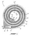
- Figure 1 is a side cross-sectional view of a heat exchanger according to an embodiment of the present invention;
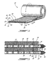
- Figure 2 is a perspective schematic view of a flexible heat exchanging assembly being rolled to form the heat exchanger of Figure 1 ;
- Figure 3 is a cross-sectional view of the heat exchanger of Figure 1 taken along line 3-3;
- Figure 4 is a top view of a manifold used in the heat exchanger of Figure 1;
- Figure 5 is a side view of the manifold of Figure 4; and
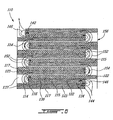
- Figure 6 is a side cross-sectional view of a heat exchanger according to another embodiment of the present invention.
- Referring to Figures 1 to 3, a
heat exchanger 10 having a spiral configuration is shown. Theheat exchanger 10 is formed by rolling a flat, flexibleheat exchanging assembly 12 to a desired circumference. Theheat exchanging assembly 12 preferably includes three superposed layers of sheet material: a first sheet offoil material 14, a second sheet offoil material 16, and a sheet ofporous material 22. - The sheets of
foil material parallel spacers 18 extending therebetween along a length thereof. Twoflexible strips 20 extend parallel to thespacers 18 to connect and seal theelongated edges 21 of the sheets offoil material 14 with theelongated edges 27 of the sheet offoil material 16. Theflexible strips 20 are offset from theelongated edges foil material strips 20. This assembly defines a plurality ofparallel fluid conduits 34 defined between the inner surfaces of the sheets offoil material adjacent spacers 18 and between eachflexible strip 20 andadjacent spacer 18. Thefluid conduits 34 will take the form of spiralling conduits once theheat exchanging assembly 12 is rolled. Preferably,such fluid conduits 34 are adaped to receiving fuel flow therethough, however other fluids such a suitable liquid for example may also be directed therethrough. - The sheets of
foil material spacers 18 are composed of a flexible material resistant to high temperatures, preferably in the form of wire or ribbons, and preferably also of a nickel alloy. Theflexible strips 20 are also preferably composed of a nickel alloy. The sheets offoil material spacers 18 andflexible strips 20 are compatible so that upon heating of the assembly they will adhere to one another, for example by pre-treating thespacers 18 andflexible strips 20 with an adequate high temperature alloy powder to permit the assembly to be sintered together. - The sheet of
porous material 22 rests against the second, inner sheet offoil material 16 such that it is in heat exchange relationship therewith. Oneribbon 24 seals each of the twoelongated edges 25 of the sheet ofporous material 22, with eachribbon 24 being preferably superimposed on a correspondingflexible strip 20 such as to form therewith an end plate of theheat exchanger 10. The sheet ofporous material 22 includes a plurality of interconnected voids or pores and as such defines awide air conduit 36 bordered by the tworibbons 24. Theair conduit 36 will be a spiralling conduit once theheat exchanging assembly 12 is rolled. In the spiral form, the sheet ofporous material 22 also rests against the first sheet offoil material 14 to be in heat exchange relationship therewith. - The sheet of
porous material 22 is composed of a heat conducting material with coarse pores, resistant to high temperatures, that is flexible in its "green" state but which solidifies upon sintering or other similar treatment. A preferable material is a nickel based foam coated with a high temperature alloy powder, most preferably a 5% dense nickel foam powdered with an alloy which will react to form a nickel alloy foam upon sintering.US Patent 6,926,969 issued Aug. 9, 2005 to Bohm et al. and International Patent Application PublicationsWO2005/037467 andWO2004/089564 , both to INCO Limited and respectively published on April 28, 2005 and October 21, 2004, disclose relevant materials and processes. Theribbons 24 are also preferably composed of a nickel alloy pre-treated with a high temperature alloy powder. The sheet ofporous material 22 is compatible with the sheets offoil material ribbons 24 so that upon heating and solidifying the sheet ofporous material 22 will adhere through sintering to theribbons 24 and the first and/or second sheet offoil material ribbons 24 andflexible strips 20, once adhered to the sheets offoil material heat exchanger 10. - Braze paste 28 further seals the outer junctions between the sheets of
foil material flexible strip 20, to provide an additional protection against leaks. Anend cap 30 containing fine poremetallic foam 32 encloses each of the elongated ends of the sheets offoil material porous material 22, such as to catch any potential leaking fluid and direct it to where it can be detected. Themetallic foam 32 serves to prevent a flame from forming if the leakage flow is a hot flammable fluid (such as fuel for example), such as by preventing flame propagation between adjacent pores of the foam material due to the limited pore size available, in the same manner that metallic screens and foams are well known to prevent flame propagation by, inter alia, rapid conduction of energy away from the flame front. Such a flame retarding feature only becomes useful when the liquid used within the heat exchanger is a flammable one, such as fuel when theheat exchanger 10 is being employed as a fuel heater for example. - The
heat exchanger 10 also includes acore 26 which seals the portion of the sheet ofporous material 22 located at the center of theheat exchanger 10. Thecore 26 includes anair outlet 40 connected at the end of thespiralling air conduit 36 and aliquid inlet 42 connected at the end of thespiralling fluid conduits 34. Theliquid inlet 42 preferably acts as a fuel inlet when the liquid fed through thefluid conduits 34 is fuel. Along the outer circumference of theheat exchanger 10 is located anair inlet 38 connected to the other end of thespiralling air conduit 36 and aliquid outlet 44 connected to the other end of thespiralling fluid conduits 34. The air and liquid inlets andoutlets manifold 46, an example of which is shown in further detail in Figures 4-5. Themanifold 46 includes aplanar duct 48, connected either to theair conduit 36 or to the plurality offluid conduits 34 at one end, and to anend tube 50 at another end. A number of other manifold geometries are possible and would be applicable to theheat exchanger 10. - As shown in Figure 1, the
heat exchanger 10 is preferably a counter flow heat exchanger to maximise efficiency, with a spirallingairflow 52 directed opposite of a spirallingliquid flow 54. Of course, theheat exchanger 10 could also be used with parallel flows or different flow orientations. - The
heat exchanger 10 is assembled according to the following. The first sheet offoil material 14 is laid flat on a support surface. Theparallel spacers 18 and the twoflexible strips 20 are placed on top of the first sheet offoil material 14, in a parallel regularly spaced apart manner, with the twoflexible strips 20 located near theelongated edges 21 of the sheet. The second sheet offoil material 16 is placed over thespacers 18 and strips 20, with itselongated edges 27 in alignment with theelongated edges 21 of the first sheet offoil material 14. The sheet ofporous material 22, bordered by theribbons 24, is disposed over the second sheet offoil material 16. The flexibleheat exchanging assembly 12 is thus formed as an unfastened "sandwiched" structure having two opposite exposed surfaces, namely one impermeable surface of the first sheet offoil material 14, and one permeable surface of the sheet ofporous material 22. Because the metallic foam composing the sheet ofporous material 22 is in its green state, thus flexible, theheat exchange assembly 12 can easily conform to a desired shape. Also, since the elements forming theheat exchanging assembly 12 are not fastened together, rolling or other shaping of theassembly 12 is facilitated, since the shaping of fastened elements can produce unwanted stress in the fastening means. - Preferable dimensions for the sheets of
foil material porous material 22 are about 10 feet (3 m) long by one foot wide (0.3 m) by 0.2 inches (5.1 mm) thick. Preferable dimensions for thespacers 18 are about 10 feet (3 m) long by 0.02 inches (0.51 mm) thick, placed 0.1 inches (2.5 mm) apart, center to center, such as to formfluid conduits 34 of 0.09 inches by 0.02 inches by 10 feet (2.3 mm by 0.51 mm by 3 m) long. Of course, these dimensions are stated as an example only and it is understood that a variety of other appropriate dimensions can be used. - The flexible
heat exchanging assembly 12, assembled as above in a flat "sandwiched" manner, is then rolled along its length to form a spiral shape, preferably around thecore 26. Upon rolling the two exposed surfaces of theheat exchanging assembly 12 come into contact with each other, i.e. the sheet ofporous material 22 abuts the first sheet offoil material 14. Thespacers 18 maintain adequate spacing between the first and second sheets offoil material - The rolled
heat exchanger 10 is then heated to a temperature (e.g. 2100-2300 degrees F (1149-1260°C)) adequate for converting the base foam material into a rigid foam and for sintering of certain elements together, as follows. The sheet ofporous material 22, sandwiched between the first and second sheets offoil material opposed foil sheets ribbons 24 are sintered to theelongated edges 25 of the sheet ofporous material 22, thus sealing them. Similarly, thestrips 20 are sintered between the first and second sheets offoil material spacers 18 are also sintered between the first and second sheets offoil material fluid conduits 34. - The remaining unsealed portions between the layers are the two ends of the
heat exchanging assembly 12, one extending axially in the center of theheat exchanger 10 and another extending axially at the outer circumference thereof. At the end located in the center, onemanifold 46 is connected to thefluid conduits 34 to form theinlet 42 and onemanifold 46 is connected to theair conduit 36 to form theair outlet 40. Such a connection can be, for example, through brazing of themanifolds 46 to the first and second sheets offoil material porous material 22. Similarly, at the end located at the outer circumference, one manifold is connected to thefluid conduits 34 to form theoutlet 44 and onemanifold 46 is connected to theair conduit 36 to form theair inlet 38. Thebraze paste 28 is added at the outer junctions between the sheets offoil material flexible strip 20, and theheat exchanger 10 is reheated in a braze furnace. The end caps 30 are connected to the elongated ends of the first and second sheets offoil material - The
heat exchanger 10 thus formed is lightweight and robust. Thespacers 18 sintered to the sheets offoil material porous material 22 can resist to high pressure, rapid air flow (e.g. 40 atmospheres (4.1 MPa), 20,000 lbs/hr (2.52 kg/s)). The preferred materials (nickel based) allow theconduits heat exchanger 10 absorbs at least most vibrations to which it is exposed and has high strength, while occupying a minimal volume because of its spiral configuration. As such, it can advantageously be used in a gas turbine engine, for example to take advantage of the thermal heat sink available in fuel to cool turbine cooling air. - Referring to Figure 6, another embodiment of the
heat exchanger 110 is shown. Theheat exchanger 110 has an accordion shape obtained through folding of a flexible heat exchanging assembly 112. The flexible heat exchanging assembly 112 includes, in order: a first sheet offoil material 115, a first sheet ofporous material 122, a second sheet offoil material 116, spacers (not shown), a third sheet offoil material 114, a second sheet ofporous material 123, and a fourth sheet offoil material 117. The material used are the same as in the previous embodiment. - A plurality of parallel
fluid conduits 134 are defined between the inner surfaces of the second and third sheets of foil material 116,114 in the free space between adjacent spacers. The first sheet ofporous material 122 is in heat exchange relationship with the second sheet offoil material 116, and the second sheet ofporous material 123 is in heat exchange relationship the third sheet offoil material 114. The sheets of porous material 122,123 thus define twoelongated air conduits fluid conduits 134 extending therebetween. - The first and second sheets of porous material 122,123 are cut into distinct portions at the folds of the
heat exchanger 110 in order to facilitate compact folding of the flexible heat exchanging assembly 112. The first and fourth sheets of foil material 115,117 are preferably discontinuous, covering every second one of the portions of their respective sheet of porous material 122,123 so that only one thickness of foil material 115,117 will be located between two adjacent folded portions of the corresponding sheet of foam material 122,123. - To assemble the
heat exchanger 10, the still flexible heat exchange assembly 112, with sheets of porous material 122,123 in their green state, is folded in an accordion manner into asheet metal container 156. Thesheet metal container 156 seals the four sides of theheat exchanger 110 and as such no ribbons or strips are required along the length of the heat exchange assembly 112 as in the previous embodiment. Theheat exchanger 110 is then heated so that the different components are sintered and the foam material becomes rigid. -
Manifolds 146 are provided at each extremity and connected to thefluid conduits 134 to form aninlet 142 and anoutlet 144. In this example, a liquid, such as fuel, flows through thefluid conduits 134 from top to bottom of theheat exchanger 110, as shown by thearrows 154. Air flows through theair conduits 137 composed of the sheets of foam material 122,123 and the free spaces in between from the top to the bottom of theheat exchanger 110, as shown by thearrows 152. Of course, theheat exchanger 110 could also be used with parallel flows or different flow orientations. - The above description is meant to be exemplary only, and one skilled in the art will recognize that changes may be made to the embodiments described without department from the scope of the invention disclosed. For example, the
heat exchange assembly 12 could be folded in an accordion pattern, or the heat exchange assembly 112 could be rolled into a spiral shape. A plurality of heat exchange assemblies 12,112, preferably interconnected, could be use to form a plurality of concentric annular shapes to form an annular heat exchanger. Thefluid conduits 34 could extend along an axial direction of the spiral, and theairflow 152 could also be fed therethrough axially, although it is understood that such a configuration would likely be less efficient. Still other modifications which fall within the scope of the present invention will be apparent to those skilled in the art, in light of a review of this disclosure, and such modifications are intended to fall within the appended claims.
Claims (19)
- A method of forming a heat exchanger (10; 110) comprising the steps of:forming a flexible heat exchanging assembly (12; 112) by:laying a first flexible sheet (14; 114) composed of heat conducting impermeable material on a support surface;laying a second flexible sheet (16; 116) composed of heat conducting impermeable material in a spaced apart manner over the first flexible sheet (14; 114) to define at least one elongated conduit (34; 134) for a first fluid flow between the first and second flexible sheets (14, 16; 114, 116); andlaying a third flexible sheet (22; 122, 123) composed of flexible heat conducting foam on the second flexible sheet (16; 116), the heat conducting foam having a plurality of interconnected pores defining a passage (36; 136, 137) therethrough for a second fluid flow;shaping the flexible heat exchanging assembly (12; 112) into a desired shape; andbonding the flexible heat exchanging assembly (12; 112) together to form a rigid heat exchanger, the at least one conduit (34; 134) and the passage (36; 136, 137) extending in a superposed manner throughout the heat exchanger in heat exchange (10; 110) relationship with one another.
- The method according to claim 1, wherein the step of shaping includes rolling of the flexible heat exchanging assembly (12) into a spiral form, and the heat exchanger (10) being a spiralling heat exchanger with the at least one conduit (34) and the passage (36) extending spirally.
- The method according to claim 1 or 2, further comprising laying a plurality of spacers (18) on the first flexible sheet (14; 114) before the step of laying the second flexible sheet (16; 116), and the second flexible sheet (16; 116) is laid on the plurality of spacers (18).
- The method according to any of claims 1 to 3, wherein the step of bonding transforms the flexible heat conducting foam into a rigid heat conducting foam.
- The method according to any preceding claim, wherein the step of bonding comprises heating of the flexible heat exchanging assembly (12).
- The method according to claim 5, wherein the heating of the flexible heat exchanging assembly (12) comprises sintering of the third flexible sheet (22) with the first and second flexible sheets (14, 16).
- The method according to claim 3, wherein a step of pre-treating the plurality of spacers (18) with a high temperature alloy powder is performed before the step of bonding, and the step of bonding further comprises heating the flexible heat exchanging assembly (12) to sinter the third flexible sheet (22) with the first and second flexible sheets (14, 16) and the plurality of spacers (18) with the first and second flexible sheets (14, 16).
- A spiral heat exchanger (10) comprising:at least one first spiralling conduit (34) for directing a first fluid flow, the at least one first spiralling conduit (34) extending between two pairs of opposed, spiralling sealed surfaces to define first and second open ends (42, 44), the first open end (44) being located near an outer circumference of the spiral heat exchanger (10), the second open end (42) being located near a core of the spiral heat exchanger (10);a second spiralling conduit (36) for directing a second fluid flow, the second conduit being adjacent the at least one first spiralling conduit (34) and in heat exchange relationship therewith, the second spiralling conduit (36) extending between two pairs of opposed, spiralling sealed surfaces to define third and fourth open ends (38, 40), the third open end (38) being located near the outer circumference, the fourth open end (40) being located near the core, the second spiralling conduit (36) including therein a heat conducting porous material (22) permitting the second fluid flow to circulate therethrough.
- The heat exchanger (10) as defined in claim 8, wherein the at least one first spiralling conduit (34) comprises a plurality of first spiralling conduits, the plurality of first spiralling conduits being separated by a plurality of spiralling spacers (18).
- The heat exchanger (10) as defined in claim 8 or 9, wherein the first open end (44) includes a first outlet, the second open end (42) includes a first inlet, the third open end (38) includes a second inlet, and the fourth open end (40) includes a second outlet, the first fluid flow being directed from the first inlet to the first outlet, and the second fluid flows being directed from the second inlet to the second outlet.
- The heat exchanger (10) as defined in any of claims 8 to 10, wherein the flexible heat conducting porous material (22) is nickel-based.
- The heat exchanger (10) as defined in any of claims 8 to 11, wherein the two pairs of opposed, spiralling sealed surfaces of the at least one first spiralling conduit (34) are composed of a nickel alloy.
- A method for manufacturing a heat exchanger (10; 110), the method comprising:forming at least one flexible heat exchanging assembly (12; 112) composed of flexible heat conducting material (14, 16, 22; 114, 115, 116, 117, 122, 133) and having at least first and second adjacent conduits (34, 36; 134, 136, 137) defined therein in heat exchange relationship with one another;shaping the at least one flexible heat exchanging assembly (12; 112) to a desired heat exchanger shape; andheating the at least one heat exchanging assembly (12; 112) to transform at least a portion of the flexible heat conducting material into a rigid heat conducting material and to rigidly bond the at least one flexible heat exchange assembly (12; 112) into the desired heat exchanger shape.
- The method as defined in claim 13, wherein a single flexible heat exchange assembly is formed, the single flexible heat exchange assembly being shaped so that at least one portion thereof is in contact with at least another portion thereof.
- The method as defined in claim 14, wherein the single flexible heat exchange assembly (12) is shaped into a spiral, the at least one portion thereof being in heat exchange relationship with the at least another portion thereof.
- The method as defined in claim 15, wherein the at least first and second superposed conduits (34; 36) extend around a circumference of the spiral.
- The method as defined in claim 14, wherein the single flexible heat exchange assembly (112) is shaped into a folded accordion shape.
- A flexible heat exchanging assembly (12; 112) of a heat exchanger (10; 110), the flexible heat exchanging assembly (12; 112) comprising:first means (14, 16; 114, 115, 116, 117, 122, 123) for conveying a first fluid flow, the first means being flexible and conducting heat;second means (22; 122, 123) for conveying a second fluid flow, the second means being flexible and conducting heat, the first and second means being in heat exchange relationship such that heat is exchangeable between the first and second fluid flows, the second means including a porous flexible material transformable into a porous rigid material through heating such that the second means become rigid.
- The flexible heat exchanging (12; 112) assembly according to claim 18, wherein the porous rigid material is a metallic foam.
Applications Claiming Priority (1)
| Application Number | Priority Date | Filing Date | Title |
|---|---|---|---|
| US11/239,110 US7467467B2 (en) | 2005-09-30 | 2005-09-30 | Method for manufacturing a foam core heat exchanger |
Publications (2)
| Publication Number | Publication Date |
|---|---|
| EP1770344A2 true EP1770344A2 (en) | 2007-04-04 |
| EP1770344A3 EP1770344A3 (en) | 2010-04-14 |
Family
ID=37532981
Family Applications (1)
| Application Number | Title | Priority Date | Filing Date |
|---|---|---|---|
| EP06255076A Withdrawn EP1770344A3 (en) | 2005-09-30 | 2006-09-29 | Foam core heat exchanger and method |
Country Status (5)
| Country | Link |
|---|---|
| US (1) | US7467467B2 (en) |
| EP (1) | EP1770344A3 (en) |
| JP (1) | JP2009510380A (en) |
| CA (1) | CA2621963C (en) |
| WO (1) | WO2007036042A1 (en) |
Cited By (1)
| Publication number | Priority date | Publication date | Assignee | Title |
|---|---|---|---|---|
| DE102008013134A1 (en) * | 2008-03-07 | 2009-09-10 | Audi Ag | A heat exchange device and method of manufacturing a heat exchange element for a heat exchange device |
Families Citing this family (17)
| Publication number | Priority date | Publication date | Assignee | Title |
|---|---|---|---|---|
| US8127829B2 (en) * | 2006-09-06 | 2012-03-06 | United Technologies Corporation | Metal foam heat exchanger |
| DE102008041556A1 (en) * | 2008-08-26 | 2010-03-04 | BSH Bosch und Siemens Hausgeräte GmbH | Refrigeration unit with heat exchanger |
| TWI420011B (en) * | 2010-01-25 | 2013-12-21 | Univ Nat Yunlin Sci & Tech | Ground cover elements |
| US10103089B2 (en) * | 2010-03-26 | 2018-10-16 | Hamilton Sundstrand Corporation | Heat transfer device with fins defining air flow channels |
| US8746975B2 (en) * | 2011-02-17 | 2014-06-10 | Media Lario S.R.L. | Thermal management systems, assemblies and methods for grazing incidence collectors for EUV lithography |
| US9279626B2 (en) * | 2012-01-23 | 2016-03-08 | Honeywell International Inc. | Plate-fin heat exchanger with a porous blocker bar |
| US20140041833A1 (en) * | 2012-08-11 | 2014-02-13 | Architectural Applications P.C. | Flexible heat and moisture transfer system |
| US11143467B2 (en) | 2015-05-20 | 2021-10-12 | Other Lab, Llc | Membrane heat exchanger system and method |
| DE102017000645A1 (en) | 2017-01-25 | 2018-07-26 | Technische Universität Darmstadt | Heat exchanger with porous Wärmeleitabschnitt |
| WO2019075121A1 (en) | 2017-10-10 | 2019-04-18 | Other Lab, Llc | Conformable heat exchanger system and method |
| WO2020160028A1 (en) | 2019-01-29 | 2020-08-06 | Treau, Inc. | Film heat exchanger coupling system and method |
| US20200368804A1 (en) * | 2019-05-24 | 2020-11-26 | Trusval Technology Co., Ltd. | Manufacturing process for heat sink composite having heat dissipation function and manufacturing method for its finished product |
| DE102019132013A1 (en) * | 2019-11-26 | 2021-05-27 | Bayerische Motoren Werke Aktiengesellschaft | Heat exchanger device for a motor vehicle, method for operating a heat exchanger device and method for producing a heat exchanger device |
| CN114158232A (en) * | 2020-09-08 | 2022-03-08 | 英业达科技有限公司 | Heat sink and heat dissipation system |
| EP3978807A3 (en) | 2020-09-30 | 2022-07-06 | Rolls-Royce plc | Direct fuel injection system |
| CA3200800A1 (en) | 2020-12-02 | 2022-06-09 | Feng Gao | Spiral heat exchanger and heat exchange device |
| PL446144A1 (en) * | 2023-09-18 | 2025-03-24 | Zieta Prozessdesign Spółka Z Ograniczoną Odpowiedzialnością | Preform of a longitudinal chamber profile and method of producing a longitudinal chamber profile |
Citations (2)
| Publication number | Priority date | Publication date | Assignee | Title |
|---|---|---|---|---|
| WO2002063231A1 (en) | 2001-02-05 | 2002-08-15 | Pursuit Dynamics Plc | Spiral flow heat exchanger |
| EP1500450A1 (en) | 2003-07-24 | 2005-01-26 | Efoam S.A. | Method for joining a metal foam to a metal part |
Family Cites Families (37)
| Publication number | Priority date | Publication date | Assignee | Title |
|---|---|---|---|---|
| US2448315A (en) | 1945-02-14 | 1948-08-31 | Gen Motors Corp | Combination restrictor and heat exchanger |
| US3444925A (en) * | 1957-05-07 | 1969-05-20 | Minnesota Mining & Mfg | Structural articles and method of making |
| GB931096A (en) * | 1958-07-02 | 1963-07-10 | Minnesota Mining & Mfg | Improvements in ceramic articles |
| US3289756A (en) | 1964-10-15 | 1966-12-06 | Olin Mathieson | Heat exchanger |
| US3401798A (en) * | 1965-01-04 | 1968-09-17 | Dorr Oliver Inc | Cylindrically stacked and spirally configured semi-permeable membrane laminate apparatus |
| US3323587A (en) * | 1965-08-19 | 1967-06-06 | Acme Ind Inc | Rolled plate type cooler |
| US3322189A (en) * | 1965-12-21 | 1967-05-30 | Ford Motor Co | Heat exchange assembly |
| US3703763A (en) * | 1970-11-18 | 1972-11-28 | Ethyl Corp | Method of making a composite metal article |
| FR2313650A1 (en) | 1975-06-05 | 1976-12-31 | Bertin & Cie | COMPACT HEAT EXCHANGER FOR FLUIDS |
| US4222434A (en) * | 1978-04-27 | 1980-09-16 | Clyde Robert A | Ceramic sponge heat-exchanger member |
| JPS555152A (en) | 1978-06-28 | 1980-01-16 | Hitachi Ltd | Production of heat exchanger |
| US4245469A (en) | 1979-04-23 | 1981-01-20 | The United States Of America As Represented By The Administrator Of The National Aeronautics And Space Administration | Heat exchanger and method of making |
| GB2132330A (en) | 1982-12-20 | 1984-07-04 | Apv Co Ltd | Spiral heat exchanger |
| JPS62795A (en) | 1985-06-26 | 1987-01-06 | Agency Of Ind Science & Technol | Heat accumulating device utilizing spiral type heat exchanger |
| JPS63187095A (en) * | 1987-01-29 | 1988-08-02 | Matsushita Electric Ind Co Ltd | Heat exchanger |
| US4898234A (en) | 1988-08-19 | 1990-02-06 | Mcdonnell Douglas Corporation | Air heat exchanger |
| US5145001A (en) | 1989-07-24 | 1992-09-08 | Creare Inc. | High heat flux compact heat exchanger having a permeable heat transfer element |
| US5029638A (en) | 1989-07-24 | 1991-07-09 | Creare Incorporated | High heat flux compact heat exchanger having a permeable heat transfer element |
| EP0492031A1 (en) | 1990-12-21 | 1992-07-01 | Innovazioni Tecnologiche Di Flavio Dal Bo | A heat recuperation device for sanitary installations |
| US5231968A (en) | 1992-07-27 | 1993-08-03 | Donald Siefkes | Foamed metal heat device |
| US5267611A (en) | 1993-01-08 | 1993-12-07 | Thermacore, Inc. | Single phase porous layer heat exchanger |
| US5326537A (en) | 1993-01-29 | 1994-07-05 | Cleary James M | Counterflow catalytic device |
| JPH074874A (en) | 1993-06-11 | 1995-01-10 | Kurose:Kk | Method and apparatus for operating spiral heat exchanger |
| EP0744586B1 (en) * | 1993-12-27 | 2004-03-17 | Hitachi Chemical Co., Ltd. | Method of manufacturing a heat transmitting device and a heat transmitting device |
| ES2292242T5 (en) | 1998-05-15 | 2011-05-04 | Genentech, Inc. | THERAPEUTIC USES OF IL-17 HOMOLOGICAL POLYPEPTIDES. |
| KR19990085965A (en) | 1998-05-23 | 1999-12-15 | 박호군 | Porous Fin Plate Heat Exchanger |
| US6196307B1 (en) | 1998-06-17 | 2001-03-06 | Intersil Americas Inc. | High performance heat exchanger and method |
| KR20010076991A (en) | 2000-01-29 | 2001-08-17 | 박호군 | Foam metal heat sink |
| US6840307B2 (en) | 2000-03-14 | 2005-01-11 | Delphi Technologies, Inc. | High performance heat exchange assembly |
| US6424529B2 (en) | 2000-03-14 | 2002-07-23 | Delphi Technologies, Inc. | High performance heat exchange assembly |
| NL1016713C2 (en) | 2000-11-27 | 2002-05-29 | Stork Screens Bv | Heat exchanger and such a heat exchanger comprising thermo-acoustic conversion device. |
| WO2002096538A1 (en) * | 2001-05-29 | 2002-12-05 | Pall Corporation | Tubular membrane and method of making |
| DE10150948C1 (en) | 2001-10-11 | 2003-05-28 | Fraunhofer Ges Forschung | Process for the production of sintered porous bodies |
| KR20040088554A (en) * | 2002-02-26 | 2004-10-16 | 미크로스 매뉴팩처링 인코포레이티드 | Capillary evaporator |
| DE10316929B3 (en) | 2003-04-07 | 2004-09-16 | Fraunhofer-Gesellschaft zur Förderung der angewandten Forschung e.V. | Production of open-pore molded body, used as particle filter, involves coating open pore body made from nickel or iron with metal powder, to form mixed crystals or intermetallic phases using organic binder, and further processing |
| DE10346281B4 (en) | 2003-09-30 | 2006-06-22 | Fraunhofer-Gesellschaft zur Förderung der angewandten Forschung e.V. | Method for producing components with a nickel-based alloy and components produced therewith |
| DE102005037763B4 (en) * | 2005-08-10 | 2008-07-24 | Fraunhofer-Gesellschaft zur Förderung der angewandten Forschung e.V. | Cylindrical heat exchanger in thermal contact with an adsorbent |
-
2005
- 2005-09-30 US US11/239,110 patent/US7467467B2/en not_active Expired - Fee Related
-
2006
- 2006-09-28 JP JP2008532548A patent/JP2009510380A/en active Pending
- 2006-09-28 WO PCT/CA2006/001601 patent/WO2007036042A1/en not_active Ceased
- 2006-09-28 CA CA2621963A patent/CA2621963C/en not_active Expired - Fee Related
- 2006-09-29 EP EP06255076A patent/EP1770344A3/en not_active Withdrawn
Patent Citations (2)
| Publication number | Priority date | Publication date | Assignee | Title |
|---|---|---|---|---|
| WO2002063231A1 (en) | 2001-02-05 | 2002-08-15 | Pursuit Dynamics Plc | Spiral flow heat exchanger |
| EP1500450A1 (en) | 2003-07-24 | 2005-01-26 | Efoam S.A. | Method for joining a metal foam to a metal part |
Cited By (1)
| Publication number | Priority date | Publication date | Assignee | Title |
|---|---|---|---|---|
| DE102008013134A1 (en) * | 2008-03-07 | 2009-09-10 | Audi Ag | A heat exchange device and method of manufacturing a heat exchange element for a heat exchange device |
Also Published As
| Publication number | Publication date |
|---|---|
| WO2007036042A1 (en) | 2007-04-05 |
| US20070234565A1 (en) | 2007-10-11 |
| CA2621963C (en) | 2013-01-08 |
| CA2621963A1 (en) | 2007-04-05 |
| US7467467B2 (en) | 2008-12-23 |
| JP2009510380A (en) | 2009-03-12 |
| EP1770344A3 (en) | 2010-04-14 |
Similar Documents
| Publication | Publication Date | Title |
|---|---|---|
| CA2621963C (en) | Foam core heat exchanger and method | |
| US6474408B1 (en) | Heat exchanger with bypass seal allowing differential thermal expansion | |
| US8371365B2 (en) | Heat exchange device and method for manufacture | |
| CN102695936B (en) | Stacked/bar plate charge air cooler including inlet and outlet tanks | |
| JP5797740B2 (en) | Heat exchange member and heat exchanger | |
| EP0753712B1 (en) | A heat exchanger | |
| US9097473B2 (en) | Ceramic heat exchanger and method of producing same | |
| US10527369B2 (en) | Heat exchanger element, manufacturing method therefor, and heat exchanger | |
| JPWO2019135312A1 (en) | Heat exchanger, heat exchanger and heat exchanger with purification means | |
| TWI764487B (en) | Block style heat exchanger for heat pipe reactor | |
| CN107167000B (en) | Plate heat exchanger and method for manufacturing a plate heat exchanger | |
| CN102369410A (en) | Plate heat exchanger and method for improving pressure resistance of plate heat exchanger | |
| CN104246178A (en) | Micro gas turbine plant with annular recuperator | |
| US7150099B2 (en) | Heat exchanger for high-temperature applications | |
| JP7299902B2 (en) | heat exchanger with stack of cells | |
| EP3091323B1 (en) | Heat exchanger member and heat exchanger | |
| US20150144309A1 (en) | Flattened Envelope Heat Exchanger | |
| WO2018081119A1 (en) | Heat exchanger with porous material | |
| US20220381521A1 (en) | Additively manufactured porous heat exchanger | |
| US20130062039A1 (en) | System and method for exchanging heat | |
| CN220187498U (en) | All-welded plate type heat exchange device | |
| WO2015081274A1 (en) | Flattened envelope heat exchanger | |
| KR101202773B1 (en) | Micro channel heat exchanger | |
| JPH04324030A (en) | gas turbine combustor | |
| JPH07280488A (en) | Heat exchanger |
Legal Events
| Date | Code | Title | Description |
|---|---|---|---|
| PUAI | Public reference made under article 153(3) epc to a published international application that has entered the european phase |
Free format text: ORIGINAL CODE: 0009012 |
|
| AK | Designated contracting states |
Kind code of ref document: A2 Designated state(s): AT BE BG CH CY CZ DE DK EE ES FI FR GB GR HU IE IS IT LI LT LU LV MC NL PL PT RO SE SI SK TR |
|
| AX | Request for extension of the european patent |
Extension state: AL BA HR MK YU |
|
| PUAL | Search report despatched |
Free format text: ORIGINAL CODE: 0009013 |
|
| AK | Designated contracting states |
Kind code of ref document: A3 Designated state(s): AT BE BG CH CY CZ DE DK EE ES FI FR GB GR HU IE IS IT LI LT LU LV MC NL PL PT RO SE SI SK TR |
|
| AX | Request for extension of the european patent |
Extension state: AL BA HR MK RS |
|
| 17P | Request for examination filed |
Effective date: 20100616 |
|
| 17Q | First examination report despatched |
Effective date: 20100722 |
|
| AKX | Designation fees paid |
Designated state(s): DE FR GB |
|
| STAA | Information on the status of an ep patent application or granted ep patent |
Free format text: STATUS: THE APPLICATION IS DEEMED TO BE WITHDRAWN |
|
| 18D | Application deemed to be withdrawn |
Effective date: 20130403 |