EP1770280A1 - Compressor with induction electric element - Google Patents
Compressor with induction electric element Download PDFInfo
- Publication number
- EP1770280A1 EP1770280A1 EP06018185A EP06018185A EP1770280A1 EP 1770280 A1 EP1770280 A1 EP 1770280A1 EP 06018185 A EP06018185 A EP 06018185A EP 06018185 A EP06018185 A EP 06018185A EP 1770280 A1 EP1770280 A1 EP 1770280A1
- Authority
- EP
- European Patent Office
- Prior art keywords
- rotor
- stator
- lower portion
- upper portion
- stator core
- Prior art date
- Legal status (The legal status is an assumption and is not a legal conclusion. Google has not performed a legal analysis and makes no representation as to the accuracy of the status listed.)
- Granted
Links
- 230000006698 induction Effects 0.000 title claims abstract description 40
- 230000000717 retained effect Effects 0.000 claims abstract description 9
- 239000003507 refrigerant Substances 0.000 claims description 18
- 238000004519 manufacturing process Methods 0.000 description 10
- 229910000831 Steel Inorganic materials 0.000 description 7
- 238000005520 cutting process Methods 0.000 description 7
- 238000010438 heat treatment Methods 0.000 description 7
- 238000000034 method Methods 0.000 description 7
- 239000010959 steel Substances 0.000 description 7
- 230000000694 effects Effects 0.000 description 5
- 230000015572 biosynthetic process Effects 0.000 description 4
- 238000004080 punching Methods 0.000 description 4
- 238000003860 storage Methods 0.000 description 2
- 230000006835 compression Effects 0.000 description 1
- 238000007906 compression Methods 0.000 description 1
- XLYOFNOQVPJJNP-UHFFFAOYSA-N water Substances O XLYOFNOQVPJJNP-UHFFFAOYSA-N 0.000 description 1
- 238000004804 winding Methods 0.000 description 1
Images


Classifications
-
- F—MECHANICAL ENGINEERING; LIGHTING; HEATING; WEAPONS; BLASTING
- F04—POSITIVE - DISPLACEMENT MACHINES FOR LIQUIDS; PUMPS FOR LIQUIDS OR ELASTIC FLUIDS
- F04B—POSITIVE-DISPLACEMENT MACHINES FOR LIQUIDS; PUMPS
- F04B35/00—Piston pumps specially adapted for elastic fluids and characterised by the driving means to their working members, or by combination with, or adaptation to, specific driving engines or motors, not otherwise provided for
- F04B35/04—Piston pumps specially adapted for elastic fluids and characterised by the driving means to their working members, or by combination with, or adaptation to, specific driving engines or motors, not otherwise provided for the means being electric
-
- F—MECHANICAL ENGINEERING; LIGHTING; HEATING; WEAPONS; BLASTING
- F04—POSITIVE - DISPLACEMENT MACHINES FOR LIQUIDS; PUMPS FOR LIQUIDS OR ELASTIC FLUIDS
- F04C—ROTARY-PISTON, OR OSCILLATING-PISTON, POSITIVE-DISPLACEMENT MACHINES FOR LIQUIDS; ROTARY-PISTON, OR OSCILLATING-PISTON, POSITIVE-DISPLACEMENT PUMPS
- F04C23/00—Combinations of two or more pumps, each being of rotary-piston or oscillating-piston type, specially adapted for elastic fluids; Pumping installations specially adapted for elastic fluids; Multi-stage pumps specially adapted for elastic fluids
- F04C23/008—Hermetic pumps
-
- F—MECHANICAL ENGINEERING; LIGHTING; HEATING; WEAPONS; BLASTING
- F04—POSITIVE - DISPLACEMENT MACHINES FOR LIQUIDS; PUMPS FOR LIQUIDS OR ELASTIC FLUIDS
- F04C—ROTARY-PISTON, OR OSCILLATING-PISTON, POSITIVE-DISPLACEMENT MACHINES FOR LIQUIDS; ROTARY-PISTON, OR OSCILLATING-PISTON, POSITIVE-DISPLACEMENT PUMPS
- F04C29/00—Component parts, details or accessories of pumps or pumping installations, not provided for in groups F04C18/00 - F04C28/00
- F04C29/0042—Driving elements, brakes, couplings, transmissions specially adapted for pumps
- F04C29/0085—Prime movers
-
- H—ELECTRICITY
- H02—GENERATION; CONVERSION OR DISTRIBUTION OF ELECTRIC POWER
- H02K—DYNAMO-ELECTRIC MACHINES
- H02K1/00—Details of the magnetic circuit
- H02K1/06—Details of the magnetic circuit characterised by the shape, form or construction
- H02K1/12—Stationary parts of the magnetic circuit
- H02K1/16—Stator cores with slots for windings
-
- H—ELECTRICITY
- H02—GENERATION; CONVERSION OR DISTRIBUTION OF ELECTRIC POWER
- H02K—DYNAMO-ELECTRIC MACHINES
- H02K1/00—Details of the magnetic circuit
- H02K1/06—Details of the magnetic circuit characterised by the shape, form or construction
- H02K1/22—Rotating parts of the magnetic circuit
- H02K1/26—Rotor cores with slots for windings
-
- F—MECHANICAL ENGINEERING; LIGHTING; HEATING; WEAPONS; BLASTING
- F04—POSITIVE - DISPLACEMENT MACHINES FOR LIQUIDS; PUMPS FOR LIQUIDS OR ELASTIC FLUIDS
- F04C—ROTARY-PISTON, OR OSCILLATING-PISTON, POSITIVE-DISPLACEMENT MACHINES FOR LIQUIDS; ROTARY-PISTON, OR OSCILLATING-PISTON, POSITIVE-DISPLACEMENT PUMPS
- F04C28/00—Control of, monitoring of, or safety arrangements for, pumps or pumping installations specially adapted for elastic fluids
- F04C28/06—Control of, monitoring of, or safety arrangements for, pumps or pumping installations specially adapted for elastic fluids specially adapted for stopping, starting, idling or no-load operation
-
- H—ELECTRICITY
- H02—GENERATION; CONVERSION OR DISTRIBUTION OF ELECTRIC POWER
- H02K—DYNAMO-ELECTRIC MACHINES
- H02K15/00—Processes or apparatus specially adapted for manufacturing, assembling, maintaining or repairing of dynamo-electric machines
- H02K15/16—Centring rotors within the stators
-
- H—ELECTRICITY
- H02—GENERATION; CONVERSION OR DISTRIBUTION OF ELECTRIC POWER
- H02K—DYNAMO-ELECTRIC MACHINES
- H02K7/00—Arrangements for handling mechanical energy structurally associated with dynamo-electric machines, e.g. structural association with mechanical driving motors or auxiliary dynamo-electric machines
- H02K7/08—Structural association with bearings
- H02K7/085—Structural association with bearings radially supporting the rotary shaft at only one end of the rotor
-
- H—ELECTRICITY
- H02—GENERATION; CONVERSION OR DISTRIBUTION OF ELECTRIC POWER
- H02K—DYNAMO-ELECTRIC MACHINES
- H02K7/00—Arrangements for handling mechanical energy structurally associated with dynamo-electric machines, e.g. structural association with mechanical driving motors or auxiliary dynamo-electric machines
- H02K7/14—Structural association with mechanical loads, e.g. with hand-held machine tools or fans
Definitions
- the present invention relates to an induction electric element housed compressor, and more particularly to a reliable induction electric element housed compressor capable of preventing a stator core from touching a rotor core at the time of starting or the like.
- a conventional hermetic compressor is shown in section in Fig. 3.
- the reference numeral 50 denotes a hermetic container having an oil storage 51 that stores oil in the bottom.
- the container houses an induction electric element 52 in an upper portion and a rotation compressive element 53 in a lower portion.
- the induction electric element 52 includes a rotor core 55 installed on a rotation axis 54, and a stator core 57 having an oil return hole 56 formed in the outer circumference.
- the reference numeral 58 denotes an air gap formed between the outer circumference of the rotor core 55 and the inner circumference of the stator core 57.
- the reference numeral 59 denotes a coil end of a winding contained in the stator core 57.
- the rotation compressive element 53 includes a cylinder 60, a roller 62 that is forced to rotate within the cylinder 60 by an eccentric portion 61 of the rotation axis 54, and a vane 63 that adjoins the roller to divide the inside of the cylinder 60.
- the rotation compressive element also includes an upper bearing portion 64 and a lower bearing portion 65 provided to close the openings of the cylinder, a discharge valve 66 attached to the upper bearing portion, and a cup muffler 67 that covers the discharge valve.
- the reference numeral 68 denotes a discharge hole provided in the cup muffler 67.
- the reference numeral 69 denotes a refrigerant discharge pipe provided through the center of the upper portion of the hermetic container 50, which is tightly closed by bonding an end cap 70 thereto.
- the reference numeral 71 denotes an accumulator. The arrow indicates the flow of the refrigerant.
- the refrigerant compressed at the rotation compressive element 53 is sent out through the air gap 58 of the induction electric element 52 to the upper portion of the electric element.
- the oil contained therein is separated by a centrifugal force caused from rotations of the rotor core 55.
- the separated oil is scattered toward the stator core 57.
- the refrigerant is discharged through the refrigerant discharge pipe 69 to external from the hermetic container 50.
- the separated oil returns from the oil return hole 56 formed in the outer circumference of the stator core 57 to the oil storage 51 in the hermetic container 50.
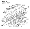
- Fig. 4 is an illustrative view illustrating a punch for manufacturing the rotor core 55 and the stator core 57 of prior art (see Patent Document 1: JP Patent No. 3,557,046 ).
- the reference numeral 79 denotes a punch for manufacturing the rotor core 55 and the stator core 57.
- the punch 79 includes a plurality of punching male molds [80(1)-84(1) in the first line and 80(2)-84(2) in the second line] for manufacturing rotor core members and a plurality of punching male molds [86(1)-88(1) in the first line and 86(2)-88(2) in the second line] for manufacturing stator core members in the upper portion; and a plurality of punching female molds in the lower portion corresponding to the above respective male molds.
- a steel belt S is supplied continuously in between the male molds and the female molds while the male molds are moved up and down to punch out the steel belt S at required locations in two lines zigzag along the width and sequentially along the length to manufacture the rotor core members having a plurality of crimps.
- the reference numerals 85(1) and 85(2) denote female molds for producing the rotor core by pressurizing and automatically stacking a required number of the rotor core members, and 89 (1) and 89(2) denote outlets for extracting the rotor core 55 therefrom.
- the steel belt S from which the rotor core members have been punched out is further subjected to punching out the outer circumferential portions at required locations in turn to produce the stator core members having a plurality of crimps.
- a required number of the stator core members are automatically stacked to produce the stator core 57.
- the reference numerals 91 (1) and 91(2) denote female molds for producing the stator core 57 by pressurizing and automatically stacking a required number of the stator core members, and 90(1) and 90(2) denote outlets for extracting the stator core 57 therefrom.
- the reference symbol A denotes a play not to be punched out.
- Fig. 5(a) is an illustrative view showing an example of the rotor core member manufactured through the above method
- (b) is an illustrative view showing the rotor core 55 produced by pressurizing and stacking a required number of the rotor core members.
- the reference symbol K in the figure denotes a crimp.
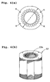
- Fig. 6(a) is an illustrative view showing an example of the stator core member manufactured through the above method
- (b) is an illustrative view showing the stator core 57 produced by pressurizing and stacking a required number of the stator core members.
- the reference symbol K in the figure denotes a crimp.
- the outer circumference of the upper end 55A of the rotor core 55 attached to the rotation shaft 54 may contact the inner circumference of the upper end 57A of the stator core 57. This may result in damage to the upper end 55 and the upper end 57A, which leads to a suction failure, a reduction in performance, and a halt of running as a critical problem.
- the present invention has an object to solve the conventional problems and provide a reliable induction electric element housed compressor capable of preventing a stator core from contacting a rotor core, thereby achieving stable running over a long period even at the time of starting or frequently repeating starting-running.
- the present invention provides an induction electric element housed compressor, comprising: a hermetic container; a compressive element housed in a lower portion of the container; and an induction electric element housed in an upper portion of the container, the induction electric element including a stator core fixedly attached on an inner wall of the hermetic container to drive the compressive element, and a rotor core attached to a rotation axis and inserted in the stator core, the compressive element operative to compress a refrigerant led therein and discharge the compressed refrigerant to external from the hermetic container.
- the stator core has a stator lower portion formed by automatically stacking a required number of stator core members (A) having a certain inner diameter such that an appropriate air gap is retained between the stator lower portion and the rotor core, a stator upper portion formed adjacent to the stator lower portion by automatically stacking a required number of stator core members (B) having a larger inner diameter than the inner diameter of the stator lower portion, and a stepped portion formed on a position where the stator lower portion adjoins the stator upper portion.
- the present invention provides an induction electric element housed compressor, comprising: a hermetic container; a compressive element housed in a lower portion of the container; and an induction electric element housed in an upper portion of the container, the induction electric element including a stator core fixedly attached on an inner wall of the hermetic container to drive the
- the rotor core has a rotor lower portion formed by automatically stacking a required number of rotor core members (C) having a certain outer diameter such that an appropriate air gap is retained between the rotor lower portion and the stator core, a rotor upper portion formed adjacent to the rotor lower portion by automatically stacking a required number of rotor core members (D) having a smaller outer diameter than the outer diameter of the rotor lower portion, and a stepped portion formed on a position where the rotor lower portion adjoins the rotor upper portion.
- C rotor core members
- D required number of rotor core members
- L3 denoting a length of the rotor upper portion and L4 denoting a total length of [(the length of the rotor upper portion) + (the length of the rotor lower portion)] have a relation represented by the following expression (3)
- R2 denoting the outer diameter of the rotor lower portion and R1 denoting the outer diameter of the rotor upper portion have a relation represented by the following expression (4):
- L ⁇ 3 / L ⁇ 4 ⁇ 100 0.01 - 50 %
- R ⁇ 1 / R ⁇ 2 ⁇ 100 80 - 99.99 %
- the induction electric element housed compressor comprises a hermetic container; a compressive element housed in a lower portion of the container; and an induction electric element housed in an upper portion of the container, the induction electric element including a stator core fixedly attached on an inner wall of the hermetic container to drive the compressive element, and a rotor core attached to a rotation axis and inserted in the stator core, the compressive element operative to compress a refrigerant led therein and discharge the compressed refrigerant to external from the hermetic container.
- the stator core has a stator lower portion formed by automatically stacking a required number of stator core members (A) having a certain inner diameter such that an appropriate air gap is retained between the stator lower portion and the rotor core, a stator upper portion formed adjacent to the stator lower portion by automatically stacking a required number of stator core members (B) having a larger inner diameter than the inner diameter of the stator lower portion, and a stepped portion formed on a position where the stator lower portion adjoins the stator upper portion.
- the compressor instead of cutting and heating the outer circumference of the upper end of the rotor core as performed conventionally, uses the stator core formed by automatically stacking respective required numbers of stator core members (A) and (B) to form a stepped portion on a position where the stator lower portion adjoins the stator upper portion. Accordingly, it is possible to form a low-cost, high-precision induction electric element with a suppressed increase in process steps.
- the use of this induction electric element prevents the outer circumference of the upper end of the rotor core from contacting the inner circumference of the upper end of the stator core even at the time of starting or frequently repeating starting-running. Therefore, it is possible to provide a reliable induction electric element housed compressor capable of achieving stable running over a long period as a remarkable effect.
- L1 denoting a length of the stator upper portion and L2 denoting a total length of [(the length of the stator upper portion) + (the length of the stator lower portion)] have a relation represented by the above expression (1)
- D1 denoting the inner diameter of the stator lower portion and D2 denoting the inner diameter of the stator upper portion have a relation represented by the above expression (2).
- the induction electric element housed compressor comprises a hermetic container; a compressive element housed in a lower portion of the container; and an induction electric element housed in an upper portion of the container, the induction electric element including a stator core fixedly attached on an inner wall of the hermetic container to drive the compressive element, and a rotor core attached to a rotation axis and inserted in the stator core, the compressive element operative to compress a refrigerant led therein and discharge the compressed refrigerant to external from the hermetic container.
- the rotor core has a rotor lower portion formed by automatically stacking a required number of rotor core members (C) having a certain outer diameter such that an appropriate air gap is retained between the rotor lower portion and the stator core, a rotor upper portion formed adjacent to the rotor lower portion by automatically stacking a required number of rotor core members (D) having a smaller outer diameter than the outer diameter of the rotor lower portion, and a stepped portion formed on a position where the rotor lower portion adjoins the rotor upper portion.
- C rotor core members
- D required number of rotor core members
- the compressor instead of cutting and heating the outer circumference of the upper end of the rotor core as performed conventionally, uses the rotor core formed by automatically stacking respective required numbers of rotor core members (C) and (D) to form a stepped portion on a position where the rotor lower portion adjoins the rotor upper portion. Accordingly, it is possible to form a low-cost, high-precision induction electric element with a suppressed increase in process steps. The use of this induction electric element prevents the outer circumference of the upper end of the rotor core from contacting the inner circumference of the upper end of the stator core even at the time of starting or frequently repeating starting-running. Therefore, it is possible to provide a reliable induction electric element housed compressor capable of achieving stable running over a long period as a remarkable effect.
- L3 denoting a length of the rotor upper portion and L4 denoting a total length of [(the length of the rotor upper portion) + (the length of the rotor lower portion)] have a relation represented by the above expression (3)
- R2 denoting the outer diameter of the rotor lower portion and R1 denoting the outer diameter of the rotor upper portion have a relation represented by the above expression (4).
- the stator core 57 is formed by pressurizing and automatically stacking a required number of stator core members A having a certain inner diameter (D1) such that an air gap formed between the inner circumference of the stator lower portion 57-2 and the outer circumference of a rotor core 55 (not shown) is retained at an appropriate value.
- a stator upper portion 57-1 adjacent to the stator lower portion 57-2 is formed by pressurizing and automatically stacking a required number of stator core members B having a larger inner diameter (D2) than the inner diameter (D1).
- a stepped portion 57-3 is formed on a position where the stator lower portion 57-2 adjoins the stator upper portion 57-1 in the stator core 57. Others are similar to those of the stator core 57 shown in Fig. 6.
- the stator lower portion 57-2 and the stator upper portion 57-1 have the same outer diameter of r.
- stator core members A, B and the stator core 57 In order to manufacture the stator core members A, B and the stator core 57, the punch shown in Fig. 4 is reconstructed. A steel belt S is then supplied continuously in between the male molds and the female molds while the male molds are moved up and down to punch out the steel belt S at required locations in two lines zigzag along the width and sequentially along the length to automatically manufacture the stator core members A, B having a plurality of crimps. A required number of the manufactured stator core members A are automatically and sequentially pressurized and stacked to form the stator lower portion 57-2. In addition, a required number of the stator core members B are automatically and sequentially pressurized and stacked thereon to form the stator upper portion 57-1, thus producing the stator core 57.
- L1 denoting a length of the stator upper portion 57-1 and L2 denoting a total length of [(the length L1 of the stator upper portion 57-1) + (the length of the stator lower portion)] have a relation represented by the following expression (1)
- D1 denoting the inner diameter of the stator lower portion 57-2 and D2 denoting the inner diameter of the stator upper portion 57-1 have a relation represented by the following expression (2):
- L ⁇ 1 / L ⁇ 2 ⁇ 100 0.01 - 50 %
- D ⁇ 1 / D ⁇ 2 ⁇ 100 80 - 99.99 %
- [(L1)/(L2)] ⁇ 100 has a value below 0.01 (%)
- the outer circumference of the upper end 55A of the rotor core 55 may not be prevented from contacting the inner circumference of the upper end 57A of the stator core 57 possibly at the time of starting or frequently repeating starting- running. If it exceeds 50 (%), the running property is
- the compressor according to the first embodiment of the present invention is similar to the compressor shown in Fig. 3 except for the use of the above stator core 57 and the rotor core 55 shown in Fig. 5 as the rotor core.
- the compressor of the present invention uses the stator core 57 formed by automatically stacking respective required numbers of stator core members A, B to form the stepped portion 57-3 on a position where the stator lower portion 57-2 adjoins the stator upper portion 57-1. Accordingly, it is possible to prevent the outer circumference of the upper end 55A of the rotor core 55 (not shown) from contacting the inner circumference of the upper end 57A of the stator core even at the time of starting or frequently repeating starting-running. Accordingly, stable running can be achieved over a long period with high reliability.
- the rotor lower portion 55-2 of the rotor core 55 is formed by pressurizing and automatically stacking a required number of rotor core members C having a certain outer diameter (R2) such that an air gap between the outer circumference of the rotor lower portion 55-2 and the inner circumference of the stator core (not shown) is retained at an appropriate value.
- a rotor upper portion 55-1 of the rotor core 55 adjacent to the rotor lower portion 55-2 is formed by automatically stacking a required number of rotor core members D having a smaller outer diameter (R1) than the outer diameter (R2).
- a stepped portion 55-3 is formed on a position where the rotor lower portion 55-2 adjoins the rotor upper portion 55-1 in the rotor core 55. Others are similar to those of the rotor core 55 shown in Fig. 5.
- the rotor lower portion 55-2 and the rotor upper portion 55-1 are designed to have the same inner diameter.
- the punch shown in Fig. 4 is reconstructed.
- a steel belt S is then supplied continuously in between the male molds and the female molds while the male molds are moved up and down to punch out the steel belt S at required locations in two lines zigzag along the width and sequentially along the length to manufacture the rotor core members C, D having a plurality of crimps.
- a required number of the manufactured rotor core members C are automatically and sequentially pressurized and stacked to form the rotor lower portion 55-2.
- a required number of the rotor core members D are automatically and sequentially pressurized and stacked thereon to form the rotor upper portion 55-1, thus producing the rotor core 55.
- L3 denoting a length of the rotor upper portion 55-1 and L4 denoting a total length of [(the length L3 of the rotor upper portion 55-1) + (the length of the rotor lower portion 55-2)] have a relation represented by the following expression (3)
- R2 denoting the outer diameter of the rotor lower portion 55-2 and R1 denoting the outer diameter of the rotor upper portion 55-1 have a relation represented by the following expression (4):
- L ⁇ 3 / L ⁇ 4 ⁇ 100 0.01 - 50 %
- R ⁇ 1 / R ⁇ 2 ⁇ 100 80 - 99.99 %
- [(L3)/(L4)] ⁇ 100 has a value below 0.01 (%)
- the outer circumference of the upper end 55A of the rotor core 55 may not be prevented from contacting the inner circumference of the upper end 57A of the stator core 57 (not shown) possibly at the time of starting or frequently repeating starting-running. If it exceeds 50 (%)
- the compressor according to the second embodiment of the present invention is similar to the compressor shown in Fig. 3 except for the use of the above rotor core 55 and the stator core 57 shown in Fig. 6 as the stator core.
- the compressor of the present invention uses the rotor core 55 formed by automatically stacking respective required numbers of rotor core members C, D to form the stepped portion 55-3 on a position where the rotor lower portion 55-2 adjoins the rotor upper portion 55-1. Accordingly, it is possible to prevent the outer circumference of the upper end 55A of the rotor core 55 from contacting the inner circumference of the upper end 57A of the stator core 57 even at the time of starting or frequently repeating starting-running. Accordingly, stable running can be achieved over a long period with high reliability.
- stator core 57 formed of the stator upper portion 57-1 with a larger inner diameter and the stator lower portion 57-2 with a smaller inner diameter and the example of the rotor core formed of the rotor upper portion 55-1 with a smaller outer diameter and the rotor lower portion 55-2 with a larger outer diameter are separately described though they may be used solely or in combination.
- L1 denoting a length of the stator upper portion 57-1 and L2 denoting a total length of [(the length L1 of the stator upper portion 57-1) + (the length of the stator lower portion)] have a relation represented by the following expression (1);
- D1 denoting the inner diameter of the stator lower portion 57-2 and D2 denoting the inner diameter of the stator upper portion 57-1 have a relation represented by the following expression (2);
- L3 denoting a length of the rotor upper portion 55-1 and L4 denoting a total length of [(the length L3 of the rotor upper portion 55-1) + (the length of the rotor lower portion 55-2)] have a relation represented by the following expression (3);
- R2 denoting the outer diameter of the rotor lower portion 55-2 and R1 denoting the outer diameter of the rotor upper portion 55-1 have a relation represented by the following expression (4).
- the outer circumference of the upper end 55A of the rotor core 55 can be surely prevented from contacting the inner circumference of the upper end 57A of the stator core 57.
- L ⁇ 3 / L ⁇ 4 ⁇ 100 0.01 - 50 %
- R ⁇ 1 / R ⁇ 2 ⁇ 100 80 - 99.99 %
- the rotary compressor is described though the compressor type in the present invention is not particularly limited. Specifically, the present invention is also applicable to a reciprocating compressor, a vibrating compressor, a multi-vane rotary compressor, and a scrolling compressor.
- the number of compressions may include at least one stage.
- the compressor of the present invention is available in home air conditioners, business air conditioners (packaged air conditioners), vehicular air conditioners, home refrigerators, business refrigerators, business freezers, business freezers/ refrigerators, showcases, vending machines, and hot water suppliers.
- the compressor of the present invention uses the stator core or the rotor core formed by automatically stacking respective required numbers of stator core members A, B or rotor core members C, D to form the stepped portion on a position where the lower portion adjoins the upper portion. Accordingly, it is possible to form a low-cost, high-precision induction electric element with a suppressed increase in process steps. In addition, it is possible to prevent the outer circumference of the upper end of the rotor core from contacting the inner circumference of the upper end of the stator core even at the time of starting or frequently repeating starting-running. Accordingly, stable running can be achieved over a long period with high reliability as a remarkable effect, which provides a high industrial usefulness.
Landscapes
- Engineering & Computer Science (AREA)
- Mechanical Engineering (AREA)
- General Engineering & Computer Science (AREA)
- Power Engineering (AREA)
- Iron Core Of Rotating Electric Machines (AREA)
- Compressor (AREA)
- Manufacture Of Motors, Generators (AREA)
- Applications Or Details Of Rotary Compressors (AREA)
Abstract
Description
- The present invention relates to an induction electric element housed compressor, and more particularly to a reliable induction electric element housed compressor capable of preventing a stator core from touching a rotor core at the time of starting or the like.
- A conventional hermetic compressor is shown in section in Fig. 3.
- The
reference numeral 50 denotes a hermetic container having anoil storage 51 that stores oil in the bottom. The container houses an inductionelectric element 52 in an upper portion and a rotationcompressive element 53 in a lower portion. The inductionelectric element 52 includes arotor core 55 installed on arotation axis 54, and astator core 57 having anoil return hole 56 formed in the outer circumference. Thereference numeral 58 denotes an air gap formed between the outer circumference of therotor core 55 and the inner circumference of thestator core 57. Thereference numeral 59 denotes a coil end of a winding contained in thestator core 57. The rotationcompressive element 53 includes acylinder 60, a roller 62 that is forced to rotate within thecylinder 60 by aneccentric portion 61 of therotation axis 54, and avane 63 that adjoins the roller to divide the inside of thecylinder 60. The rotation compressive element also includes an upper bearingportion 64 and alower bearing portion 65 provided to close the openings of the cylinder, adischarge valve 66 attached to the upper bearing portion, and acup muffler 67 that covers the discharge valve. Thereference numeral 68 denotes a discharge hole provided in thecup muffler 67. Thereference numeral 69 denotes a refrigerant discharge pipe provided through the center of the upper portion of thehermetic container 50, which is tightly closed by bonding anend cap 70 thereto. Thereference numeral 71 denotes an accumulator. The arrow indicates the flow of the refrigerant. - In the hermetic compressor thus structured, the refrigerant compressed at the rotation
compressive element 53 is sent out through theair gap 58 of the inductionelectric element 52 to the upper portion of the electric element. From the refrigerant sent out to the upper portion of the inductionelectric element 52, the oil contained therein is separated by a centrifugal force caused from rotations of therotor core 55. The separated oil is scattered toward thestator core 57. The refrigerant is discharged through therefrigerant discharge pipe 69 to external from thehermetic container 50. The separated oil returns from theoil return hole 56 formed in the outer circumference of thestator core 57 to theoil storage 51 in thehermetic container 50. - Fig. 4 is an illustrative view illustrating a punch for manufacturing the
rotor core 55 and thestator core 57 of prior art (see Patent Document 1:JP Patent No. 3,557,046 - In Fig. 4 the
reference numeral 79 denotes a punch for manufacturing therotor core 55 and thestator core 57. Thepunch 79 includes a plurality of punching male molds [80(1)-84(1) in the first line and 80(2)-84(2) in the second line] for manufacturing rotor core members and a plurality of punching male molds [86(1)-88(1) in the first line and 86(2)-88(2) in the second line] for manufacturing stator core members in the upper portion; and a plurality of punching female molds in the lower portion corresponding to the above respective male molds. - A steel belt S is supplied continuously in between the male molds and the female molds while the male molds are moved up and down to punch out the steel belt S at required locations in two lines zigzag along the width and sequentially along the length to manufacture the rotor core members having a plurality of crimps.
- The reference numerals 85(1) and 85(2) denote female molds for producing the rotor core by pressurizing and automatically stacking a required number of the rotor core members, and 89 (1) and 89(2) denote outlets for extracting the
rotor core 55 therefrom. - The steel belt S from which the rotor core members have been punched out is further subjected to punching out the outer circumferential portions at required locations in turn to produce the stator core members having a plurality of crimps. A required number of the stator core members are automatically stacked to produce the
stator core 57. The reference numerals 91 (1) and 91(2) denote female molds for producing thestator core 57 by pressurizing and automatically stacking a required number of the stator core members, and 90(1) and 90(2) denote outlets for extracting thestator core 57 therefrom. The reference symbol A denotes a play not to be punched out. - Fig. 5(a) is an illustrative view showing an example of the rotor core member manufactured through the above method, and (b) is an illustrative view showing the
rotor core 55 produced by pressurizing and stacking a required number of the rotor core members. The reference symbol K in the figure denotes a crimp. - Fig. 6(a) is an illustrative view showing an example of the stator core member manufactured through the above method, and (b) is an illustrative view showing the
stator core 57 produced by pressurizing and stacking a required number of the stator core members. The reference symbol K in the figure denotes a crimp. - In the conventional hermetic compressor, at the time of starting or frequently repeating starting-running, the outer circumference of the
upper end 55A of therotor core 55 attached to therotation shaft 54 may contact the inner circumference of theupper end 57A of thestator core 57. This may result in damage to theupper end 55 and theupper end 57A, which leads to a suction failure, a reduction in performance, and a halt of running as a critical problem. - Therefore, the location where the outer circumference of the
upper end 55A of therotor core 55 contacts the inner circumference of theupper end 57A of thestator core 57 has been subjected to cutting and heating. This is effective to reduce the outer diameter of theupper end 55A and prevent both from contacting with each other. The processes of cutting and heating increase the process steps correspondingly and even a skilled person requires time and effort for a precise finish, which results in an increase in cost as a problem. - The present invention has an object to solve the conventional problems and provide a reliable induction electric element housed compressor capable of preventing a stator core from contacting a rotor core, thereby achieving stable running over a long period even at the time of starting or frequently repeating starting-running.
- To solve the above problems, in a first aspect the present invention provides an induction electric element housed compressor, comprising: a hermetic container; a compressive element housed in a lower portion of the container; and an induction electric element housed in an upper portion of the container, the induction electric element including a stator core fixedly attached on an inner wall of the hermetic container to drive the compressive element, and a rotor core attached to a rotation axis and inserted in the stator core, the compressive element operative to compress a refrigerant led therein and discharge the compressed refrigerant to external from the hermetic container.
- The stator core has a stator lower portion formed by automatically stacking a required number of stator core members (A) having a certain inner diameter such that an appropriate air gap is retained between the stator lower portion and the rotor core, a stator upper portion formed adjacent to the stator lower portion by automatically stacking a required number of stator core members (B) having a larger inner diameter than the inner diameter of the stator lower portion, and a stepped portion formed on a position where the stator lower portion adjoins the stator upper portion.
- In the induction electric element housed compressor according to a second aspect of the present invention, L1 denoting a length of the stator upper portion and L2 denoting a total length of [(the length of the stator upper portion) + (the length of the stator lower portion)] have a relation represented by the following expression (1), and D1 denoting the inner diameter of the stator lower portion and D2 denoting the inner diameter of the stator upper portion have a relation represented by the following expression (2):


- The rotor core has a rotor lower portion formed by automatically stacking a required number of rotor core members (C) having a certain outer diameter such that an appropriate air gap is retained between the rotor lower portion and the stator core, a rotor upper portion formed adjacent to the rotor lower portion by automatically stacking a required number of rotor core members (D) having a smaller outer diameter than the outer diameter of the rotor lower portion, and a stepped portion formed on a position where the rotor lower portion adjoins the rotor upper portion.
- In the induction electric element housed compressor according to a fourth aspect of the present invention, L3 denoting a length of the rotor upper portion and L4 denoting a total length of [(the length of the rotor upper portion) + (the length of the rotor lower portion)] have a relation represented by the following expression (3), and R2 denoting the outer diameter of the rotor lower portion and R1 denoting the outer diameter of the rotor upper portion have a relation represented by the following expression (4):


- The induction electric element housed compressor according to the first aspect of the present invention comprises a hermetic container; a compressive element housed in a lower portion of the container; and an induction electric element housed in an upper portion of the container, the induction electric element including a stator core fixedly attached on an inner wall of the hermetic container to drive the compressive element, and a rotor core attached to a rotation axis and inserted in the stator core, the compressive element operative to compress a refrigerant led therein and discharge the compressed refrigerant to external from the hermetic container.
- The stator core has a stator lower portion formed by automatically stacking a required number of stator core members (A) having a certain inner diameter such that an appropriate air gap is retained between the stator lower portion and the rotor core, a stator upper portion formed adjacent to the stator lower portion by automatically stacking a required number of stator core members (B) having a larger inner diameter than the inner diameter of the stator lower portion, and a stepped portion formed on a position where the stator lower portion adjoins the stator upper portion.
- In this case, instead of cutting and heating the outer circumference of the upper end of the rotor core as performed conventionally, the compressor uses the stator core formed by automatically stacking respective required numbers of stator core members (A) and (B) to form a stepped portion on a position where the stator lower portion adjoins the stator upper portion. Accordingly, it is possible to form a low-cost, high-precision induction electric element with a suppressed increase in process steps. The use of this induction electric element prevents the outer circumference of the upper end of the rotor core from contacting the inner circumference of the upper end of the stator core even at the time of starting or frequently repeating starting-running. Therefore, it is possible to provide a reliable induction electric element housed compressor capable of achieving stable running over a long period as a remarkable effect.
- In the induction electric element housed compressor according to the second aspect of the present invention, L1 denoting a length of the stator upper portion and L2 denoting a total length of [(the length of the stator upper portion) + (the length of the stator lower portion)] have a relation represented by the above expression (1), and D1 denoting the inner diameter of the stator lower portion and D2 denoting the inner diameter of the stator upper portion have a relation represented by the above expression (2). Thus, the outer circumference of the upper end of the rotor core can be further reliably prevented from contacting the inner circumference of the upper end of the stator core even at the time of starting or frequently repeating starting-running. Therefore, it is possible to provide a reliable induction electric element housed compressor capable of achieving stable running over a long period as a further remarkable effect.
- The induction electric element housed compressor according to the third aspect of the present invention comprises a hermetic container; a compressive element housed in a lower portion of the container; and an induction electric element housed in an upper portion of the container, the induction electric element including a stator core fixedly attached on an inner wall of the hermetic container to drive the compressive element, and a rotor core attached to a rotation axis and inserted in the stator core, the compressive element operative to compress a refrigerant led therein and discharge the compressed refrigerant to external from the hermetic container.
- The rotor core has a rotor lower portion formed by automatically stacking a required number of rotor core members (C) having a certain outer diameter such that an appropriate air gap is retained between the rotor lower portion and the stator core, a rotor upper portion formed adjacent to the rotor lower portion by automatically stacking a required number of rotor core members (D) having a smaller outer diameter than the outer diameter of the rotor lower portion, and a stepped portion formed on a position where the rotor lower portion adjoins the rotor upper portion.
- In this case, instead of cutting and heating the outer circumference of the upper end of the rotor core as performed conventionally, the compressor uses the rotor core formed by automatically stacking respective required numbers of rotor core members (C) and (D) to form a stepped portion on a position where the rotor lower portion adjoins the rotor upper portion. Accordingly, it is possible to form a low-cost, high-precision induction electric element with a suppressed increase in process steps. The use of this induction electric element prevents the outer circumference of the upper end of the rotor core from contacting the inner circumference of the upper end of the stator core even at the time of starting or frequently repeating starting-running. Therefore, it is possible to provide a reliable induction electric element housed compressor capable of achieving stable running over a long period as a remarkable effect.
- In the induction electric element housed compressor according to the fourth aspect of the present invention, L3 denoting a length of the rotor upper portion and L4 denoting a total length of [(the length of the rotor upper portion) + (the length of the rotor lower portion)] have a relation represented by the above expression (3), and R2 denoting the outer diameter of the rotor lower portion and R1 denoting the outer diameter of the rotor upper portion have a relation represented by the above expression (4). Thus, the outer circumference of the upper end of the rotor core can be further reliably prevented from contacting the inner circumference of the upper end of the stator core even at the time of starting or frequently repeating starting-running. Therefore, it is possible to provide a reliable induction electric element housed compressor capable of achieving stable running over a long period as a further remarkable effect.
-
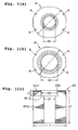
- Fig. 1 (a), (b) and (c) are illustrative views illustrating an embodiment associated with a stator core in a compressor of the present invention;
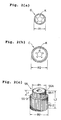
- Fig. 2(a), (b) and (c) are illustrative views illustrating an embodiment associated with a rotor core in the compressor of the present invention;
- Fig. 3 is an illustrative view illustrating a hermetic compressor in section;
- Fig. 4 is an illustrative view illustrating a punch for manufacturing the stator core and the rotor core;
- Fig. 5 provides (a) an illustrative view showing an example of a rotor core member and (b) an illustrative view showing a rotor core formed by pressurizing and stacking a required number of such rotor core members of prior art; and
- Fig. 6 provides (a) an illustrative view showing an example of a stator core member and (b) an illustrative view showing a stator core formed by pressurizing and stacking a required number of such stator core members of prior art.
- The embodiments of the present invention will now be described in detail with reference to the drawings.
-
- Fig. 1 (a), (b) and (c) are illustrative views illustrating an embodiment associated with a stator core in a compressor of the present invention.
- Fig. 1(a) is an illustrative view illustrating a stator core member A for use in formation of a rotor lower portion 57-2 of a
stator core 57 in the compressor of the present invention. - Fig. 1(b) is an illustrative view illustrating a stator core member B for use in formation of a rotor upper portion 57-1 of the
stator core 57 in the compressor of the present invention. - Fig. 1(c) is an illustrative view illustrating the
stator core 57 in the compressor of the present invention. - The
stator core 57 is formed by pressurizing and automatically stacking a required number of stator core members A having a certain inner diameter (D1) such that an air gap formed between the inner circumference of the stator lower portion 57-2 and the outer circumference of a rotor core 55 (not shown) is retained at an appropriate value. A stator upper portion 57-1 adjacent to the stator lower portion 57-2 is formed by pressurizing and automatically stacking a required number of stator core members B having a larger inner diameter (D2) than the inner diameter (D1). A stepped portion 57-3 is formed on a position where the stator lower portion 57-2 adjoins the stator upper portion 57-1 in thestator core 57. Others are similar to those of thestator core 57 shown in Fig. 6. The stator lower portion 57-2 and the stator upper portion 57-1 have the same outer diameter of r. - In order to manufacture the stator core members A, B and the
stator core 57, the punch shown in Fig. 4 is reconstructed. A steel belt S is then supplied continuously in between the male molds and the female molds while the male molds are moved up and down to punch out the steel belt S at required locations in two lines zigzag along the width and sequentially along the length to automatically manufacture the stator core members A, B having a plurality of crimps. A required number of the manufactured stator core members A are automatically and sequentially pressurized and stacked to form the stator lower portion 57-2. In addition, a required number of the stator core members B are automatically and sequentially pressurized and stacked thereon to form the stator upper portion 57-1, thus producing thestator core 57. - Preferably, L1 denoting a length of the stator upper portion 57-1 and L2 denoting a total length of [(the length L1 of the stator upper portion 57-1) + (the length of the stator lower portion)] have a relation represented by the following expression (1), and D1 denoting the inner diameter of the stator lower portion 57-2 and D2 denoting the inner diameter of the stator upper portion 57-1 have a relation represented by the following expression (2):


upper end 55A of the rotor core 55 (not shown) may not be prevented from contacting the inner circumference of theupper end 57A of thestator core 57 possibly at the time of starting or frequently repeating starting- running. If it exceeds 50 (%), the running property is worsened. - If [(D1)/(D2)] × 100 has a value below 80 (%), the running property is worsened. If it exceeds 99.99 (%), the outer circumference of the
upper end 55A of the rotor core 55 (not shown) may not be prevented from contacting the inner circumference of theupper end 57A of thestator core 57 possibly at the time of starting or frequently repeating starting-running. - The compressor according to the first embodiment of the present invention is similar to the compressor shown in Fig. 3 except for the use of the
above stator core 57 and therotor core 55 shown in Fig. 5 as the rotor core. - Instead of cutting and heating the outer circumference of the upper end of the rotor core as performed conventionally, the compressor of the present invention uses the
stator core 57 formed by automatically stacking respective required numbers of stator core members A, B to form the stepped portion 57-3 on a position where the stator lower portion 57-2 adjoins the stator upper portion 57-1. Accordingly, it is possible to prevent the outer circumference of theupper end 55A of the rotor core 55 (not shown) from contacting the inner circumference of theupper end 57A of the stator core even at the time of starting or frequently repeating starting-running. Accordingly, stable running can be achieved over a long period with high reliability. -
- Fig. 2 (a), (b) and (c) are illustrative views illustrating an embodiment associated with a rotor core in the compressor of the present invention.
- Fig. 2(a) is an illustrative view illustrating a rotor core member D for use in formation of a rotor upper portion 55-1 of a
rotor core 55 in the compressor of the present invention. - Fig. 2(b) is an illustrative view illustrating a rotor core member C for use in formation of a rotor lower portion 55-2 of the
rotor core 55 in the compressor of the present invention. - Fig. 2(c) is an illustrative view illustrating the
rotor core 55 in the compressor of the present invention. - The rotor lower portion 55-2 of the
rotor core 55 is formed by pressurizing and automatically stacking a required number of rotor core members C having a certain outer diameter (R2) such that an air gap between the outer circumference of the rotor lower portion 55-2 and the inner circumference of the stator core (not shown) is retained at an appropriate value. A rotor upper portion 55-1 of therotor core 55 adjacent to the rotor lower portion 55-2 is formed by automatically stacking a required number of rotor core members D having a smaller outer diameter (R1) than the outer diameter (R2). A stepped portion 55-3 is formed on a position where the rotor lower portion 55-2 adjoins the rotor upper portion 55-1 in therotor core 55. Others are similar to those of therotor core 55 shown in Fig. 5. The rotor lower portion 55-2 and the rotor upper portion 55-1 are designed to have the same inner diameter. - In order to manufacture the rotor core members C, D and the
rotor core 55, the punch shown in Fig. 4 is reconstructed. A steel belt S is then supplied continuously in between the male molds and the female molds while the male molds are moved up and down to punch out the steel belt S at required locations in two lines zigzag along the width and sequentially along the length to manufacture the rotor core members C, D having a plurality of crimps. A required number of the manufactured rotor core members C are automatically and sequentially pressurized and stacked to form the rotor lower portion 55-2. In addition, a required number of the rotor core members D are automatically and sequentially pressurized and stacked thereon to form the rotor upper portion 55-1, thus producing therotor core 55. - Preferably, L3 denoting a length of the rotor upper portion 55-1 and L4 denoting a total length of [(the length L3 of the rotor upper portion 55-1) + (the length of the rotor lower portion 55-2)] have a relation represented by the following expression (3), and R2 denoting the outer diameter of the rotor lower portion 55-2 and R1 denoting the outer diameter of the rotor upper portion 55-1 have a relation represented by the following expression (4):


upper end 55A of therotor core 55 may not be prevented from contacting the inner circumference of theupper end 57A of the stator core 57 (not shown) possibly at the time of starting or frequently repeating starting-running. If it exceeds 50 (%), the running property is worsened. - If [(R1)/(R2)] × 100 has a value below 80 (%), the running property is worsened. If it exceeds 99.99 (%), the outer circumference of the
upper end 55A of therotor core 55 may not be prevented from contacting the inner circumference of theupper end 57A of the stator core 57 (not shown) possibly at the time of starting or frequently repeating starting-running. - The compressor according to the second embodiment of the present invention is similar to the compressor shown in Fig. 3 except for the use of the
above rotor core 55 and thestator core 57 shown in Fig. 6 as the stator core. - Instead of cutting and heating the outer circumference of the upper end of the rotor core as performed conventionally, the compressor of the present invention uses the
rotor core 55 formed by automatically stacking respective required numbers of rotor core members C, D to form the stepped portion 55-3 on a position where the rotor lower portion 55-2 adjoins the rotor upper portion 55-1. Accordingly, it is possible to prevent the outer circumference of theupper end 55A of therotor core 55 from contacting the inner circumference of theupper end 57A of thestator core 57 even at the time of starting or frequently repeating starting-running. Accordingly, stable running can be achieved over a long period with high reliability. - The description of the above embodiments is applied to describe the present invention and is not intended to limit the invention as recited in the claims or reduce the scope thereof. The components of the present invention are not limited to the above embodiments but rather can be modified variously with the technical scope recited in the claims.
- In the embodiments, the example of the
stator core 57 formed of the stator upper portion 57-1 with a larger inner diameter and the stator lower portion 57-2 with a smaller inner diameter and the example of the rotor core formed of the rotor upper portion 55-1 with a smaller outer diameter and the rotor lower portion 55-2 with a larger outer diameter are separately described though they may be used solely or in combination. - If the use in combination, L1 denoting a length of the stator upper portion 57-1 and L2 denoting a total length of [(the length L1 of the stator upper portion 57-1) + (the length of the stator lower portion)] have a relation represented by the following expression (1); D1 denoting the inner diameter of the stator lower portion 57-2 and D2 denoting the inner diameter of the stator upper portion 57-1 have a relation represented by the following expression (2); L3 denoting a length of the rotor upper portion 55-1 and L4 denoting a total length of [(the length L3 of the rotor upper portion 55-1) + (the length of the rotor lower portion 55-2)] have a relation represented by the following expression (3); and R2 denoting the outer diameter of the rotor lower portion 55-2 and R1 denoting the outer diameter of the rotor upper portion 55-1 have a relation represented by the following expression (4). Even in such the relations, the outer circumference of the
upper end 55A of therotor core 55 can be surely prevented from contacting the inner circumference of theupper end 57A of thestator core 57.


- The compressor of the present invention is available in home air conditioners, business air conditioners (packaged air conditioners), vehicular air conditioners, home refrigerators, business refrigerators, business freezers, business freezers/ refrigerators, showcases, vending machines, and hot water suppliers.
- Instead of cutting and heating the outer circumference of the upper end of the rotor core as performed conventionally, the compressor of the present invention uses the stator core or the rotor core formed by automatically stacking respective required numbers of stator core members A, B or rotor core members C, D to form the stepped portion on a position where the lower portion adjoins the upper portion. Accordingly, it is possible to form a low-cost, high-precision induction electric element with a suppressed increase in process steps. In addition, it is possible to prevent the outer circumference of the upper end of the rotor core from contacting the inner circumference of the upper end of the stator core even at the time of starting or frequently repeating starting-running. Accordingly, stable running can be achieved over a long period with high reliability as a remarkable effect, which provides a high industrial usefulness.
Claims (4)
- An induction electric element housed compressor, comprising:a hermetic container;a compressive element housed in a lower portion of the container; andan induction electric element housed in an upper portion of the container, the induction electric element including a stator core fixedly attached on an inner wall of the hermetic container to drive the compressive element, and a rotor core attached to a rotation axis and inserted in the stator core, the compressive element operative to compress a refrigerant led therein and discharge the compressed refrigerant to external from the hermetic container,wherein the stator core has a stator lower portion formed by automatically stacking a required number of stator core members (A) having a certain inner diameter such that an appropriate air gap is retained between the stator lower portion and the rotor core, a stator upper portion formed adjacent to the stator lower portion by automatically stacking a required number of stator core members (B) having a larger inner diameter than the inner diameter of the stator lower portion, and a stepped portion formed on a position where the stator lower portion adjoins the stator upper portion.
- The compressor according to claim 1, wherein L1 denoting a length of the stator upper portion and L2 denoting a total length of [(the length of the stator upper portion) + (the length of the stator lower portion)] have a relation represented by the following expression (1), and wherein D1 denoting the inner diameter of the stator lower portion and D2 denoting the inner diameter of the stator upper portion have a relation represented by the following expression (2):


- An induction electric element housed compressor, comprising:a hermetic container;a compressive element housed in a lower portion of the container; andan induction electric element housed in an upper portion of the container, the induction electric element including a stator core fixedly attached on an inner wall of the hermetic container to drive the compressive element, and a rotor core attached to a rotation axis and inserted in the stator core, the compressive element operative to compress a refrigerant led therein and discharge the compressed refrigerant to external from the hermetic container,wherein the rotor core has a rotor lower portion formed by automatically stacking a required number of rotor core members (C) having a certain outer diameter such that an appropriate air gap is retained between the rotor lower portion and the stator core, a rotor upper portion formed adjacent to the rotor lower portion by automatically stacking a required number of rotor core members (D) having a smaller outer diameter than the outer diameter of the rotor lower portion, and a stepped portion formed on a position where the rotor lower portion adjoins the rotor upper portion.
- The compressor according to claim 3, wherein L3 denoting a length of the rotor upper portion and L4 denoting a total length of [(the length of the rotor upper portion) + (the length of the rotor lower portion)] have a relation represented by the following expression (3), and wherein R2 denoting the outer diameter of the rotor lower portion and R1 denoting the outer diameter of the rotor upper portion have a relation represented by the following expression (4):


Applications Claiming Priority (2)
| Application Number | Priority Date | Filing Date | Title |
|---|---|---|---|
| JP2005289025 | 2005-09-30 | ||
| JP2005330940A JP2007124877A (en) | 2005-09-30 | 2005-11-16 | Compressor accommodating induction electric element |
Publications (2)
| Publication Number | Publication Date |
|---|---|
| EP1770280A1 true EP1770280A1 (en) | 2007-04-04 |
| EP1770280B1 EP1770280B1 (en) | 2008-10-08 |
Family
ID=37235989
Family Applications (1)
| Application Number | Title | Priority Date | Filing Date |
|---|---|---|---|
| EP06018185A Not-in-force EP1770280B1 (en) | 2005-09-30 | 2006-08-31 | Compressor with induction electric element |
Country Status (6)
| Country | Link |
|---|---|
| EP (1) | EP1770280B1 (en) |
| JP (1) | JP2007124877A (en) |
| CN (1) | CN1940291B (en) |
| AT (1) | ATE410598T1 (en) |
| DE (1) | DE602006003036D1 (en) |
| DK (1) | DK1770280T3 (en) |
Families Citing this family (2)
| Publication number | Priority date | Publication date | Assignee | Title |
|---|---|---|---|---|
| CN103840584A (en) * | 2013-12-20 | 2014-06-04 | 珠海凌达压缩机有限公司 | Motor rotor of rotary compressor and processing and assembling method thereof |
| KR20220002592A (en) * | 2019-12-11 | 2022-01-06 | 안후이 메이즈 프리시전 매뉴팩처링 컴퍼니 리미티드 | Motors, compressors and air conditioners |
Citations (4)
| Publication number | Priority date | Publication date | Assignee | Title |
|---|---|---|---|---|
| US4881879A (en) * | 1987-12-24 | 1989-11-21 | Tecumseh Products Company | Rotary compressor gas routing for muffler system |
| US5233254A (en) * | 1992-03-27 | 1993-08-03 | General Electric Company | Conical rotor for switched reluctance machine |
| DE19743321A1 (en) * | 1996-09-30 | 1998-04-09 | Aisin Seiki | Switched reluctance motor e.g. for electric- or hybrid- vehicles |
| WO2001028070A2 (en) * | 1999-10-12 | 2001-04-19 | Danfoss Compressors Gmbh | Electric motor comprising a rotor mounted on one side |
Family Cites Families (3)
| Publication number | Priority date | Publication date | Assignee | Title |
|---|---|---|---|---|
| JP2001286112A (en) * | 2000-03-30 | 2001-10-12 | Sanyo Electric Co Ltd | Refrigerant compressor |
| KR20040044027A (en) * | 2002-11-20 | 2004-05-27 | 엘지전자 주식회사 | Magnet fixing structure of rotary compressor |
| CN1782435A (en) * | 2004-11-30 | 2006-06-07 | 乐金电子(天津)电器有限公司 | Rotory noise preventer of closed rotary compressor |
-
2005
- 2005-11-16 JP JP2005330940A patent/JP2007124877A/en active Pending
-
2006
- 2006-08-31 DK DK06018185T patent/DK1770280T3/en active
- 2006-08-31 AT AT06018185T patent/ATE410598T1/en not_active IP Right Cessation
- 2006-08-31 DE DE602006003036T patent/DE602006003036D1/en active Active
- 2006-08-31 EP EP06018185A patent/EP1770280B1/en not_active Not-in-force
- 2006-09-06 CN CN2006101281722A patent/CN1940291B/en not_active Expired - Fee Related
Patent Citations (4)
| Publication number | Priority date | Publication date | Assignee | Title |
|---|---|---|---|---|
| US4881879A (en) * | 1987-12-24 | 1989-11-21 | Tecumseh Products Company | Rotary compressor gas routing for muffler system |
| US5233254A (en) * | 1992-03-27 | 1993-08-03 | General Electric Company | Conical rotor for switched reluctance machine |
| DE19743321A1 (en) * | 1996-09-30 | 1998-04-09 | Aisin Seiki | Switched reluctance motor e.g. for electric- or hybrid- vehicles |
| WO2001028070A2 (en) * | 1999-10-12 | 2001-04-19 | Danfoss Compressors Gmbh | Electric motor comprising a rotor mounted on one side |
Also Published As
| Publication number | Publication date |
|---|---|
| DE602006003036D1 (en) | 2008-11-20 |
| CN1940291A (en) | 2007-04-04 |
| JP2007124877A (en) | 2007-05-17 |
| ATE410598T1 (en) | 2008-10-15 |
| EP1770280B1 (en) | 2008-10-08 |
| CN1940291B (en) | 2011-04-20 |
| DK1770280T3 (en) | 2009-01-26 |
Similar Documents
| Publication | Publication Date | Title |
|---|---|---|
| JP4026318B2 (en) | Hermetic electric compressor | |
| EP2636902B1 (en) | Scroll compressor | |
| US20130251576A1 (en) | Scroll compressor and processing method of scroll | |
| JP2006132419A (en) | Compressor | |
| KR20010021178A (en) | Multi-Cylinder Rotary Compressor | |
| CN101737325B (en) | Rotary compressor | |
| EP2385255A2 (en) | Hermetic compressor and manufacturing method thereof | |
| KR100675549B1 (en) | Electric compressor | |
| CN111033953B (en) | Stator, motor provided with the stator, compressor provided with the motor, and air conditioner provided with the compressor | |
| CN102312836B (en) | Multi-cylinder rotary compressor, assembling method thereof and manufacturing device thereof | |
| JP2002168183A (en) | Scroll compressor | |
| US9841024B2 (en) | Compressor and method for producing compressor | |
| EP1770280B1 (en) | Compressor with induction electric element | |
| RU2472035C1 (en) | Scroll compressor | |
| TW446797B (en) | Hermetic compressor and manufacture of enclosed case in hermetic compressor | |
| WO2017047338A1 (en) | Hermetic electric compressor | |
| JP2014109204A (en) | Compressor | |
| JP2012036822A (en) | Compressor | |
| JP5157148B2 (en) | Compressor | |
| CN116136217B (en) | Compressor with a compressor body having a rotor with a rotor shaft | |
| JP2020007928A (en) | Scroll compressor | |
| JP4548411B2 (en) | Compressor | |
| JP2019035391A (en) | Compressor | |
| JP6467796B2 (en) | Stator, motor and compressor | |
| JP2001207962A (en) | Vertical hermetic compressor |
Legal Events
| Date | Code | Title | Description |
|---|---|---|---|
| PUAI | Public reference made under article 153(3) epc to a published international application that has entered the european phase |
Free format text: ORIGINAL CODE: 0009012 |
|
| AK | Designated contracting states |
Kind code of ref document: A1 Designated state(s): AT BE BG CH CY CZ DE DK EE ES FI FR GB GR HU IE IS IT LI LT LU LV MC NL PL PT RO SE SI SK TR |
|
| AX | Request for extension of the european patent |
Extension state: AL BA HR MK YU |
|
| 17P | Request for examination filed |
Effective date: 20070428 |
|
| 17Q | First examination report despatched |
Effective date: 20070601 |
|
| AKX | Designation fees paid |
Designated state(s): AT BE BG CH CY CZ DE DK EE ES FI FR GB GR HU IE IS IT LI LT LU LV MC NL PL PT RO SE SI SK TR |
|
| GRAP | Despatch of communication of intention to grant a patent |
Free format text: ORIGINAL CODE: EPIDOSNIGR1 |
|
| GRAS | Grant fee paid |
Free format text: ORIGINAL CODE: EPIDOSNIGR3 |
|
| GRAA | (expected) grant |
Free format text: ORIGINAL CODE: 0009210 |
|
| AK | Designated contracting states |
Kind code of ref document: B1 Designated state(s): AT BE BG CH CY CZ DE DK EE ES FI FR GB GR HU IE IS IT LI LT LU LV MC NL PL PT RO SE SI SK TR |
|
| REG | Reference to a national code |
Ref country code: GB Ref legal event code: FG4D |
|
| REG | Reference to a national code |
Ref country code: CH Ref legal event code: EP |
|
| REG | Reference to a national code |
Ref country code: IE Ref legal event code: FG4D |
|
| REF | Corresponds to: |
Ref document number: 602006003036 Country of ref document: DE Date of ref document: 20081120 Kind code of ref document: P |
|
| REG | Reference to a national code |
Ref country code: GR Ref legal event code: EP Ref document number: 20080403338 Country of ref document: GR |
|
| REG | Reference to a national code |
Ref country code: DK Ref legal event code: T3 |
|
| PG25 | Lapsed in a contracting state [announced via postgrant information from national office to epo] |
Ref country code: SI Free format text: LAPSE BECAUSE OF FAILURE TO SUBMIT A TRANSLATION OF THE DESCRIPTION OR TO PAY THE FEE WITHIN THE PRESCRIBED TIME-LIMIT Effective date: 20081008 |
|
| NLV1 | Nl: lapsed or annulled due to failure to fulfill the requirements of art. 29p and 29m of the patents act | ||
| PG25 | Lapsed in a contracting state [announced via postgrant information from national office to epo] |
Ref country code: BG Free format text: LAPSE BECAUSE OF FAILURE TO SUBMIT A TRANSLATION OF THE DESCRIPTION OR TO PAY THE FEE WITHIN THE PRESCRIBED TIME-LIMIT Effective date: 20090108 Ref country code: AT Free format text: LAPSE BECAUSE OF FAILURE TO SUBMIT A TRANSLATION OF THE DESCRIPTION OR TO PAY THE FEE WITHIN THE PRESCRIBED TIME-LIMIT Effective date: 20081008 Ref country code: ES Free format text: LAPSE BECAUSE OF FAILURE TO SUBMIT A TRANSLATION OF THE DESCRIPTION OR TO PAY THE FEE WITHIN THE PRESCRIBED TIME-LIMIT Effective date: 20090119 Ref country code: LT Free format text: LAPSE BECAUSE OF FAILURE TO SUBMIT A TRANSLATION OF THE DESCRIPTION OR TO PAY THE FEE WITHIN THE PRESCRIBED TIME-LIMIT Effective date: 20081008 |
|
| PG25 | Lapsed in a contracting state [announced via postgrant information from national office to epo] |
Ref country code: IS Free format text: LAPSE BECAUSE OF FAILURE TO SUBMIT A TRANSLATION OF THE DESCRIPTION OR TO PAY THE FEE WITHIN THE PRESCRIBED TIME-LIMIT Effective date: 20090208 Ref country code: PL Free format text: LAPSE BECAUSE OF FAILURE TO SUBMIT A TRANSLATION OF THE DESCRIPTION OR TO PAY THE FEE WITHIN THE PRESCRIBED TIME-LIMIT Effective date: 20081008 Ref country code: NL Free format text: LAPSE BECAUSE OF FAILURE TO SUBMIT A TRANSLATION OF THE DESCRIPTION OR TO PAY THE FEE WITHIN THE PRESCRIBED TIME-LIMIT Effective date: 20081008 Ref country code: PT Free format text: LAPSE BECAUSE OF FAILURE TO SUBMIT A TRANSLATION OF THE DESCRIPTION OR TO PAY THE FEE WITHIN THE PRESCRIBED TIME-LIMIT Effective date: 20090218 Ref country code: LV Free format text: LAPSE BECAUSE OF FAILURE TO SUBMIT A TRANSLATION OF THE DESCRIPTION OR TO PAY THE FEE WITHIN THE PRESCRIBED TIME-LIMIT Effective date: 20081008 Ref country code: FI Free format text: LAPSE BECAUSE OF FAILURE TO SUBMIT A TRANSLATION OF THE DESCRIPTION OR TO PAY THE FEE WITHIN THE PRESCRIBED TIME-LIMIT Effective date: 20081008 |
|
| PG25 | Lapsed in a contracting state [announced via postgrant information from national office to epo] |
Ref country code: EE Free format text: LAPSE BECAUSE OF FAILURE TO SUBMIT A TRANSLATION OF THE DESCRIPTION OR TO PAY THE FEE WITHIN THE PRESCRIBED TIME-LIMIT Effective date: 20081008 Ref country code: RO Free format text: LAPSE BECAUSE OF FAILURE TO SUBMIT A TRANSLATION OF THE DESCRIPTION OR TO PAY THE FEE WITHIN THE PRESCRIBED TIME-LIMIT Effective date: 20081008 Ref country code: BE Free format text: LAPSE BECAUSE OF FAILURE TO SUBMIT A TRANSLATION OF THE DESCRIPTION OR TO PAY THE FEE WITHIN THE PRESCRIBED TIME-LIMIT Effective date: 20081008 |
|
| PLBE | No opposition filed within time limit |
Free format text: ORIGINAL CODE: 0009261 |
|
| STAA | Information on the status of an ep patent application or granted ep patent |
Free format text: STATUS: NO OPPOSITION FILED WITHIN TIME LIMIT |
|
| PG25 | Lapsed in a contracting state [announced via postgrant information from national office to epo] |
Ref country code: SE Free format text: LAPSE BECAUSE OF FAILURE TO SUBMIT A TRANSLATION OF THE DESCRIPTION OR TO PAY THE FEE WITHIN THE PRESCRIBED TIME-LIMIT Effective date: 20090108 Ref country code: CZ Free format text: LAPSE BECAUSE OF FAILURE TO SUBMIT A TRANSLATION OF THE DESCRIPTION OR TO PAY THE FEE WITHIN THE PRESCRIBED TIME-LIMIT Effective date: 20081008 |
|
| 26N | No opposition filed |
Effective date: 20090709 |
|
| PG25 | Lapsed in a contracting state [announced via postgrant information from national office to epo] |
Ref country code: SK Free format text: LAPSE BECAUSE OF FAILURE TO SUBMIT A TRANSLATION OF THE DESCRIPTION OR TO PAY THE FEE WITHIN THE PRESCRIBED TIME-LIMIT Effective date: 20081008 |
|
| PG25 | Lapsed in a contracting state [announced via postgrant information from national office to epo] |
Ref country code: MC Free format text: LAPSE BECAUSE OF NON-PAYMENT OF DUE FEES Effective date: 20090831 |
|
| PG25 | Lapsed in a contracting state [announced via postgrant information from national office to epo] |
Ref country code: IE Free format text: LAPSE BECAUSE OF NON-PAYMENT OF DUE FEES Effective date: 20090831 |
|
| REG | Reference to a national code |
Ref country code: CH Ref legal event code: PL |
|
| PG25 | Lapsed in a contracting state [announced via postgrant information from national office to epo] |
Ref country code: LU Free format text: LAPSE BECAUSE OF NON-PAYMENT OF DUE FEES Effective date: 20090831 Ref country code: LI Free format text: LAPSE BECAUSE OF NON-PAYMENT OF DUE FEES Effective date: 20100831 Ref country code: CH Free format text: LAPSE BECAUSE OF NON-PAYMENT OF DUE FEES Effective date: 20100831 |
|
| PG25 | Lapsed in a contracting state [announced via postgrant information from national office to epo] |
Ref country code: HU Free format text: LAPSE BECAUSE OF FAILURE TO SUBMIT A TRANSLATION OF THE DESCRIPTION OR TO PAY THE FEE WITHIN THE PRESCRIBED TIME-LIMIT Effective date: 20090409 |
|
| PG25 | Lapsed in a contracting state [announced via postgrant information from national office to epo] |
Ref country code: TR Free format text: LAPSE BECAUSE OF FAILURE TO SUBMIT A TRANSLATION OF THE DESCRIPTION OR TO PAY THE FEE WITHIN THE PRESCRIBED TIME-LIMIT Effective date: 20081008 |
|
| PG25 | Lapsed in a contracting state [announced via postgrant information from national office to epo] |
Ref country code: CY Free format text: LAPSE BECAUSE OF FAILURE TO SUBMIT A TRANSLATION OF THE DESCRIPTION OR TO PAY THE FEE WITHIN THE PRESCRIBED TIME-LIMIT Effective date: 20081008 |
|
| PGFP | Annual fee paid to national office [announced via postgrant information from national office to epo] |
Ref country code: GR Payment date: 20140724 Year of fee payment: 9 Ref country code: DE Payment date: 20140827 Year of fee payment: 9 Ref country code: DK Payment date: 20140812 Year of fee payment: 9 |
|
| PGFP | Annual fee paid to national office [announced via postgrant information from national office to epo] |
Ref country code: FR Payment date: 20140808 Year of fee payment: 9 Ref country code: GB Payment date: 20140827 Year of fee payment: 9 |
|
| PGFP | Annual fee paid to national office [announced via postgrant information from national office to epo] |
Ref country code: IT Payment date: 20140819 Year of fee payment: 9 |
|
| REG | Reference to a national code |
Ref country code: DE Ref legal event code: R119 Ref document number: 602006003036 Country of ref document: DE |
|
| REG | Reference to a national code |
Ref country code: DK Ref legal event code: EBP Effective date: 20150831 |
|
| GBPC | Gb: european patent ceased through non-payment of renewal fee |
Effective date: 20150831 |
|
| PG25 | Lapsed in a contracting state [announced via postgrant information from national office to epo] |
Ref country code: IT Free format text: LAPSE BECAUSE OF NON-PAYMENT OF DUE FEES Effective date: 20150831 |
|
| PG25 | Lapsed in a contracting state [announced via postgrant information from national office to epo] |
Ref country code: GR Free format text: LAPSE BECAUSE OF NON-PAYMENT OF DUE FEES Effective date: 20160303 |
|
| REG | Reference to a national code |
Ref country code: FR Ref legal event code: ST Effective date: 20160429 |
|
| REG | Reference to a national code |
Ref country code: GR Ref legal event code: ML Ref document number: 20080403338 Country of ref document: GR Effective date: 20160303 |
|
| PG25 | Lapsed in a contracting state [announced via postgrant information from national office to epo] |
Ref country code: DE Free format text: LAPSE BECAUSE OF NON-PAYMENT OF DUE FEES Effective date: 20160301 Ref country code: GB Free format text: LAPSE BECAUSE OF NON-PAYMENT OF DUE FEES Effective date: 20150831 |
|
| PG25 | Lapsed in a contracting state [announced via postgrant information from national office to epo] |
Ref country code: FR Free format text: LAPSE BECAUSE OF NON-PAYMENT OF DUE FEES Effective date: 20150831 Ref country code: DK Free format text: LAPSE BECAUSE OF NON-PAYMENT OF DUE FEES Effective date: 20150831 |