EP1770237A2 - Electromechanical actuator for a hinged door panel - Google Patents
Electromechanical actuator for a hinged door panel Download PDFInfo
- Publication number
- EP1770237A2 EP1770237A2 EP20060120747 EP06120747A EP1770237A2 EP 1770237 A2 EP1770237 A2 EP 1770237A2 EP 20060120747 EP20060120747 EP 20060120747 EP 06120747 A EP06120747 A EP 06120747A EP 1770237 A2 EP1770237 A2 EP 1770237A2
- Authority
- EP
- European Patent Office
- Prior art keywords
- lead screw
- actuator
- motor
- door panel
- casing
- Prior art date
- Legal status (The legal status is an assumption and is not a legal conclusion. Google has not performed a legal analysis and makes no representation as to the accuracy of the status listed.)
- Withdrawn
Links
- 230000008878 coupling Effects 0.000 claims abstract description 10
- 238000010168 coupling process Methods 0.000 claims abstract description 10
- 238000005859 coupling reaction Methods 0.000 claims abstract description 10
- 230000008030 elimination Effects 0.000 description 3
- 238000003379 elimination reaction Methods 0.000 description 3
- 239000004020 conductor Substances 0.000 description 2
- 241001465754 Metazoa Species 0.000 description 1
- XAGFODPZIPBFFR-UHFFFAOYSA-N aluminium Chemical compound [Al] XAGFODPZIPBFFR-UHFFFAOYSA-N 0.000 description 1
- 229910052782 aluminium Inorganic materials 0.000 description 1
- 239000004411 aluminium Substances 0.000 description 1
- 238000009434 installation Methods 0.000 description 1
- 239000000463 material Substances 0.000 description 1
- 238000009423 ventilation Methods 0.000 description 1
Images

Classifications
-
- E—FIXED CONSTRUCTIONS
- E05—LOCKS; KEYS; WINDOW OR DOOR FITTINGS; SAFES
- E05F—DEVICES FOR MOVING WINGS INTO OPEN OR CLOSED POSITION; CHECKS FOR WINGS; WING FITTINGS NOT OTHERWISE PROVIDED FOR, CONCERNED WITH THE FUNCTIONING OF THE WING
- E05F15/00—Power-operated mechanisms for wings
- E05F15/60—Power-operated mechanisms for wings using electrical actuators
- E05F15/603—Power-operated mechanisms for wings using electrical actuators using rotary electromotors
- E05F15/611—Power-operated mechanisms for wings using electrical actuators using rotary electromotors for swinging wings
- E05F15/616—Power-operated mechanisms for wings using electrical actuators using rotary electromotors for swinging wings operated by push-pull mechanisms
- E05F15/622—Power-operated mechanisms for wings using electrical actuators using rotary electromotors for swinging wings operated by push-pull mechanisms using screw-and-nut mechanisms
-
- E—FIXED CONSTRUCTIONS
- E05—LOCKS; KEYS; WINDOW OR DOOR FITTINGS; SAFES
- E05Y—INDEXING SCHEME ASSOCIATED WITH SUBCLASSES E05D AND E05F, RELATING TO CONSTRUCTION ELEMENTS, ELECTRIC CONTROL, POWER SUPPLY, POWER SIGNAL OR TRANSMISSION, USER INTERFACES, MOUNTING OR COUPLING, DETAILS, ACCESSORIES, AUXILIARY OPERATIONS NOT OTHERWISE PROVIDED FOR, APPLICATION THEREOF
- E05Y2201/00—Constructional elements; Accessories therefor
- E05Y2201/60—Suspension or transmission members; Accessories therefor
- E05Y2201/622—Suspension or transmission members elements
- E05Y2201/71—Toothed gearing
- E05Y2201/726—Ring gears; Internal gears
-
- E—FIXED CONSTRUCTIONS
- E05—LOCKS; KEYS; WINDOW OR DOOR FITTINGS; SAFES
- E05Y—INDEXING SCHEME ASSOCIATED WITH SUBCLASSES E05D AND E05F, RELATING TO CONSTRUCTION ELEMENTS, ELECTRIC CONTROL, POWER SUPPLY, POWER SIGNAL OR TRANSMISSION, USER INTERFACES, MOUNTING OR COUPLING, DETAILS, ACCESSORIES, AUXILIARY OPERATIONS NOT OTHERWISE PROVIDED FOR, APPLICATION THEREOF
- E05Y2900/00—Application of doors, windows, wings or fittings thereof
- E05Y2900/40—Application of doors, windows, wings or fittings thereof for gates
Definitions
- the present invention relates to an electromechanical actuator for a hinged door panel.
- Electromechanical actuators are known for hinged door panels of door gates, large doors and the like. They generally comprise an electric motor, a speed reduction unit associated with the electric motor, a lead screw fixed to the exit shaft of the speed reduction unit and a lead nut engaging said lead screw and hinged to the door panel. These components are housed in a casing to form the actuator, which at one end is hinged to a fixed structure about an axis parallel to the hinging axis of the door panel, and at its other end is hinged to the door panel.
- the rotation of the electric motor varies the distance between the two axes about which the gear motor is hinged to the fixed structure and to the door panel, to cause the door panel to move in one direction or the other.
- a drawback of these gear motors is that the electric motor is powered by a cable which starts from the fixed structure and which during movement of the door panel is subjected to periodical flexure, which tends to deteriorate it over time.
- a further drawback is that the electric cable always represents a weak point of the system, as it is subjected to the action of branches, animals and children.
- the actuator of the invention is intended to move a door panel 2 hinged to a fixed structure consisting for example of a pillar 4. It comprises an electric motor 6 provided with an encoder and supported by the upper arm 8 of a C-shaped bracket 10 fixed by its vertically disposed central arm 12 to a vertical surface of the pillar 4 by screws 14.
- the vertical exit shaft of the motor 6 extends lowerly, within the space defined by the upper arm 8 and lower arm 8' of the bracket 10, as a vertically disposed lead screw 16 coupled to a helical ring gear 18.
- This ring gear 18 is keyed onto a horizontal shaft 20 supported via bearings 22 by the casing 24 of the arm 24 connected to the door panel 2.
- this casing which consists of two half-shells preferably made of die-cast aluminium or plastic material and connected together, is hinged about the axis of the shaft 20 to a cylindrical casing 26 housing the entire mechanical speed reduction coupling unit between the lead screw 16 and a horizontal lead screw 28 engaging in a threaded bush or lead nut (not shown in the drawings) which is hinged about a vertical axis to a bracket 30 fixed to the door panel 2.
- This mechanical speed reduction coupling unit housed in the cylindrical casing 26 not only comprises the lead screw 16 and the helical gear 18 but also comprises a bevel gear 32 keyed onto the shaft 20 and engaging a bevel gear 34 of the same diameter keyed onto the lead screw 28.
Landscapes
- Power-Operated Mechanisms For Wings (AREA)
Abstract
An electromechanical actuator for a door panel hinged to a fixed structure, characterised by comprising:
- an electric motor (6) with its casing rigidly fixable to said structure (4),
- a lead nut hinged to the door panel (2) to be moved,
- a lead screw (28) engaging said lead nut,
- a mechanical speed reduction coupling between the end of said lead screw (28) and the exit shaft of the motor (6), said mechanical coupling having a first degree of freedom about a substantially vertical axis and a second degree of freedom about a substantially horizontal axis perpendicular to the axis of said lead screw (28).
- an electric motor (6) with its casing rigidly fixable to said structure (4),
- a lead nut hinged to the door panel (2) to be moved,
- a lead screw (28) engaging said lead nut,
- a mechanical speed reduction coupling between the end of said lead screw (28) and the exit shaft of the motor (6), said mechanical coupling having a first degree of freedom about a substantially vertical axis and a second degree of freedom about a substantially horizontal axis perpendicular to the axis of said lead screw (28).
Description
- The present invention relates to an electromechanical actuator for a hinged door panel.
- Electromechanical actuators are known for hinged door panels of door gates, large doors and the like. They generally comprise an electric motor, a speed reduction unit associated with the electric motor, a lead screw fixed to the exit shaft of the speed reduction unit and a lead nut engaging said lead screw and hinged to the door panel. These components are housed in a casing to form the actuator, which at one end is hinged to a fixed structure about an axis parallel to the hinging axis of the door panel, and at its other end is hinged to the door panel.
- During operation, the rotation of the electric motor varies the distance between the two axes about which the gear motor is hinged to the fixed structure and to the door panel, to cause the door panel to move in one direction or the other.
- A drawback of these gear motors is that the electric motor is powered by a cable which starts from the fixed structure and which during movement of the door panel is subjected to periodical flexure, which tends to deteriorate it over time.
- Another drawback is that with modern motors provided with encoders and/or electrical limit switches, in addition to electrical energy supply conductors further conductors also have to be provided for transmitting electrical signals, all this resulting in a cable of a certain diameter and hence of a certain rigidity, which magnifies the aforesaid drawback.
- A further drawback is that the electric cable always represents a weak point of the system, as it is subjected to the action of branches, animals and children.
- Another drawback is that as the motor is incorporated into the door panel operating arm, it has necessarily to satisfy certain limitations on its dimensions, these limitations resulting in limitations on the maximum power which the actuator is able to deliver. These power limitations, often combined with insufficient ventilation, result in limits on the usability of the actuator, especially in particular applications (businesses, apartment blocks, etc.) in which the door panels to be moved can be extremely heavy and the movements can be very frequent.
- The drawback of motor size and cable dimensions is accentuated in the case of actuators with an incorporated control system, to the extent that many actuator manufacturers have renounced production of this type of product.
- According to the invention all these drawbacks are eliminated by an electromechanical actuator for a door panel hinged as claimed in claim 1.
- A preferred embodiment of the present invention is further clarified hereinafter with reference to the accompanying drawings, in which:
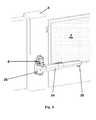
- Figure 1 is a perspective view of an actuator of the invention installed between a pillar of an entrance door gate and the door panel hinged to it,
- Figure 2 is a partially sectioned enlarged detailed perspective view of the mechanical coupling between the motor exit shaft and the lead screw which operates the lead nut.
- As can be seen from the figures, the actuator of the invention is intended to move a
door panel 2 hinged to a fixed structure consisting for example of apillar 4. It comprises anelectric motor 6 provided with an encoder and supported by theupper arm 8 of a C-shaped bracket 10 fixed by its vertically disposedcentral arm 12 to a vertical surface of thepillar 4 byscrews 14. The vertical exit shaft of themotor 6 extends lowerly, within the space defined by theupper arm 8 and lower arm 8' of thebracket 10, as a vertically disposedlead screw 16 coupled to ahelical ring gear 18. Thisring gear 18 is keyed onto ahorizontal shaft 20 supported via bearings 22 by thecasing 24 of thearm 24 connected to thedoor panel 2. Specifically, this casing, which consists of two half-shells preferably made of die-cast aluminium or plastic material and connected together, is hinged about the axis of theshaft 20 to acylindrical casing 26 housing the entire mechanical speed reduction coupling unit between thelead screw 16 and ahorizontal lead screw 28 engaging in a threaded bush or lead nut (not shown in the drawings) which is hinged about a vertical axis to abracket 30 fixed to thedoor panel 2. - This mechanical speed reduction coupling unit housed in the
cylindrical casing 26 not only comprises thelead screw 16 and thehelical gear 18 but also comprises abevel gear 32 keyed onto theshaft 20 and engaging abevel gear 34 of the same diameter keyed onto thelead screw 28. - The operation of the actuator of the invention is immediately apparent from the aforegoing description: rotating the
motor 6 rotates thelead screw 16 which, by virtue of its engagement with thehelical gear 18, causes theshaft 20 to rotate. This rotates thebevel gear 32 which, by virtue of its engagement with thegear 34, rotates thelead screw 28. The rotation of thelead screw 28 causes the lead nut to slide along it axially and which, being hinged to thedoor panel 2, causes this to move in one or other direction, depending on the direction of rotation of theelectric motor 6. - From the aforegoing it is apparent that the actuator of the invention is particularly advantageous compared with traditional actuators, in that:
- installing the
motor 6 directly on thepillar 4 eliminates floating cables and any movement thereof during operation of thedoor panel 2, - the
fixed motor 6 has non limit to its dimensions, and is completely hidden by thepillar 4 when viewed from the outside, - the elimination of dimension limits on the
motor 6 eliminates virtually any limit to its power, - the elimination of dimension limits on the
motor 6 and the elimination of floating cables means that motors can be provided with a control system and encoder or limit switch on board, - the degree of freedom between the
lead screw 16 andhelical gear 18 about the axis of thelead screw 16 also constitutes the articulation between the door panel operating arm and themotor 6, and hence thepillar 4, making the actuator usable for both right handed and left handed applications, - the degree of freedom between the two
bevel gears shaft 20 also enable the door panel operating arm to move in a vertical plane and hence compensate any installation irregularities of thedoor panel 2 and/ormotor 6 which lead to imperfect parallelism between the axis of themotor 6 and the hinging axis of thedoor panel 2, - the operating arm for the
door panel 2 has only to house thelead screw 28 and is therefore much slimmer than traditional actuators, - the fixing of the actuator to the support structure no longer requires the use of a fork-type bracket, as in the past, hence the inevitable slack due thereto is completely eliminated.
Claims (8)
- An electromechanical actuator for a door panel hinged to a fixed structure, characterised by comprising:- an electric motor (6) with its casing rigidly fixable to said structure (4),- a lead nut hinged to the door panel (2) to be moved,- a lead screw (28) engaging said lead nut,- a mechanical speed reduction coupling between the end of said lead screw (28) and the exit shaft of the motor (6), said mechanical coupling having a first degree of freedom about a substantially vertical axis and a second degree of freedom about a substantially horizontal axis perpendicular to the axis of said lead screw (28).
- An actuator as claimed in claim 1, characterised in that said lead screw (28) is housed in a casing.
- An actuator as claimed in claim 1, characterised in that said mechanical coupling comprises a lead screw (16) rigid with the shaft of the motor (6) and a helical gear (18) keyed onto a substantially vertical shaft (20) on which a first bevel gear (32) is keyed, engaging a second bevel gear (34) keyed onto the lead screw (28) of the operating arm.
- An actuator as claimed in claim 1, characterised in that the shaft (20) of said helical gear (18) is supported by support bearings (22) provided in a coupling casing (24, 26) housing the speed reduction unit (16, 18) and the bevel gear pair (32, 34).
- An actuator as claimed in claims 2 and 4, characterised in that the casing (24) housing the lead screw (28) of the operating arm is hinged by a form fit to the casing (26) housing the speed reduction unit (16, 18) and the two bevel gears (32, 34).
- An actuator as claimed in claims 1 and 4, characterised by comprising, for fixing the motor (6) to the fixed structure (4), a C-shaped bracket (10) with a central plate (12) for its fixing to said structure (4) and with two horizontal plates (8, 8') rigid with said central plate (12), the electric motor (6) being fixed upperly to the upper plate (8), and the casing (26) housing the mechanical speed reduction coupling unit being interposed between the two plates (8, 8').
- An actuator as claimed in claim 3, characterised in that the two bevel gears (32, 34) have the same diameter.
- An actuator as claimed in claim 1, characterised in that the motor (6) is provided with an encoder.
Applications Claiming Priority (1)
| Application Number | Priority Date | Filing Date | Title |
|---|---|---|---|
| ITVE20050044 ITVE20050044A1 (en) | 2005-09-23 | 2005-09-23 | ELECTROMECHANICAL ACTUATOR FOR ARTICULATED DOOR. |
Publications (1)
| Publication Number | Publication Date |
|---|---|
| EP1770237A2 true EP1770237A2 (en) | 2007-04-04 |
Family
ID=37499280
Family Applications (1)
| Application Number | Title | Priority Date | Filing Date |
|---|---|---|---|
| EP20060120747 Withdrawn EP1770237A2 (en) | 2005-09-23 | 2006-09-15 | Electromechanical actuator for a hinged door panel |
Country Status (2)
| Country | Link |
|---|---|
| EP (1) | EP1770237A2 (en) |
| IT (1) | ITVE20050044A1 (en) |
Cited By (4)
| Publication number | Priority date | Publication date | Assignee | Title |
|---|---|---|---|---|
| RU2371562C1 (en) * | 2008-07-07 | 2009-10-27 | Игорь Брониславович Подсядло | Device for opening and closing of folds |
| ITAN20090097A1 (en) * | 2009-12-02 | 2011-06-03 | Rovinelli Bruno Srl | APPARATUS FOR MECHANIZED OPERATION OF A GATE OR GATE DOOR. |
| EP2116681A3 (en) * | 2008-05-09 | 2014-03-19 | Nice S.P.A. | Limit stop device for an electromechanical actuator for moving doors, main entrance doors, gates or the like |
| CN111206842A (en) * | 2018-11-22 | 2020-05-29 | 斯泰必鲁斯股份有限公司 | Vehicle turning plate movement mechanism |
-
2005
- 2005-09-23 IT ITVE20050044 patent/ITVE20050044A1/en unknown
-
2006
- 2006-09-15 EP EP20060120747 patent/EP1770237A2/en not_active Withdrawn
Cited By (8)
| Publication number | Priority date | Publication date | Assignee | Title |
|---|---|---|---|---|
| EP2116681A3 (en) * | 2008-05-09 | 2014-03-19 | Nice S.P.A. | Limit stop device for an electromechanical actuator for moving doors, main entrance doors, gates or the like |
| RU2371562C1 (en) * | 2008-07-07 | 2009-10-27 | Игорь Брониславович Подсядло | Device for opening and closing of folds |
| ITAN20090097A1 (en) * | 2009-12-02 | 2011-06-03 | Rovinelli Bruno Srl | APPARATUS FOR MECHANIZED OPERATION OF A GATE OR GATE DOOR. |
| CN111206842A (en) * | 2018-11-22 | 2020-05-29 | 斯泰必鲁斯股份有限公司 | Vehicle turning plate movement mechanism |
| EP3656960A3 (en) * | 2018-11-22 | 2020-07-29 | STABILUS GmbH | Vehicle hatch kinematics |
| CN111206842B (en) * | 2018-11-22 | 2023-06-02 | 斯泰必鲁斯股份有限公司 | Vehicle turning plate movement mechanism |
| JP7424804B2 (en) | 2018-11-22 | 2024-01-30 | シュタビルス ゲゼルシャフト ミット ベシュレンクテル ハフツング | Operating mechanism for vehicle flaps |
| US12110724B2 (en) | 2018-11-22 | 2024-10-08 | Stabilus Gmbh | Actuator for vehicle flap |
Also Published As
| Publication number | Publication date |
|---|---|
| ITVE20050044A1 (en) | 2007-03-24 |
Similar Documents
| Publication | Publication Date | Title |
|---|---|---|
| US7578096B2 (en) | Apparatus for movable separating elements, a drive assembly and a separating element | |
| EP2527579B1 (en) | Linear actuator particularly for sliding doors and for sliding doors and windows in general | |
| TWI510703B (en) | Antriebseinrichtung fuer einen beschlag | |
| AU2008248881B2 (en) | Panel fitting | |
| US5309677A (en) | Electrically operated vehicle window | |
| GB2338028A (en) | Powered door operator | |
| US7971391B2 (en) | Movable body driving apparatus | |
| CN110664140A (en) | Improved electric sliding rail | |
| US5313737A (en) | Powered window operator drive | |
| EP1770237A2 (en) | Electromechanical actuator for a hinged door panel | |
| JP2009264006A (en) | Moving body driving device | |
| DE50109612D1 (en) | Ceiling mount unit | |
| CN1692208A (en) | Door electromechanical operator | |
| AU2010101382A4 (en) | Roller Door Drive Assembly | |
| CN1131971C (en) | Electric drive device | |
| JP2011017190A (en) | Opening and closing apparatus, and window using the same | |
| KR101150813B1 (en) | A door opening and closing unit and a sliding door system having a lower driving noise | |
| EP1903256B1 (en) | Powered swivel drive | |
| EP2754827A2 (en) | Operating assembly for use with automatic sliding and folding doors | |
| JP6014888B2 (en) | Vehicle door opening and closing drive device | |
| KR101511121B1 (en) | Compact rotary device | |
| EP3715176B1 (en) | Drive unit for a slide-out room | |
| DE102007054462B4 (en) | Door drive with an angle detection of the closer shaft | |
| CN120421939B (en) | Feeding manipulator for electric vehicle assembly | |
| EP0713032A2 (en) | An electromechanical linear actuator for driving wing closing systems |
Legal Events
| Date | Code | Title | Description |
|---|---|---|---|
| PUAI | Public reference made under article 153(3) epc to a published international application that has entered the european phase |
Free format text: ORIGINAL CODE: 0009012 |
|
| AK | Designated contracting states |
Kind code of ref document: A2 Designated state(s): AT BE BG CH CY CZ DE DK EE ES FI FR GB GR HU IE IS IT LI LT LU LV MC NL PL PT RO SE SI SK TR |
|
| AX | Request for extension of the european patent |
Extension state: AL BA HR MK YU |
|
| RAP1 | Party data changed (applicant data changed or rights of an application transferred) |
Owner name: MOX MOTION GATES S.N.C. DI FLORIAN DINO & C. |
|
| STAA | Information on the status of an ep patent application or granted ep patent |
Free format text: STATUS: THE APPLICATION IS DEEMED TO BE WITHDRAWN |
|
| 18D | Application deemed to be withdrawn |
Effective date: 20110401 |