EP1770222A1 - Working machine - Google Patents
Working machine Download PDFInfo
- Publication number
- EP1770222A1 EP1770222A1 EP06120126A EP06120126A EP1770222A1 EP 1770222 A1 EP1770222 A1 EP 1770222A1 EP 06120126 A EP06120126 A EP 06120126A EP 06120126 A EP06120126 A EP 06120126A EP 1770222 A1 EP1770222 A1 EP 1770222A1
- Authority
- EP
- European Patent Office
- Prior art keywords
- operator seat
- protective
- frame
- pillar
- working machine
- Prior art date
- Legal status (The legal status is an assumption and is not a legal conclusion. Google has not performed a legal analysis and makes no representation as to the accuracy of the status listed.)
- Withdrawn
Links
Images


Classifications
-
- B—PERFORMING OPERATIONS; TRANSPORTING
- B62—LAND VEHICLES FOR TRAVELLING OTHERWISE THAN ON RAILS
- B62D—MOTOR VEHICLES; TRAILERS
- B62D33/00—Superstructures for load-carrying vehicles
- B62D33/06—Drivers' cabs
- B62D33/063—Drivers' cabs movable from one position into at least one other position, e.g. tiltable, pivotable about a vertical axis, displaceable from one side of the vehicle to the other
- B62D33/0633—Drivers' cabs movable from one position into at least one other position, e.g. tiltable, pivotable about a vertical axis, displaceable from one side of the vehicle to the other pivotable about a vertical axis
-
- B—PERFORMING OPERATIONS; TRANSPORTING
- B60—VEHICLES IN GENERAL
- B60R—VEHICLES, VEHICLE FITTINGS, OR VEHICLE PARTS, NOT OTHERWISE PROVIDED FOR
- B60R21/00—Arrangements or fittings on vehicles for protecting or preventing injuries to occupants or pedestrians in case of accidents or other traffic risks
- B60R21/02—Occupant safety arrangements or fittings, e.g. crash pads
- B60R21/13—Roll-over protection
- B60R21/131—Protective devices for drivers in case of overturning of tractors
-
- E—FIXED CONSTRUCTIONS
- E02—HYDRAULIC ENGINEERING; FOUNDATIONS; SOIL SHIFTING
- E02F—DREDGING; SOIL-SHIFTING
- E02F3/00—Dredgers; Soil-shifting machines
- E02F3/04—Dredgers; Soil-shifting machines mechanically-driven
- E02F3/28—Dredgers; Soil-shifting machines mechanically-driven with digging tools mounted on a dipper- or bucket-arm, i.e. there is either one arm or a pair of arms, e.g. dippers, buckets
- E02F3/30—Dredgers; Soil-shifting machines mechanically-driven with digging tools mounted on a dipper- or bucket-arm, i.e. there is either one arm or a pair of arms, e.g. dippers, buckets with a dipper-arm pivoted on a cantilever beam, i.e. boom
- E02F3/32—Dredgers; Soil-shifting machines mechanically-driven with digging tools mounted on a dipper- or bucket-arm, i.e. there is either one arm or a pair of arms, e.g. dippers, buckets with a dipper-arm pivoted on a cantilever beam, i.e. boom working downwardly and towards the machine, e.g. with backhoes
- E02F3/325—Backhoes of the miniature type
-
- E—FIXED CONSTRUCTIONS
- E02—HYDRAULIC ENGINEERING; FOUNDATIONS; SOIL SHIFTING
- E02F—DREDGING; SOIL-SHIFTING
- E02F9/00—Component parts of dredgers or soil-shifting machines, not restricted to one of the kinds covered by groups E02F3/00 - E02F7/00
- E02F9/16—Cabins, platforms, or the like, for drivers
- E02F9/163—Structures to protect drivers, e.g. cabins, doors for cabins; Falling object protection structure [FOPS]; Roll over protection structure [ROPS]
-
- B—PERFORMING OPERATIONS; TRANSPORTING
- B60—VEHICLES IN GENERAL
- B60R—VEHICLES, VEHICLE FITTINGS, OR VEHICLE PARTS, NOT OTHERWISE PROVIDED FOR
- B60R21/00—Arrangements or fittings on vehicles for protecting or preventing injuries to occupants or pedestrians in case of accidents or other traffic risks
- B60R2021/0065—Type of vehicles
- B60R2021/0074—Utility vehicles
- B60R2021/0081—Working vehicles
Definitions
- the present invention relates to a working machine, particularly a small-sized working machine, having a canopy structure wherein an operator seat is open to the exterior.
- a mini-excavator having a lower traveling body, an upper rotating body mounted rotatably on the lower traveling body, and an operator seat mounted on device covers of the upper rotating body.
- driving devices such as a working oil tank for operating the excavator and a fuel tank are installed within a device cover disposed at right and left positions of the operator seat, so in order to ensure support pillar erecting space on a rotating frame with those devices mounted thereon, it is necessary to for example change a layout of those devices. Consequently, working efficiency for maintenance of those devices is sacrificed.
- the working machine having a canopy structure according to the present invention has the following basic configuration.
- the working machine of the present invention comprises a lower traveling body, an upper rotating body mounted rotatably on the lower traveling body, an operator seat disposed on top of a rotating frame of the upper rotating body, and a protective pillar erected on the rotating frame to protect the operator seat sideways.
- the protective pillar comprises a protective portion extending substantially vertically in front of a back rest of the operator seat so as to cover the operator seat sideways, a fixing portion fixed onto the rotating frame at a position behind the operator seat, and a connecting portion adapted to extend forward from the fixing portion and to be connected to a lower end of the protective portion.
- the protective portion is disposed within a range of a seating surface of the operator seat in side view and is formed upward from a position lower than an upper end of the back rest.
- the protective portion is contiguous to the connecting portion adapted to extend forward from the fixing portion which is fixed onto the rotating frame at a position behind the operator seat, the operator seat can be protected sideways by the protective portion.
- the protective pillar can be disposed by utilizing the space behind the operator seat which has heretofore been ensured without changing the layout of driving devices on the rotating frame or the like.
- the protective pillar can be mounted without changing the layout of driving devices on the rotating frame or the like. Consequently, even in the event that the working machine should turn sideways, it is possible to protect the operator seat while ensuring the workability for maintenance of the driving devices.
- extending forward in connection with the connecting portion is meant to include not only extending in the horizontal direction but also tilting in the vertical or transverse direction.
- the above canopy structure is further provided with an upper protective frame which is held above the operator seat, and an upper end of the protective portion is connected to the upper protective frame.
- the driver seat can be protected sideways in a vertical range from a position lower than the upper end of the back rest up to the upper protective frame.
- the rotating frame is provided with a frame body secured to the lower traveling body and a support frame projected on the frame body to support the operator seat, and the fixing portion is fixed to an upper portion of the support frame.
- the overall length of the protective pillar can be made shorter than in case of fixing the fixing portion to the frame body and therefore the sectional area of the protective pillar necessary for ensuring the same strength can be so much decreased. Consequently, not only the operator's sight can be ensured to a satisfactory extent but also the cost of the protective pillar can be reduced as a result of shortening of the overall length and decrease of the sectional area.
- the attitude of the fixing portion at the time of mounting the rotating frame is not specially limited, but preferably the fixing portion is fixed to the rotating frame in an attitude such that the axis thereof is orthogonal to the vertical direction and an advancing direction of the lower traveling body.
- an external force applied when the working machine turns sideways an external force which the protective pillar undergoes upon collision thereof with the ground
- an external force which the protective pillar undergoes upon collision thereof with the ground is inputted in the axial direction of the fixing portion.
- the operator seat can be protected from one side by forming at least one of the pillar members as a protective pillar. Further, the operator seat can be protected from both right and left sides by forming both pillar members as protective pillars.
- the upper protective frame be supported by a front support pillar and the pillar members, the front support pillar being erected on the rotating frame in front of the operator seat.
- the external force inputted to the protective portion when the working machine turns sideways can be dispersed through the upper protective frame to the pillar members and the front support pillar. Therefore, out of the pillar members and the front support pillar, one which undergoes the external force (one which comes into collision with the ground when the working machine turns sideways) is prevented from being deformed to an extreme extent and the operator seat can thereby be protected in a more positive manner.
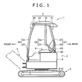
- Fig. 1 is a side view showing a configuration of a small-sized hydraulic excavator to which a canopy structure according to the present invention is applied.
- an upper rotating body 3 is mounted rotatably on a crawler type lower traveling body 2 and a front attachment 4 is provided on a front side of the upper rotating body 3.
- the front attachment 4 is mainly composed of a boom, an arm, a bucket, and a hydraulic cylinder for actuating those members.
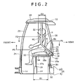
- Fig. 2 is a side view showing a frame structure of the upper rotating body 3 shown in Fig. 1.
- the upper rotating body 3 includes a rotating frame 5 mounted rotatably on the lower traveling body 2, as well as components mounted on the rotating frame 5, which are an operator seat 6, a canopy 7, and a device cover 8.
- the rotating frame 5 mounted rotatably on the lower traveling body 2, as well as components mounted on the rotating frame 5, which are an operator seat 6, a canopy 7, and a device cover 8.
- the right and left direction is the transverse direction of the small-sized hydraulic excavator 1.
- the rotating frame 5 includes a frame body 9 mounted rotatably on the lower traveling body 2 and a seat stand (support frame) 10 projected from an upper rear portion of the frame body 9.
- the frame body 9 is a generally rectangular plate member extending in the longitudinal direction. On the frame body 9 there are erected a front pedestal 11 along a front edge, a pair of mounting portions 12 (only one is shown in Fig. 2) arranged right and left along the rear edge, and a rear pedestal 14 extending right and left between the pedestal 11 and the mounting portions 12.
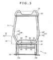
- Fig. 3 is a rear view showing the rotating frame 5 of the upper rotating body 3 shown in Fig. 2 in an omitted state.
- Fig. 4 is a perspective view of the upper rotating body 3 shown in Fig. 3.
- Fig. 5 is a perspective view showing the enlarged seat stand 10.
- the seat stand 10 is a generally rectangular frame mounted on the mounting portions 12 and the rear pedestal 14.
- the seat stand 10 supports the operator seat 6 thereon.
- the seat stand 10 includes a pair of left and right rear legs 15a and 15b secured with bolts B1 to the mounting portions 12, a seat plate 16 mounted on the rear pedestal 14, a pair of left and right front legs 17a and 17b erected on the seat plate 16, a pair of left and right upper-side portions 18a and 18b which provide connections between upper portions of the front legs 17a and 17b and upper portions of the rear legs 15a and 15b, and a mounting plate 19 which connects upper ends of the rear legs 15a and 15b with each other.
- the upper-side portions 18a and 18b are formed by rearward bending of the front legs 17a and 17b.
- the upper-side portions 18a and 18b of the seat stand 10 support the operator seat 6. That is, the mounting plate 19 is disposed behind the operator seat 6.
- the canopy 7 includes a front support pillar 20 erected on the front pedestal 11, a support member 21 mounted on the mounting plate 19 of the seat stand 10, an upper protective frame 22 which is held above the operator seat 6 by the front support pillar 20 and the support member 21, and a roof 35 which covers the upper protective frame 22.
- the front support pillar 20 includes a support pillar body 23 erected on a right upper surface of the front pedestal 11 and a handrail portion 24, the handrail portion 24 extending leftwards from an intermediate portion of the support pillar body 23 and being bent downward and fixed to a left upper surface of the front pedestal 11.
- the upper protective frame 22 is supported by an upper end portion of the support pillar body 23.
- the support member 21 is a single metallic pipe fixed onto the mounting plate 19 through a tubular member 25.
- the tubular member 25 is fixed onto the mounting plate 19 with a pair of right and left bolts B3 in an attitude of its axis facing in the transverse direction.
- the support member 21 includes a fixing portion 26 which is inserted into the tubular member 25 and a right support pillar 27 and a left support pillar 28 which are bent upward from both right and left sides of the tubular member 25.
- the right support pillar 27 includes a rising portion 29 which extends upward from the mounting plate 19 while expanding rightwards and a connecting portion 30, the connecting portion 30 tilting forward from an upper end of the rising portion 29 while bending, or closing, leftwards and being connected to the upper protective frame 22.
- the left support pillar 28 includes a connecting portion 31, the connecting portion 31 tilting forward from the mounting plate 19 while expanding leftwards and extending up to sideways of the left side of the operator seat 6, and a protective portion 32, the protective portion 32 extending upward from an upper end of the connecting portion 31 while bending, or closing, rightwards and being connected to the upper protective frame 22.
- the protective portion 32 is disposed within a range D1 of a seating surface 6a of the operator seat 6 and within an upper range from a position lower than an upper end position P1 of a back rest 6b of the operator seat 6. Therefore, even in the event that the small-sized hydraulic excavator 1 should turn sideways, the operator H can be protected from the left side by the protective portion 32.
- the protective portion 32 be disposed within a thickness range D2 of an upper half of a body of the operator H sitting on the operator seat 6 and that a lower end of the protective portion 32 be located at a position lower than a height position P2 of a shoulder H1 of the operator H. With this arrangement, a head of the operator H can be protected positively by the protective portion 32.
- a control box 33 for actuating the front attachment 4 is disposed on the left side of the operator seat 6, as shown in Figs. 2 and 3, it is preferable that the protective portion 32 be located in an upper range with respect to an upper position P3 of the control box 33.
- the operator H can be protected from the left side by the control box 33 with respect to the range lower than the upper position P3 and can be protected from the left side by the protective portion 32 with respect to a range higher than the upper position P3.
- the device cover 8 is mounted on the rotating frame 5 so as to incorporate various driving devices (e.g., a working oil tank 34) mounted on the rotating frame 5 and surround the rear and side portions of the seat stand 10.
- various driving devices e.g., a working oil tank 34
- the working oil tank 34 is disposed on the left side of the seat stand 10.
- the upper protective film 22 is frame-shaped in plan as in Fig. 4 and is connected to upper ends of the support pillar body 23, the right support pillar 27 and the left support pillar 28, with the roof 35 as a synthetic resin roof mounted thereon. No limitation is made to configuring the upper protective frame 22 and the roof 35 separately, but both may be formed integrally.
- the protective portion 32 contiguously to the connecting portion 31 extending forward from the fixing portion 26 which is fixed onto the rotating frame 5 at a position behind the operator seat 6, the operator seat 6 can be protected sideways by the protective portion 32.
- the left support pillar (protective pillar) 28 can be disposed by utilizing the space at a position behind the operator seat 6 which space has heretofore been ensured, without changing the layout of the working oil tank 34 on the rotating frame 5 or the like.
- the left support pillar 28 can be installed without changing the layout of the working oil tank 34 on the rotating frame 5 or the like. Consequently, in the event that the working machine should turn sideways, it is possible to protect the operator seat 6 while keeping the working efficiency for maintenance of the working oil tank 34 to a satisfactory extent.
- the overall length of the left support pillar 28 can be made shorter than in case of fixing the fixing portion 26 to the frame body 9, and hence a sectional area of the left support pillar 28 necessary for ensuring the same strength can be so much decreased.
- cost of the left support pillar 28 can be reduced by the shortening of the overall length and the decrease of the sectional area.
- the fixing portion 26 is fixed to the rotating frame 5 in an attitude of its axis facing in the transverse direction (the direction orthogonal to the vertical and longitudinal directions)
- an external force applied when the working machine turns sideways an external force which the left support pillar 28 undergoes upon collision with the ground
- the left support pillar 28 can be prevented from undergoing a flexural deformation in the fixing portion (fixing portion 26) fixed to the rotating frame 5 due to the external force.
- protective strength of the operator seat 6 can be further improved.
- the connecting portion 31 and the protective portion 32 are provided for the left support pillar 28 out of the pair of right and left support pillars 27 and 28 erected at a position behind the operator seat 6, the connecting portion 31 and the protective portion 32 may be provided for each of the right and left support pillars 27 and 28. By so doing, the operator seat 6 can be protected from both right and left sides by the right and left support pillars 27, 28.
- either the right support pillar 27 or the left support pillar 28 be provided with the protective portion 32, taking into account the case where the working machine turns sideways to at least the offset side.
- the external force which is inputted to the protective portion 32 when the working machine turns sideways can be dispersed to the front and right support pillars 20 and 27 through the upper protective frame 22. Therefore, it is possible to prevent the left support pillar 28 from being deformed to an extreme extent due to the external force and hence possible to protect the operator seat 6 in a more positive manner.
- a left support pillar includes a protective portion extending substantially vertically in front of a back rest of the operator seat so as to cover an operator seat sideways, a fixing portion fixed onto a rotating frame at a position behind the operator seat, and a connecting portion adapted to extend forward from the fixing portion and to be connected to a lower end of the protective portion.
- the protective portion is disposed within a predetermined range of a seating surface of the operator seat and is formed upward from a position lower than an upper end of the back rest.
Landscapes
- Engineering & Computer Science (AREA)
- Mechanical Engineering (AREA)
- Mining & Mineral Resources (AREA)
- Civil Engineering (AREA)
- General Engineering & Computer Science (AREA)
- Structural Engineering (AREA)
- Chemical & Material Sciences (AREA)
- Combustion & Propulsion (AREA)
- Transportation (AREA)
- Component Parts Of Construction Machinery (AREA)
- Body Structure For Vehicles (AREA)
Abstract
Description
- The present invention relates to a working machine, particularly a small-sized working machine, having a canopy structure wherein an operator seat is open to the exterior.
- Heretofore, as a small-sized working machine there has been known what is called a mini-excavator having a lower traveling body, an upper rotating body mounted rotatably on the lower traveling body, and an operator seat mounted on device covers of the upper rotating body.
- For example, in
Japanese Patent Laid-Open No. 2001-279718 - In this type of a mini-excavator it is desirable to erect support pillars sideways of the operator seat in order to protect the operator seat which is open to the exterior in the event that the mini-excavator should turn sideways.
- However, in the mini-excavator in question, it has so far been difficult to ensure a space for erecting the support pillars sideways of the operator seat.
- More particularly, driving devices such as a working oil tank for operating the excavator and a fuel tank are installed within a device cover disposed at right and left positions of the operator seat, so in order to ensure support pillar erecting space on a rotating frame with those devices mounted thereon, it is necessary to for example change a layout of those devices. Consequently, working efficiency for maintenance of those devices is sacrificed.
- It may be effective to erect the support pillars directly on the device cover. However, also in this case, there arises the necessity of restricting for example opening/closing directions of the device cover, with a consequent likelihood of causing deterioration in the working efficiency for maintenance of the driving devices.
- It is an object of the present invention to provide a working machine, especially a small-sized working machine, having a canopy structure capable of protecting an operator seat while keeping working efficiency for maintenance to a satisfactory extent.
- The working machine having a canopy structure according to the present invention has the following basic configuration.
- That is, the working machine of the present invention comprises a lower traveling body, an upper rotating body mounted rotatably on the lower traveling body, an operator seat disposed on top of a rotating frame of the upper rotating body, and a protective pillar erected on the rotating frame to protect the operator seat sideways. The protective pillar comprises a protective portion extending substantially vertically in front of a back rest of the operator seat so as to cover the operator seat sideways, a fixing portion fixed onto the rotating frame at a position behind the operator seat, and a connecting portion adapted to extend forward from the fixing portion and to be connected to a lower end of the protective portion. The protective portion is disposed within a range of a seating surface of the operator seat in side view and is formed upward from a position lower than an upper end of the back rest.
- According to the present invention, since the protective portion is contiguous to the connecting portion adapted to extend forward from the fixing portion which is fixed onto the rotating frame at a position behind the operator seat, the operator seat can be protected sideways by the protective portion. Thus, unlike the case where a support pillar is provided directly onto the rotating frame, the protective pillar can be disposed by utilizing the space behind the operator seat which has heretofore been ensured without changing the layout of driving devices on the rotating frame or the like.
- Therefore, according to the present invention, even in the case where the space formed on the rotating frame and sideways of the operator seat is limited, the protective pillar can be mounted without changing the layout of driving devices on the rotating frame or the like. Consequently, even in the event that the working machine should turn sideways, it is possible to protect the operator seat while ensuring the workability for maintenance of the driving devices.
- By "extending forward" in connection with the connecting portion is meant to include not only extending in the horizontal direction but also tilting in the vertical or transverse direction.
- Preferably, the above canopy structure is further provided with an upper protective frame which is held above the operator seat, and an upper end of the protective portion is connected to the upper protective frame.
- In this case, the driver seat can be protected sideways in a vertical range from a position lower than the upper end of the back rest up to the upper protective frame.
- Preferably, the rotating frame is provided with a frame body secured to the lower traveling body and a support frame projected on the frame body to support the operator seat, and the fixing portion is fixed to an upper portion of the support frame.
- In this case, since the fixing portion is fixed to the upper portion of the support frame, the overall length of the protective pillar can be made shorter than in case of fixing the fixing portion to the frame body and therefore the sectional area of the protective pillar necessary for ensuring the same strength can be so much decreased. Consequently, not only the operator's sight can be ensured to a satisfactory extent but also the cost of the protective pillar can be reduced as a result of shortening of the overall length and decrease of the sectional area.
- The attitude of the fixing portion at the time of mounting the rotating frame is not specially limited, but preferably the fixing portion is fixed to the rotating frame in an attitude such that the axis thereof is orthogonal to the vertical direction and an advancing direction of the lower traveling body.
- In this case, an external force applied when the working machine turns sideways (an external force which the protective pillar undergoes upon collision thereof with the ground) is inputted in the axial direction of the fixing portion. Thus, it is possible to prevent the protective pillar from undergoing a flexural deformation in the fixing portion for the rotating frame due to the external force and hence possible to further improve the strength of protection for the operator seat.
- In case of erecting a pair of right and left pillar members on the rotating frame and at a position behind the operator seat, the operator seat can be protected from one side by forming at least one of the pillar members as a protective pillar. Further, the operator seat can be protected from both right and left sides by forming both pillar members as protective pillars.
- In this case, it is further preferable that the upper protective frame be supported by a front support pillar and the pillar members, the front support pillar being erected on the rotating frame in front of the operator seat.
- In this case, the external force inputted to the protective portion when the working machine turns sideways can be dispersed through the upper protective frame to the pillar members and the front support pillar. Therefore, out of the pillar members and the front support pillar, one which undergoes the external force (one which comes into collision with the ground when the working machine turns sideways) is prevented from being deformed to an extreme extent and the operator seat can thereby be protected in a more positive manner.
-
- Fig. 1 is a side view showing a configuration of a small-sized hydraulic excavator to which a canopy structure according to the present invention is applied;
- Fig. 2 is a side view showing a frame structure of an upper rotating body shown in Fig. 1;
- Fig. 3 is a rear view showing a rotating frame of the upper rotating body shown in Fig. 2 in an omitted state;
- Fig. 4 is a perspective view of the upper rotating body shown in Fig. 3; and
- Fig. 5 is a perspective view showing an enlarged seat stand.
- Preferred embodiments of the present invention will be described hereinunder with reference to the drawings.
- Fig. 1 is a side view showing a configuration of a small-sized hydraulic excavator to which a canopy structure according to the present invention is applied.
- In a small-sized
hydraulic excavator 1, as shown in Fig. 1, an upper rotatingbody 3 is mounted rotatably on a crawler type lower travelingbody 2 and a front attachment 4 is provided on a front side of the upper rotatingbody 3. Though not shown, the front attachment 4 is mainly composed of a boom, an arm, a bucket, and a hydraulic cylinder for actuating those members. - Fig. 2 is a side view showing a frame structure of the upper rotating
body 3 shown in Fig. 1. - Referring to Figs. 1 and 2, the upper rotating
body 3 includes a rotatingframe 5 mounted rotatably on the lower travelingbody 2, as well as components mounted on the rotatingframe 5, which are anoperator seat 6, acanopy 7, and adevice cover 8. In the following description it is assumed that, when an operator H sitting on theoperator seat 6 sees the front, the right and left direction is the transverse direction of the small-sizedhydraulic excavator 1. - The rotating
frame 5 includes aframe body 9 mounted rotatably on thelower traveling body 2 and a seat stand (support frame) 10 projected from an upper rear portion of theframe body 9. - The
frame body 9 is a generally rectangular plate member extending in the longitudinal direction. On theframe body 9 there are erected afront pedestal 11 along a front edge, a pair of mounting portions 12 (only one is shown in Fig. 2) arranged right and left along the rear edge, and arear pedestal 14 extending right and left between thepedestal 11 and themounting portions 12. - Fig. 3 is a rear view showing the rotating
frame 5 of the upper rotatingbody 3 shown in Fig. 2 in an omitted state. Fig. 4 is a perspective view of the upper rotatingbody 3 shown in Fig. 3. Fig. 5 is a perspective view showing the enlargedseat stand 10. - Referring to Figs. 2 to 5, the
seat stand 10 is a generally rectangular frame mounted on themounting portions 12 and therear pedestal 14. Theseat stand 10 supports theoperator seat 6 thereon. - More specifically, the
seat stand 10 includes a pair of left and rightrear legs mounting portions 12, aseat plate 16 mounted on therear pedestal 14, a pair of left and rightfront legs seat plate 16, a pair of left and right upper-side portions front legs rear legs mounting plate 19 which connects upper ends of therear legs side portions front legs - The upper-
side portions operator seat 6. That is, themounting plate 19 is disposed behind theoperator seat 6. - The
canopy 7 according to the present invention includes afront support pillar 20 erected on thefront pedestal 11, asupport member 21 mounted on themounting plate 19 of theseat stand 10, an upperprotective frame 22 which is held above theoperator seat 6 by thefront support pillar 20 and thesupport member 21, and aroof 35 which covers the upperprotective frame 22. - The
front support pillar 20 includes asupport pillar body 23 erected on a right upper surface of thefront pedestal 11 and ahandrail portion 24, thehandrail portion 24 extending leftwards from an intermediate portion of thesupport pillar body 23 and being bent downward and fixed to a left upper surface of thefront pedestal 11. The upperprotective frame 22 is supported by an upper end portion of thesupport pillar body 23. - The
support member 21 is a single metallic pipe fixed onto themounting plate 19 through atubular member 25. Thetubular member 25 is fixed onto the mountingplate 19 with a pair of right and left bolts B3 in an attitude of its axis facing in the transverse direction. - More specifically, the
support member 21 includes a fixingportion 26 which is inserted into thetubular member 25 and aright support pillar 27 and aleft support pillar 28 which are bent upward from both right and left sides of thetubular member 25. - With the fixing
portion 26 inserted into thetubular member 25, a nut B2 is brought into threaded engagement with a bolt B3 which extends vertically through thetubular member 25, the fixingportion 26 and the mountingplate 19, whereby the fixingportion 26 is fixed onto the mountingplate 19 in an attitude of its axis facing in the transverse direction. - As shown in Figs. 2 and 3, the
right support pillar 27 includes a risingportion 29 which extends upward from the mountingplate 19 while expanding rightwards and a connectingportion 30, the connectingportion 30 tilting forward from an upper end of the risingportion 29 while bending, or closing, leftwards and being connected to the upperprotective frame 22. - The
left support pillar 28 includes a connectingportion 31, the connectingportion 31 tilting forward from the mountingplate 19 while expanding leftwards and extending up to sideways of the left side of theoperator seat 6, and aprotective portion 32, theprotective portion 32 extending upward from an upper end of the connectingportion 31 while bending, or closing, rightwards and being connected to the upperprotective frame 22. - As shown in the side view of Fig. 2, the
protective portion 32 is disposed within a range D1 of aseating surface 6a of theoperator seat 6 and within an upper range from a position lower than an upper end position P1 of aback rest 6b of theoperator seat 6. Therefore, even in the event that the small-sizedhydraulic excavator 1 should turn sideways, the operator H can be protected from the left side by theprotective portion 32. - More particularly, it is preferable that the
protective portion 32 be disposed within a thickness range D2 of an upper half of a body of the operator H sitting on theoperator seat 6 and that a lower end of theprotective portion 32 be located at a position lower than a height position P2 of a shoulder H1 of the operator H. With this arrangement, a head of the operator H can be protected positively by theprotective portion 32. - In the case where a
control box 33 for actuating the front attachment 4 is disposed on the left side of theoperator seat 6, as shown in Figs. 2 and 3, it is preferable that theprotective portion 32 be located in an upper range with respect to an upper position P3 of thecontrol box 33. With this arrangement, the operator H can be protected from the left side by thecontrol box 33 with respect to the range lower than the upper position P3 and can be protected from the left side by theprotective portion 32 with respect to a range higher than the upper position P3. - Referring to Figs. 1 and 5, the
device cover 8 is mounted on therotating frame 5 so as to incorporate various driving devices (e.g., a working oil tank 34) mounted on therotating frame 5 and surround the rear and side portions of theseat stand 10. In the present embodiment the workingoil tank 34 is disposed on the left side of theseat stand 10. - The upper
protective film 22 is frame-shaped in plan as in Fig. 4 and is connected to upper ends of thesupport pillar body 23, theright support pillar 27 and theleft support pillar 28, with theroof 35 as a synthetic resin roof mounted thereon. No limitation is made to configuring the upperprotective frame 22 and theroof 35 separately, but both may be formed integrally. - According to the small-sized
hydraulic excavator 1, by providing theprotective portion 32 contiguously to the connectingportion 31 extending forward from the fixingportion 26 which is fixed onto therotating frame 5 at a position behind theoperator seat 6, theoperator seat 6 can be protected sideways by theprotective portion 32. Thus, unlike the case where a support pillar is mounted directly on therotating frame 5, the left support pillar (protective pillar) 28 can be disposed by utilizing the space at a position behind theoperator seat 6 which space has heretofore been ensured, without changing the layout of the workingoil tank 34 on therotating frame 5 or the like. - Therefore, according to the small-sized
hydraulic excavator 1, as shown in Fig. 5, even when the space on the left side of theoperator seat 6 and on therotating frame 5 is limited by the workingoil tank 34, theleft support pillar 28 can be installed without changing the layout of the workingoil tank 34 on therotating frame 5 or the like. Consequently, in the event that the working machine should turn sideways, it is possible to protect theoperator seat 6 while keeping the working efficiency for maintenance of the workingoil tank 34 to a satisfactory extent. - Moreover, according to the small-sized
hydraulic excavator 1, since the fixingportion 26 is fixed onto theseat stand 10, the overall length of theleft support pillar 28 can be made shorter than in case of fixing the fixingportion 26 to theframe body 9, and hence a sectional area of theleft support pillar 28 necessary for ensuring the same strength can be so much decreased. As a result, not only the sight of the operator H can be ensured to a satisfactory extent, but also cost of theleft support pillar 28 can be reduced by the shortening of the overall length and the decrease of the sectional area. - According to the small-sized
hydraulic excavator 1 wherein the fixingportion 26 is fixed to therotating frame 5 in an attitude of its axis facing in the transverse direction (the direction orthogonal to the vertical and longitudinal directions), an external force applied when the working machine turns sideways (an external force which theleft support pillar 28 undergoes upon collision with the ground) is inputted in the axial direction of the fixingportion 26. Therefore, theleft support pillar 28 can be prevented from undergoing a flexural deformation in the fixing portion (fixing portion 26) fixed to therotating frame 5 due to the external force. Thus, protective strength of theoperator seat 6 can be further improved. - Although in the small-sized
hydraulic excavator 1 the connectingportion 31 and theprotective portion 32 are provided for theleft support pillar 28 out of the pair of right and leftsupport pillars operator seat 6, the connectingportion 31 and theprotective portion 32 may be provided for each of the right and leftsupport pillars operator seat 6 can be protected from both right and left sides by the right and leftsupport pillars - On the other hand, for example when the
operator seat 6 is offset to either the right or the left of theframe body 9 in plan, it is preferable that either theright support pillar 27 or theleft support pillar 28 be provided with theprotective portion 32, taking into account the case where the working machine turns sideways to at least the offset side. - Further according to the small-sized
hydraulic excavator 1 wherein the upperprotective frame 22 is held above theoperator seat 6 by the front, right and leftsupport pillars protective portion 32 when the working machine turns sideways can be dispersed to the front andright support pillars protective frame 22. Therefore, it is possible to prevent theleft support pillar 28 from being deformed to an extreme extent due to the external force and hence possible to protect theoperator seat 6 in a more positive manner. - Although the invention has been described with reference to the preferred embodiments in the attached figures, it is noted that equivalents may be employed and substitutions made herein without departing from the scope of the invention as recited in the claims.
- A left support pillar includes a protective portion extending substantially vertically in front of a back rest of the operator seat so as to cover an operator seat sideways, a fixing portion fixed onto a rotating frame at a position behind the operator seat, and a connecting portion adapted to extend forward from the fixing portion and to be connected to a lower end of the protective portion. The protective portion is disposed within a predetermined range of a seating surface of the operator seat and is formed upward from a position lower than an upper end of the back rest.
Claims (7)
- A working machine having a canopy structure, comprising:a lower traveling body;an upper rotating body mounted rotatably on said lower traveling body, said upper rotating body having a rotating frame;an operator seat disposed on top of said rotating frame; anda protective pillar erected on said rotating frame to protect said operator seat sideways, said protective pillar comprising:a protective portion extending substantially vertically in front of a back rest of said operator seat so as to cover said operator seat sideways;a fixing portion fixed onto said rotating frame at a position behind said operator seat; anda connecting portion adapted to extend forward from said fixing portion and to be connected to a lower end of said protective portion,wherein said protective portion is disposed within a range of a seating surface of said operator seat in side view and is formed upward from a position lower than an upper end of said back rest.
- The working machine according to claim 1, further comprising an upper protective frame which is held above said operator seat, said upper protective frame being connected to an upper end of said protective portion.
- The working machine according to claim 1, wherein said rotating frame includes a frame body secured to said lower traveling body and a support frame projected on said frame body to support said operator seat, and said fixing portion is fixed to an upper portion of said support frame.
- The working machine according to claim 1, wherein said fixing portion is fixed to said rotating frame in an attitude such that an axis thereof is orthogonal to a vertical direction and an advancing direction of said lower traveling body.
- The working machine according to claim 1, wherein a pair of right and left pillar members are erected on said rotating frame and behind said operator seat, at least one of said pillar members corresponding to said protective pillar.
- The working machine according to claim 5, wherein both said pillar members correspond to said protective pillar.
- The working machine according to claim 5, wherein said upper protective frame is supported by a front support pillar and said pillar members, said front support pillar being erected on said rotating frame in front of said operator seat.
Applications Claiming Priority (1)
| Application Number | Priority Date | Filing Date | Title |
|---|---|---|---|
| JP2005282982A JP4333657B2 (en) | 2005-09-28 | 2005-09-28 | Canopy structure of small work machine |
Publications (1)
| Publication Number | Publication Date |
|---|---|
| EP1770222A1 true EP1770222A1 (en) | 2007-04-04 |
Family
ID=37600988
Family Applications (1)
| Application Number | Title | Priority Date | Filing Date |
|---|---|---|---|
| EP06120126A Withdrawn EP1770222A1 (en) | 2005-09-28 | 2006-09-05 | Working machine |
Country Status (3)
| Country | Link |
|---|---|
| US (1) | US7338113B2 (en) |
| EP (1) | EP1770222A1 (en) |
| JP (1) | JP4333657B2 (en) |
Families Citing this family (11)
| Publication number | Priority date | Publication date | Assignee | Title |
|---|---|---|---|---|
| JP2005350911A (en) * | 2004-06-09 | 2005-12-22 | Komatsu Ltd | Work vehicle |
| JP4233494B2 (en) * | 2004-06-09 | 2009-03-04 | 株式会社小松製作所 | Canopy mounting structure for work vehicle |
| JP4467595B2 (en) * | 2007-03-28 | 2010-05-26 | 株式会社クボタ | Work vehicle canopy equipment |
| JP4952661B2 (en) * | 2008-06-16 | 2012-06-13 | コベルコ建機株式会社 | Construction machinery |
| JP5806986B2 (en) * | 2012-08-01 | 2015-11-10 | 株式会社クボタ | Protective frame for work equipment |
| US8851555B2 (en) * | 2013-02-07 | 2014-10-07 | Caterpillar Inc. | Cab rollover protective structure for enhanced visibility |
| US8702154B1 (en) * | 2013-02-07 | 2014-04-22 | Caterpillar Inc. | Cab frame with integrated rollover protective structure |
| GB2528091B (en) * | 2014-07-09 | 2020-11-25 | Bamford Excavators Ltd | Operator compartment structure |
| USD784899S1 (en) | 2016-01-05 | 2017-04-25 | Exmark Manufacturing Company, Incorporated | Roll-over protective structure |
| JP6924856B2 (en) * | 2016-05-31 | 2021-08-25 | ヤンマーパワーテクノロジー株式会社 | Construction machinery |
| USD1088964S1 (en) * | 2023-08-14 | 2025-08-19 | Zhejiang Taotao Vehicles Co., Ltd. | Truck |
Citations (10)
| Publication number | Priority date | Publication date | Assignee | Title |
|---|---|---|---|---|
| EP0727529A1 (en) * | 1995-02-17 | 1996-08-21 | Kubota Corporation | Backhoe having an engine hood with a driver's seat mounted thereon |
| JPH09296481A (en) * | 1996-05-07 | 1997-11-18 | Komatsu Zenoah Co | Device mounting structure for upper revolving structure in hydraulic excavator |
| JPH10129992A (en) * | 1996-10-30 | 1998-05-19 | Toyota Autom Loom Works Ltd | Cab for industrial vehicle |
| JPH10219740A (en) * | 1998-03-18 | 1998-08-18 | Yanmar Diesel Engine Co Ltd | Slewing service car |
| JPH11269928A (en) | 1998-03-25 | 1999-10-05 | Kubota Corp | Backhoe and backhoe cabin equipment |
| JP2000096619A (en) | 1998-09-17 | 2000-04-04 | Kubota Corp | Air conditioner for traveling vehicles |
| DE20002106U1 (en) | 2000-02-07 | 2000-04-06 | Fritzmeier Systems GmbH & Co., 85655 Großhelfendorf | Security device |
| US20010017462A1 (en) * | 2000-02-29 | 2001-08-30 | Linde Aktiengesellschaft | Restraint system |
| JP2001279718A (en) * | 2000-03-31 | 2001-10-10 | Kobelco Contstruction Machinery Ltd | Canopy structure for hydraulic shovel and small type hydraulic shovel with its canopy |
| US20020149232A1 (en) | 2000-09-18 | 2002-10-17 | Tsuyoshi Sakyo | Cab for construction machinery |
Family Cites Families (18)
| Publication number | Priority date | Publication date | Assignee | Title |
|---|---|---|---|---|
| US2911232A (en) * | 1957-04-22 | 1959-11-03 | Clark Equipment Co | Overhead guard for industrial lift truck |
| DE1267109B (en) * | 1965-12-17 | 1968-04-25 | Fritzmeier Kg Georg | Roll-over protection frame for mobile machines, especially tractors |
| AT380443B (en) * | 1981-08-19 | 1986-05-26 | Steyr Daimler Puch Ag | DRIVER PROTECTION FRAME FOR ARM TRACTORS |
| DE3460643D1 (en) * | 1984-01-30 | 1986-10-16 | Deere & Co | Driver station for a vehicle |
| US4650242A (en) * | 1984-11-26 | 1987-03-17 | Kubuto, Ltd. | Tractor cabin |
| JPS63149271A (en) * | 1986-12-11 | 1988-06-22 | Kubota Ltd | Horizontal control device for upper structure member of running vehicle |
| DE69004287T2 (en) * | 1989-02-16 | 1994-02-24 | Kubota Kk | Hydraulic pipe arrangement for a backhoe. |
| US5842732A (en) * | 1996-11-27 | 1998-12-01 | Daggett, Deceased; Bill E. | Riding lawn mower canopy |
| AR008565A1 (en) * | 1997-02-14 | 2000-02-09 | Consorcio G Grupo Dina S A De C V | A STRUCTURE FOR A CAB APPLICABLE TO MEDIUM TRUCKS AND TRACTOR TRUCKS |
| MXPA97008574A (en) * | 1997-11-07 | 2004-08-23 | Consorcio G Grupo Dina S A De | Ameliorated structure of cab-over cabin for medium-size bus and truck. |
| US6149228A (en) * | 1998-12-09 | 2000-11-21 | Deere & Company | Modular operator enclosure |
| US6189955B1 (en) * | 2000-04-18 | 2001-02-20 | Deere & Company | Operator enclosure for an agricultural tractor |
| US6325449B1 (en) * | 2000-06-08 | 2001-12-04 | Deere & Company | ROPS structure for work vehicle |
| US7001135B2 (en) * | 2003-02-20 | 2006-02-21 | Kobelco Construction Machinery Co., Ltd. | Construction machine |
| JP4415698B2 (en) | 2003-02-20 | 2010-02-17 | コベルコ建機株式会社 | Canopy structure of construction machinery |
| JP4201126B2 (en) * | 2003-04-10 | 2008-12-24 | 株式会社小松製作所 | Construction machinery cab |
| US7290829B2 (en) * | 2004-06-29 | 2007-11-06 | Kubota Corporation | Working vehicle with a cab |
| US7690714B2 (en) * | 2005-08-18 | 2010-04-06 | Michael John Reeves | Lightning protected golf cart |
-
2005
- 2005-09-28 JP JP2005282982A patent/JP4333657B2/en not_active Expired - Fee Related
-
2006
- 2006-09-05 EP EP06120126A patent/EP1770222A1/en not_active Withdrawn
- 2006-09-07 US US11/470,888 patent/US7338113B2/en not_active Expired - Fee Related
Patent Citations (10)
| Publication number | Priority date | Publication date | Assignee | Title |
|---|---|---|---|---|
| EP0727529A1 (en) * | 1995-02-17 | 1996-08-21 | Kubota Corporation | Backhoe having an engine hood with a driver's seat mounted thereon |
| JPH09296481A (en) * | 1996-05-07 | 1997-11-18 | Komatsu Zenoah Co | Device mounting structure for upper revolving structure in hydraulic excavator |
| JPH10129992A (en) * | 1996-10-30 | 1998-05-19 | Toyota Autom Loom Works Ltd | Cab for industrial vehicle |
| JPH10219740A (en) * | 1998-03-18 | 1998-08-18 | Yanmar Diesel Engine Co Ltd | Slewing service car |
| JPH11269928A (en) | 1998-03-25 | 1999-10-05 | Kubota Corp | Backhoe and backhoe cabin equipment |
| JP2000096619A (en) | 1998-09-17 | 2000-04-04 | Kubota Corp | Air conditioner for traveling vehicles |
| DE20002106U1 (en) | 2000-02-07 | 2000-04-06 | Fritzmeier Systems GmbH & Co., 85655 Großhelfendorf | Security device |
| US20010017462A1 (en) * | 2000-02-29 | 2001-08-30 | Linde Aktiengesellschaft | Restraint system |
| JP2001279718A (en) * | 2000-03-31 | 2001-10-10 | Kobelco Contstruction Machinery Ltd | Canopy structure for hydraulic shovel and small type hydraulic shovel with its canopy |
| US20020149232A1 (en) | 2000-09-18 | 2002-10-17 | Tsuyoshi Sakyo | Cab for construction machinery |
Also Published As
| Publication number | Publication date |
|---|---|
| JP2007091032A (en) | 2007-04-12 |
| US20070069551A1 (en) | 2007-03-29 |
| JP4333657B2 (en) | 2009-09-16 |
| US7338113B2 (en) | 2008-03-04 |
Similar Documents
| Publication | Publication Date | Title |
|---|---|---|
| US11203853B2 (en) | Cabin assembly for construction equipment | |
| US7338113B2 (en) | Working machine | |
| US7665801B2 (en) | Structure of upper frame for supporting cabin of construction machinery | |
| US20150056052A1 (en) | Construction machine | |
| JP2005023718A (en) | Construction machinery | |
| KR101007858B1 (en) | Cab of construction machinery | |
| JP2001173017A (en) | Construction machinery | |
| US20190193557A1 (en) | Resin-Made Fuel Tank Mounting Structure And Construction Machine | |
| CN105637151B (en) | Hydraulic excavator | |
| JP4504283B2 (en) | Construction machinery | |
| JP2007205100A (en) | Body frame of construction machinery and the construction machinery | |
| JP4156973B2 (en) | Cab interior reinforcement structure | |
| JP2007063839A (en) | Protection structure for construction equipment, and cab for construction equipment | |
| CN1965130B (en) | Canopy installation structure in working vehicle | |
| JP4199173B2 (en) | Swivel construction machine | |
| KR101688499B1 (en) | Construction machine | |
| JP5240851B2 (en) | Work machine | |
| JP2002188176A (en) | Construction equipment | |
| JP2007046233A (en) | Construction machine | |
| JP2017002646A5 (en) | ||
| JP2000064356A (en) | Construction machinery | |
| JP4295003B2 (en) | Cab protection structure | |
| CN221142907U (en) | Excavator | |
| JP4415698B2 (en) | Canopy structure of construction machinery | |
| WO2018101148A1 (en) | Construction machinery |
Legal Events
| Date | Code | Title | Description |
|---|---|---|---|
| PUAI | Public reference made under article 153(3) epc to a published international application that has entered the european phase |
Free format text: ORIGINAL CODE: 0009012 |
|
| 17P | Request for examination filed |
Effective date: 20060905 |
|
| AK | Designated contracting states |
Kind code of ref document: A1 Designated state(s): AT BE BG CH CY CZ DE DK EE ES FI FR GB GR HU IE IS IT LI LT LU LV MC NL PL PT RO SE SI SK TR |
|
| AX | Request for extension of the european patent |
Extension state: AL BA HR MK YU |
|
| 17Q | First examination report despatched |
Effective date: 20071105 |
|
| AKX | Designation fees paid |
Designated state(s): AT BE BG CH CY CZ DE DK EE ES FI FR GB GR HU IE IS IT LI LT LU LV MC NL PL PT RO SE SI SK TR |
|
| STAA | Information on the status of an ep patent application or granted ep patent |
Free format text: STATUS: THE APPLICATION IS DEEMED TO BE WITHDRAWN |
|
| 18D | Application deemed to be withdrawn |
Effective date: 20160401 |