EP1770029A2 - Device for the transfer of elongated products - Google Patents
Device for the transfer of elongated products Download PDFInfo
- Publication number
- EP1770029A2 EP1770029A2 EP06011329A EP06011329A EP1770029A2 EP 1770029 A2 EP1770029 A2 EP 1770029A2 EP 06011329 A EP06011329 A EP 06011329A EP 06011329 A EP06011329 A EP 06011329A EP 1770029 A2 EP1770029 A2 EP 1770029A2
- Authority
- EP
- European Patent Office
- Prior art keywords
- conveyor
- products
- conveyor belt
- lower run
- run
- Prior art date
- Legal status (The legal status is an assumption and is not a legal conclusion. Google has not performed a legal analysis and makes no representation as to the accuracy of the status listed.)
- Withdrawn
Links
Images
Classifications
-
- B—PERFORMING OPERATIONS; TRANSPORTING
- B65—CONVEYING; PACKING; STORING; HANDLING THIN OR FILAMENTARY MATERIAL
- B65G—TRANSPORT OR STORAGE DEVICES, e.g. CONVEYORS FOR LOADING OR TIPPING, SHOP CONVEYOR SYSTEMS OR PNEUMATIC TUBE CONVEYORS
- B65G21/00—Supporting or protective framework or housings for endless load-carriers or traction elements of belt or chain conveyors
- B65G21/20—Means incorporated in, or attached to, framework or housings for guiding load-carriers, traction elements or loads supported on moving surfaces
- B65G21/2027—Suction retaining means
- B65G21/2036—Suction retaining means for retaining the load on the load-carrying surface
-
- B—PERFORMING OPERATIONS; TRANSPORTING
- B65—CONVEYING; PACKING; STORING; HANDLING THIN OR FILAMENTARY MATERIAL
- B65G—TRANSPORT OR STORAGE DEVICES, e.g. CONVEYORS FOR LOADING OR TIPPING, SHOP CONVEYOR SYSTEMS OR PNEUMATIC TUBE CONVEYORS
- B65G47/00—Article or material-handling devices associated with conveyors; Methods employing such devices
- B65G47/02—Devices for feeding articles or materials to conveyors
- B65G47/04—Devices for feeding articles or materials to conveyors for feeding articles
- B65G47/12—Devices for feeding articles or materials to conveyors for feeding articles from disorderly-arranged article piles or from loose assemblages of articles
- B65G47/14—Devices for feeding articles or materials to conveyors for feeding articles from disorderly-arranged article piles or from loose assemblages of articles arranging or orientating the articles by mechanical or pneumatic means during feeding
- B65G47/1407—Devices for feeding articles or materials to conveyors for feeding articles from disorderly-arranged article piles or from loose assemblages of articles arranging or orientating the articles by mechanical or pneumatic means during feeding the articles being fed from a container, e.g. a bowl
- B65G47/1478—Devices for feeding articles or materials to conveyors for feeding articles from disorderly-arranged article piles or from loose assemblages of articles arranging or orientating the articles by mechanical or pneumatic means during feeding the articles being fed from a container, e.g. a bowl by means of pick-up devices, the container remaining immobile
- B65G47/1485—Devices for feeding articles or materials to conveyors for feeding articles from disorderly-arranged article piles or from loose assemblages of articles arranging or orientating the articles by mechanical or pneumatic means during feeding the articles being fed from a container, e.g. a bowl by means of pick-up devices, the container remaining immobile using suction or magnetic forces
-
- B—PERFORMING OPERATIONS; TRANSPORTING
- B65—CONVEYING; PACKING; STORING; HANDLING THIN OR FILAMENTARY MATERIAL
- B65G—TRANSPORT OR STORAGE DEVICES, e.g. CONVEYORS FOR LOADING OR TIPPING, SHOP CONVEYOR SYSTEMS OR PNEUMATIC TUBE CONVEYORS
- B65G59/00—De-stacking of articles
- B65G59/06—De-stacking from the bottom of the stack
- B65G59/067—De-stacking from the bottom of the stack articles being separated substantially perpendicularly to the axis of the stack
- B65G59/068—De-stacking from the bottom of the stack articles being separated substantially perpendicularly to the axis of the stack by means of endless elements
Definitions
- the invention relates to a device for transferring elongated products, such as syringes, ampoules or the like, from a first conveyor providing the products in a horizontal orientation to a second conveyor.
- Such a device is in the non-prepublished German patent application DE 10 2004 017 228.5 described, which is formed by a pick-and-place system to remove the products from the rest areas of a circulating belt and to implement targeted in a molded film can.
- This pick - & - place system is structurally relatively complex and therefore expensive to manufacture and also requires grasping each individual product with its subsequent Transfer and transfer into the formed film, so that the performance is limited.
- the invention has the object of providing a device of the type mentioned in such a way that with reduced equipment expense a reliable operation is achieved.
- an endlessly circulating conveyor belt is provided, formed from band members having a receptacle for the products, open in the receiving surfaces openings, with a between the upper Trumm and arranged at the bottom run of the conveyor belt, at least connected to the bottom Trumm co-operating suction strip.
- This device is distinguished by the fact that the conveyor belt receiving the products conveyed by the first conveyor device is at the same time also responsible for the delivery of the products to the second conveyor device, thereby completely avoiding the use of a pick-and-place system Avoidance is achieved in a structurally very simple manner by using the vacuum technique for the coupling member between the first conveyor and the second conveyor.
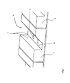
- the recordings are designed prismatic in cross-section, so as to easily achieve the correct positioning of the products in the recordings of the band members.
- the openings are arranged at the bottom of the receptacles, so moved by the vacuum provided by the suction bar, the products to the bottom of the recordings and kept sucking there.
- the arrangement is chosen such that the first conveyor is arranged above the upper run of the conveyor belt and the second conveyor below the lower run, so that the products of the first conveyor by utilizing gravity to the recordings of the band members pass and in these recordings, if necessary, by the acting on the openings of the upper Trumms squeegee are properly positioned by the mediated via the openings vacuum, while the transfer of the products from the bottom Trumm in the second conveyor in a simple manner happens that the connection to Low pressure source is terminated.
- first conveyor is oriented perpendicular and the second conveyor parallel to the conveyor belt and the lower run of the conveyor belt for parallel and rectified movement with the second conveyor is provided.
- This arrangement substantially ensures good accessibility to the conveyor belt, which initially transports the products from the first conveyor to the latter, thus allowing control of the products, while orientation of the lower run relative to the second conveyor facilitates proper transfer, especially if the second conveyor transports a molding film with wells, in which the products are to be stored selectively, so that a synchronization between the conveyor belt and the second conveyor is required.
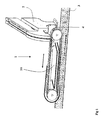
- the device 1 comprises an endlessly circulating conveyor belt 4, which is formed from individual belt members 5, each having a receptacle 6 for the products, in the receiving surfaces 7, in the embodiment shown namely in the bottom 8 of the receptacle 6, 9 open, which are connected to a arranged between the upper Trumm and the lower run of the conveyor belt 4 suction strip 10.
- the receptacles 6 are in cross section designed prismatic and thus cause a correct positioning of the syringes, the first of the conveyor 2, for example, in the DE 10 2004 017 228 described type, are passed to the conveyor belt 4.
- the first conveyor 2 is arranged above the upper run of the conveyor belt 4 in a vertical orientation, while the second conveyor 3 is oriented below the lower run parallel to the conveyor belt 4.
Abstract
Description
Die Erfindung betrifft eine Vorrichtung zum Übergeben von länglichen Produkten, wie Spritzen, Ampullen oder dergl., von einer ersten die Produkte in einer horizontalen Orientierung bereitstellenden Fördereinrichtung an eine zweite Fördereinrichtung.The invention relates to a device for transferring elongated products, such as syringes, ampoules or the like, from a first conveyor providing the products in a horizontal orientation to a second conveyor.
Eine derartige Vorrichtung ist in der nicht vorveröffentlichten deutschen Patentanmeldung
Der Erfindung liegt die Aufgabe zugrunde, eine Vorrichtung der eingangs genannten Art so auszubilden, dass bei verringertem apparativem Aufwand eine zuverlässige Arbeitsweise erzielt wird.The invention has the object of providing a device of the type mentioned in such a way that with reduced equipment expense a reliable operation is achieved.
Diese Aufgabe wird nach der Erfindung bei einer Vorrichtung der eingangs genannten Art dadurch gelöst, dass ein endlos umlaufendes Förderband vorgesehen ist, gebildet aus Bandgliedern, die eine Aufnahme für die Produkte aufweisen, in deren Aufnahmeflächen Öffnungen münden, die mit einer zwischen dem oberen Trumm und dem unteren Trumm des Förderbandes angeordneten, zumindest mit dem unteren Trumm zusammenwirkende Saugleiste verbunden sind.This object is achieved according to the invention in a device of the type mentioned in that an endlessly circulating conveyor belt is provided, formed from band members having a receptacle for the products, open in the receiving surfaces openings, with a between the upper Trumm and arranged at the bottom run of the conveyor belt, at least connected to the bottom Trumm co-operating suction strip.
Diese Vorrichtung zeichnet sich dadurch aus, dass das die von der ersten Fördereinrichtung herangeförderten Produkte aufnehmende Förderband zugleich auch für die Abgabe der Produkte an die zweite Fördereinrichtung zuständig ist und dadurch der Einsatz eines Pick-&-Place-Systemes vollständig vermieden werden kann, wobei diese Vermeidung auf eine konstruktiv sehr einfache Weise erreicht wird durch Verwenden der Vakuumtechnik für das Koppelglied zwischen der ersten Fördereinrichtung und der zweiten Fördereinrichtung.This device is distinguished by the fact that the conveyor belt receiving the products conveyed by the first conveyor device is at the same time also responsible for the delivery of the products to the second conveyor device, thereby completely avoiding the use of a pick-and-place system Avoidance is achieved in a structurally very simple manner by using the vacuum technique for the coupling member between the first conveyor and the second conveyor.
Dabei ist im Rahmen der Erfindung vorgesehen, dass die Aufnahmen im Querschnitt prismenartig gestaltet sind, um so auf einfache Weise die korrekte Positionierung der Produkte in den Aufnahmen der Bandglieder zu erzielen.It is provided in the context of the invention that the recordings are designed prismatic in cross-section, so as to easily achieve the correct positioning of the products in the recordings of the band members.
Dabei bietet es sich dann an, dass die Öffnungen am Boden der Aufnahmen angeordnet sind, also durch den von der Saugleiste bereit gestellten Unterdruck die Produkte zum Boden der Aufnahmen bewegt und dort saugend gehalten werden.It then makes sense that the openings are arranged at the bottom of the receptacles, so moved by the vacuum provided by the suction bar, the products to the bottom of the recordings and kept sucking there.
Aus Gründen der Einfachheit ist die Anordnung so gewählt, dass die erste Fördereinrichtung oberhalb des oberen Trumms des Förderbandes angeordnet ist und die zweite Fördereinrichtung unterhalb des unteren Trumms, so dass die Produkte von der ersten Fördereinrichtung unter Ausnutzung der Schwerkraft an die Aufnahmen der Bandglieder übergeben und in diesen Aufnahmen ggfs. durch die auch auf die Öffnungen des oberen Trumms wirkende Saugleiste durch den über die Öffnungen vermittelten Unterdruck richtig positioniert werden, während die Übergabe der Produkte aus dem unteren Trumm in die zweite Fördereinrichtung in einfacher Weise dadurch geschieht, dass die Verbindung zur Unterdruckquelle beendet wird.For reasons of simplicity, the arrangement is chosen such that the first conveyor is arranged above the upper run of the conveyor belt and the second conveyor below the lower run, so that the products of the first conveyor by utilizing gravity to the recordings of the band members pass and in these recordings, if necessary, by the acting on the openings of the upper Trumms squeegee are properly positioned by the mediated via the openings vacuum, while the transfer of the products from the bottom Trumm in the second conveyor in a simple manner happens that the connection to Low pressure source is terminated.
Als zweckmäßig hat es sich erwiesen, dass die erste Fördereinrichtung senkrecht und die zweite Fördereinrichtung parallel zu dem Förderband orientiert und das untere Trumm des Förderbandes zur parallelen und gleichgerichteten Bewegung mit der zweiten Fördereinrichtung vorgesehen ist. Durch diese Anordnung ist im wesentlichen eine gute Zugänglichkeit zu dem Förderband gewährleistet, das die Produkte von der ersten Fördereinrichtung zunächst zu dieser seitlich transportiert und so eine Kontrolle der Produkte ermöglicht, während die Orientierung des unteren Trumms relativ zu der zweiten Fördereinrichtung die ordnungsgemäße Übergabe erleichtert, inbesondere wenn die zweite Fördereinrichtung eine Formfolie mit Näpfen transportiert, in die gezielt die Produkte abgelegt werden sollen, so dass eine Synchronisierung zwischen dem Förderband und der zweiten Fördereinrichtung erforderlich ist.It has proven to be advantageous that the first conveyor is oriented perpendicular and the second conveyor parallel to the conveyor belt and the lower run of the conveyor belt for parallel and rectified movement with the second conveyor is provided. This arrangement substantially ensures good accessibility to the conveyor belt, which initially transports the products from the first conveyor to the latter, thus allowing control of the products, while orientation of the lower run relative to the second conveyor facilitates proper transfer, especially if the second conveyor transports a molding film with wells, in which the products are to be stored selectively, so that a synchronization between the conveyor belt and the second conveyor is required.
Im folgenden wird die Erfindung an einem in der Zeichnung dargestellten Ausführungsbeispiel näher erläutert; es zeigen:
- Fig. 1
- eine schematische perspektivische Darstellung der als Kopplungsglied zwischen der ersten Fördereinrichtung und der zweiten Fördereinrichtung fungierenden erfindungsgemäßen Vorrichtung, und
- Fig. 2
- eine Detaildarstellung der prismenartigen Aufnahme in dem Bandglied des Förderbandes.
- Fig. 1
- a schematic perspective view of acting as a coupling member between the first conveyor and the second conveyor device according to the invention, and
- Fig. 2
- a detailed representation of the prismatic recording in the band member of the conveyor belt.
In der Zeichnung ist eine Vorrichtung 1 gezeigt, die dazu dient, längliche Produkte, wie beispielsweise Spritzen, von einer ersten Fördereinrichtung 2 an eine zweite Fördereinrichtung 3 zu übergeben, wobei die Spritzen von der ersten Fördereinrichtung 2 in einer horizontalen Orientierung bereitgestellt werden. Die Vorrichtung 1 umfasst ein endlos umlaufendes Förderband 4, dass aus einzelnen Bandgliedern 5 gebildet ist, die jeweils eine Aufnahme 6 für die Produkte aufweisen, in deren Aufnahmeflächen 7, in dem gezeigten Ausführungsbeispiel nämlich in dem Boden 8 der Aufnahme 6, Öffnungen 9 münden, die mit einer zwischen dem oberen Trumm und dem unteren Trumm des Förderbandes 4 angeordneten Saugleiste 10 verbunden sind. Die Aufnahmen 6 sind im Querschnitt prismenartig gestaltet und bewirken so eine korrekte Positionierung der Spritzen, die von der ersten Fördereinrichtung 2, beispielsweise der in der
Claims (5)
Aufnahmeflächen (7) Öffnungen (9) münden, die mit einer zwischen dem oberen Trumm und dem unteren Trumm des Förderbandes (4) angeordneten, zumindest mit dem unteren Trumm zusammenwirkenden Saugleiste (10) verbunden sind.Device for transferring elongated products, such as syringes, ampoules or the like, from a first conveyor (2) providing the products in a horizontal orientation to a second conveyor (3), characterized in that an endlessly circulating conveyor belt (4) is provided formed by band members (5) having a receptacle (6) for the products in which
Receiving surfaces (7) openings (9) open, which are connected to a between the upper run and the lower run of the conveyor belt (4) arranged, at least cooperating with the lower run suction strip (10).
Applications Claiming Priority (1)
| Application Number | Priority Date | Filing Date | Title |
|---|---|---|---|
| DE200510047268 DE102005047268B4 (en) | 2005-10-01 | 2005-10-01 | Device for transferring syringes, ampoules or the like |
Publications (2)
| Publication Number | Publication Date |
|---|---|
| EP1770029A2 true EP1770029A2 (en) | 2007-04-04 |
| EP1770029A3 EP1770029A3 (en) | 2008-05-14 |
Family
ID=37670695
Family Applications (1)
| Application Number | Title | Priority Date | Filing Date |
|---|---|---|---|
| EP06011329A Withdrawn EP1770029A3 (en) | 2005-10-01 | 2006-06-01 | Device for the transfer of elongated products |
Country Status (2)
| Country | Link |
|---|---|
| EP (1) | EP1770029A3 (en) |
| DE (1) | DE102005047268B4 (en) |
Cited By (4)
| Publication number | Priority date | Publication date | Assignee | Title |
|---|---|---|---|---|
| US20140135194A1 (en) * | 2011-03-17 | 2014-05-15 | Fameccanica.Data S.P.A. | Process and equipment for folding a pant type diaper |
| EP2962945A1 (en) * | 2014-07-02 | 2016-01-06 | Texa AG | Device for the gap-free transfer of unfilled tubes to a conveyor belt |
| CN117775666A (en) * | 2024-02-28 | 2024-03-29 | 济南巨能液压机电工程有限公司 | Hydraulic press shaping unloader |
| CN117775666B (en) * | 2024-02-28 | 2024-04-19 | 济南巨能液压机电工程有限公司 | Hydraulic press shaping unloader |
Citations (1)
| Publication number | Priority date | Publication date | Assignee | Title |
|---|---|---|---|---|
| CH582088A5 (en) | 1975-07-18 | 1976-11-30 | Fassbind Karl | Packing machine for cotton wool buds on sticks - has toothed belt gripping items by suction and vertically reciprocating ejector |
Family Cites Families (9)
| Publication number | Priority date | Publication date | Assignee | Title |
|---|---|---|---|---|
| DE1586102A1 (en) * | 1967-07-20 | 1970-04-02 | Hauni Werke Koerber & Co Kg | Method and device for forming cigarette blocks |
| FR2145433B1 (en) * | 1971-07-15 | 1975-02-21 | Tensor Corp | |
| DE2200947A1 (en) * | 1972-01-10 | 1973-07-19 | Heinrich Betz Kg Lissberg Masc | DEVICE FOR INSERTING AMPOULES OR DGL. OBJECTIVES |
| DE8135398U1 (en) * | 1981-12-04 | 1983-05-19 | Sortimat Creuz & Co Gmbh, 7057 Winnenden | DELIVERY DEVICE FOR INDIVIDUALLY FEED WORKPIECES |
| DE3938296A1 (en) * | 1989-11-17 | 1991-05-23 | Waldinger Maschinenbau Gmbh | METHOD AND DEVICE FOR PACKING LONG-EXTENDED PACKS LIKE MEDICINE AMPOULES IN PACKING CASES |
| IT1237907B (en) * | 1989-12-14 | 1993-06-18 | Italfarmaco Spa | ORIENTATION DEVICE AND LOADER OF AMPOULTS IN GENERAL, AND OF AMPOULES-SYRINGE IN PARTICULAR |
| DE10026331B4 (en) * | 2000-05-26 | 2005-09-01 | Robert Bosch Gmbh | Device for feeding products |
| ITBO20010594A1 (en) * | 2001-09-27 | 2003-03-27 | Ima Spa | UNIT FOR FEEDING PRODUCTS TO A BLISTERING MACHINE |
| DE102004017228A1 (en) * | 2004-04-05 | 2005-11-10 | Uhlmann Pac-Systeme Gmbh & Co Kg | Device for transferring upright syringes into packaging material |
-
2005
- 2005-10-01 DE DE200510047268 patent/DE102005047268B4/en not_active Expired - Fee Related
-
2006
- 2006-06-01 EP EP06011329A patent/EP1770029A3/en not_active Withdrawn
Patent Citations (1)
| Publication number | Priority date | Publication date | Assignee | Title |
|---|---|---|---|---|
| CH582088A5 (en) | 1975-07-18 | 1976-11-30 | Fassbind Karl | Packing machine for cotton wool buds on sticks - has toothed belt gripping items by suction and vertically reciprocating ejector |
Cited By (5)
| Publication number | Priority date | Publication date | Assignee | Title |
|---|---|---|---|---|
| US20140135194A1 (en) * | 2011-03-17 | 2014-05-15 | Fameccanica.Data S.P.A. | Process and equipment for folding a pant type diaper |
| EP2962945A1 (en) * | 2014-07-02 | 2016-01-06 | Texa AG | Device for the gap-free transfer of unfilled tubes to a conveyor belt |
| CH709841A1 (en) * | 2014-07-02 | 2016-01-15 | Texa Ag | Transfer device for transferring elongate, at least approximately hollow-cylindrical product units on a conveyor belt to supply a packing unit. |
| CN117775666A (en) * | 2024-02-28 | 2024-03-29 | 济南巨能液压机电工程有限公司 | Hydraulic press shaping unloader |
| CN117775666B (en) * | 2024-02-28 | 2024-04-19 | 济南巨能液压机电工程有限公司 | Hydraulic press shaping unloader |
Also Published As
| Publication number | Publication date |
|---|---|
| DE102005047268A1 (en) | 2007-04-12 |
| EP1770029A3 (en) | 2008-05-14 |
| DE102005047268B4 (en) | 2008-03-27 |
Similar Documents
| Publication | Publication Date | Title |
|---|---|---|
| DE102011051830A1 (en) | Transfer-conveyor for diverting transporting goods, like containers from one conveyor path to another conveyor path, has recesses that are arranged in cover plate form guide elements which form interacting guide assembly | |
| EP0222105A1 (en) | Method and device for putting compact-discs (CD) in CD boxes | |
| DE202016107412U1 (en) | Guide for chain of a general cargo conveyor | |
| EP0885821A1 (en) | Apparatus for aligning products having an approximately rectangular cross-section | |
| EP2070648A2 (en) | Transport belt module | |
| EP0163849B1 (en) | Transferring device for an automatically operating cable confection device | |
| EP0965413B1 (en) | Installation for carrying out a series of assembly and/or working operations on workpieces, in particular on small components | |
| EP1037829A1 (en) | Device for transferring two-dimensional products onto a transportation device | |
| EP1770029A2 (en) | Device for the transfer of elongated products | |
| DE3411452C2 (en) | Conveying device for workpiece carriers, in particular for an assembly machine | |
| DE102008018491B3 (en) | Method and device for implanting a chip module in a chip card body | |
| DE102016225587A1 (en) | Method for aligning a workpiece and alignment device | |
| EP0890398A1 (en) | Method and apparatus for producing multiple-part electrical contacts or switching elements | |
| DE102016208964A1 (en) | Cutting device and method for trimming semi-finished fiber products, Absammelvorrichtung for receiving fiber waste material and depositing system for storing semi-finished fiber | |
| WO2011063988A1 (en) | Separation device | |
| EP2242622B1 (en) | Method and device for connecting moulded pieces | |
| DE102014113720A1 (en) | Device for lateral guidance of containers and associated container treatment machine | |
| DE102014113738A1 (en) | DEVICE FOR COMBINING PORTIONS | |
| EP1536456B1 (en) | Support structure | |
| DE102018101141A1 (en) | Mounting system, mounting method with mounting unit | |
| DE102018204044A1 (en) | Thermoforming packaging machine with film deflection | |
| EP0573390B1 (en) | Insertion machine | |
| DE202010014141U1 (en) | Conveying device for plate-shaped workpieces | |
| CH699992A2 (en) | Förderband module. | |
| DE10202641B4 (en) | Delivery and acceptance device for data carrier cards |
Legal Events
| Date | Code | Title | Description |
|---|---|---|---|
| PUAI | Public reference made under article 153(3) epc to a published international application that has entered the european phase |
Free format text: ORIGINAL CODE: 0009012 |
|
| AK | Designated contracting states |
Kind code of ref document: A2 Designated state(s): AT BE BG CH CY CZ DE DK EE ES FI FR GB GR HU IE IS IT LI LT LU LV MC NL PL PT RO SE SI SK TR |
|
| AX | Request for extension of the european patent |
Extension state: AL BA HR MK YU |
|
| PUAL | Search report despatched |
Free format text: ORIGINAL CODE: 0009013 |
|
| AK | Designated contracting states |
Kind code of ref document: A3 Designated state(s): AT BE BG CH CY CZ DE DK EE ES FI FR GB GR HU IE IS IT LI LT LU LV MC NL PL PT RO SE SI SK TR |
|
| AX | Request for extension of the european patent |
Extension state: AL BA HR MK YU |
|
| 17P | Request for examination filed |
Effective date: 20080514 |
|
| 17Q | First examination report despatched |
Effective date: 20080703 |
|
| AKX | Designation fees paid |
Designated state(s): AT BE BG CH CY CZ DE DK EE ES FI FR GB GR HU IE IS IT LI LT LU LV MC NL PL PT RO SE SI SK TR |
|
| STAA | Information on the status of an ep patent application or granted ep patent |
Free format text: STATUS: THE APPLICATION HAS BEEN WITHDRAWN |
|
| 18W | Application withdrawn |
Effective date: 20090522 |