EP1768357A2 - Mobile communication terminal - Google Patents
Mobile communication terminal Download PDFInfo
- Publication number
- EP1768357A2 EP1768357A2 EP06020154A EP06020154A EP1768357A2 EP 1768357 A2 EP1768357 A2 EP 1768357A2 EP 06020154 A EP06020154 A EP 06020154A EP 06020154 A EP06020154 A EP 06020154A EP 1768357 A2 EP1768357 A2 EP 1768357A2
- Authority
- EP
- European Patent Office
- Prior art keywords
- guide part
- terminal
- weight pendulum
- opened
- pendulum
- Prior art date
- Legal status (The legal status is an assumption and is not a legal conclusion. Google has not performed a legal analysis and makes no representation as to the accuracy of the status listed.)
- Granted
Links
Images


Classifications
-
- H—ELECTRICITY
- H04—ELECTRIC COMMUNICATION TECHNIQUE
- H04B—TRANSMISSION
- H04B1/00—Details of transmission systems, not covered by a single one of groups H04B3/00 - H04B13/00; Details of transmission systems not characterised by the medium used for transmission
- H04B1/38—Transceivers, i.e. devices in which transmitter and receiver form a structural unit and in which at least one part is used for functions of transmitting and receiving
-
- H—ELECTRICITY
- H04—ELECTRIC COMMUNICATION TECHNIQUE
- H04M—TELEPHONIC COMMUNICATION
- H04M1/00—Substation equipment, e.g. for use by subscribers
- H04M1/02—Constructional features of telephone sets
- H04M1/0202—Portable telephone sets, e.g. cordless phones, mobile phones or bar type handsets
- H04M1/0206—Portable telephones comprising a plurality of mechanically joined movable body parts, e.g. hinged housings
- H04M1/0208—Portable telephones comprising a plurality of mechanically joined movable body parts, e.g. hinged housings characterized by the relative motions of the body parts
- H04M1/0235—Slidable or telescopic telephones, i.e. with a relative translation movement of the body parts; Telephones using a combination of translation and other relative motions of the body parts
- H04M1/0237—Sliding mechanism with one degree of freedom
-
- H—ELECTRICITY
- H04—ELECTRIC COMMUNICATION TECHNIQUE
- H04M—TELEPHONIC COMMUNICATION
- H04M1/00—Substation equipment, e.g. for use by subscribers
- H04M1/02—Constructional features of telephone sets
- H04M1/0202—Portable telephone sets, e.g. cordless phones, mobile phones or bar type handsets
- H04M1/0206—Portable telephones comprising a plurality of mechanically joined movable body parts, e.g. hinged housings
- H04M1/0208—Portable telephones comprising a plurality of mechanically joined movable body parts, e.g. hinged housings characterized by the relative motions of the body parts
- H04M1/0225—Rotatable telephones, i.e. the body parts pivoting to an open position around an axis perpendicular to the plane they define in closed position
- H04M1/0233—Including a rotatable display body part
Definitions
- the present invention relates to a mobile communication terminal and, more particularly, to a mobile communication terminal having an opening/closing auxiliary device that easily opens or closes the terminal.
- a mobile communication terminal such as a mobile phone or a PDA, is a mobile electronic device that allows a user to wirelessly transmit, receive, read or process information while traveling.
- the development of information communication technologies and memory technologies allows mobile communication terminals to provide extended functions such as capturing still or moving images, reproducing or editing various multimedia files and providing TV broadcasting to users.
- Mobile communication terminals are becoming light and slim so as to be easily carried by a user. Therefore, they need to be mechanically supported in implementing diverse functions within a device of small and limited size.
- FIGS. 1 and 2 illustrate an example of a related art mobile communication terminal 1.
- the related art mobile communication terminal 1 includes a first body 10 and a second body 20 connected to the first body such that the second body can be slidably opened and closed with respect to the first body.
- a first keypad 11 having a plurality of key buttons is installed at a front surface of the first body 10 to allow a user to input information or issue a control command.
- a slide module 30 is installed between the first 10 body and second 20 body to guide the second body as it is slidably opened and closed with respect to the first body.
- the slide module 30 includes a first slide member 31 fixed on the first body 10, a second slide member 32 fixed on the second body 20 and an elastic connection member 33 connecting the first and second slide members and providing elastic force when the second slide member moves with respect to the first slide member. Accordingly, as illustrated in FIG. 2, when a user applies force to the second body 20, the second body continues to slide in a direction that it has been moved according to an operation of the elastic connection member 33 and is opened with respect to the first body 10.
- the user When opening and closing the related at mobile communication terminal 1, the user must use his or her other hand or the fingers on the hand in which the terminal is held in order to open the second body 20. If the user cannot use his or her other hand, for example, when the other hand is busy or if the user's finger is handicapped, the user is unable to easily open and close the terminal.
- One object of the present invention is to provide a mobile communication terminal having two connected bodies which are opened and closed that allow a user to open or close the mobile communication terminal without using a finger directly.
- a mobile communication terminal in one aspect of the present invention, includes a first body, a second body connected with the first body such that it can be slidably moved with respect to the first body by a slide module and a weight pendulum adapted to be movable by a guide part formed at the second body such that the terminal may be opened or closed by applying force in a direction that the second body is in an opened or closed position with respect to the first body, the force applied by physically moving the terminal.
- the guide part is formed in a lengthwise direction on the second body and includes a step for preventing the weight pendulum from being released. It is further contemplated that the terminal further includes a stopper unit adapted to stop the weight pendulum such that the weight pendulum is maintained at its stopped position.
- the stopper unit includes a first magnet installed at a first end of the guide part and adapted to attach the weight pendulum by magnetic force when the second body is in the opened position and a second magnet installed at a second end of the guide part and adapted to attach the weight pendulum by magnetic force when the second body is in the closed position.
- the stopper unit includes a first stopper protrusion formed at a first end of the guide part and adapted to fix the weight pendulum when the second body is in the opened position, a second stopper protrusion formed at a second end of the guide part and adapted to fix the weight pendulum when the second body is in the closed position and a stopping recess formed on the weight pendulum and adapted to engage the first stopper protrusion when the first body is in the opened position and engage the second stopper protrusion when the second body is in the closed position.
- the first stopper protrusion and the second stopper protrusion are formed such that they protrude at the side of the guide part. It is further contemplated that the terminal further includes a first buffer formed at a first end of the guide part and a second buffer formed at a first end of the guide part such that an impact of the weight pendulum with the first end and the second end of the guide part is reduced.
- the first buffer and second buffer are made of rubber or silicon.
- a mobile communication terminal in another aspect of the present invention, includes a first body, a second body connected to the first body such that it can be swingably moved with respect to the first body by a hinge module and a weight pendulum adapted to be movable by a guide part formed at the second body such that the terminal may be opened or closed by applying force in a direction that the second body is in an opened or closed position with respect to the first body, the force applied by physically moving the terminal.
- the guide part is formed in a circular arc with a certain length on the second body and further including a step formed at the side of the guide part to prevent the weight pendulum from being released from the guide part. It is further contemplated that the terminal further includes a stopper unit adapted to stop the weight pendulum such that the weight pendulum is maintained at its stopped position.
- the stopper unit includes a first magnet installed at a first end of the guide part and adapted to attach the weight pendulum by magnetic force when the second body is in the opened position and a second magnet installed at a second end of the guide part and adapted to attach the weight pendulum by magnetic force when the second body is in the closed position.
- the stopper unit includes a first stopper protrusion formed at a first end of the guide part and adapted to fix the weight pendulum when the second body is in the opened position, a second stopper protrusion formed at a second end of the guide part and adapted to fix the weight pendulum when the second body is in the closed position and a stopping recess formed on the weight pendulum and adapted to engage the first stopper protrusion when the first body is in the opened position and engage the second stopper protrusion when the second body is in the closed position.
- first stopper protrusion and the second stopper protrusion are formed such that they protrude at the side of the guide part. It is further contemplated that the first stopper protrusion and the second stopper protrusion are supported such that they can be elastically protruded or retracted.
- the terminal further includes a first buffer formed at a first end of the guide part and a second buffer formed at a first end of the guide part such that an impact of the weight pendulum with the first end and the second end of the guide part is reduced. It is further contemplated that the first buffer and second buffer are made of rubber or silicon.
- a first end of the weight pendulum is pivoted and rotatably connected with the hinge module. It is further contemplated that a second end of the weight pendulum fixes is fixed to the guide part and the first end of the weight pendulum is connected to a pivot connection member pivoted at the hinge module.
- a mobile communication terminal in another aspect of the present invention, includes a first body, a second body connected with the first body such that it can be moved with respect to the first body and a weight pendulum adapted to be movable by a guide part formed at the second body such that the terminal may be opened or closed by applying force in a direction that the second body is in an opened or closed position with respect to the first body, the force applied by physically moving the terminal.
- FIG. 1 illustrates a side view of a mobile communication terminal according to the related art.
- FIG. 2 illustrates a side view showing an opened state of the mobile communication terminal in FIG. 1.
- FIG. 3 illustrates a perspective view of a mobile communication terminal according to a first embodiment of the present invention.
- FIG. 4 illustrates a separated perspective view showing the second body separated from the first body of the mobile communication terminal in FIG. 3.
- FIG. 5 is a partial side sectional view of the mobile communication terminal in FIG. 3.
- FIGS. 6 and 7 illustrate operational states of the mobile communication terminal in FIG. 3.
- FIG. 8 illustrates a rear view showing a partial section of the second body of a second embodiment of the present invention.
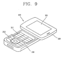
- FIG. 9 illustrates a perspective view of a mobile communication terminal according to a third embodiment of the present invention.
- FIG. 10 illustrates a separated perspective view showing the second body separated from the first body of the mobile communication terminal in FIG. 9.
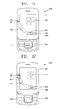
- FIG. 11 illustrates a plan view of the mobile communication terminal in FIG. 9.
- FIGS. 12 and 13 illustrate operational states of the mobile communication terminal in FIG. 9.
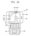
- FIG. 14 illustrates a plan view of a mobile communication terminal according to a fourth embodiment of the present invention.
- FIGS. 15 and 16 illustrate operational states of the mobile communication terminal in FIG. 14.
- FIG. 3 is a perspective view of a mobile communication terminal according to a first embodiment of the present invention.
- the mobile communication terminal 100 includes a first body 110 and a second body 120 that is slidably moved in order to open and close the terminal.
- first keypad 111 On a front surface of the first body 110, there is a first keypad 111 having a plurality of key buttons to input information or issue a control command and a microphone 112 for receiving a voice signal.
- a second keypad 122 is provided on a front surface of the second body 120.
- On a rear surface of the first body 110 there is a battery 113 installed for supplying power to the mobile communication terminal 100.
- a display 121 for displaying visual information and a speaker 123 for outputting a voice signal are installed on a front surface of the second body 120.
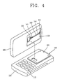
- FIG. 4 illustrates a separated perspective view showing the second body 120 separated from the first body 110 of the mobile communication terminal 100 in FIG. 3.
- a slide module 130 is installed between the first body 110 and second body 120 to allow the second body to slidably move to open and close in a lengthwise direction with respect to the first body.
- a weight pendulum 141 is installed to be linearly movable at the second body 120 so that when the terminal 100 is shaken in the lengthwise direction, the weight pendulum applies a force such that the second body is opened or closed.
- a guide part 143 is formed in a lengthwise direction at the second body 120 to allow the weight pendulum 141 to move linearly.
- the guide part 143 has a step 144 at the side to prevent the weight pendulum 141 from being released.
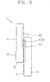
- FIG. 5 illustrated a partial side sectional view of the mobile communication terminal 100 in FIG. 3.
- the slide module 130 includes a slide member 131 fixed at the first body 110, a second slide member 132 fixed at the second body 120 and an elastic connection member 133 connecting the first slide member to the second slide member and providing elastic force when the second slide member is moved with respect to the first slide member.
- a stopper unit for stopping the weight pendulum 141 is provided at both the upper and lower ends of the guide part 143 so that the weight pendulum 141 can be maintained in a moved position.
- the stopper unit includes a first magnet 151 installed at an upper end of the guide part 143 to attach the weight pendulum by its magnetic force when the second body 120 is in an opened state and a second magnet 152 installed at a lower end of the guide part 143 to attach the weight pendulum by its magnetic force when the second body is in a closed state.
- the magnetic force of the first magnet 151 and second magnet 152 is strong enough to allow the weight pendulum 141 to move when the terminal 100 is shaken to open and close the second body 120.
- first and second buffer members 161 and 162 are installed at the upper and lower ends of the guide part 143, respectively.
- the buffer members 161 and 162 are made of rubber or silicon, and accordingly, noise caused by the impact with the weight pendulum 141 can be reduced.
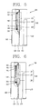
- FIGS. 6 and 7 illustrate operational states of the mobile communication terminal 100 in FIG. 5.
- the weight pendulum 141 is at the lower end of the guide part.
- the weight pendulum 141 at the lower end of the guide part 143 moves upward in the guide part as illustrated in FIG. 6.
- the second body 120 moves to the open position due to inertia as illustrated in FIG. 7.
- the upwardly moving weight pendulum 141 is stopped by the buffer member 161 when it reaches the upper end of the guide part 143 and the impact is transferred to the second body 120. Then, the second body 120 is moved upward due to the impact of the weight pendulum 141 and opened with respect to the first body 110 according to an operation of the slide module 130. The weight pendulum 141 is maintained at the position of the upper end of the guide part 143 according to the magnetic force of the first magnet 151.
- the buffer member 162 stops it and the corresponding impact is transferred to the second body 120. Then, the second body 120 is moved downward due to the impact of the weight pendulum 141 and the second body 120 is closed with respect to the first body 110 according to the operation of the slide module 130. The weight pendulum 141 is maintained at the upper end of the guide part 143 according to the magnetic force of the second magnet 152.
- the second body 120 can be opened or closed with respect to the first body 110 by simply shaking the mobile communication terminal 100.
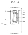
- FIG. 8 illustrates a rear view showing a partial section of the second body 220 according to a second embodiment of the present invention.
- a stopper unit can maintain a weight pendulum 241 at a position at an upper end or a lower end of a guide part 243.
- the stopper unit includes a first stopper protrusion 271 formed at the upper end of the guide part 243 that fixes the weight pendulum 241 when the second body 220 is in an opened state, a second stopper protrusion 272 formed at the lower end of the guide part 243 that fixes the weight pendulum when the second body is in a closed state and a stopping recess 273 formed the weight pendulum that allows the first and second stopper protrusions to be engaged.
- the first stopper protrusion 271 and second stopper protrusion 272 are protrusively formed at the side of the guide part 243 and the stopping recess 273 is also formed at the corresponding side of the weight pendulum 241.
- the first stopped protrusion 271 and second stopper protrusion 272 are supported by the guide part 243 such that they can be protruded or retreated elastically with respect to the guide part 243. Accordingly, when the weight pendulum 241 moves to the upper end of the guide part 243, the stopping recess 273 is engaged by the first stopper protrusion 271 such that it is maintained in a position at the upper end of the guide part. Conversely, when the weight pendulum 241 moves to the lower end of the guide part 243, the stopping recess 273 is engaged by the second stopper protrusion 272 and maintained in a position at the lower end at the guide part.
- FIG. 9 illustrates a perspective view of a mobile communication terminal 300 according to a third embodiment of the present invention.
- the mobile communication terminal 300 includes a first body 310 and a second body 320 that is swingably connected with the first body.
- a first keypad 311 having a plurality of key buttons for inputting information or issuing a control command is installed on a front surface of the first body 310 at a region opened or closed by the second body 320.
- a second keypad 312 for inputting information or issuing a control command without having to open the second body 320 is installed at one side of the first keypad.
- a display 321 for displaying visual information is installed on a front surface of the second body 320 and rotated together with the second body 320 as the second body is rotated.
- FIG. 10 illustrates a separated perspective view showing the second body 320 of the mobile communication terminal in FIG. 9 separated from the first body 310.
- a hinge module 330 is installed between the first body 310 and second body 320 in order to swingably connect the second body to the first body.
- a weight pendulum 341 is rotatably installed on a rear surface of the second body 320.
- the weight pendulum 341 applies force in a direction that the second body 320 is opened, and when the terminal 300 is shaken in a lengthwise direction, the weight pendulum 341 applies force in a direction that the second body is closed.
- a guide part 343 is formed in a circular arc on the rear surface of the second body 320 along which the weight pendulum 341 can be rotated to apply force to the second body.
- the guide part 323 includes a step 344 formed at the side to prevent the weight pendulum 341 from being released.
- a stopper unit is installed at both ends of the guide part 343 to stop the weight pendulum 341 so that the weight pendulum can be maintained at a moved position.
- the stopper unit includes a first magnet 351 installed at one end of the guide part 343 to attach the weight pendulum by its magnetic force when the second body 320 is in an opened state, and a second magnet 352 installed at an opposite end of the guide part 343 to attach the weight pendulum 341 by its magnetic force when the second body is in a closed state.
- First and second buffer members 361 and 362 are installed at the opposite ends, respectively, of the guide part 343 to lessen an impact when the weight pendulum 341 is stopped after being moved along the guide part 323 along the circular arc.
- FIGS. 11 to 13 illustrate operational states of the mobile communication terminal in FIG. 9.
- the mobile communication terminal 300 is in a closed state.
- the weight pendulum 341 positioned at the lower end of the guide part 343 moves along the guide part toward the upper end.
- the weight pendulum 141 contacts the first buffer member 361 as illustrated in FIG. 12, the second body 320 moves to the open position due to the inertia as illustrated in FIG. 13.
- the weight pendulum 341 that has moved upward after being rotated is stopped when it reaches the first buffer member 361 at the upper end of the guide part 343, and the corresponding impact is transferred to the second body 320. Accordingly, the second body 320 is rotated due to the impact of the weight pendulum 341 and then opened with respect to the first body 310 according to an operation of the hinge module 330.
- the weight pendulum 341 is maintained at the position of the upper end of the guide part 343 by a magnetic force of the first magnet 351.
- the downwardly moving weigh pendulum 341 is stopped when it reaches second buffer member 362 at the lower end of the guide part 343, and the corresponding impact is transferred to the second body 320. Accordingly, the second body 320 is rotated rightward due to the impact of the weight pendulum 341 and the second body is closed with respect to the first body 310 according to the operation of the hinge module 330.
- the weight pendulum 341 is maintained at the position at the lower end of the guide part 343 by a magnetic force of the second magnet 352.
- the second body 320 can be opened or closed with respect to the first body 310 by simply shaking the mobile communication terminal 300.
- FIG. 14 illustrates a plan view of a mobile communication terminal 400 according to a fourth embodiment of the present invention.
- the mobile communication terminal 400 includes a first body 410 and a second body 420 that is swingably connected with the first body.
- a first keypad 411 (refer to FIG. 16) having a plurality of key buttons for inputting information or issuing a control command is installed on a front surface of the first body 410 at a region opened or closed by the second body 420.
- a second keypad 412 for inputting information or issuing a control command without having to open the second body 420 is installed at one side of the first keypad 411.
- a display 421 for displaying visual information is installed on a front surface of the second body 420 and rotated together with the second body as the second body 420 is rotated.
- a hinge module 430 is installed between the first body 410 and second body 420 in order to swingably connect the second body to the first body.
- a weight pendulum 441 is rotatably installed at a rear surface of the second body 420. When the terminal 400 is shaken in a widthwise direction, the weight pendulum 441 applies force in a direction that the second body 420 is opened, and when the terminal 400 is shaken in a lengthwise direction, the weight pendulum 441 applies force in a direction that the second body is closed.
- One end of the weight pendulum 441 is pivoted and rotatably connected the hinge module 430. Specifically, one end of the weight pendulum 441 fixes the weight pendulum to the hinge module 430 and the other end of the weight pendulum is connected to a pivot connection member 442 pivoted at the hinge module.
- a guide part 443 may be formed at a rear surface of the second body 420 to allow the weight pendulum 441 to be rotatably moved.
- FIGS. 15 and 16 illustrate operational states of the mobile communication terminal in FIG. 14.
- the weight pendulum 441 is at the lower end of the guide part 443.
- the weight pendulum 441 moves upward in the guide part 443.
- the weight pendulum 441 contacts a buffer member 461 at the upper end of the guide part 430, the second body 420 is rotated leftward due to the inertia as shown in FIG .15.
- the rotated weight pendulum 441 is stopped when it reaches the buffer member 461 at the upper end of the guide part 443, and the corresponding impact is transferred to the second body 420. Accordingly, the second body 420 is rotated due to the impact of the weight pendulum 441 and opened with respect to the first body 410 according to the operation of the hinge module 430.
- the weight pendulum 441 is maintained at the position at the upper end of the guide part 443 by a magnetic force of a magnet 451.
- the rotated weight pendulum 441 is stopped when it reaches the buffer member 462 at the lower end of the guide part 443, and the corresponding impact is transferred to the second body 420. Accordingly, the second body 420 is rotated rightward due to the impact of the weight pendulum 441 and closed with respect to the first body 410 according to the operation of the hinge module 430.
- the weight pendulum 441 is maintained at the position at the lower end of the guide part 443 by a magnetic force of a magnet 452.
- the second body 420 can be opened or closed with respect to the first body by simply shaking the mobile communication terminal 400.
- the mobile communication terminal according to the present invention has many advantages. For example, with the mobile communication terminal held, the second body can be opened or closed with respect to the first body by moving the weight pendulum by simply shaking the mobile communication terminal, so user convenience can be improved. Because the weight pendulum can be maintained in its moved state by the stopper, unintentional opening or closing of the mobile communication terminal can be prevented. Additionally, the weight pendulum is applicable regardless of whether the mobile communication terminal is a slide type or a swing type mobile communication terminal.
Abstract
Description
- The present invention relates to a mobile communication terminal and, more particularly, to a mobile communication terminal having an opening/closing auxiliary device that easily opens or closes the terminal.
- A mobile communication terminal, such as a mobile phone or a PDA, is a mobile electronic device that allows a user to wirelessly transmit, receive, read or process information while traveling. The development of information communication technologies and memory technologies allows mobile communication terminals to provide extended functions such as capturing still or moving images, reproducing or editing various multimedia files and providing TV broadcasting to users.
- Mobile communication terminals are becoming light and slim so as to be easily carried by a user. Therefore, they need to be mechanically supported in implementing diverse functions within a device of small and limited size.
- FIGS. 1 and 2 illustrate an example of a related art
mobile communication terminal 1. As illustrated in FIG. 1, the related artmobile communication terminal 1 includes afirst body 10 and asecond body 20 connected to the first body such that the second body can be slidably opened and closed with respect to the first body. - A
first keypad 11 having a plurality of key buttons is installed at a front surface of thefirst body 10 to allow a user to input information or issue a control command. On a front surface of thesecond body 20, there are formed adisplay 21 for displaying visual information and asecond keypad 22 having a plurality of key buttons to allow the user to input information or issue a control command when the terminal is closed - A
slide module 30 is installed between the first 10 body and second 20 body to guide the second body as it is slidably opened and closed with respect to the first body. Theslide module 30 includes afirst slide member 31 fixed on thefirst body 10, asecond slide member 32 fixed on thesecond body 20 and anelastic connection member 33 connecting the first and second slide members and providing elastic force when the second slide member moves with respect to the first slide member. Accordingly, as illustrated in FIG. 2, when a user applies force to thesecond body 20, the second body continues to slide in a direction that it has been moved according to an operation of theelastic connection member 33 and is opened with respect to thefirst body 10. - When opening and closing the related at
mobile communication terminal 1, the user must use his or her other hand or the fingers on the hand in which the terminal is held in order to open thesecond body 20. If the user cannot use his or her other hand, for example, when the other hand is busy or if the user's finger is handicapped, the user is unable to easily open and close the terminal. - One object of the present invention is to provide a mobile communication terminal having two connected bodies which are opened and closed that allow a user to open or close the mobile communication terminal without using a finger directly.
- In one aspect of the present invention, a mobile communication terminal is provided. The mobile terminal includes a first body, a second body connected with the first body such that it can be slidably moved with respect to the first body by a slide module and a weight pendulum adapted to be movable by a guide part formed at the second body such that the terminal may be opened or closed by applying force in a direction that the second body is in an opened or closed position with respect to the first body, the force applied by physically moving the terminal.
- It is contemplated that the guide part is formed in a lengthwise direction on the second body and includes a step for preventing the weight pendulum from being released. It is further contemplated that the terminal further includes a stopper unit adapted to stop the weight pendulum such that the weight pendulum is maintained at its stopped position.
- It is contemplated that the stopper unit includes a first magnet installed at a first end of the guide part and adapted to attach the weight pendulum by magnetic force when the second body is in the opened position and a second magnet installed at a second end of the guide part and adapted to attach the weight pendulum by magnetic force when the second body is in the closed position. It is further contemplated that the stopper unit includes a first stopper protrusion formed at a first end of the guide part and adapted to fix the weight pendulum when the second body is in the opened position, a second stopper protrusion formed at a second end of the guide part and adapted to fix the weight pendulum when the second body is in the closed position and a stopping recess formed on the weight pendulum and adapted to engage the first stopper protrusion when the first body is in the opened position and engage the second stopper protrusion when the second body is in the closed position.
- It is contemplated that the first stopper protrusion and the second stopper protrusion are formed such that they protrude at the side of the guide part. It is further contemplated that the terminal further includes a first buffer formed at a first end of the guide part and a second buffer formed at a first end of the guide part such that an impact of the weight pendulum with the first end and the second end of the guide part is reduced. Preferably, the first buffer and second buffer are made of rubber or silicon.
- In another aspect of the present invention, a mobile communication terminal is provided. The mobile terminal includes a first body, a second body connected to the first body such that it can be swingably moved with respect to the first body by a hinge module and a weight pendulum adapted to be movable by a guide part formed at the second body such that the terminal may be opened or closed by applying force in a direction that the second body is in an opened or closed position with respect to the first body, the force applied by physically moving the terminal.
- It is contemplated that the guide part is formed in a circular arc with a certain length on the second body and further including a step formed at the side of the guide part to prevent the weight pendulum from being released from the guide part. It is further contemplated that the terminal further includes a stopper unit adapted to stop the weight pendulum such that the weight pendulum is maintained at its stopped position.
- It is contemplated that the stopper unit includes a first magnet installed at a first end of the guide part and adapted to attach the weight pendulum by magnetic force when the second body is in the opened position and a second magnet installed at a second end of the guide part and adapted to attach the weight pendulum by magnetic force when the second body is in the closed position. It is further contemplated that the stopper unit includes a first stopper protrusion formed at a first end of the guide part and adapted to fix the weight pendulum when the second body is in the opened position, a second stopper protrusion formed at a second end of the guide part and adapted to fix the weight pendulum when the second body is in the closed position and a stopping recess formed on the weight pendulum and adapted to engage the first stopper protrusion when the first body is in the opened position and engage the second stopper protrusion when the second body is in the closed position.
- It is contemplated that the first stopper protrusion and the second stopper protrusion are formed such that they protrude at the side of the guide part. It is further contemplated that the first stopper protrusion and the second stopper protrusion are supported such that they can be elastically protruded or retracted.
- It is contemplated that the terminal further includes a first buffer formed at a first end of the guide part and a second buffer formed at a first end of the guide part such that an impact of the weight pendulum with the first end and the second end of the guide part is reduced. It is further contemplated that the first buffer and second buffer are made of rubber or silicon.
- It is contemplated that a first end of the weight pendulum is pivoted and rotatably connected with the hinge module. It is further contemplated that a second end of the weight pendulum fixes is fixed to the guide part and the first end of the weight pendulum is connected to a pivot connection member pivoted at the hinge module.
- In another aspect of the present invention, a mobile communication terminal is provided. The mobile terminal includes a first body, a second body connected with the first body such that it can be moved with respect to the first body and a weight pendulum adapted to be movable by a guide part formed at the second body such that the terminal may be opened or closed by applying force in a direction that the second body is in an opened or closed position with respect to the first body, the force applied by physically moving the terminal.
- Additional features and advantages of the invention will be set forth in the description which follows, and in part will be apparent from the description, or may be learned by practice of the invention. It is to be understood that both the foregoing general description and the following detailed description of the present invention are exemplary and explanatory and are intended to provide further explanation of the invention as claimed. These and other embodiments will also become readily apparent to those skilled in the art from the following detailed description of the embodiments having reference to the attached figures, the invention not being limited to any particular embodiments disclosed.
- The invention will be described in detail with reference to the following drawings in which like reference numerals refer to like elements wherein:
- FIG. 1 illustrates a side view of a mobile communication terminal according to the related art.
- FIG. 2 illustrates a side view showing an opened state of the mobile communication terminal in FIG. 1.
- FIG. 3 illustrates a perspective view of a mobile communication terminal according to a first embodiment of the present invention.
- FIG. 4 illustrates a separated perspective view showing the second body separated from the first body of the mobile communication terminal in FIG. 3.
- FIG. 5 is a partial side sectional view of the mobile communication terminal in FIG. 3.
- FIGS. 6 and 7 illustrate operational states of the mobile communication terminal in FIG. 3.
- FIG. 8 illustrates a rear view showing a partial section of the second body of a second embodiment of the present invention.
- FIG. 9 illustrates a perspective view of a mobile communication terminal according to a third embodiment of the present invention.
- FIG. 10 illustrates a separated perspective view showing the second body separated from the first body of the mobile communication terminal in FIG. 9.
- FIG. 11 illustrates a plan view of the mobile communication terminal in FIG. 9.
- FIGS. 12 and 13 illustrate operational states of the mobile communication terminal in FIG. 9.
- FIG. 14 illustrates a plan view of a mobile communication terminal according to a fourth embodiment of the present invention.
- FIGS. 15 and 16 illustrate operational states of the mobile communication terminal in FIG. 14.
- The exemplary embodiments of the present invention will now be described with reference to the accompanying drawings.
- FIG. 3 is a perspective view of a mobile communication terminal according to a first embodiment of the present invention. As illustrated in FIG. 3, the
mobile communication terminal 100 includes afirst body 110 and asecond body 120 that is slidably moved in order to open and close the terminal. - On a front surface of the
first body 110, there is afirst keypad 111 having a plurality of key buttons to input information or issue a control command and amicrophone 112 for receiving a voice signal. Asecond keypad 122 is provided on a front surface of thesecond body 120. On a rear surface of thefirst body 110, there is abattery 113 installed for supplying power to themobile communication terminal 100. Adisplay 121 for displaying visual information and aspeaker 123 for outputting a voice signal are installed on a front surface of thesecond body 120. With such a structure, a user can slidably move thesecond body 120 to open with respect to thefirst body 110 in order to enter a call mode or input/output information through the firstkey pad 112 andsecond keypad 122. - FIG. 4 illustrates a separated perspective view showing the
second body 120 separated from thefirst body 110 of themobile communication terminal 100 in FIG. 3. As illustrated in FIG. 4, aslide module 130 is installed between thefirst body 110 andsecond body 120 to allow the second body to slidably move to open and close in a lengthwise direction with respect to the first body. Aweight pendulum 141 is installed to be linearly movable at thesecond body 120 so that when the terminal 100 is shaken in the lengthwise direction, the weight pendulum applies a force such that the second body is opened or closed. - A
guide part 143 is formed in a lengthwise direction at thesecond body 120 to allow theweight pendulum 141 to move linearly. Theguide part 143 has astep 144 at the side to prevent theweight pendulum 141 from being released. - FIG. 5 illustrated a partial side sectional view of the
mobile communication terminal 100 in FIG. 3. As illustrates in FIG. 5, theslide module 130 includes aslide member 131 fixed at thefirst body 110, asecond slide member 132 fixed at thesecond body 120 and anelastic connection member 133 connecting the first slide member to the second slide member and providing elastic force when the second slide member is moved with respect to the first slide member. - A stopper unit for stopping the
weight pendulum 141 is provided at both the upper and lower ends of theguide part 143 so that theweight pendulum 141 can be maintained in a moved position. The stopper unit includes afirst magnet 151 installed at an upper end of theguide part 143 to attach the weight pendulum by its magnetic force when thesecond body 120 is in an opened state and asecond magnet 152 installed at a lower end of theguide part 143 to attach the weight pendulum by its magnetic force when the second body is in a closed state. - Preferably, the magnetic force of the
first magnet 151 andsecond magnet 152 is strong enough to allow theweight pendulum 141 to move when the terminal 100 is shaken to open and close thesecond body 120. In order to lessen an impact generated when theweight pendulum 141 moves up and down along theguide part 143 toward thefirst magnet 151 andsecond magnet 152, first andsecond buffer members guide part 143, respectively. Preferably, thebuffer members weight pendulum 141 can be reduced. - FIGS. 6 and 7 illustrate operational states of the
mobile communication terminal 100 in FIG. 5. In the state illustrated in FIG. 5, theweight pendulum 141 is at the lower end of the guide part. When themobile communication terminal 100 is shaken upward, theweight pendulum 141 at the lower end of theguide part 143 moves upward in the guide part as illustrated in FIG. 6. When theweight pendulum 141 contacts thebuffer member 161 at the upper and of theguide part 143, thesecond body 120 moves to the open position due to inertia as illustrated in FIG. 7. - The upwardly moving
weight pendulum 141 is stopped by thebuffer member 161 when it reaches the upper end of theguide part 143 and the impact is transferred to thesecond body 120. Then, thesecond body 120 is moved upward due to the impact of theweight pendulum 141 and opened with respect to thefirst body 110 according to an operation of theslide module 130. Theweight pendulum 141 is maintained at the position of the upper end of theguide part 143 according to the magnetic force of thefirst magnet 151. - Conversely, with the
second body 120 opened as illustrated in FIG. 7, when themobile communication terminal 100 is shaken downward, theweight pendulum 141 positioned at the upper end of theguide part 143 moves downward in the guide part. When the weight pendulum contacts thebuffer member 162 at the lower end of theguide part 143, thesecond body 120 moves to closed position due to the inertia. - When the downwardly moving
weight pendulum 141 reaches the lower end of theguide part 143, thebuffer member 162 stops it and the corresponding impact is transferred to thesecond body 120. Then, thesecond body 120 is moved downward due to the impact of theweight pendulum 141 and thesecond body 120 is closed with respect to thefirst body 110 according to the operation of theslide module 130. Theweight pendulum 141 is maintained at the upper end of theguide part 143 according to the magnetic force of thesecond magnet 152. - In this manner, the
second body 120 can be opened or closed with respect to thefirst body 110 by simply shaking themobile communication terminal 100. - FIG. 8 illustrates a rear view showing a partial section of the
second body 220 according to a second embodiment of the present invention. In the second embodiment of the present invention, a stopper unit can maintain aweight pendulum 241 at a position at an upper end or a lower end of aguide part 243. - As illustrated in FIG. 8, the stopper unit includes a
first stopper protrusion 271 formed at the upper end of theguide part 243 that fixes theweight pendulum 241 when thesecond body 220 is in an opened state, asecond stopper protrusion 272 formed at the lower end of theguide part 243 that fixes the weight pendulum when the second body is in a closed state and a stoppingrecess 273 formed the weight pendulum that allows the first and second stopper protrusions to be engaged. Thefirst stopper protrusion 271 andsecond stopper protrusion 272 are protrusively formed at the side of theguide part 243 and the stoppingrecess 273 is also formed at the corresponding side of theweight pendulum 241. - Preferably, the first stopped
protrusion 271 andsecond stopper protrusion 272 are supported by theguide part 243 such that they can be protruded or retreated elastically with respect to theguide part 243. Accordingly, when theweight pendulum 241 moves to the upper end of theguide part 243, the stoppingrecess 273 is engaged by thefirst stopper protrusion 271 such that it is maintained in a position at the upper end of the guide part. Conversely, when theweight pendulum 241 moves to the lower end of theguide part 243, the stoppingrecess 273 is engaged by thesecond stopper protrusion 272 and maintained in a position at the lower end at the guide part. - FIG. 9 illustrates a perspective view of a
mobile communication terminal 300 according to a third embodiment of the present invention. As illustrated in FIG. 9, themobile communication terminal 300 includes afirst body 310 and asecond body 320 that is swingably connected with the first body. - A
first keypad 311 having a plurality of key buttons for inputting information or issuing a control command is installed on a front surface of thefirst body 310 at a region opened or closed by thesecond body 320. Asecond keypad 312 for inputting information or issuing a control command without having to open thesecond body 320 is installed at one side of the first keypad. Adisplay 321 for displaying visual information is installed on a front surface of thesecond body 320 and rotated together with thesecond body 320 as the second body is rotated. - FIG. 10 illustrates a separated perspective view showing the
second body 320 of the mobile communication terminal in FIG. 9 separated from thefirst body 310. As illustrated in FIG. 10, ahinge module 330 is installed between thefirst body 310 andsecond body 320 in order to swingably connect the second body to the first body. - A
weight pendulum 341 is rotatably installed on a rear surface of thesecond body 320. When the terminal 300 is shaken in a widthwise direction, theweight pendulum 341 applies force in a direction that thesecond body 320 is opened, and when the terminal 300 is shaken in a lengthwise direction, theweight pendulum 341 applies force in a direction that the second body is closed. - A
guide part 343 is formed in a circular arc on the rear surface of thesecond body 320 along which theweight pendulum 341 can be rotated to apply force to the second body. The guide part 323 includes astep 344 formed at the side to prevent theweight pendulum 341 from being released. - A stopper unit is installed at both ends of the
guide part 343 to stop theweight pendulum 341 so that the weight pendulum can be maintained at a moved position. The stopper unit includes afirst magnet 351 installed at one end of theguide part 343 to attach the weight pendulum by its magnetic force when thesecond body 320 is in an opened state, and asecond magnet 352 installed at an opposite end of theguide part 343 to attach theweight pendulum 341 by its magnetic force when the second body is in a closed state. First andsecond buffer members guide part 343 to lessen an impact when theweight pendulum 341 is stopped after being moved along the guide part 323 along the circular arc. - FIGS. 11 to 13 illustrate operational states of the mobile communication terminal in FIG. 9. In the state illustrated in FIG. 11, the
mobile communication terminal 300 is in a closed state. When themobile communication terminal 300 is shaken leftward, theweight pendulum 341 positioned at the lower end of theguide part 343 moves along the guide part toward the upper end. When theweight pendulum 141 contacts thefirst buffer member 361 as illustrated in FIG. 12, thesecond body 320 moves to the open position due to the inertia as illustrated in FIG. 13. - The
weight pendulum 341 that has moved upward after being rotated is stopped when it reaches thefirst buffer member 361 at the upper end of theguide part 343, and the corresponding impact is transferred to thesecond body 320. Accordingly, thesecond body 320 is rotated due to the impact of theweight pendulum 341 and then opened with respect to thefirst body 310 according to an operation of thehinge module 330. Theweight pendulum 341 is maintained at the position of the upper end of theguide part 343 by a magnetic force of thefirst magnet 351. - Conversely, with the
second body 320 opened as illustrated in FIG. 13, when themobile communication terminal 300 is shaken up and down, theweight pendulum 341 positioned at the upper end of theguide part 343 moves downward in the guide part. When theweight pendulum 341 contacts thesecond buffer member 362 at the lower end of theguide part 343, thesecond body 320 moves to the closed position due to the inertia. - The downwardly moving
weigh pendulum 341 is stopped when it reachessecond buffer member 362 at the lower end of theguide part 343, and the corresponding impact is transferred to thesecond body 320. Accordingly, thesecond body 320 is rotated rightward due to the impact of theweight pendulum 341 and the second body is closed with respect to thefirst body 310 according to the operation of thehinge module 330. Theweight pendulum 341 is maintained at the position at the lower end of theguide part 343 by a magnetic force of thesecond magnet 352. - In this manner, the
second body 320 can be opened or closed with respect to thefirst body 310 by simply shaking themobile communication terminal 300. - FIG. 14 illustrates a plan view of a
mobile communication terminal 400 according to a fourth embodiment of the present invention. As illustrated in FIG. 14, themobile communication terminal 400 includes afirst body 410 and asecond body 420 that is swingably connected with the first body. - A first keypad 411 (refer to FIG. 16) having a plurality of key buttons for inputting information or issuing a control command is installed on a front surface of the
first body 410 at a region opened or closed by thesecond body 420. Asecond keypad 412 for inputting information or issuing a control command without having to open thesecond body 420 is installed at one side of thefirst keypad 411. Adisplay 421 for displaying visual information is installed on a front surface of thesecond body 420 and rotated together with the second body as thesecond body 420 is rotated. - A
hinge module 430 is installed between thefirst body 410 andsecond body 420 in order to swingably connect the second body to the first body. Aweight pendulum 441 is rotatably installed at a rear surface of thesecond body 420. When the terminal 400 is shaken in a widthwise direction, theweight pendulum 441 applies force in a direction that thesecond body 420 is opened, and when the terminal 400 is shaken in a lengthwise direction, theweight pendulum 441 applies force in a direction that the second body is closed. - One end of the
weight pendulum 441 is pivoted and rotatably connected thehinge module 430. Specifically, one end of theweight pendulum 441 fixes the weight pendulum to thehinge module 430 and the other end of the weight pendulum is connected to apivot connection member 442 pivoted at the hinge module. Aguide part 443 may be formed at a rear surface of thesecond body 420 to allow theweight pendulum 441 to be rotatably moved. - FIGS. 15 and 16 illustrate operational states of the mobile communication terminal in FIG. 14. In the closed state as illustrated in FIG. 14, the
weight pendulum 441 is at the lower end of theguide part 443. When themobile communication terminal 400 is shaken leftward, theweight pendulum 441 moves upward in theguide part 443. When theweight pendulum 441 contacts abuffer member 461 at the upper end of theguide part 430, thesecond body 420 is rotated leftward due to the inertia as shown in FIG .15. - The rotated
weight pendulum 441 is stopped when it reaches thebuffer member 461 at the upper end of theguide part 443, and the corresponding impact is transferred to thesecond body 420. Accordingly, thesecond body 420 is rotated due to the impact of theweight pendulum 441 and opened with respect to thefirst body 410 according to the operation of thehinge module 430. Theweight pendulum 441 is maintained at the position at the upper end of theguide part 443 by a magnetic force of amagnet 451. - Conversely, in the open state illustrated in FIG. 16, when the
mobile communication terminal 400 is shaken downward, theweight pendulum 441 positioned at the upper end of theguide part 443 moves downward in the guide part. When theweight pendulum 441 contacts abuffer member 462 at the lower end of theguide part 443, thesecond body 420 rotated in the rightward direction due to the inertia. - The rotated
weight pendulum 441 is stopped when it reaches thebuffer member 462 at the lower end of theguide part 443, and the corresponding impact is transferred to thesecond body 420. Accordingly, thesecond body 420 is rotated rightward due to the impact of theweight pendulum 441 and closed with respect to thefirst body 410 according to the operation of thehinge module 430. Theweight pendulum 441 is maintained at the position at the lower end of theguide part 443 by a magnetic force of amagnet 452. - In this manner, the
second body 420 can be opened or closed with respect to the first body by simply shaking themobile communication terminal 400. - As described, the mobile communication terminal according to the present invention has many advantages. For example, with the mobile communication terminal held, the second body can be opened or closed with respect to the first body by moving the weight pendulum by simply shaking the mobile communication terminal, so user convenience can be improved. Because the weight pendulum can be maintained in its moved state by the stopper, unintentional opening or closing of the mobile communication terminal can be prevented. Additionally, the weight pendulum is applicable regardless of whether the mobile communication terminal is a slide type or a swing type mobile communication terminal.
- As the present invention may be embodied in several forms without departing from the spirit or essential characteristics thereof, it should also be understood that the above-described embodiments are not limited by any of the details of the foregoing description, unless otherwise specified, but rather should be construed broadly within its spirit and scope as defined in the appended claims, and therefore all changes and modifications that fall within the metes and bounds of the claims, or equivalence of such metes and bounds are therefore intended to be embraced by the appended claims.
- The foregoing embodiments and advantages are merely exemplary and are not to be construed as limiting the present invention. The present teaching can be readily applied to other types of apparatuses. The description of the present invention is intended to be illustrative, and not to limit the scope of the claims. Many alternatives, modifications, and variations will be apparent to those skilled in the art. In the claims, means-plus-function clauses are intended to cover the structure described herein as performing the recited function and not only structural equivalents but also equivalent structures.
Claims (20)
- A mobile communication terminal comprising:a first body;a second body connected with the first body such that it can be slidably moved with respect to the first body by a slide module; anda weight pendulum adapted to be movable by a guide part formed at the second body such that the terminal may be opened or closed by applying force in a direction that the second body is in an opened or closed position with respect to the first body, the force applied by physically moving the terminal.
- The terminal of claim 1, wherein the guide part is formed in a lengthwise direction on the second body and comprises a step for preventing the weight pendulum from being released.
- The terminal of claim 1, further comprising:a stopper unit adapted to stop the weight pendulum such that the weight pendulum is maintained at its stopped position.
- The terminal of claim 3, wherein the stopper unit comprises:a first magnet installed at a first end of the guide part and adapted to attach the weight pendulum by magnetic force when the second body is in the opened position; anda second magnet installed at a second end of the guide part and adapted to attach the weight pendulum by magnetic force when the second body is in the closed position.
- The terminal of claim 3, wherein the stopper unit comprises:a first stopper protrusion formed at a first end of the guide part and adapted to fix the weight pendulum when the second body is in the opened position;a second stopper protrusion formed at a second end of the guide part and adapted to fix the weight pendulum when the second body is in the closed position; anda stopping recess formed on the weight pendulum and adapted to engage the first stopper protrusion when the first body is in the opened position and engage the second stopper protrusion when the second body is in the closed position.
- The terminal of claim 5, wherein the first stopper protrusion and the second stopper protrusion are formed such that they protrude at the side of the guide part.
- The terminal of claim 1, further comprising:a first buffer formed at a first end of the guide part and a second buffer formed at a first end of the guide part such that an impact of the weight pendulum with the first end and the second end of the guide part is reduced.
- The terminal of claim 7, wherein the first buffer and second buffer are made of rubber or silicon.
- A mobile communication terminal comprising:a first body;a second body connected to the first body such that it can be swingably moved with respect to the first body by a hinge module; anda weight pendulum adapted to be movable by a guide part formed at the second body such that the terminal may be opened or closed by applying force in a direction that the second body is in an opened or closed position with respect to the first body, the force applied by physically moving the terminal.
- The terminal of claim 9, wherein the guide part is formed in a circular arc with a certain length on the second body and further comprising a step formed at the side of the guide part to prevent the weight pendulum from being released from the guide part.
- The terminal of claim 10, further comprising:a stopper unit adapted to stop the weight pendulum such that the weight pendulum is maintained at its stopped position.
- The terminal of claim 11, wherein the stopper unit comprises:a first magnet installed at a first end of the guide part and adapted to attach the weight pendulum by magnetic force when the second body is in the opened position; anda second magnet installed at a second end of the guide part and adapted to attach the weight pendulum by magnetic force when the second body is in the closed position.
- The terminal of claim 11, wherein the stopper unit comprises:a first stopper protrusion formed at a first end of the guide part and adapted to fix the weight pendulum when the second body is in the opened position;a second stopper protrusion formed at a second end of the guide part and adapted to fix the weight pendulum when the second body is in the closed position; anda stopping recess formed on the weight pendulum and adapted to engage the first stopper protrusion when the first body is in the opened position and engage the second stopper protrusion when the second body is in the closed position.
- The terminal of claim 13, wherein the first stopper protrusion and the second stopper protrusion are formed such that they protrude at the side of the guide part.
- The terminal of claim 13, wherein the first stopper protrusion and the second stopper protrusion are supported such that they can be elastically protruded or retracted.
- The terminal of claim 9, further comprising:a first buffer formed at a first end of the guide part and a second buffer formed at a first end of the guide part such that an impact of the weight pendulum with the first end and the second end of the guide part is reduced.
- The terminal of claim 16, wherein the first buffer and second buffer are made of rubber or silicon.
- The terminal of claim 9, wherein a first end of the weight pendulum is pivoted and rotatably connected with the hinge module.
- The terminal of claim 18, wherein a second end of the weight pendulum fixes is fixed to the guide part and the first end of the weight pendulum is connected to a pivot connection member pivoted at the hinge module.
- A mobile communication terminal comprising:a first body;a second body connected with the first body such that it can be moved with respect to the first body; anda weight pendulum adapted to be movable by a guide part formed at the second body such that the terminal may be opened or closed by applying force in a direction that the second body is in an opened or closed position with respect to the first body, the force applied by physically moving the terminal.
Applications Claiming Priority (1)
| Application Number | Priority Date | Filing Date | Title |
|---|---|---|---|
| KR1020050090166A KR100690840B1 (en) | 2005-09-27 | 2005-09-27 | Slide module and mobile communication terminal of a slide type having the same |
Publications (3)
| Publication Number | Publication Date |
|---|---|
| EP1768357A2 true EP1768357A2 (en) | 2007-03-28 |
| EP1768357A3 EP1768357A3 (en) | 2008-05-28 |
| EP1768357B1 EP1768357B1 (en) | 2012-10-31 |
Family
ID=37546939
Family Applications (1)
| Application Number | Title | Priority Date | Filing Date |
|---|---|---|---|
| EP06020154A Not-in-force EP1768357B1 (en) | 2005-09-27 | 2006-09-26 | Mobile communication terminal |
Country Status (5)
| Country | Link |
|---|---|
| US (1) | US7711399B2 (en) |
| EP (1) | EP1768357B1 (en) |
| JP (1) | JP4814041B2 (en) |
| KR (1) | KR100690840B1 (en) |
| CN (1) | CN1941983B (en) |
Cited By (2)
| Publication number | Priority date | Publication date | Assignee | Title |
|---|---|---|---|---|
| EP1783985A1 (en) | 2005-11-07 | 2007-05-09 | LG Electronics Inc. | Mobile terminal and method for changing screen mode thereof |
| EP2202948A1 (en) * | 2007-10-11 | 2010-06-30 | Nec Corporation | Portable information processing terminal |
Families Citing this family (9)
| Publication number | Priority date | Publication date | Assignee | Title |
|---|---|---|---|---|
| KR100640500B1 (en) * | 2005-07-20 | 2006-10-30 | 삼성전자주식회사 | Sliding/swing combination type mobile phone for multimedia |
| US7596396B2 (en) * | 2006-05-26 | 2009-09-29 | Sony Ericsson Mobile Communications Ab | Flexible gaskets for wireless terminals with sliding members |
| TW200803405A (en) * | 2006-06-19 | 2008-01-01 | Benq Corp | Sliding-type electronic device with a semi-automatic opening mechanism |
| JP4842223B2 (en) | 2007-07-27 | 2011-12-21 | 富士通株式会社 | Electronic equipment and slide module |
| KR20100044683A (en) * | 2008-10-22 | 2010-04-30 | 주식회사 한빛티앤아이 | Slide hinge module for cellular phone with built-in key pad |
| CN101742858B (en) * | 2008-11-17 | 2012-10-17 | 深圳富泰宏精密工业有限公司 | Slide-cover electronic device |
| KR101517238B1 (en) * | 2008-11-20 | 2015-05-04 | 삼성전자주식회사 | Cradling device of portable type electronic apparatus |
| JP5218212B2 (en) * | 2009-03-30 | 2013-06-26 | 富士通株式会社 | Information terminal equipment |
| KR100973299B1 (en) * | 2010-03-12 | 2010-07-30 | (주)선우엠앤원 | Slide elasticity module for mobile terminal and slide type mobile terminal havng the same |
Citations (1)
| Publication number | Priority date | Publication date | Assignee | Title |
|---|---|---|---|---|
| EP1517520A2 (en) | 2003-09-16 | 2005-03-23 | SK Teletech Co., Ltd. | Slide-type mobile communication terminal |
Family Cites Families (11)
| Publication number | Priority date | Publication date | Assignee | Title |
|---|---|---|---|---|
| JP3375019B2 (en) * | 1995-01-01 | 2003-02-10 | 株式会社リコス | Portable wireless telephone |
| JP2001292211A (en) * | 2000-04-06 | 2001-10-19 | Kenwood Corp | Terminal equipment for communication for moving object |
| US20030003962A1 (en) * | 2001-06-29 | 2003-01-02 | Tan Vooi-Kia | Automatic sliding machanism for portable electronic product, particularly for a sliding front cover of a mobile phone |
| KR100484732B1 (en) * | 2002-11-19 | 2005-04-22 | 삼성전자주식회사 | Sliding type portable wireless terminal |
| JP4192024B2 (en) * | 2003-04-17 | 2008-12-03 | 加藤電機株式会社 | Mounting device for portable terminal |
| KR100694258B1 (en) * | 2003-07-25 | 2007-03-14 | 엘지전자 주식회사 | Slide type portable terminal |
| JP3944506B2 (en) * | 2003-10-28 | 2007-07-11 | エルジー エレクトロニクス インコーポレイティド | SLIDING TYPE PORTABLE TERMINAL AND SLIDING DEVICE USED FOR THE SAME |
| JP2005163832A (en) * | 2003-11-28 | 2005-06-23 | Thk Co Ltd | Linear slide device |
| JP4013146B2 (en) * | 2003-12-12 | 2007-11-28 | オムロン株式会社 | Rotation support mechanism and electronic equipment |
| JP2005198224A (en) * | 2004-01-09 | 2005-07-21 | Hiroyuki Sugiyama | Folder type mobile communication apparatus with opening/closing aid mechanism for opening/closing using one hand |
| KR100663542B1 (en) * | 2004-07-30 | 2007-01-02 | 삼성전자주식회사 | Sliding swing device for mobile phone |
-
2005
- 2005-09-27 KR KR1020050090166A patent/KR100690840B1/en not_active IP Right Cessation
-
2006
- 2006-09-26 EP EP06020154A patent/EP1768357B1/en not_active Not-in-force
- 2006-09-27 US US11/529,098 patent/US7711399B2/en not_active Expired - Fee Related
- 2006-09-27 JP JP2006262028A patent/JP4814041B2/en not_active Expired - Fee Related
- 2006-09-27 CN CN2006101595486A patent/CN1941983B/en not_active Expired - Fee Related
Patent Citations (1)
| Publication number | Priority date | Publication date | Assignee | Title |
|---|---|---|---|---|
| EP1517520A2 (en) | 2003-09-16 | 2005-03-23 | SK Teletech Co., Ltd. | Slide-type mobile communication terminal |
Cited By (6)
| Publication number | Priority date | Publication date | Assignee | Title |
|---|---|---|---|---|
| EP1783985A1 (en) | 2005-11-07 | 2007-05-09 | LG Electronics Inc. | Mobile terminal and method for changing screen mode thereof |
| US7684822B2 (en) | 2005-11-07 | 2010-03-23 | Lg Electronics Inc. | Mobile terminal and method for changing mode thereof |
| EP1783985B1 (en) * | 2005-11-07 | 2012-03-07 | LG Electronics Inc. | Mobile terminal and method for changing screen mode thereof |
| EP2202948A1 (en) * | 2007-10-11 | 2010-06-30 | Nec Corporation | Portable information processing terminal |
| EP2202948A4 (en) * | 2007-10-11 | 2012-01-25 | Nec Corp | Portable information processing terminal |
| CN101822028B (en) * | 2007-10-11 | 2014-06-25 | 日本电气株式会社 | Portable information processing terminal |
Also Published As
| Publication number | Publication date |
|---|---|
| KR100690840B1 (en) | 2007-03-09 |
| CN1941983A (en) | 2007-04-04 |
| JP4814041B2 (en) | 2011-11-09 |
| US20070072659A1 (en) | 2007-03-29 |
| CN1941983B (en) | 2011-06-08 |
| US7711399B2 (en) | 2010-05-04 |
| EP1768357B1 (en) | 2012-10-31 |
| EP1768357A3 (en) | 2008-05-28 |
| JP2007095068A (en) | 2007-04-12 |
Similar Documents
| Publication | Publication Date | Title |
|---|---|---|
| US7711399B2 (en) | Mobile communication terminal | |
| US6748249B1 (en) | Electronic device with a sliding lid | |
| EP1422911B1 (en) | Sliding-type portable wireless terminal | |
| EP1804468B1 (en) | Mobile communication terminal having two keypads | |
| US20070076861A1 (en) | Mobile terminal having a plurality of displays | |
| JP2004007414A (en) | Radio telephone | |
| JP2005286994A (en) | Slide type mobile phone module | |
| US7492892B2 (en) | Slide opening/closing type mobile device | |
| KR20100033622A (en) | Portable terminal for multimedia | |
| US8218307B2 (en) | Information terminal device | |
| JP4039796B2 (en) | Wireless information terminal | |
| US20080167096A1 (en) | Mobile phone with a slide cover | |
| KR101545571B1 (en) | Portable terminal | |
| KR100856252B1 (en) | Portable terminal with sliding module | |
| US7499266B2 (en) | Sliding-type portable terminal | |
| JP4783766B2 (en) | Sliding mobile terminal | |
| KR100651854B1 (en) | Mobile communication device | |
| KR100800753B1 (en) | Sliding type mobile phone with improved ui | |
| KR100860678B1 (en) | Sliding type portable terminal | |
| KR100317627B1 (en) | Cellular Phone with slide type and flip-flap cover | |
| KR100703394B1 (en) | Interface connector cover opening and shutting apparatus for mobile phone | |
| KR20050104031A (en) | Sliding guide apparatus for a sliding-type mobile communication terminal | |
| KR20060031097A (en) | Slide type mobile phone | |
| KR200374463Y1 (en) | Stopper for sliding assembly of portable phone | |
| KR101437976B1 (en) | Slide module and portable terminal having the same |
Legal Events
| Date | Code | Title | Description |
|---|---|---|---|
| PUAI | Public reference made under article 153(3) epc to a published international application that has entered the european phase |
Free format text: ORIGINAL CODE: 0009012 |
|
| AK | Designated contracting states |
Kind code of ref document: A2 Designated state(s): AT BE BG CH CY CZ DE DK EE ES FI FR GB GR HU IE IS IT LI LT LU LV MC NL PL PT RO SE SI SK TR |
|
| AX | Request for extension of the european patent |
Extension state: AL BA HR MK YU |
|
| PUAL | Search report despatched |
Free format text: ORIGINAL CODE: 0009013 |
|
| AK | Designated contracting states |
Kind code of ref document: A3 Designated state(s): AT BE BG CH CY CZ DE DK EE ES FI FR GB GR HU IE IS IT LI LT LU LV MC NL PL PT RO SE SI SK TR |
|
| AX | Request for extension of the european patent |
Extension state: AL BA HR MK RS |
|
| 17P | Request for examination filed |
Effective date: 20081114 |
|
| 17Q | First examination report despatched |
Effective date: 20090105 |
|
| AKX | Designation fees paid |
Designated state(s): AT BE BG CH CY CZ DE DK EE ES FI FR GB GR HU IE IS IT LI LT LU LV MC NL PL PT RO SE SI SK TR |
|
| GRAP | Despatch of communication of intention to grant a patent |
Free format text: ORIGINAL CODE: EPIDOSNIGR1 |
|
| GRAS | Grant fee paid |
Free format text: ORIGINAL CODE: EPIDOSNIGR3 |
|
| GRAA | (expected) grant |
Free format text: ORIGINAL CODE: 0009210 |
|
| AK | Designated contracting states |
Kind code of ref document: B1 Designated state(s): AT BE BG CH CY CZ DE DK EE ES FI FR GB GR HU IE IS IT LI LT LU LV MC NL PL PT RO SE SI SK TR |
|
| REG | Reference to a national code |
Ref country code: GB Ref legal event code: FG4D Ref country code: CH Ref legal event code: EP |
|
| REG | Reference to a national code |
Ref country code: AT Ref legal event code: REF Ref document number: 582542 Country of ref document: AT Kind code of ref document: T Effective date: 20121115 |
|
| REG | Reference to a national code |
Ref country code: IE Ref legal event code: FG4D |
|
| REG | Reference to a national code |
Ref country code: DE Ref legal event code: R096 Ref document number: 602006032741 Country of ref document: DE Effective date: 20121227 |
|
| REG | Reference to a national code |
Ref country code: AT Ref legal event code: MK05 Ref document number: 582542 Country of ref document: AT Kind code of ref document: T Effective date: 20121031 |
|
| REG | Reference to a national code |
Ref country code: LT Ref legal event code: MG4D |
|
| REG | Reference to a national code |
Ref country code: NL Ref legal event code: VDEP Effective date: 20121031 |
|
| PG25 | Lapsed in a contracting state [announced via postgrant information from national office to epo] |
Ref country code: ES Free format text: LAPSE BECAUSE OF FAILURE TO SUBMIT A TRANSLATION OF THE DESCRIPTION OR TO PAY THE FEE WITHIN THE PRESCRIBED TIME-LIMIT Effective date: 20130211 Ref country code: IS Free format text: LAPSE BECAUSE OF FAILURE TO SUBMIT A TRANSLATION OF THE DESCRIPTION OR TO PAY THE FEE WITHIN THE PRESCRIBED TIME-LIMIT Effective date: 20130228 Ref country code: NL Free format text: LAPSE BECAUSE OF FAILURE TO SUBMIT A TRANSLATION OF THE DESCRIPTION OR TO PAY THE FEE WITHIN THE PRESCRIBED TIME-LIMIT Effective date: 20121031 Ref country code: FI Free format text: LAPSE BECAUSE OF FAILURE TO SUBMIT A TRANSLATION OF THE DESCRIPTION OR TO PAY THE FEE WITHIN THE PRESCRIBED TIME-LIMIT Effective date: 20121031 Ref country code: SE Free format text: LAPSE BECAUSE OF FAILURE TO SUBMIT A TRANSLATION OF THE DESCRIPTION OR TO PAY THE FEE WITHIN THE PRESCRIBED TIME-LIMIT Effective date: 20121031 Ref country code: LT Free format text: LAPSE BECAUSE OF FAILURE TO SUBMIT A TRANSLATION OF THE DESCRIPTION OR TO PAY THE FEE WITHIN THE PRESCRIBED TIME-LIMIT Effective date: 20121031 |
|
| PG25 | Lapsed in a contracting state [announced via postgrant information from national office to epo] |
Ref country code: PT Free format text: LAPSE BECAUSE OF FAILURE TO SUBMIT A TRANSLATION OF THE DESCRIPTION OR TO PAY THE FEE WITHIN THE PRESCRIBED TIME-LIMIT Effective date: 20130228 Ref country code: CY Free format text: LAPSE BECAUSE OF FAILURE TO SUBMIT A TRANSLATION OF THE DESCRIPTION OR TO PAY THE FEE WITHIN THE PRESCRIBED TIME-LIMIT Effective date: 20121031 Ref country code: LV Free format text: LAPSE BECAUSE OF FAILURE TO SUBMIT A TRANSLATION OF THE DESCRIPTION OR TO PAY THE FEE WITHIN THE PRESCRIBED TIME-LIMIT Effective date: 20121031 Ref country code: PL Free format text: LAPSE BECAUSE OF FAILURE TO SUBMIT A TRANSLATION OF THE DESCRIPTION OR TO PAY THE FEE WITHIN THE PRESCRIBED TIME-LIMIT Effective date: 20121031 Ref country code: BE Free format text: LAPSE BECAUSE OF FAILURE TO SUBMIT A TRANSLATION OF THE DESCRIPTION OR TO PAY THE FEE WITHIN THE PRESCRIBED TIME-LIMIT Effective date: 20121031 Ref country code: GR Free format text: LAPSE BECAUSE OF FAILURE TO SUBMIT A TRANSLATION OF THE DESCRIPTION OR TO PAY THE FEE WITHIN THE PRESCRIBED TIME-LIMIT Effective date: 20130201 Ref country code: SI Free format text: LAPSE BECAUSE OF FAILURE TO SUBMIT A TRANSLATION OF THE DESCRIPTION OR TO PAY THE FEE WITHIN THE PRESCRIBED TIME-LIMIT Effective date: 20121031 |
|
| PG25 | Lapsed in a contracting state [announced via postgrant information from national office to epo] |
Ref country code: AT Free format text: LAPSE BECAUSE OF FAILURE TO SUBMIT A TRANSLATION OF THE DESCRIPTION OR TO PAY THE FEE WITHIN THE PRESCRIBED TIME-LIMIT Effective date: 20121031 |
|
| PG25 | Lapsed in a contracting state [announced via postgrant information from national office to epo] |
Ref country code: EE Free format text: LAPSE BECAUSE OF FAILURE TO SUBMIT A TRANSLATION OF THE DESCRIPTION OR TO PAY THE FEE WITHIN THE PRESCRIBED TIME-LIMIT Effective date: 20121031 Ref country code: BG Free format text: LAPSE BECAUSE OF FAILURE TO SUBMIT A TRANSLATION OF THE DESCRIPTION OR TO PAY THE FEE WITHIN THE PRESCRIBED TIME-LIMIT Effective date: 20130131 Ref country code: SK Free format text: LAPSE BECAUSE OF FAILURE TO SUBMIT A TRANSLATION OF THE DESCRIPTION OR TO PAY THE FEE WITHIN THE PRESCRIBED TIME-LIMIT Effective date: 20121031 Ref country code: CZ Free format text: LAPSE BECAUSE OF FAILURE TO SUBMIT A TRANSLATION OF THE DESCRIPTION OR TO PAY THE FEE WITHIN THE PRESCRIBED TIME-LIMIT Effective date: 20121031 Ref country code: DK Free format text: LAPSE BECAUSE OF FAILURE TO SUBMIT A TRANSLATION OF THE DESCRIPTION OR TO PAY THE FEE WITHIN THE PRESCRIBED TIME-LIMIT Effective date: 20121031 |
|
| PG25 | Lapsed in a contracting state [announced via postgrant information from national office to epo] |
Ref country code: IT Free format text: LAPSE BECAUSE OF FAILURE TO SUBMIT A TRANSLATION OF THE DESCRIPTION OR TO PAY THE FEE WITHIN THE PRESCRIBED TIME-LIMIT Effective date: 20121031 Ref country code: RO Free format text: LAPSE BECAUSE OF FAILURE TO SUBMIT A TRANSLATION OF THE DESCRIPTION OR TO PAY THE FEE WITHIN THE PRESCRIBED TIME-LIMIT Effective date: 20121031 |
|
| PLBE | No opposition filed within time limit |
Free format text: ORIGINAL CODE: 0009261 |
|
| STAA | Information on the status of an ep patent application or granted ep patent |
Free format text: STATUS: NO OPPOSITION FILED WITHIN TIME LIMIT |
|
| 26N | No opposition filed |
Effective date: 20130801 |
|
| REG | Reference to a national code |
Ref country code: DE Ref legal event code: R097 Ref document number: 602006032741 Country of ref document: DE Effective date: 20130801 |
|
| PG25 | Lapsed in a contracting state [announced via postgrant information from national office to epo] |
Ref country code: MC Free format text: LAPSE BECAUSE OF FAILURE TO SUBMIT A TRANSLATION OF THE DESCRIPTION OR TO PAY THE FEE WITHIN THE PRESCRIBED TIME-LIMIT Effective date: 20121031 |
|
| REG | Reference to a national code |
Ref country code: CH Ref legal event code: PL |
|
| REG | Reference to a national code |
Ref country code: IE Ref legal event code: MM4A |
|
| PG25 | Lapsed in a contracting state [announced via postgrant information from national office to epo] |
Ref country code: LI Free format text: LAPSE BECAUSE OF NON-PAYMENT OF DUE FEES Effective date: 20130930 Ref country code: IE Free format text: LAPSE BECAUSE OF NON-PAYMENT OF DUE FEES Effective date: 20130926 Ref country code: CH Free format text: LAPSE BECAUSE OF NON-PAYMENT OF DUE FEES Effective date: 20130930 |
|
| PG25 | Lapsed in a contracting state [announced via postgrant information from national office to epo] |
Ref country code: TR Free format text: LAPSE BECAUSE OF FAILURE TO SUBMIT A TRANSLATION OF THE DESCRIPTION OR TO PAY THE FEE WITHIN THE PRESCRIBED TIME-LIMIT Effective date: 20121031 |
|
| PG25 | Lapsed in a contracting state [announced via postgrant information from national office to epo] |
Ref country code: LU Free format text: LAPSE BECAUSE OF NON-PAYMENT OF DUE FEES Effective date: 20130926 Ref country code: HU Free format text: LAPSE BECAUSE OF FAILURE TO SUBMIT A TRANSLATION OF THE DESCRIPTION OR TO PAY THE FEE WITHIN THE PRESCRIBED TIME-LIMIT; INVALID AB INITIO Effective date: 20060926 |
|
| REG | Reference to a national code |
Ref country code: FR Ref legal event code: PLFP Year of fee payment: 11 |
|
| PGFP | Annual fee paid to national office [announced via postgrant information from national office to epo] |
Ref country code: DE Payment date: 20160802 Year of fee payment: 11 Ref country code: GB Payment date: 20160802 Year of fee payment: 11 |
|
| PGFP | Annual fee paid to national office [announced via postgrant information from national office to epo] |
Ref country code: FR Payment date: 20160805 Year of fee payment: 11 |
|
| REG | Reference to a national code |
Ref country code: DE Ref legal event code: R119 Ref document number: 602006032741 Country of ref document: DE |
|
| GBPC | Gb: european patent ceased through non-payment of renewal fee |
Effective date: 20170926 |
|
| REG | Reference to a national code |
Ref country code: FR Ref legal event code: ST Effective date: 20180531 |
|
| PG25 | Lapsed in a contracting state [announced via postgrant information from national office to epo] |
Ref country code: GB Free format text: LAPSE BECAUSE OF NON-PAYMENT OF DUE FEES Effective date: 20170926 Ref country code: DE Free format text: LAPSE BECAUSE OF NON-PAYMENT OF DUE FEES Effective date: 20180404 |
|
| PG25 | Lapsed in a contracting state [announced via postgrant information from national office to epo] |
Ref country code: FR Free format text: LAPSE BECAUSE OF NON-PAYMENT OF DUE FEES Effective date: 20171002 |