EP1768287A1 - Multicarrier receiving method and multicarrier receiving apparatus - Google Patents

Multicarrier receiving method and multicarrier receiving apparatus Download PDF

Info

Publication number
EP1768287A1
EP1768287A1 EP04747493A EP04747493A EP1768287A1 EP 1768287 A1 EP1768287 A1 EP 1768287A1 EP 04747493 A EP04747493 A EP 04747493A EP 04747493 A EP04747493 A EP 04747493A EP 1768287 A1 EP1768287 A1 EP 1768287A1
Authority
EP
European Patent Office
Prior art keywords
carrier
fourier
channel
carrier transmission
transformation
Prior art date
Legal status (The legal status is an assumption and is not a legal conclusion. Google has not performed a legal analysis and makes no representation as to the accuracy of the status listed.)
Withdrawn
Application number
EP04747493A
Other languages
German (de)
French (fr)
Inventor
Wladimir c/o Fujitsu Limited BOCQUET
Current Assignee (The listed assignees may be inaccurate. Google has not performed a legal analysis and makes no representation or warranty as to the accuracy of the list.)
Fujitsu Ltd
Original Assignee
Fujitsu Ltd
Priority date (The priority date is an assumption and is not a legal conclusion. Google has not performed a legal analysis and makes no representation as to the accuracy of the date listed.)
Filing date
Publication date
Application filed by Fujitsu Ltd filed Critical Fujitsu Ltd
Publication of EP1768287A1 publication Critical patent/EP1768287A1/en
Withdrawn legal-status Critical Current

Links

Images

Classifications

    • HELECTRICITY
    • H04ELECTRIC COMMUNICATION TECHNIQUE
    • H04LTRANSMISSION OF DIGITAL INFORMATION, e.g. TELEGRAPHIC COMMUNICATION
    • H04L25/00Baseband systems
    • H04L25/02Details ; arrangements for supplying electrical power along data transmission lines
    • H04L25/0202Channel estimation
    • H04L25/022Channel estimation of frequency response
    • HELECTRICITY
    • H04ELECTRIC COMMUNICATION TECHNIQUE
    • H04LTRANSMISSION OF DIGITAL INFORMATION, e.g. TELEGRAPHIC COMMUNICATION
    • H04L27/00Modulated-carrier systems
    • H04L27/26Systems using multi-frequency codes
    • H04L27/2601Multicarrier modulation systems
    • H04L27/2602Signal structure
    • H04L27/2605Symbol extensions, e.g. Zero Tail, Unique Word [UW]
    • H04L27/2607Cyclic extensions
    • HELECTRICITY
    • H04ELECTRIC COMMUNICATION TECHNIQUE
    • H04LTRANSMISSION OF DIGITAL INFORMATION, e.g. TELEGRAPHIC COMMUNICATION
    • H04L27/00Modulated-carrier systems
    • H04L27/26Systems using multi-frequency codes
    • H04L27/2601Multicarrier modulation systems
    • H04L27/2647Arrangements specific to the receiver only
    • H04L27/2649Demodulators
    • H04L27/26524Fast Fourier transform [FFT] or discrete Fourier transform [DFT] demodulators in combination with other circuits for demodulation
    • H04L27/26526Fast Fourier transform [FFT] or discrete Fourier transform [DFT] demodulators in combination with other circuits for demodulation with inverse FFT [IFFT] or inverse DFT [IDFT] demodulators, e.g. standard single-carrier frequency-division multiple access [SC-FDMA] receiver or DFT spread orthogonal frequency division multiplexing [DFT-SOFDM]

Definitions

  • the present invention relates to a mul ti-carrier receiving method and multi-carrier receiving apparatus, and more particularly to a multi-carrier receiving method and multi-carrier receiving apparatus in a multi-carrier communication system that receives and demodulates a signal to which a guard interval has been attached to every group of a plurality of multi-carrier-transmission symbols.
  • the multi-carrier modulation method has gained much attention as a next-generation mobile-communication system.
  • the multi-carrier modulation system not only is it possible to improve high-speed transmission in a wide bandwidth, but by making each of the sub-carriers have a narrow bandwidth, it is possible to reduce the effect of frequency-selective fading.
  • an orthogonal frequency division multiplexing (0FDM) system not only is it possible to improve the frequency utilization efficiency, but it is also possible to eliminate the effect of inter-symbol interference by using a guard interval for each 0FDM symbol.
  • the theory of the 0FDM system is to reduce the bit rate of each of the sub carriers, and use many of these low-bit-rate sub carriers to provide high-bit-rate transmission.
  • the frequency bandwidth is divided into small ranges, and each of the ranges is used as the frequency for each of the respective low-bi t-rate sub carriers.
  • the sub carriers are orthogonal to each other. In order to obtain these characteristics, the sub-carrier frequencies must be separated by a multiple of the inverse of the symbol period.
  • the multi-carrier modulation system does not receive the effect of frequency-selective fading, however, channels are estimated for each sub carrier, and channel compensation must be performed.
  • FIG. 16 is a block diagram showing the construction of an 0FDM transmission apparatus that uses a conventional 0FDM transmission system.
  • An encoding unit 1 encodes high-speed binary data using convolution code or turbo code, for example, and after interleaving, a modulation unit 2 performs modulation, such as BPSK, QPSK or 16-QAM modulation of the encoded data.
  • a serial-to-parallel conversion unit (S/P conversion unit) 3 converts the modulated data symbols and pilot symbols to parallel low-speed modulated data sequences having N symbols, and generates N number of sub-carrier components.
  • An N-point inverse fast Fourier-transformation unit 4 performs inverse-fast-Fourier transformation (IFFT) on the N number of modulated symbols (sub-carrier components) that are output from the S/P conversion unit 3 and performs parallel output of N number of time-domain-signal components.
  • a parallel-to-serial conversion unit (P/S conversion unit) 5 converts the N number of time-domain-signal components that were obtained from the IFFT process to a serial signal and outputs the result as an 0FDM symbol.
  • a guard-interval-insertion unit 6 inserts a guard interval Gl into this 0FDM symbol, and a digital-to analog conversion unit (D/A) 7 converts the signal that is output from the guard-interval-insertion unit 6 to an analog signal, after which a radio unit 8 performs up-conversion of the frequency of the baseband signal to that of a radio signal, then amplifies and transmits that signal from an antenna 9.
  • D/A digital-to analog conversion unit
  • FIG. 17 is a drawing showing frame configuration, where a pilot P is time multiplexed in front of the transmission data for one frame (the pilot P can be dispersed inside the frame).
  • the pilot per frame By taking the pilot per frame to be 4 x N symbols, and the transmission data to be 28 x N symbols, the N symbols of the pilot are output as parallel data the first 4 times from the S/P conversion unit 3, and after that, the N symbols of the transmission data are output as parallel data the next 28 times.
  • the pilot is time multiplex the pilot onto N number of sub carriers and transmit them 4 times, and then on the receiving side, it becomes possible to use the pilot to estimate a channel and perform channel compensation (fading compensation) for each sub carrier.
  • FIG. 17 is a drawing showing frame configuration, where a pilot P is time multiplexed in front of the transmission data for one frame (the pilot P can be dispersed inside the frame).
  • the guard interval By inserting the guard interval, it becomes possible to eliminate the effect of inter-symbol interference due to multi paths.
  • the baseband 0FDM signal that is transmitted in the ith block is expressed by the following equation.
  • s n i is the N number of symbols that are transmitted in the ith 0FDM symbol
  • N is the block size
  • j - 1 .
  • a guard interval is inserted in each of the 0FDM symbols.
  • the delayed signal having a delay time that is less than the guard-interval period G, does not cause the ISI.
  • a transmission signal having guard intervals can be expressed by the following equation.
  • G is the length of the guard intervals
  • 0 ⁇ k ⁇ G is the guard-interval period
  • G ⁇ k ⁇ N + G is the data period.
  • the impulse response can be expressed by the following equation.
  • ⁇ p and ⁇ p are the channel gain and delay time of the pth path.
  • the total channel power is taken to be equal to '1'.
  • FIG. 19 is a block diagram showing the construction of an 0FDM receiving apparatus that uses a conventional 0FDM receiving system.
  • a bandpass filter (BPF) 11 filters a signal received from an antenna 10 and removes the unnecessary frequency component
  • a down converter (D/C) 12 converts the frequency from a radio signal to a baseband frequency
  • an analog-to-digital conversion unit (not shown in the figure) converts that baseband signal from an analog to a digital signal
  • a guard-interval-removal unit 13 removes the guard intervals.
  • the Fourier-transformation unit 15 performs N-point FFT processing on the N number of time-domain-signal components and outputs N number of sub-carrier components.
  • a channel-estimation unit (not shown in the figure) performs well-known channel-estimation calculation and estimates channels for the sub carriers, then generates channel-compensation values for the frequency range of each sub carrier using a minimum mean square error (MMSE) method or zero forcing (ZF) coefficient method, then a channel-compensation unit 16 multiplies the N number of FFT transformation results by the channel-compensation values to perform channel compensation.
  • MMSE minimum mean square error
  • ZF zero forcing
  • a P/S conversion unit 17 serially outputs in order the N number of channel-compensated sub-carrier components
  • a demodulation unit 18 performs demodulation such as BPSK, QPSK or 16QAM demodulation on the input signal
  • a decoding unit deinterleaves the signal after which it decodes the input signal and outputs the result.
  • the received baseband signal is expressed by the following equation (refer to non-patent document 1).
  • AWGN Additional White Gaussian Noise
  • channel fluctuation is corrected for each sub carrier.
  • FIG. 20 is a block diagram showing the construction of an MC-CDMA transmission apparatus, where the same reference numbers are used for parts that are identical to those of the 0FDM transmission apparatus shown in FIG. 16.
  • This MC-CDMA transmission apparatus differs in that: (1) there are Np number of copy units 21 1 to 21 Np that copy SF number at a time each of the Np number of data that are output from the S/P conversion unit 3, and (2) there are Np number of spreading units 22 1 to 22 Np that respectively multiply the SF number of data that are output from each copy unit by spreading codes C, to C SF (spreading code having a spreading factor SF) that are unique to each user.
  • an encoding unit 1 encodes high-speed binary data using convolution code or turbo code for example, and a modulation unit 2 modulates the encoded data using BPSK, QPSK or 16-QAM modulation.
  • a serial-to-parallel conversion unit (S/P conversion unit) 3 converts the modulated data symbols and pilot symbols to Np number of parallel low-speed modulated data sequences, and outputs the result.
  • Np number of spreading units 22 1 to 22 Np respectively multiply the SF number of symbols that are output from each copy unit by spreading codes (spreading code having a spreading factor SF) C, to C SF that are unique to each user
  • a P/S conversion unit 5 serially outputs in order N number of time-domain-signal components (0FDM symbol).
  • a guard-interval-insertion unit 6 inserts a guard interval into the 0FDM symbol
  • a digital-to-analog conversion unit (D/A) converts the signal that is output from the guard-interval-insertion uni t 6 to an analog signal
  • a radio unit 8 performs up-conversion of the frequency from a baseband signal to a radio signal, after which it amplifies the signal and transmits it into space from an antenna 9.
  • FIG. 21 is a block diagram showing the construction of a conventional MC-CDMA receiving apparatus, where the same reference numbers are used for parts that are identical to those of the 0FDM receiving apparatus shown in FIG. 19.
  • a bandpass filter (BPF) 11 filters a signal that is received from the antenna 10 and removes the unnecessary frequency component
  • a down-conversion unit (D/C) 12 converts the frequency of the radio signal to a baseband frequency
  • an analog-to-digital conversion unit converts the baseband signal from analog to digital
  • a guard-interval-removal unit 13 removes the guard intervals.
  • An S/P conversion unit 14 converts the time-domain-signal from which the guard intervals have been removed to N number of parallel data, and inputs the result into an N-point Fourier-transformation unit 15.
  • the Fourier-transformation unit 15 performs FFT processing on the N number of time-domain-signal components and outputs N number of sub-carrier components.
  • a P/S conversion unit 17 serially outputs in order Np number of inverse-spread symbols, then a demodulation unit 18 demodulates the input symbols using BPSK, QPSK or 16QAM demodulation, and a decoding unit 19 performs deinterleaving after which it decodes and outputs the input data.
  • a cyclic prefix CP is inserted as a guard interval by copying the end portion of an 0FDM symbol at the beginning of the 0FDM symbol, however, as shown in (B) of FIG. 22, it is also possible to insert a zero-padding section ZP as a guard interval in which a specified bit length at the end of the 0FDM symbol is filled in with '0's. Also, it is not shown in the figures, however, it is also possible to insert a unique word having a known bit length as a guard interval in the place of inserting '0' s. As described above, by inserting guard intervals for each 0FDM symbol, it is possible to eliminate the effect of inter-symbol interference due to multi paths (delayed waves), however, there is a problem in that the data-transmission efficiency becomes poor.
  • the objective of the present invention is to provide a multi-carrier receiving method and apparatus, and a channel-estimation method and apparatus for a multi-carrier communication system that inserts a guard interval for every K number of multi-carrier transmission symbols before performing transmission.
  • Another objective of the present invention is to improve the data transmission on efficiency by inserting a guard interval for every K number of multi-carrier transmission symbols and transmitting them.
  • Still another objective of the present invention is to effectively perform channel compensation and accurately demodulate transmission data in a multi-carrier communication system that inserts a guard interval for every K number of multi-carrier transmission symbols before performing transmission.
  • Non-patent Document 1
  • a first feature of the present invention is a multi-carrier receiving method in a multi-carrier communication system that receives and demodulates a signal to which a guard interval has been attached for every group of a plurality of multi-carrier transmission symbols that comprises steps of removing guard intervals from a received signal, performing Fourier-transformation processing for every group of a plurality of multi-carrier transmission symbols, estimating channels for sub carriers that correspond to the plurality of multi-carrier transmission symbols, performing channel compensation on the Fourier-transformation results based on the channel-estimation results, performing inverse-Fourier-transformation processing together for every group of the plurality of channel-compensated multi-carrier transmission symbols, performing Fourier-transformation processing on the inverse-Fourier-transformation results for every multi-carrier transmission symbol and demodulates the received signal.
  • the step of estimating channels includes sub-steps of estimating channels for N number of sub carriers using a multi-carrier transmission symbol from which the guard interval has been removed, and interpolating (K-1) number of estimated channel values between the adjacent estimated values to obtain estimated channel values for K ⁇ N number of sub carriers that correspond to the aforementioned plurality of multi-carrier transmission symbols.
  • the step of estimating channels includes sub-steps of estimate channels for N number of sub carriers using a multi-carrier transmission symbol from which the guard interval has been removed, then performing N-point inverse-Fourier-transformation processing on the estimated channel values for those N number of sub carriers and creating a delay profile that indicates the mul ti-path receiving levels, after which making the receiving levels of paths that exceed the guard-interval period GI of that delay profile zero and performing K ⁇ N-point Fourier-transformation processing on that delay profile that has been made zero to estimate channels for K ⁇ N number of sub carriers that correspond to the plurality of multi-carrier transmission symbols.
  • a first multi-carrier receiving apparatus comprises: a guard-interval removal unit that removes guard intervals from a received signal; a Fourier-transformation unit that performs Fourier-transformation processing together on each group of a plurality of multi-carrier transmission symbols from which a guard interval has been removed; a channel-estimation/compensation unit that estimates channels for sub carriers that correspond to the plurality of multi-carrier transmission symbols and performs channel compensation based on the channel-estimation results; an inverse-Fourier-transformation unit that performs inverse Fourier transformation together on the plurality of channel-compensated multi-carrier transmission symbols; a Fourier-transformation unit that performs Fourier-transformation processing on the inverse-Fourier-transformation results for each multi-carrier transmission symbol; and a demodulation unit that demodulates the transmission data based on those Fourier-transformation results.
  • a second multi-carrier receiving apparatus comprises: a guard-interval removal unit that removes guard intervals from a received signal; a Fourier-transformation unit that performs Fourier-transformation processing together on each group of a plurality of multi-carrier transmission symbols from which a guard interval has been removed; a channel-estimation/compensation unit that estimates channels for sub carriers that correspond to the plurality of multi-carrier transmission symbols and performs channel compensation based on the channel-estimation results; a processing unit that performs inverse Fourier transformation together on the plurality of channel-compensated multi-carrier transmission symbols, as well as performs Fourier-transformation processing on the inverse-Fourier-transformation results for each multi-carrier transmission symbol; and a demodulation unit that demodulates the transmission data based on those processing results.
  • a third multi-carrier receiving apparatus comprises: a guard-interval removal unit that removes guard intervals from a received signal; a processing unit that performs Fourier-transformation processing together on each group of a plurality of multi-carrier transmission symbols from which a guard interval has been removed, estimates channels for sub carriers that correspond to the plurality of multi-carrier transmission symbols, performs channel compensation based on the channel-estimation results, performs inverse Fourier transformation together on the plurality of channel-compensated multi-carrier transmission symbols, and performs Fourier-transformation processing on the inverse-Fourier-transformation results for each multi-carrier transmission symbol; and a demodulation unit that demodulates the transmission data based on those processing results.
  • the channel-estimation/compensation unit comprises: means for estimating channels for N number of sub carriers using a multi-carrier transmission symbol from which a guard interval has been removed; and means for interpolating (K-1) number of estimated channel values between the adjacent estimated channel values and obtaining estimated channel values for K ⁇ N number of sub carriers that correspond to said plurality of multi-carrier transmission symbols.
  • the channel-estimation/compensation unit comprises: means for estimating channels for N number of sub carriers using a multi-carrier transmission symbol from which a guard interval has been removed; means for performing N-point inverse-Fourier-transformation processing on the estimated channel values for N number of sub carriers and creating a delay profile that indicates the multi-path receiving levels; means for making the receiving level of paths that exceed the guard-interval period GI of the delay profile zero; and means for performing K ⁇ N-point Fourier-transformation processing on the delay profile that has been made zero to estimate channels for K ⁇ N number of sub carriers that correspond to said plurality of multi-carrier transmission symbols.
  • FIG. 1 is a block diagram showing the construction of an 0FDM transmission apparatus in an 0FDM communication system that inserts guard intervals for every K number of multi-carrier transmission symbols before performing transmission.
  • An encoding unit 51 encodes high-speed binary data using convolution code or turbo code, for example, and a modulation unit 52 performs interleaving, after which it modulates the encoded data using a modulation method such as BPSK, QPSK or 16-QAM.
  • a serial-to-parallel conversion unit (S/P conversion unit) 53 converts the modulated data symbols and pi lot symbols to a parallel low-speed modulated data sequence of N symbols and generates N number of sub-carrier components.
  • An N-point inverse-fast-Fourier-transformation unit 54 performs inverse-fast-Fourier transformation (IFFT) on the N number of modulated signals (sub-carrier components) that are output from the S/P conversion unit 53, and outputs N number of time-domain-signal components in parallel.
  • a P/S conversion unit 55 converts the N number of time-domain-signal components that are obtained from IFFT processing to a serial signal and outputs the result as an 0FDM symbol. In other words, the 0FDM symbol comprises N number of symbols.
  • the inverse-fast-Fourier-transformation unit 54 of this example uses an apparatus that performs IFFT (inverse fast Fourier transformation), however, an apparatus that performs IDFT (inverse direct Fourier transformation) could also be used.
  • a guard-interval-insertion-processing unit 56 inserts a guard interval consisted of G number of symbols for each group of K number of 0FDM symbols, and comprises a buffer unit 56a having a capacity of (K ⁇ N + G), and a guard-interval-insertion unit 56b.
  • a switch 56c inputs the K number of 0FDM symbols that are output from the P/S conversion unit 55 in order to buffers B 1 to B K , and as shown in (A) of FIG. 23, the guard-interval-insertion unit 56b inserts a cyclic prefix CP as a guard interval Gl by copying the last G number of symbols of the Kth 0FDM symbol to in front of the first 0FDM symbol.
  • a switch 56d reads the 0FDM symbols with guard interval attached in order from the buffers B 1 to B K and inputs them to a digital-to-analog (DA) conversion unit 57.
  • the DA conversion unit 57 converts the 0FDM symbols that were input from the guard-interval-insertion-processing unit 56 to an analog signal
  • a radio unit 58 performs up-conversion of the frequency from a baseband signal to a radio signal, after which it amplifies the signal and transmits it from an antenna 59
  • IFFT inverse-fast-Fourier transformation
  • IDFT inverse-discrete-Fourier transformation
  • FIG. 2 is a block diagram showing the construction of an 0FDM receiving apparatus in an 0FDM communication system that inserts guard intervals for every K number of multi-carrier transmission symbols before performing transmission.
  • a bandpass filter (BPF) 61 filters the signal received from an antenna 60 and removes the unneeded frequency component, then a down-converter (D/C) 62 converts the frequency of the radio signal to a baseband frequency, and an analog-to-digital conversion unit (not shown in the figure) converts that baseband signal from an analog signal to a digital signal.
  • BPF bandpass filter
  • D/C down-converter
  • a guard-interval-removal-processing unit 63 removes the guard interval that was inserted into the received signal, and comprises a buffer unit 63a having a capacity of (K ⁇ N + G) symbols, and guard-interval-removal unit 63b.
  • a switch 63c inputs the K number of input 0FDM symbols in order into buffers B 1 to B K , and the guard-interval-removal unit 63b removes the guard interval GI that was inserted in front of the first 0FDM symbol, then a switch 63d reads the K number of 0FDM symbols in order from the buffers B 1 to B K , and inputs them to a S/P conversion unit 64.
  • the S/P conversion unit 64 converts the K ⁇ N-point time-domain-signal components from which the guard interval has been removed to K ⁇ N number of parallel data, and inputs the result to a K ⁇ N-point Fourier-transformation unit 65.
  • the Fourier-transformation unit 65 performs FFT on the K ⁇ N number of time-domain-signal components, and outputs K ⁇ N number of sub-carrier components.
  • a channel-estimation unit (described later) performs channel estimation in order to reduce the effect of channel distortion, and estimates channels for K ⁇ N number of sub carriers, then generates a channel-compensation value in the frequency domain for each sub carrier using a method such as the minimum mean square error (MMSE) method, or zero forcing (ZF) coefficient method, and a channel-compensation unit 66 multiplies the K ⁇ N number of FFT processing results by the channel-compensation values to perform channel compensation.
  • MMSE minimum mean square error
  • ZF zero forcing
  • an inverse-Fourier-transformation unit 67 performs K ⁇ N-point IFFF processing all together for the K ⁇ N number of channel-compensated sub-carrier components (K number of 0FDM symbols), and outputs K ⁇ N-point time-domain-signal components in parallel.
  • K number of N-point Fourier-transformation units 68 1 to 68 K divide up the K ⁇ N number of time-domain-signal components that were output in parallel from the inverse-Fourier-transformation unit 67 into divisions of N number of components each, and perform N-point FFT processing on each division.
  • each Fourier-transformation unit 68 1 to 68 K generates N number of sub-carrier components.
  • K ⁇ N number of sub-carrier components corresponds to the K ⁇ N number of transmission symbols that were transmitted by the transmitting side.
  • a P/S conversion unit 69 serially outputs in order K number of groups of N number of symbols that were input from the Fourier-transformation uni ts 68 1 to 68 K , then a demodulation unit 70 demodulates the input signal using a demodulation method such as BPSK, QPSK or 16QAM, and a decoding unit 71 deinterleaves the signal after which it decodes and outputs the input data.
  • a demodulation method such as BPSK, QPSK or 16QAM
  • an S/P conversion unit 64 converts data to a parallel stream, after which K ⁇ N-point FFT processing is performed.
  • K ⁇ N-point IFFT is performed, and the signal is divided into K number of data streams, and N-point FFT calculation is performed for each of the K number of data streams.
  • the theory of the 0FDM communication system of this invention is to compensate for channel fluctuation immediately after performing K ⁇ N-point FFT calculation in order to reduce the impact of interfering components.
  • K is the insertion period of the guard intervals
  • N is the dimension of IFFT in the transmission unit.
  • a cyclic prefix is inserted as a guard interval for every K number of symbols, however, it is also possible to insert a zero-padding section or a unique word having a specified length for every K number of symbols, or even insert a combined cyclic prefix CP and unique word.
  • the K ⁇ N-point Fourier-transformation unit 65 it is possible for the K ⁇ N-point DFT instead of K ⁇ N-point FFT, the inverse-Fourier-transformation unit 67 to perform IDFT instead of IFFT and for the Fourier-transformation units 68 1 to 68 K to perform DFT instead of FFT.
  • the main feature of the present invention is that in order to completely avoid inter-symbol interference or inter-channel interference, FFT processing is performed together for all of the K number of 0FDM symbols after the guard intervals have been removed, and then channel compensation is performed, after which inverse- Fourier transformation is performed together for all of the K number of channel-compensated multi-carrier transmission symbols, and Fourier-transformation processing is performed on the inverse-Fourier-transformation results for each multi-carrier transmission symbol.
  • the FFT dimension of the receiving unit depends on how many symbols there are in each period for which the guard intervals are inserted.
  • the dimension for FFT in the receiving unit is equal to K ⁇ N points. If the guard intervals (CP or ZP) are estimated accurately, the output of K ⁇ N-point FFT is given by the following equation.
  • y ⁇ i KN H ⁇ ⁇ i KN ⁇ u ⁇ i KN + n ⁇ i KN
  • n ⁇ i KN is the additive white Gaussian noise (AWGN).
  • the next step is to equalize the received signal (channel estimation/compensation) in order to reduce the effect of channel distortion.
  • Estimated channel values in the K ⁇ N-point frequency domain are given by the following equation.
  • H ⁇ i KN H ⁇ i , 0 KN , H ⁇ i , 1 KN , ... H ⁇ i , KN - 1 KN T
  • the output from the channel equalizer can be expressed by the following equation.
  • z ⁇ i KN H ⁇ i KN - 1 ⁇ y ⁇ i KN
  • Equation (6) above substituted in, the equation becomes as shown below.
  • z ⁇ i KN H ⁇ i KN - 1 ⁇ H ⁇ ⁇ i KN ⁇ u ⁇ i KN + H ⁇ i KN - 1 ⁇ n ⁇ i KN
  • the equation becomes as follows.
  • z ⁇ i KN ⁇ u ⁇ i KN + ⁇ ⁇ i KN
  • ⁇ ⁇ i KN is the noise in the equalizer output.
  • the processed data In order to demodulate the signal and accurately decode the received data, the processed data must be changed from the K ⁇ N-point frequency domain to the N-point frequency domain.
  • K ⁇ N-point IFFT is performed once, and N-point FFT is performed K times in succession as shown in FIG. 2.
  • the K ⁇ N-point time-domain-signal components are determined by the following equation.
  • K ⁇ N-point time-domain-signal components are divided into divisions of N number of components each, and when N-point FFT processing is performed respectively for each division by the Fourier-transformation units 68 1 to 68 K , K ⁇ N number of sub-carrier-signal components, or in other words, K ⁇ N number of transmission symbols are determined by the following equation.
  • Equation (11) can be expressed by the equation below.
  • w m p is expressed by the following equation.
  • FIG. 3 is a block diagram showing the construction of the channel-estimation unit, where the same reference numbers are assigned for parts that are identical with those shown in FIG. 2.
  • pilot symbols are time multiplexed onto the data in the transmission frame.
  • N-point FFT is employed in order to convert to a signal in the frequency domain.
  • channel distortion is estimated according to the following equation.
  • H ⁇ n , m i Y n , m i / S ⁇ n , m i 0 ⁇ m ⁇ N , 0 ⁇ n ⁇ N p
  • H ⁇ n , m i , Y n , m i and S ⁇ n , m i are the estimated channel response, the received signals, and pi lot symbols, respectively for the mth sub carrier of the ith user in the nth pi lot symbol.
  • a Fourier-transformation unit 81 uses the 0FDM symbol from which a guard interval has been removed to perform N-point FFT and generate N number of sub-carrier-signal, components, and a channel-estimation unit 82 performs the calculation of Equation (15) to estimate channels for each sub carrier.
  • An averaging unit 83 averages the estimated channel values by averaging in both time domain and frequency domain using the equations below, and outputs the result.
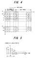
  • an inverse-Fourier-transformation unit 84 performs N-point IFFT processing on the N number of estimated channel values in the frequency range and generates a delay profile as shown in FIG. 5.
  • the graduations on the time axis of FIG. 5 are for the delay time from the direct wave, where the level P 0 at time 0 is the received level of the direct wave, the level at time 1 is the received level of the path having a delay of one symbol, the level at time 2 is the received level of the path having a delay of two symbols, and the level at time (N-1) is received level having a delay of (N-1) symbols.
  • the output from the inverse-Fourier-transformation unit 84 is the received level of each of the multi paths.
  • a multi-path-extraction unit 85 extracts the multi paths for which delay time exceeds GI, and as shown in FIG. 6, a zero-insertion unit 85 makes the received levels of (K ⁇ N-GI) number of multi paths for which the delay time exceeds Gl '0'.
  • a Fourier-transformation unit 87 performs K ⁇ N-point FFT processing on K ⁇ N number of delay profiles for which the received level of (K ⁇ N-GI) number of multi paths have been made 0, and estimates channels for K ⁇ N number of sub carriers.
  • a channel-compensation-value-generation unit 88 uses the estimated channel values to generate channel-compensation values based upon a method such as the ORC method, EGC method, MRC method, MMSE method or ZF method, and the channel-compensation unit 66 multiplies the K ⁇ N number of FFT processing results that are output from the Fourier-transformation unit 65 (FIG. 2) by the channel-compensation values to perform channel compensation.
  • a method such as the ORC method, EGC method, MRC method, MMSE method or ZF method
  • channel-compensation coefficients g k for each sub carrier are given by the inverse of the estimated channel responses H k according to the equation below. g k + 1 H k
  • the channel-compensation unit 66 performs channel correction by multiplying the received signal (K ⁇ N-point FFT output) by the channel-compensation coefficients g k , the received signal becomes x k + n k H k and channel compensation is performed.
  • SNR of each component becomes as below.
  • SNR ⁇ x 2 ⁇ n 2
  • the channel-compensation coefficients g k in the minimum mean square error method must be selected so that cost function of the following equation is minimized.
  • FIG. 7 is a flowchart of the channel-estimation process shown in FIG. 3.
  • pilot symbols are included in the transmission frame.
  • a frame is set so that the first symbols at the start of the frame are pilots P, and the remaining symbols are data D.
  • the following process is performed in order to estimate the channel response in the frequency domain.
  • N-point FFT is employed for converting the signal in the time domain to a signal in the frequency domain.
  • channel responses are estimated for correcting the channel responses for each of the N number of sub carriers (step S1).
  • step S2 a step is added in order to average the estimated values for channel distortion in both the time domain and frequency domain.
  • channel fluctuation is estimated only in the N-point frequency domain.
  • the period of guard interval is estimated well and it is possible to avoid inter-symbol interference and inter-channel interference. Therefore, channel characteristics (delay profile) are found by performing N-point IFFT processing (step S2). All meaningful paths can be extracted from the signal within the time interval [0, Gl ⁇ Td].
  • Gl is the number of discrete data that constitute the guard interval
  • Td is the period of the transmission data.
  • the period of one 0FDM symbol is equal to (Gl + N) ⁇ Td.
  • step S3 the meaningful paths are extracted (step S3).
  • Gl number of the first data are saved in memory.
  • zeros are added to and set for the rest of the frame (K ⁇ N-Gl) (step S4).
  • K ⁇ N-point FFT becomes the estimated channel values that are used for realizing the already proposed equalizer (step S5).
  • FFT that is performed by the Fourier-transformation units 81 and 87 can be replaced with DFT
  • the IFFT that is performed by the inverse-Fourier-transformation unit 84 can be replaced with IDFT.
  • FIG. 8 is a block diagram showing the construction of a different channel-estimation unit, where the same reference numbers are used for parts that are identical to those shown in FIG. 2.
  • a Fourier-transformation unit 91 uses an 0FDM symbol from which a guard interval has been removed to perform N-point FFT and generate N number of sub-carrier-signal components
  • a channel-estimation unit 92 performs the operation of Equation (15) to estimate channels for each sub carrier.
  • An averaging unit 93 performs the operation of Equation (16) to average the estimated channel values by averaging in both the time domain and frequency domain and output the results. From the above, estimated channel values are obtained for N number of sub carriers as shown in (A) of FIG. 9.
  • an estimated-channel-value-interpolation unit 94 uses the equation below to interpolate (K-1) number of estimated channel values between the adjacent estimated channel values, and calculates estimated channel values for K ⁇ N number of sub carriers according to K number of 0FDM symbols.
  • H ⁇ K ⁇ m + q f 1 K K - q ⁇ H ⁇ m + q ⁇ H ⁇ m + 1 ⁇ 0 ⁇ m ⁇ N , ⁇ 0 ⁇ q ⁇ K
  • H ⁇ Km + q f is the estimated channel value for the mth sub carrier in the K ⁇ N-point frequency domain as shown in (B) of FIG. 9.
  • a channel-compensation-value-generation unit 95 uses the estimated channel values to generate channel-compensation values based upon a method such as the ORC method, EGC method, MRC method, MMSE method or ZF method, and a channel-compensation unit multiplies the K ⁇ N number of FFT process i ng results that are output from the Fourier-transformation unit 65 by the channel-compensation values.
  • FFT was performed by the Fourier-transformation unit 91, however it is possible to replace it with DFT.
  • the invention was applied to the 0FDM communication method in which data were transmitted or received after inserting a guard interval for very K number of 0FDM symbols, however, the present invention may also be applied to the MC-CDMA communication method.
  • FIG. 10 is a block diagram showing the construction of an MC-CDMA transmission apparatus, where the same reference numbers are used for parts that are the same as those of the 0FDM transmission apparatus shown in FIG. 1.
  • This apparatus differs in that (1) there are Np number of copy units 101 1 to 101 Np that make SF number of copies of each of the Np number of data that are output from an S/P conversion unit 53 and outputs the result, and (2) there are Np number of spreading units 102 1 to 102 Np that multiply the SF number of data that are output from each copy unit by spreading codes C 1 to C SF (spreading codes having a spreading factor SF) that are unique to the user.
  • spreading codes C 1 to C SF spreading codes having a spreading factor SF
  • an encoding unit 51 encodes high-speed binary data using convolution code or turbo code, for example, and a modulation unit 52 performs interleaving after which it modulates the encoded data using a modulation method such as BPSK, QPSK or 16-QAM.
  • a modulation method such as BPSK, QPSK or 16-QAM.
  • an S/P conversion unit 53 converts the modulated data symbols and pi lot symbols to Np number of parallel low-speed data sequences, and outputs the result.
  • spreading codes C to C SF (spreading codes having a spreading factor SF) that are unique to the user
  • a switch 56c inputs K number of 0FDM symbols that are output from the P/S conversion unit 55 in order to buffers B 1 to B K , then a guard-interval-insertion unit 56b inserts a cyclic prefix CP as a guard interval Gl by copying the last G number of symbols of the Kth 0FDM symbol in front of the first 0FDM symbol as shown in (A) of FIG. 23.
  • a switch 56d reads the 0FDM symbols with guard intervals attached in order from the buffers B 1 to B K and inputs them to a digital-to-analog (DA) conversion unit 57.
  • DA digital-to-analog
  • the DA conversion unit 57 converts the 0FDM symbols that were input from the guard-interval-insertion-processing unit 56 to an analog signal, and a radio unit 58 performs up-conversion of the frequency from a baseband signal to a radio signal, after which it amplifies the signal and transmits it from an antenna 59.
  • a radio unit 58 performs up-conversion of the frequency from a baseband signal to a radio signal, after which it amplifies the signal and transmits it from an antenna 59.
  • the inverse-Fourier-transformation unit 54 performed IFFT processing, however, IDFT processing could also be performed.
  • FIG. 11 is a block diagram showing the construction of an MC-CDMA receiving apparatus, where the same reference numbers are used for parts that are the same as those of the 0FDM receiving apparatus shown in FIG. 2.
  • a bandpass filter (BPF) 61 filters the signal received from an antenna 60 and removes the unneeded frequency component
  • a down-converter (D/C) 62 converts the frequency of the radio signal to a baseband signal
  • an analog-to-digital conversion unit (not shown in the figure) converts that baseband signal from an analog signal to a digital signal
  • a guard-interval-removal unit 63 removes the guard intervals.
  • the Fourier-transformation unit 65 performs FFT processing on K ⁇ N number of time-domain-signal components and outputs K ⁇ N number of sub-carrier components.
  • a channel-estimation unit uses pilot symbols to estimate channels for each sub carrier, then generates channel-compensation values using a method such as the MMSE method or ZF method, after which a channel-compensation unit 66 multiplies the K ⁇ N number of FFT processing results by the channel-compensation values to perform channel compensation.
  • an inverse-Fourier-transformation unit 67 performs K ⁇ N-point IFFT processing at the same time for all of the K ⁇ N number of channel-compensated sub-carrier components (K number of 0FDM symbols), and outputs K ⁇ N-point time-domain-signal components in parallel.
  • K number of N-point Fourier-transformation units 68 1 to 68 K divide the K ⁇ N number of time-domain-signal components that were output in parallel from the inverse-Fourier-transformation unit 67 into divisions of N number of components each and perform N-point FFT processing on each division.
  • each of the Fourier-transformation units 68, to 68 K generates N number of sub-carrier components.
  • Np number of inverse-spreading units 201 1 to 201 Np , 201 Np+1 to 201 2 ⁇ Np , ... , 201 (K-1) ⁇ Np+1 to 201 K ⁇ Np are connected to each of the Fourier-transformation units 68 1 to 68 K .
  • Np and adder units 202 Np+1 to 202 2 ⁇ Np , ..., 202 (K-1) ⁇ Np+1 to 202 K ⁇ Np similarly perform the same operation so that Np number of data are output from each.
  • a P/S conversion unit 69 serially outputs in order K groups of Np number of symbols that were input from each adder unit, then a demodulation unit 70 demodulates the input signal using a demodulation method such as BPSK, QPSK and 16QAM, and a decoding unit 71 performs deinterleaving after which it decodes and outputs the input data.
  • a demodulation unit 70 demodulates the input signal using a demodulation method such as BPSK, QPSK and 16QAM
  • a decoding unit 71 performs deinterleaving after which it decodes and outputs the input data.
  • the FFT processing performed by the Fourier-transformation unit 65 and N-point Fourier-transformation units 68 1 to 68 K can be replaced by DFT processing
  • the IFFT processing performed by the inverse-Fourier-transformation unit 67 can be replaced by IDFT processing.
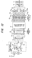
  • FIG. 12 is a block diagram showing a second embodiment of the construction of an MC-CDMA receiving apparatus, where the same reference numbers are used for parts that are the same as those of the MC-CDMA receiving apparatus shown in FIG. 11.
  • This apparatus differs in that the K ⁇ N-point inverse-Fourier-transformation unit 67 and K number of N-point Fourier-transformation units 68 1 to 68 K are removed, and there is a batch-transformation-processing unit 301 that performs the K ⁇ N-point IFFT processing and N-point FFT processing together.
  • the batch transformation performed by the batch-transformation-processing unit 301 was explained above using Equations (12) to (14), however, it will be explained in more detail here.
  • the IFFT processing results and FFT processing results can be respectively expressed by following equations.
  • the batch-transformation-processing unit 301 multiplies the N-row by K ⁇ N-column matrix W by a K ⁇ N x 1 vector x ⁇ n , it is possible to generate results that are the same as the results obtained by performing the IFFT operation and K number of FFT operations shown in FIG. 11. After that, it is possible to demodulate and decode the
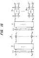
  • FIG. 14 is a block diagram showing the construction of a third embodiment of an MC-CDMA receiving apparatus, where the same reference numbers are used for parts that are the same as those of the MC-CDMA receiving apparatus shown in FIG. 11.
  • This apparatus differs in that the K ⁇ N -point Fourier-transformation unit 65, channel-compensation unit 66, K ⁇ N -point inverse-Fourier-transformation unit 67 and K number of N-point Fourier-transformation uni ts 68, to 68 K shown in FIG.
  • a multi-carrier receiving method and multi-carrier receiving apparatus and a channel-estimation method and channel-estimation apparatus for a communication system in which transmission is performed after inserting a guard interval for every K number of multi-carrier transmission symbols (for example, K number of 0FDM symbols). Also, with this invention, transmission and reception are performed after inserting a guard interval for every K number of multi-carrier transmission symbols, so it is possible to improve the efficiency of data transmission.

Landscapes

  • Engineering & Computer Science (AREA)
  • Computer Networks & Wireless Communication (AREA)
  • Signal Processing (AREA)
  • Power Engineering (AREA)
  • Physics & Mathematics (AREA)
  • Discrete Mathematics (AREA)
  • General Physics & Mathematics (AREA)
  • Mathematical Physics (AREA)
  • Mobile Radio Communication Systems (AREA)
  • Cable Transmission Systems, Equalization Of Radio And Reduction Of Echo (AREA)

Abstract

In a multi-carrier communication method that receives and demodulates a signal to which a guard interval has been attached for every group of a plurality of multi-carrier transmission symbols, the present invention removes the guard intervals from the received signal, performs Fourier-transformation processing together for the plurality of multi-carrier transmission symbols, estimates channels for sub carriers that correspond to the plurality of multi-carrier transmission symbols, performs channel compensation on the Fourier-transformation results based on the channel-estimation results, performs inverse-Fourier-transformation processing together on the plurality of channel-compensated multi-carrier transmission symbols, performs Fourier-transformation processing on the inverse-Fourier-transformation results for every multi-carrier transmission symbol and demodulates the received signal.

Description

    Technical Field
  • The present invention relates to a mul ti-carrier receiving method and multi-carrier receiving apparatus, and more particularly to a multi-carrier receiving method and multi-carrier receiving apparatus in a multi-carrier communication system that receives and demodulates a signal to which a guard interval has been attached to every group of a plurality of multi-carrier-transmission symbols.
  • Background Art
  • The multi-carrier modulation method has gained much attention as a next-generation mobile-communication system. By using the multi-carrier modulation system, not only is it possible to improve high-speed transmission in a wide bandwidth, but by making each of the sub-carriers have a narrow bandwidth, it is possible to reduce the effect of frequency-selective fading.
    Also, by using an orthogonal frequency division multiplexing (0FDM) system, not only is it possible to improve the frequency utilization efficiency, but it is also possible to eliminate the effect of inter-symbol interference by using a guard interval for each 0FDM symbol.
  • The theory of the 0FDM system is to reduce the bit rate of each of the sub carriers, and use many of these low-bit-rate sub carriers to provide high-bit-rate transmission. The frequency bandwidth is divided into small ranges, and each of the ranges is used as the frequency for each of the respective low-bi t-rate sub carriers. The sub carriers are orthogonal to each other. In order to obtain these characteristics, the sub-carrier frequencies must be separated by a multiple of the inverse of the symbol period. The multi-carrier modulation system does not receive the effect of frequency-selective fading, however, channels are estimated for each sub carrier, and channel compensation must be performed.
  • - 0FDM Transmission Apparatus
  • FIG. 16 is a block diagram showing the construction of an 0FDM transmission apparatus that uses a conventional 0FDM transmission system. An encoding unit 1 encodes high-speed binary data using convolution code or turbo code, for example, and after interleaving, a modulation unit 2 performs modulation, such as BPSK, QPSK or 16-QAM modulation of the encoded data. Next, a serial-to-parallel conversion unit (S/P conversion unit) 3 converts the modulated data symbols and pilot symbols to parallel low-speed modulated data sequences having N symbols, and generates N number of sub-carrier components.
    An N-point inverse fast Fourier-transformation unit 4 performs inverse-fast-Fourier transformation (IFFT) on the N number of modulated symbols (sub-carrier components) that are output from the S/P conversion unit 3 and performs parallel output of N number of time-domain-signal components. A parallel-to-serial conversion unit (P/S conversion unit) 5 converts the N number of time-domain-signal components that were obtained from the IFFT process to a serial signal and outputs the result as an 0FDM symbol. A guard-interval-insertion unit 6 inserts a guard interval Gl into this 0FDM symbol, and a digital-to analog conversion unit (D/A) 7 converts the signal that is output from the guard-interval-insertion unit 6 to an analog signal, after which a radio unit 8 performs up-conversion of the frequency of the baseband signal to that of a radio signal, then amplifies and transmits that signal from an antenna 9. The case of employing fast-Fourier transformation FFT and inverse-fast-Fourier transformation IFFT for the Fourier transformation and inverse Fourier transformation will be explained below, however, it is also possible to employ discrete-Fourier transformation DFT and inverse-discrete transformation IDFT; with the same being true in the embodiments.
  • FIG. 17 is a drawing showing frame configuration, where a pilot P is time multiplexed in front of the transmission data for one frame (the pilot P can be dispersed inside the frame). By taking the pilot per frame to be 4 x N symbols, and the transmission data to be 28 x N symbols, the N symbols of the pilot are output as parallel data the first 4 times from the S/P conversion unit 3, and after that, the N symbols of the transmission data are output as parallel data the next 28 times. As a result, during the period of one frame, it is possible to time multiplex the pilot onto N number of sub carriers and transmit them 4 times, and then on the receiving side, it becomes possible to use the pilot to estimate a channel and perform channel compensation (fading compensation) for each sub carrier.
    FIG. 18 is a drawing explaining the insertion of guard intervals. At time of the insertion of a guard interval, the IFFT output signal that corresponds to N number of sub-carrier samples (= 1 0FDM symbol) is regarded as one unit, and the end portion of that 0FDM symbol is copied and placed at the beginning of the 0FDM symbol. By inserting the guard interval, it becomes possible to eliminate the effect of inter-symbol interference due to multi paths.
  • When considering an 0FDM symbol that transmits N number of symbols s n i n = 0 N - 1
    Figure imgb0001
    in the ith 0FDM symbol period by way of N number of sub carriers, the baseband 0FDM signal that is transmitted in the ith block is expressed by the following equation. x k i = 1 N n = 0 N - 1 s n i exp j 2 πnk N 0 k < N
    Figure imgb0002

    Here, s n i
    Figure imgb0003
    is the N number of symbols that are transmitted in the ith 0FDM symbol, N is the block size, and j = - 1 .
    Figure imgb0004
  • In order to realize an 0FDM system that has no ISI (inter-symbol interference) or ICI (inter-channel interference), a guard interval is inserted in each of the 0FDM symbols. Depending on the configuration of the guard intervals (for example a cyclic prefix CP), the delayed signal, having a delay time that is less than the guard-interval period G, does not cause the ISI. A transmission signal having guard intervals can be expressed by the following equation. x ˜ k i = { x N - G + k i 0 k < G x k - G i G k < N + G
    Figure imgb0005

    Here, G is the length of the guard intervals, 0 ≦ k < G is the guard-interval period, and G ≦ k < N + G is the data period.
  • - Frequency-selective Channel
  • Supposing that a propagation channel is constructed from P number of paths (channels) having different amplitudes and delay characteristics, the impulse response can be expressed by the following equation. h t τ = p = 0 P - 1 α p t δ τ - τ p
    Figure imgb0006

    Here, αp and τp are the channel gain and delay time of the pth path. Furthermore, in order for simulation, the total channel power is taken to be equal to '1'. Actually, in the case where coherent detection is possible, or in other words, when timing is perfect, there is never any interference that is greater than one 0FDM symbol. In the frequency domain, the channel-transmission function H(f,t) is expressed by the following equation. H f t = p = 0 P - 1 α p exp - j 2 πf τ p
    Figure imgb0007
  • - 0FDM Receiving Apparatus
  • FIG. 19 is a block diagram showing the construction of an 0FDM receiving apparatus that uses a conventional 0FDM receiving system. A bandpass filter (BPF) 11 filters a signal received from an antenna 10 and removes the unnecessary frequency component, then a down converter (D/C) 12 converts the frequency from a radio signal to a baseband frequency, an analog-to-digital conversion unit (not shown in the figure) converts that baseband signal from an analog to a digital signal, and a guard-interval-removal unit 13 removes the guard intervals. An S/P conversion unit 14 converts the time-domain-signal from which guard intervals have been removed to N number of parallel data, and inputs the result to an N=point Fourier-transformation unit 15. The Fourier-transformation unit 15 performs N-point FFT processing on the N number of time-domain-signal components and outputs N number of sub-carrier components. In order to reduce the effect of channel distortion, a channel-estimation unit (not shown in the figure) performs well-known channel-estimation calculation and estimates channels for the sub carriers, then generates channel-compensation values for the frequency range of each sub carrier using a minimum mean square error (MMSE) method or zero forcing (ZF) coefficient method, then a channel-compensation unit 16 multiplies the N number of FFT transformation results by the channel-compensation values to perform channel compensation. Finally, a P/S conversion unit 17 serially outputs in order the N number of channel-compensated sub-carrier components, a demodulation unit 18 performs demodulation such as BPSK, QPSK or 16QAM demodulation on the input signal, and a decoding unit deinterleaves the signal after which it decodes the input signal and outputs the result.
  • In the case where the length of the guard interval is greater than the maximum delay, the received baseband signal is expressed by the following equation (refer to non-patent document 1). r k i = p = 0 P - 1 α p x k - τ p i + n ˜ k i 0 k < N
    Figure imgb0008

    He re, r i = r 0 r N - 1 i T
    Figure imgb0009
    and n ˜ i = n ˜ 0 i n ˜ N - 1 i T
    Figure imgb0010
    are the rece i ved signal and AWGN (Additive White Gaussian Noise), respectively, of the ith 0FDM symbol after guard intervals have been removed. Finally, demodulation is performed and the information bits are evaluated.
  • As explained above, channel fluctuation is corrected for each sub carrier. In the case of IEEE standards 802. 11g and 802. 11a, the dimension for IFFT and FFT is N = 64(64 sub carriers), and of these, only 48 sub carriers are used for the transmission of data symbols and 4 sub carriers are used for synchronizing the data frames in the frequency range. Twelve of the sub carriers are not used. Channel estimation and compensation is performed for the sub carriers that are used.
  • - MC-CDMA Transmission Apparatus
  • In multi-carrier CDMA (MC-CDMA), CDMA technology is built into the 0FDM modulation in order for multiple access. Data from each user is spread by orthogonal spreading code in the frequency domain and multiplexed with different spread data from other users.
    FIG. 20 is a block diagram showing the construction of an MC-CDMA transmission apparatus, where the same reference numbers are used for parts that are identical to those of the 0FDM transmission apparatus shown in FIG. 16. This MC-CDMA transmission apparatus differs in that: (1) there are Np number of copy units 211 to 21Np that copy SF number at a time each of the Np number of data that are output from the S/P conversion unit 3, and (2) there are Np number of spreading units 221 to 22Np that respectively multiply the SF number of data that are output from each copy unit by spreading codes C, to CSF (spreading code having a spreading factor SF) that are unique to each user.
  • In other words, an encoding unit 1 encodes high-speed binary data using convolution code or turbo code for example, and a modulation unit 2 modulates the encoded data using BPSK, QPSK or 16-QAM modulation. Next, a serial-to-parallel conversion unit (S/P conversion unit) 3 converts the modulated data symbols and pilot symbols to Np number of parallel low-speed modulated data sequences, and outputs the result.
    Np number of copy units 211 to 21Np copy and output SF number at a time each of the Np number of symbols that are output in parallel from the S/P conversion unit 3, Np number of spreading units 221 to 22Np respectively multiply the SF number of symbols that are output from each copy unit by spreading codes (spreading code having a spreading factor SF) C, to CSF that are unique to each user, an inverse-Fourier-transformation unit 4 performs IFFT processing on N (N = Np x SF) number of sub-carrier components, and a P/S conversion unit 5 serially outputs in order N number of time-domain-signal components (0FDM symbol).
    A guard-interval-insertion unit 6 inserts a guard interval into the 0FDM symbol, a digital-to-analog conversion unit (D/A) converts the signal that is output from the guard-interval-insertion uni t 6 to an analog signal, and a radio unit 8 performs up-conversion of the frequency from a baseband signal to a radio signal, after which it amplifies the signal and transmits it into space from an antenna 9.
  • - MC-CDMA Receiving Apparatus
  • FIG. 21 is a block diagram showing the construction of a conventional MC-CDMA receiving apparatus, where the same reference numbers are used for parts that are identical to those of the 0FDM receiving apparatus shown in FIG. 19. The MC-CDMA receiving apparatus differs in that: (1) there are Np number of inverse-spreading units 231 to 23Np that separate the N (N = Np x SF) number of sub-carrier components that are output from the channel-compensation unit 16 SF number by SF number at a time into Np number of groups, and multiplies each group respectively by spreading codes C, to CSF (spreading code having a spreading factor SF) that are unique to each user; and (2) there are Np number of adder units 241 to 24Np that add the SF number of inverse-spread data that are output from each inverse-spreading unit 231 to 23Np.
    In other words, a bandpass filter (BPF) 11 filters a signal that is received from the antenna 10 and removes the unnecessary frequency component, then a down-conversion unit (D/C) 12 converts the frequency of the radio signal to a baseband frequency, an analog-to-digital conversion unit (not shown in the figure) converts the baseband signal from analog to digital, and a guard-interval-removal unit 13 removes the guard intervals. An S/P conversion unit 14 converts the time-domain-signal from which the guard intervals have been removed to N number of parallel data, and inputs the result into an N-point Fourier-transformation unit 15. The Fourier-transformation unit 15 performs FFT processing on the N number of time-domain-signal components and outputs N number of sub-carrier components. A channel-estimation unit (not shown in the figure) uses pi lot symbols to estimate channels for each sub carrier, and using these estimated channel values generates channel-compensation values by any one of an orthogonal restoring combining (ORC) method, equal gain combining (EGC) method, maximum ratio combining (MRC) method, MMSE method and ZF method, and a channel-compensation unit multiplies the N (N = Nc x SF) number of FFT processing results by the channel compensation values to perform channel compensation.
  • The Np number of inverse spreading units 231 to 23Np separate the N (N = Np x SF) number of sub-carrier components that are output from the channel-compensation unit 16 SF number by SF number at a time into Np number of groups and performs inverse spreading by respectively multiplying each group by spreading codes C1 to CSF (spreading code having a spreading factor SF) that are unique to each user, and adder units 241 to 24Np add each of the SF number of inverse-spread data that are output from each of the inverse-spreading units 231 to 23Np and output Np number of data. A P/S conversion unit 17 serially outputs in order Np number of inverse-spread symbols, then a demodulation unit 18 demodulates the input symbols using BPSK, QPSK or 16QAM demodulation, and a decoding unit 19 performs deinterleaving after which it decodes and outputs the input data. The 0FDM transmission system is a special case of the MC-CDMA transmission system in which SF = 1.
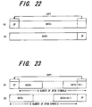
  • In the explanation above, and as shown in (A) of FIG. 22, a cyclic prefix CP is inserted as a guard interval by copying the end portion of an 0FDM symbol at the beginning of the 0FDM symbol, however, as shown in (B) of FIG. 22, it is also possible to insert a zero-padding section ZP as a guard interval in which a specified bit length at the end of the 0FDM symbol is filled in with '0's. Also, it is not shown in the figures, however, it is also possible to insert a unique word having a known bit length as a guard interval in the place of inserting '0' s.
    As described above, by inserting guard intervals for each 0FDM symbol, it is possible to eliminate the effect of inter-symbol interference due to multi paths (delayed waves), however, there is a problem in that the data-transmission efficiency becomes poor.
  • In order to prevent the data-transmission efficiency from becoming poor, methods have been proposed such as shown in (A) of FIG. 23 in which a cyclic prefix CP is inserted as a guard interval for every K number of 0FDM symbols, or as shown in (B) of FIG. 23 in which a zero-padding section is inserted as a guard interval for every K number of 0FDM symbols (refer to non-patent document 2).
    However, in the document referenced above, an 0FDM transmission apparatus is disclosed that inserts a guard interval for every K number of 0FDM symbols and performs transmission, however it does not describe the construction of an 0FDM receiving apparatus or a method of performing channel estimation.
  • Taking the aforementioned into consideration, the objective of the present invention is to provide a multi-carrier receiving method and apparatus, and a channel-estimation method and apparatus for a multi-carrier communication system that inserts a guard interval for every K number of multi-carrier transmission symbols before performing transmission.
    Another objective of the present invention is to improve the data transmission on efficiency by inserting a guard interval for every K number of multi-carrier transmission symbols and transmitting them.
    Still another objective of the present invention is to effectively perform channel compensation and accurately demodulate transmission data in a multi-carrier communication system that inserts a guard interval for every K number of multi-carrier transmission symbols before performing transmission.
  • Non-patent Document 1:
  • Disclosure of the Invention
  • A first feature of the present invention is a multi-carrier receiving method in a multi-carrier communication system that receives and demodulates a signal to which a guard interval has been attached for every group of a plurality of multi-carrier transmission symbols that comprises steps of removing guard intervals from a received signal, performing Fourier-transformation processing for every group of a plurality of multi-carrier transmission symbols, estimating channels for sub carriers that correspond to the plurality of multi-carrier transmission symbols, performing channel compensation on the Fourier-transformation results based on the channel-estimation results, performing inverse-Fourier-transformation processing together for every group of the plurality of channel-compensated multi-carrier transmission symbols, performing Fourier-transformation processing on the inverse-Fourier-transformation results for every multi-carrier transmission symbol and demodulates the received signal.
    In the method described above, the step of estimating channels includes sub-steps of estimating channels for N number of sub carriers using a multi-carrier transmission symbol from which the guard interval has been removed, and interpolating (K-1) number of estimated channel values between the adjacent estimated values to obtain estimated channel values for K · N number of sub carriers that correspond to the aforementioned plurality of multi-carrier transmission symbols. Also, the step of estimating channels includes sub-steps of estimate channels for N number of sub carriers using a multi-carrier transmission symbol from which the guard interval has been removed, then performing N-point inverse-Fourier-transformation processing on the estimated channel values for those N number of sub carriers and creating a delay profile that indicates the mul ti-path receiving levels, after which making the receiving levels of paths that exceed the guard-interval period GI of that delay profile zero and performing K · N-point Fourier-transformation processing on that delay profile that has been made zero to estimate channels for K · N number of sub carriers that correspond to the plurality of multi-carrier transmission symbols.
  • A second feature of the present invention is a multi-carrier receiving apparatus in a multi-carrier communication system that receives and demodulates a signal to which a guard interval has been attached for every group of a plurality of (=K number of) multi-carrier transmission symbols.
    A first multi-carrier receiving apparatus comprises: a guard-interval removal unit that removes guard intervals from a received signal; a Fourier-transformation unit that performs Fourier-transformation processing together on each group of a plurality of multi-carrier transmission symbols from which a guard interval has been removed; a channel-estimation/compensation unit that estimates channels for sub carriers that correspond to the plurality of multi-carrier transmission symbols and performs channel compensation based on the channel-estimation results; an inverse-Fourier-transformation unit that performs inverse Fourier transformation together on the plurality of channel-compensated multi-carrier transmission symbols; a Fourier-transformation unit that performs Fourier-transformation processing on the inverse-Fourier-transformation results for each multi-carrier transmission symbol; and a demodulation unit that demodulates the transmission data based on those Fourier-transformation results.
    A second multi-carrier receiving apparatus comprises: a guard-interval removal unit that removes guard intervals from a received signal; a Fourier-transformation unit that performs Fourier-transformation processing together on each group of a plurality of multi-carrier transmission symbols from which a guard interval has been removed; a channel-estimation/compensation unit that estimates channels for sub carriers that correspond to the plurality of multi-carrier transmission symbols and performs channel compensation based on the channel-estimation results; a processing unit that performs inverse Fourier transformation together on the plurality of channel-compensated multi-carrier transmission symbols, as well as performs Fourier-transformation processing on the inverse-Fourier-transformation results for each multi-carrier transmission symbol; and a demodulation unit that demodulates the transmission data based on those processing results.
    A third multi-carrier receiving apparatus comprises: a guard-interval removal unit that removes guard intervals from a received signal; a processing unit that performs Fourier-transformation processing together on each group of a plurality of multi-carrier transmission symbols from which a guard interval has been removed, estimates channels for sub carriers that correspond to the plurality of multi-carrier transmission symbols, performs channel compensation based on the channel-estimation results, performs inverse Fourier transformation together on the plurality of channel-compensated multi-carrier transmission symbols, and performs Fourier-transformation processing on the inverse-Fourier-transformation results for each multi-carrier transmission symbol; and a demodulation unit that demodulates the transmission data based on those processing results.
    In the multi-carrier receiving apparatuses described above, the channel-estimation/compensation unit comprises: means for estimating channels for N number of sub carriers using a multi-carrier transmission symbol from which a guard interval has been removed; and means for interpolating (K-1) number of estimated channel values between the adjacent estimated channel values and obtaining estimated channel values for K · N number of sub carriers that correspond to said plurality of multi-carrier transmission symbols.
    Also, in the multi-carrier receiving apparatuses described above, the channel-estimation/compensation unit comprises: means for estimating channels for N number of sub carriers using a multi-carrier transmission symbol from which a guard interval has been removed; means for performing N-point inverse-Fourier-transformation processing on the estimated channel values for N number of sub carriers and creating a delay profile that indicates the multi-path receiving levels; means for making the receiving level of paths that exceed the guard-interval period GI of the delay profile zero; and means for performing K · N-point Fourier-transformation processing on the delay profile that has been made zero to estimate channels for K · N number of sub carriers that correspond to said plurality of multi-carrier transmission symbols.
  • Brief Description of the Drawings
    • FIG. 1 is a block diagram showing the construction of an 0FDM transmission apparatus in an 0FDM communication system that inserts a guard interval for every K number of multi-carrier transmission symbols before performing transmission.
    • FIG. 2 is a block diagram showing the construction of an 0FDM receiving apparatus in an 0FDM communication system that inserts a guard interval for every K number of multi-carrier transmission symbols before performing transmission.
    • FIG. 3 is a block diagram showing the construction of a channel-estimation unit.
    • FIG. 4 is a drawing explaining a process for averaging estimated channel values.
    • FIG. 5 is a drawing explaining a delay profile.
    • FIG. 6 is a drawing explaining a process for inserting zeros.
    • FIG. 7 is a flowchart showing a channel-estimation process.
    • FIG. 8 is a block diagram showing different construction of a channel-estimation unit.
    • FIG. 9 is a drawing explaining a process for interpolating estimated channel values.
    • FIG. 10 is a block diagram showing the construction of an MC-CDMA transmission apparatus.
    • FIG. 11 is a block diagram showing the construction of an MC-CDMA receiving apparatus.
    • FIG. 12 is a block diagram showing the construction of a second embodiment of an MC-CDMA receiving apparatus.
    • FIG. 13 is a drawing explaining the Fourier transformation process of a second embodiment of an MC-CDMA receiving apparatus.
    • FIG. 14 is a block diagram showing the construction of a third embodiment of an MC-CDMA receiving apparatus.
    • FIG. 15 is a drawing explaining the Fourier transformation process of a third embodiment of an MC-CDMA receiving apparatus.
    • FIG. 16 is a block diagram showing the construction of an 0FDM transmission apparatus in a conventional 0FDM transmission system.
    • FIG. 17 is a drawing showing the configuration of a frame.
    • FIG. 18 is a drawing explaining a process for inserting guard intervals.
    • FIG. 19 is a block diagram showing the construction of an 0FDM receiving apparatus in a conventional 0FDM receiving system.
    • FIG. 20 is a block diagram showing the construction of a conventional MC-CDMA transmission apparatus.
    • FIG. 21 is a block diagram showing the construction of a conventional MC-CDMA receiving apparatus.
    • FIG. 22 is a drawing explaining a conventional process for inserting guard intervals (cyclic prefixes, zero-padding sections).
    • FIG. 23 is a drawing explaining a proposed process for inserting guard intervals (cyclic prefixes, zero-padding sections).
    Best Mode for Carrying Out the Invention (A) Embodiment 1 (a) 0FDM Transmission Apparatus
  • FIG. 1 is a block diagram showing the construction of an 0FDM transmission apparatus in an 0FDM communication system that inserts guard intervals for every K number of multi-carrier transmission symbols before performing transmission.
    An encoding unit 51 encodes high-speed binary data using convolution code or turbo code, for example, and a modulation unit 52 performs interleaving, after which it modulates the encoded data using a modulation method such as BPSK, QPSK or 16-QAM. Next, a serial-to-parallel conversion unit (S/P conversion unit) 53 converts the modulated data symbols and pi lot symbols to a parallel low-speed modulated data sequence of N symbols and generates N number of sub-carrier components.
  • An N-point inverse-fast-Fourier-transformation unit 54 performs inverse-fast-Fourier transformation (IFFT) on the N number of modulated signals (sub-carrier components) that are output from the S/P conversion unit 53, and outputs N number of time-domain-signal components in parallel. A P/S conversion unit 55 converts the N number of time-domain-signal components that are obtained from IFFT processing to a serial signal and outputs the result as an 0FDM symbol. In other words, the 0FDM symbol comprises N number of symbols. The inverse-fast-Fourier-transformation unit 54 of this example uses an apparatus that performs IFFT (inverse fast Fourier transformation), however, an apparatus that performs IDFT (inverse direct Fourier transformation) could also be used.
    A guard-interval-insertion-processing unit 56 inserts a guard interval consisted of G number of symbols for each group of K number of 0FDM symbols, and comprises a buffer unit 56a having a capacity of (K · N + G), and a guard-interval-insertion unit 56b. A switch 56c inputs the K number of 0FDM symbols that are output from the P/S conversion unit 55 in order to buffers B1 to BK, and as shown in (A) of FIG. 23, the guard-interval-insertion unit 56b inserts a cyclic prefix CP as a guard interval Gl by copying the last G number of symbols of the Kth 0FDM symbol to in front of the first 0FDM symbol. Next, a switch 56d reads the 0FDM symbols with guard interval attached in order from the buffers B1 to BK and inputs them to a digital-to-analog (DA) conversion unit 57.
    The DA conversion unit 57 converts the 0FDM symbols that were input from the guard-interval-insertion-processing unit 56 to an analog signal, and a radio unit 58 performs up-conversion of the frequency from a baseband signal to a radio signal, after which it amplifies the signal and transmits it from an antenna 59
    The construction of this 0FDM transmission apparatus was explained as using inverse-fast-Fourier transformation (IFFT) by the inverse-fast Fourier-transformation unit 54, however, it is also possible to use inverse-discrete-Fourier transformation (IDFT).
  • (b) 0FDM Receiving Apparatus
  • FIG. 2 is a block diagram showing the construction of an 0FDM receiving apparatus in an 0FDM communication system that inserts guard intervals for every K number of multi-carrier transmission symbols before performing transmission.
    A bandpass filter (BPF) 61 filters the signal received from an antenna 60 and removes the unneeded frequency component, then a down-converter (D/C) 62 converts the frequency of the radio signal to a baseband frequency, and an analog-to-digital conversion unit (not shown in the figure) converts that baseband signal from an analog signal to a digital signal. A guard-interval-removal-processing unit 63 removes the guard interval that was inserted into the received signal, and comprises a buffer unit 63a having a capacity of (K · N + G) symbols, and guard-interval-removal unit 63b. A switch 63c inputs the K number of input 0FDM symbols in order into buffers B1 to BK, and the guard-interval-removal unit 63b removes the guard interval GI that was inserted in front of the first 0FDM symbol, then a switch 63d reads the K number of 0FDM symbols in order from the buffers B1 to BK, and inputs them to a S/P conversion unit 64.
    The S/P conversion unit 64 converts the K · N-point time-domain-signal components from which the guard interval has been removed to K · N number of parallel data, and inputs the result to a K · N-point Fourier-transformation unit 65. The Fourier-transformation unit 65 performs FFT on the K · N number of time-domain-signal components, and outputs K · N number of sub-carrier components. A channel-estimation unit (described later) performs channel estimation in order to reduce the effect of channel distortion, and estimates channels for K · N number of sub carriers, then generates a channel-compensation value in the frequency domain for each sub carrier using a method such as the minimum mean square error (MMSE) method, or zero forcing (ZF) coefficient method, and a channel-compensation unit 66 multiplies the K · N number of FFT processing results by the channel-compensation values to perform channel compensation.
  • Next, an inverse-Fourier-transformation unit 67 performs K · N-point IFFF processing all together for the K · N number of channel-compensated sub-carrier components (K number of 0FDM symbols), and outputs K · N-point time-domain-signal components in parallel. Next, K number of N-point Fourier-transformation units 681 to 68K divide up the K · N number of time-domain-signal components that were output in parallel from the inverse-Fourier-transformation unit 67 into divisions of N number of components each, and perform N-point FFT processing on each division. As a result, each Fourier-transformation unit 681 to 68K generates N number of sub-carrier components. This total of K · N number of sub-carrier components corresponds to the K · N number of transmission symbols that were transmitted by the transmitting side.
    A P/S conversion unit 69 serially outputs in order K number of groups of N number of symbols that were input from the Fourier-transformation uni ts 681 to 68K, then a demodulation unit 70 demodulates the input signal using a demodulation method such as BPSK, QPSK or 16QAM, and a decoding unit 71 deinterleaves the signal after which it decodes and outputs the input data.
  • To summarize the above description, in an 0FDM receiving apparatus, an S/P conversion unit 64 converts data to a parallel stream, after which K · N-point FFT processing is performed. Next, the effect due to the channel on each sub carrier is reduced by channel compensation, and finally, before demodulating and decoding the received signal, K · N-point IFFT is performed, and the signal is divided into K number of data streams, and N-point FFT calculation is performed for each of the K number of data streams.
    The theory of the 0FDM communication system of this invention is to compensate for channel fluctuation immediately after performing K · N-point FFT calculation in order to reduce the impact of interfering components. Here, K is the insertion period of the guard intervals and N is the dimension of IFFT in the transmission unit. In the receiving unit, by performing K · N -point FFT calculation, it is possible to reduce the effect of multi paths without inter-channel interference (ICI) occurring at all.
    In the description above, a cyclic prefix is inserted as a guard interval for every K number of symbols, however, it is also possible to insert a zero-padding section or a unique word having a specified length for every K number of symbols, or even insert a combined cyclic prefix CP and unique word.
    Moreover, in the construction of the 0FDM receiving apparatus, it is possible for the K · N-point Fourier-transformation unit 65 to perform K · N-point DFT instead of K · N-point FFT, the inverse-Fourier-transformation unit 67 to perform IDFT instead of IFFT and for the Fourier-transformation units 681 to 68K to perform DFT instead of FFT.
  • (c) Mathematical Description
  • The main feature of the present invention is that in order to completely avoid inter-symbol interference or inter-channel interference, FFT processing is performed together for all of the K number of 0FDM symbols after the guard intervals have been removed, and then channel compensation is performed, after which inverse- Fourier transformation is performed together for all of the K number of channel-compensated multi-carrier transmission symbols, and Fourier-transformation processing is performed on the inverse-Fourier-transformation results for each multi-carrier transmission symbol.
    The FFT dimension of the receiving unit depends on how many symbols there are in each period for which the guard intervals are inserted. For example, by taking N to be the dimension for IFFT in the transmission unit, or in other words, by taking N to be the dimension of the frequency-multiplexing unit of the transmission unit, and supposing that guard intervals are inserted for every K number of 0FDM symbols, then the dimension for FFT in the receiving unit is equal to K · N points. If the guard intervals (CP or ZP) are estimated accurately, the output of K · N-point FFT is given by the following equation. y i KN = H i KN u i KN + n i KN
    Figure imgb0011

    Where, y i , m KN = y i , 0 KN , y i , 1 KN , y i , KN - 1 KN T
    Figure imgb0012

    is the received signal in the frequency domain after guard intervals have been removed; H i KN = H i , 0 KN , H i , 1 KN , H i , KN - 1 KN T
    Figure imgb0013

    is the channel response in the K · N-point frequency domain; u i KN = u i , 0 KN , u i , 1 KN , u i , KN - 1 KN T
    Figure imgb0014

    is the transmission signal in the K · N-point frequency domain; and n i KN
    Figure imgb0015

    is the additive white Gaussian noise (AWGN).
  • The next step is to equalize the received signal (channel estimation/compensation) in order to reduce the effect of channel distortion.
    Estimated channel values in the K · N-point frequency domain are given by the following equation. H ˜ i KN = H ˜ i , 0 KN , H ˜ i , 1 KN , H ˜ i , KN - 1 KN T
    Figure imgb0016

    Two methods for accurately estimating channel fluctuation will be described later.
  • The output from the channel equalizer can be expressed by the following equation. z i KN = H ˜ i KN - 1 y i KN
    Figure imgb0017

    When Equation (6) above is substituted in, the equation becomes as shown below. z i KN = H ˜ i KN - 1 H i KN u i KN + H ˜ i KN - 1 n i KN
    Figure imgb0018

    In the case where perfect estimation is possible, the equation becomes as follows. z i KN = u i KN + ε i KN
    Figure imgb0019

    Here, ε i KN
    Figure imgb0020
    is the noise in the equalizer output.
  • In order to demodulate the signal and accurately decode the received data, the processed data must be changed from the K · N-point frequency domain to the N-point frequency domain. In order to perform the operation of this step, K · N-point IFFT is performed once, and N-point FFT is performed K times in succession as shown in FIG. 2.
    From the K · N-point IFFT calculation by the inverse-Fourier-transformation unit 67, the K · N-point time-domain-signal components are determined by the following equation. v i , k KN = 1 K N m = 0 KN - 1 z i , m KN exp j 2 πnk K N 0 k < K N
    Figure imgb0021

    The K · N-point time-domain-signal components are divided into divisions of N number of components each, and when N-point FFT processing is performed respectively for each division by the Fourier-transformation units 681 to 68K, K · N number of sub-carrier-signal components, or in other words, K · N number of transmission symbols are determined by the following equation. x a K + b , m N = 1 N k = 0 N - 1 v a , b N + m KN exp j 2 πmk N 0 m < N
    Figure imgb0022

    Here, a and b are integers that are defined such that { 0 b < K 0 a < A
    Figure imgb0023

    and AK = I. I is the number of 0FDM symbols per frame. Finally, the N-point FFT results are demodulated and decoded.
  • (d) Variation
  • Using batch operation, it becomes possible to process all of the operations for K · N-point IFFT and N-point FFT described above (operations of Equations (10) and (11)) together. After performing compensation for channel distortion, it becomes necessary to reduce the data dimension in the frequency domain. In order to accomplish this, the K · N-point sub-carrier signals are converted to an N-point signal stream by matrix conversion.
    An N row by K · N column conversion matrix is given by W N * KN = w p , k 0 p < N , 0 k < K N
    Figure imgb0024

    and using this conversion matrix, Equation (11) can be expressed by the equation below. x ˜ a K + b N = W N * KN z a KN
    Figure imgb0025

    Here, the p row and k column elements w p , k
    Figure imgb0026

    are given by the following equation w p , k = β m = 0 N - 1 e - j 2 π N pm e j 2 π N m + N k
    Figure imgb0027

    where β is a normalization factor. Through simplification w m , p
    Figure imgb0028

    is expressed by the following equation. w m , p = { β e j 2 π K p b if p K - m = 0 β e j 2 π K p b 1 - e j 2 π p K - m 1 - e j 2 π N p K - m if p K - m 0
    Figure imgb0029

    Therefore, it is possible to replace the K · N-point inverse-Fourier-transformation unit 67 and K number of N-point Fourier transformation units 681 to 68K shown in FIG. 2 with a processing unit that performs the operation of Equation (12).
  • (e) First Channel Estimation
  • FIG. 3 is a block diagram showing the construction of the channel-estimation unit, where the same reference numbers are assigned for parts that are identical with those shown in FIG. 2.
    In order to estimate the channel distortion in the frequency domain, pilot symbols are time multiplexed onto the data in the transmission frame. On the receiving side, N-point FFT is employed in order to convert to a signal in the frequency domain. Using well known processing (Np number of pilot symbols), channel distortion is estimated according to the following equation. H ˜ n , m i = Y n , m i / S ^ n , m i 0 m < N , 0 n < N p
    Figure imgb0030

    Here, H ˜ n , m i , Y n , m i and S ^ n , m i
    Figure imgb0031

    are the estimated channel response, the received signals, and pi lot symbols, respectively for the mth sub carrier of the ith user in the nth pi lot symbol.
  • In a channel-estimation unit 80, a Fourier-transformation unit 81 uses the 0FDM symbol from which a guard interval has been removed to perform N-point FFT and generate N number of sub-carrier-signal, components, and a channel-estimation unit 82 performs the calculation of Equation (15) to estimate channels for each sub carrier. An averaging unit 83 averages the estimated channel values by averaging in both time domain and frequency domain using the equations below, and outputs the result. H ^ m i = { 1 2 N p j = 0 1 n = 0 N p - 1 H ˜ n , j i m = 0 1 3 N p j = 0 1 n = 0 N p - 1 H ˜ n , m + j i 1 m < N - 1 1 2 N p j = 0 1 n = 0 N p - 1 H ˜ n , N - 1 + j i m = N - 1
    Figure imgb0032

    The first summation Σ on the right side of Equation (16) adds the estimated channel values of the sub carriers, and the second summation Σ adds Np number of estimated channel values in the time domain. In other words, when m = 0 in the first equation on the right, the Np number of estimated channel values for both the first and second sub carriers are added and averaged as shown by the dashed line A1 in FIG. 4. Also, as shown by A2 in FIG. 4, when 1 ≦ m < N-1 in the second equation, Np number of estimated channel values for each of three adjacent sub carriers are added and averaged, and as shown by A3 in FIG. 4, when m = N - 1 in the third equation, Np number of estimated channel values for both the last two sub carriers are added and averaged.
  • Next, an inverse-Fourier-transformation unit 84 performs N-point IFFT processing on the N number of estimated channel values in the frequency range and generates a delay profile as shown in FIG. 5. The graduations on the time axis of FIG. 5 are for the delay time from the direct wave, where the level P0 at time 0 is the received level of the direct wave, the level at time 1 is the received level of the path having a delay of one symbol, the level at time 2 is the received level of the path having a delay of two symbols, and the level at time (N-1) is received level having a delay of (N-1) symbols. In other words, the output from the inverse-Fourier-transformation unit 84 is the received level of each of the multi paths.
    Delay paths within the guard interval Gl period do not affect inter-symbol interference ISI, however, inter-symbol interference ISI occurs for delay paths that exceed Gl. Therefore, when performing channel estimation, a multi-path-extraction unit 85 extracts the multi paths for which delay time exceeds GI, and as shown in FIG. 6, a zero-insertion unit 85 makes the received levels of (K · N-GI) number of multi paths for which the delay time exceeds Gl '0'.
    A Fourier-transformation unit 87 performs K · N-point FFT processing on K · N number of delay profiles for which the received level of (K · N-GI) number of multi paths have been made 0, and estimates channels for K · N number of sub carriers. A channel-compensation-value-generation unit 88 uses the estimated channel values to generate channel-compensation values based upon a method such as the ORC method, EGC method, MRC method, MMSE method or ZF method, and the channel-compensation unit 66 multiplies the K · N number of FFT processing results that are output from the Fourier-transformation unit 65 (FIG. 2) by the channel-compensation values to perform channel compensation.
  • - ZF Method
  • In the ZF method, channel-compensation coefficients gk for each sub carrier are given by the inverse of the estimated channel responses Hk according to the equation below. g k + 1 H k
    Figure imgb0033

    When the channel-compensation unit 66 performs channel correction by multiplying the received signal (K · N-point FFT output) by the channel-compensation coefficients gk, the received signal becomes x k + n k H k
    Figure imgb0034

    and channel compensation is performed.
  • - Minimum Mean Square Error Method
  • In the minimum mean square error (MMSE) method, by definition the noise energy is given by E n k n k * = σ n 2
    Figure imgb0035

    the energy of the transmission signal becomes E x k x k * = σ n 2 = P
    Figure imgb0036

    and SNR of each component becomes as below. SNR = σ x 2 σ n 2
    Figure imgb0037

    The channel-compensation coefficients gk in the minimum mean square error method must be selected so that cost function of the following equation is minimized. C = E x k - x ^ k 2
    Figure imgb0038

    Here, x ^ k = g k y k
    Figure imgb0039

    where x ^ k
    Figure imgb0040

    is the output of the MMSE equalizer (channel-compensation unit), and is the channel-correction result. Through simplification the following equation is obtained. x ^ k = g k y k = H k * α + H k 2 y k
    Figure imgb0041

    Channel correction by the least squares method is performed according to the equation above. Here, α is given by the following equation. α = σ n 2 σ x 2 = 1 SNR
    Figure imgb0042
  • FIG. 7 is a flowchart of the channel-estimation process shown in FIG. 3.
    In order to accurately estimate the channel response, pilot symbols are included in the transmission frame. For example, as shown in FIG. 17, a frame is set so that the first symbols at the start of the frame are pilots P, and the remaining symbols are data D. On the receiving side, the following process is performed in order to estimate the channel response in the frequency domain. First, N-point FFT is employed for converting the signal in the time domain to a signal in the frequency domain. Using a well-known sequence, channel responses are estimated for correcting the channel responses for each of the N number of sub carriers (step S1).
  • Next, a step is added in order to average the estimated values for channel distortion in both the time domain and frequency domain. Up to this step channel fluctuation is estimated only in the N-point frequency domain.
    In the case where coherent detection is possible or where coherent detection is mostly possible, the period of guard interval is estimated well and it is possible to avoid inter-symbol interference and inter-channel interference. Therefore, channel characteristics (delay profile) are found by performing N-point IFFT processing (step S2). All meaningful paths can be extracted from the signal within the time interval [0, Gl · Td]. Here, Gl is the number of discrete data that constitute the guard interval, and Td is the period of the transmission data. The period of one 0FDM symbol is equal to (Gl + N) · Td. Only a noise component is included in the period [Gl · Td, (Gl+N) · Td]. The following processing is performed in order to reduce the noise component that adversely affects channel estimation and to obtain estimated channel values in the K · N-point frequency domain.
  • First, the meaningful paths are extracted (step S3). In order to perform this step, Gl number of the first data are saved in memory. Next, zeros are added to and set for the rest of the frame (K · N-Gl) (step S4). The output from K · N-point FFT becomes the estimated channel values that are used for realizing the already proposed equalizer (step S5).
    In the construction of the first channel-estimation unit, FFT that is performed by the Fourier- transformation units 81 and 87, can be replaced with DFT, and the IFFT that is performed by the inverse-Fourier-transformation unit 84 can be replaced with IDFT.
  • (f) Second Channel Estimation
  • FIG. 8 is a block diagram showing the construction of a different channel-estimation unit, where the same reference numbers are used for parts that are identical to those shown in FIG. 2.
    In the channel-estimation unit 90, a Fourier-transformation unit 91 uses an 0FDM symbol from which a guard interval has been removed to perform N-point FFT and generate N number of sub-carrier-signal components, and a channel-estimation unit 92 performs the operation of Equation (15) to estimate channels for each sub carrier. An averaging unit 93 performs the operation of Equation (16) to average the estimated channel values by averaging in both the time domain and frequency domain and output the results. From the above, estimated channel values are obtained for N number of sub carriers as shown in (A) of FIG. 9. Next, an estimated-channel-value-interpolation unit 94 uses the equation below to interpolate (K-1) number of estimated channel values between the adjacent estimated channel values, and calculates estimated channel values for K · N number of sub carriers according to K number of 0FDM symbols. H ^ K m + q f = 1 K K - q H ^ m + q H ^ m + 1 0 m < N , 0 q < K
    Figure imgb0043

    Here, H ^ Km + q f
    Figure imgb0044
    is the estimated channel value for the mth sub carrier in the K · N-point frequency domain as shown in (B) of FIG. 9.
  • A channel-compensation-value-generation unit 95 uses the estimated channel values to generate channel-compensation values based upon a method such as the ORC method, EGC method, MRC method, MMSE method or ZF method, and a channel-compensation unit multiplies the K · N number of FFT process i ng results that are output from the Fourier-transformation unit 65 by the channel-compensation values.
    In the construction of the second channel-estimation unit, FFT was performed by the Fourier-transformation unit 91, however it is possible to replace it with DFT.
  • (B) Embodiment 2
  • In the first embodiment, the invention was applied to the 0FDM communication method in which data were transmitted or received after inserting a guard interval for very K number of 0FDM symbols, however, the present invention may also be applied to the MC-CDMA communication method.
  • (a) MC-CDMA Transmission Apparatus
  • FIG. 10 is a block diagram showing the construction of an MC-CDMA transmission apparatus, where the same reference numbers are used for parts that are the same as those of the 0FDM transmission apparatus shown in FIG. 1. This apparatus differs in that (1) there are Np number of copy units 1011 to 101Np that make SF number of copies of each of the Np number of data that are output from an S/P conversion unit 53 and outputs the result, and (2) there are Np number of spreading units 1021 to 102Np that multiply the SF number of data that are output from each copy unit by spreading codes C1 to CSF (spreading codes having a spreading factor SF) that are unique to the user.
    In other words, an encoding unit 51 encodes high-speed binary data using convolution code or turbo code, for example, and a modulation unit 52 performs interleaving after which it modulates the encoded data using a modulation method such as BPSK, QPSK or 16-QAM. Next, an S/P conversion unit 53 converts the modulated data symbols and pi lot symbols to Np number of parallel low-speed data sequences, and outputs the result.
  • The Np number of copy units 1011 to 101Np make SF number of copies of each of the Np number of symbols that are output in parallel from the S/P conversion unit 53, and output the results, then the Np number of spreading units 1011 to 102Np multiply the SF number of symbols that are output from each of the copy units by spreading codes C, to CSF (spreading codes having a spreading factor SF) that are unique to the user, after which an inverse-Fourier-transformation unit 54 performs IFFT processing on N (= Np x SF) number of sub-carrier components, and a P/S conversion unit 55 converts the N number of time-domain-signal components that were obtained from IFFT processing from parallel to serial and outputs the result as an 0FDM symbol.
    In a guard-interval-insertion-processing unit 56, a switch 56c inputs K number of 0FDM symbols that are output from the P/S conversion unit 55 in order to buffers B1 to BK, then a guard-interval-insertion unit 56b inserts a cyclic prefix CP as a guard interval Gl by copying the last G number of symbols of the Kth 0FDM symbol in front of the first 0FDM symbol as shown in (A) of FIG. 23. Next, a switch 56d reads the 0FDM symbols with guard intervals attached in order from the buffers B1 to BK and inputs them to a digital-to-analog (DA) conversion unit 57.
    The DA conversion unit 57 converts the 0FDM symbols that were input from the guard-interval-insertion-processing unit 56 to an analog signal, and a radio unit 58 performs up-conversion of the frequency from a baseband signal to a radio signal, after which it amplifies the signal and transmits it from an antenna 59.
    In this embodiment, in the MC-CDMA transmission apparatus the inverse-Fourier-transformation unit 54 performed IFFT processing, however, IDFT processing could also be performed.
  • (b) MC-CDMA Receiving Apparatus
  • FIG. 11 is a block diagram showing the construction of an MC-CDMA receiving apparatus, where the same reference numbers are used for parts that are the same as those of the 0FDM receiving apparatus shown in FIG. 2. This apparatus differs in that (1) there are K x Np number of inverse-spreading uni ts 2011 to 201K · Np that separate the N (= Np x SF) number of sub-carrier components that are output from N-point Fourier-transformation units 681 to 68K into divisions of SF number of components each, and multiplies each division by spreading codes C1 to CSF (spreading codes having a spreading factor SF) that are unique to the user, and (2) there are K x Np number of adder units 202, to 202K · Np that add the SF number of inverse-spread data that are output from each of the inverse-spreading units 2011 to 201K · Np.
    In other words, a bandpass filter (BPF) 61 filters the signal received from an antenna 60 and removes the unneeded frequency component, a down-converter (D/C) 62 converts the frequency of the radio signal to a baseband signal, an analog-to-digital conversion unit (not shown in the figure) converts that baseband signal from an analog signal to a digital signal, and a guard-interval-removal unit 63 removes the guard intervals. An S/P conversion unit 64 converts the time-domain-signal from which the guard intervals have been removed to K · N (= K x Nc x SF) number of parallel data, and inputs the result to a K · N-point Fourier-transformation unit 65. The Fourier-transformation unit 65 performs FFT processing on K · N number of time-domain-signal components and outputs K · N number of sub-carrier components. A channel-estimation unit (see FIG. 3 or FIG. 8) uses pilot symbols to estimate channels for each sub carrier, then generates channel-compensation values using a method such as the MMSE method or ZF method, after which a channel-compensation unit 66 multiplies the K · N number of FFT processing results by the channel-compensation values to perform channel compensation.
  • Next, an inverse-Fourier-transformation unit 67 performs K · N-point IFFT processing at the same time for all of the K · N number of channel-compensated sub-carrier components (K number of 0FDM symbols), and outputs K · N-point time-domain-signal components in parallel. K number of N-point Fourier-transformation units 681 to 68K divide the K · N number of time-domain-signal components that were output in parallel from the inverse-Fourier-transformation unit 67 into divisions of N number of components each and perform N-point FFT processing on each division. As a result, each of the Fourier-transformation units 68, to 68K generates N number of sub-carrier components. Np number of inverse-spreading units 2011 to 201Np, 201Np+1 to 2012 · Np, ... , 201(K-1) · Np+1 to 201K · Np are connected to each of the Fourier-transformation units 681 to 68K. The Np number of inverse-spreading units 2011 to 201Np divide the N (= Np x SF) number of sub-carrier components that are output from the Fourier-transformation unit 681 into divisions of SF number of components each, and perform inverse spreading by multiplying each division by spreading codes C, to CSF (spreading code having a spreading factor SF) that are unique to the user, and the adder units 2021 to 202Np respectively add the SF number of inverse-spread data that are output from each of the corresponding inverse-spreading units 2011 to 201Np and output Np number of data. The other inverse-spreading units 201Np+1 to 2012 · Np, ..., 201(K-1) · Np+1 to 201K . Np and adder units 202Np+1 to 2022 · Np, ..., 202(K-1) · Np+1 to 202K · Np similarly perform the same operation so that Np number of data are output from each.
    A P/S conversion unit 69 serially outputs in order K groups of Np number of symbols that were input from each adder unit, then a demodulation unit 70 demodulates the input signal using a demodulation method such as BPSK, QPSK and 16QAM, and a decoding unit 71 performs deinterleaving after which it decodes and outputs the input data.
    In the construction of this MC-CDMA receiving apparatus, the FFT processing performed by the Fourier-transformation unit 65 and N-point Fourier-transformation units 681 to 68K can be replaced by DFT processing, and the IFFT processing performed by the inverse-Fourier-transformation unit 67 can be replaced by IDFT processing.
  • (C) Another Embodiment of an MC-CDMA Receiving Apparatus
  • FIG. 12 is a block diagram showing a second embodiment of the construction of an MC-CDMA receiving apparatus, where the same reference numbers are used for parts that are the same as those of the MC-CDMA receiving apparatus shown in FIG. 11. This apparatus differs in that the K · N-point inverse-Fourier-transformation unit 67 and K number of N-point Fourier-transformation units 681 to 68K are removed, and there is a batch-transformation-processing unit 301 that performs the K · N-point IFFT processing and N-point FFT processing together.
    The batch transformation performed by the batch-transformation-processing unit 301 was explained above using Equations (12) to (14), however, it will be explained in more detail here. When expressing the input/output signals of the inverse-Fourier-transformation unit 67 that performs K · N-point IFFT processing and K number of Fourier-transformation units 680 to 68K-1 that perform N-point FFT processing as shown in FIG. 13, the IFFT processing results and FFT processing results can be respectively expressed by following equations. y k = 1 KN n = 0 KN - 1 x n e j 2 π KN n k 0 k < KN - 1 0 n < KN - 1
    Figure imgb0045
    z u a = 1 N v = 0 N - 1 y aN + v e - j 2 π N aN + v u 0 u < N , 0 a < K , 0 v < N
    Figure imgb0046

    or z u a = 1 K N n = 0 KN - 1 v = 0 N - 1 x n e j 2 π N aN + v n e j 2 π N aN + v u
    Figure imgb0047

    In transforming the equations, they become as follows. z u a = 1 K N n = 0 KN - 1 v = 0 N - 1 x n e j 2 π N aN + v n K - u
    Figure imgb0048

    or z u a = 1 K N n = 0 KN - 1 v = 0 N - 1 x n e j 2 π N aN n K - u e j 2 π N v n K - u
    Figure imgb0049

    When e j 2 π N a N n K - u = e j 2 π K a n
    Figure imgb0050

    is satisfied, the elements wu,n of a N-row by K · N-column (N x K · N) matrix W that performs batch transformation are found from the following equations. w u , n = 1 K N e j 2 π K a n v = 0 N - 1 e j 2 π N n K - u
    Figure imgb0051

    or w u , n = 1 K N e j 2 π K a n 1 - e j 2 π n K - u 1 - e j 2 π N n K - u
    Figure imgb0052

    In other words, when the batch-transformation-processing unit 301 multiplies the N-row by K · N-column matrix W by a K · N x 1 vector n , it is possible to generate results that are the same as the results obtained by performing the IFFT operation and K number of FFT operations shown in FIG. 11. After that, it is possible to demodulate and decode the data by the same processing as that shown in FIG. 11.
    In this embodiment, it is possible to replace FFT processing with DFT processing, and to replace IFFT processing with IDFT processing.
  • (d) Another Embodiment of an MC-CDMA Receiving Apparatus
  • FIG. 14 is a block diagram showing the construction of a third embodiment of an MC-CDMA receiving apparatus, where the same reference numbers are used for parts that are the same as those of the MC-CDMA receiving apparatus shown in FIG. 11. This apparatus differs in that the K · N -point Fourier-transformation unit 65, channel-compensation unit 66, K · N -point inverse-Fourier-transformation unit 67 and K number of N-point Fourier-transformation uni ts 68, to 68K shown in FIG. 11 have been el iminated, and there is a batch-transformation-processing unit 401 that performs the K · N-point FFT processing, channel-compensation processing, K · N-point IFFT processing and N-point FFT processing together.
    When expressing the input/output signals for the K · N -point Fourier-transformation unit 65, channel-compensation unit 66, K · N-point inverse-Fourier-transformation unit 67 and K number of N-point Fourier-transformation units 680 to 68K-1 as shown in FIG. 15, the IFFT processing results and FFT processing results satisfy the following equation. x n = g n t n
    Figure imgb0053

    Here, the element tp and yk are given by the following equations. t p = 1 KN k = 0 KN - 1 d k e - j 2 π KN pk
    Figure imgb0054
  • y k = 1 KN n = 0 KN - 1 x n e j 2 π KN n k 0 k < KN - 1 0 n < KN - 1
    Figure imgb0055

    and from FIG. 15, the following equations can be derived. z u a = 1 N v = 0 N - 1 y ˙ aN + v e - j 2 π N aN + v u 0 u < N , 0 a < K , 0 v < N
    Figure imgb0056

    or z u a = 1 K N n = 0 KN - 1 v = 0 N - 1 g n t n e j 2 π N aN + v n K - u
    Figure imgb0057

    Transforming the equation results in the following equations z u a = 1 KN 3 / 2 n = 0 KN - 1 v = 0 N - 1 n = 0 KN - 1 d k g n e j 2 π K n a - k N e j 2 π N v n K - u
    Figure imgb0058
    z u a = 1 KN 3 / 2 n = 0 KN - 1 d k v = 0 N - 1 n = 0 KN - 1 g n e j 2 π K n a - k N e j 2 π N v n K - u
    Figure imgb0059
    w u a = k = 0 KN - 1 d k 1 KN 3 / 2 n = 0 KN - 1 g n e j 2 π K n a - k N 1 - e j 2 π n K - u 1 - e j 2 π N n K - u
    Figure imgb0060

    where the elements w u , k ʹ
    Figure imgb0061
    of a N-row by K · N-column (N x K · N) matrix W' that performs batch transformation are given by the equation below. w u , k ʹ = 1 KN 3 / 2 n = 0 KN - 1 g n e j 2 π K n a - k N 1 - e j 2 π n K - u 1 - e j 2 π N n K - u
    Figure imgb0062

    In other words, when the batch-transformation-processing unit 401 multiplies the N-row by K · N-column matrix W' by a K · N x 1 vector n , results that are the same as the results obtained when performing the K · N-point FFT operation, channel-compensation operation, K · N-point IFFT operation and K number of N-point FFT operations shown in FIG. 11 are output (FFT output for K number of groups having N number of components each).
    In this embodiment, FFT processing can be replaced by DFT processing, and IFFT processing can be replaced by IDFT processing.
  • With the invention described above, it is possible to provide a multi-carrier receiving method and multi-carrier receiving apparatus, and a channel-estimation method and channel-estimation apparatus for a communication system in which transmission is performed after inserting a guard interval for every K number of multi-carrier transmission symbols (for example, K number of 0FDM symbols).
    Also, with this invention, transmission and reception are performed after inserting a guard interval for every K number of multi-carrier transmission symbols, so it is possible to improve the efficiency of data transmission.
    Moreover, with this invention, in a multi-carrier communication method in which transmission is performed after inserting a guard interval for every K number of multi-carrier transmission symbols, it is possible to accurately estimate channels and to effectively perform channel compensation for K · N number of sub carriers, and as a result accurately demodulate transmission data.
    In the description above, the case in which the present invention was applied to a 0FDM or MC-CDMA was explained, however, this invention can also be applied to a general multi-carrier communication method.

Claims (21)

  1. A multi-carrier receiving method in a multi-carrier communication system that receives and demodulates a signal to which a guard interval has been attached for every group of a plurality of multi-carrier transmission symbols, comprising steps of:
    performing Fourier-transformation processing together for every group of a plurality of multi-carrier transmission symbols;
    estimating channels for sub carriers that correspond to the plurality of multi-carrier transmission symbols, and performing channel compensation on said Fourier-transformation results based on the channel-estimation results; and
    performing inverse-Fourier-transformation processing together for every group of a plurality of channel-compensated multi-carrier transmission symbols, then performing Fourier-transformation processing on the inverse-Fourier-transformation results for every multi-carrier transmission symbol and demodulating the received signal.
  2. The multi-carrier receiving method of claim 1 wherein said guard interval has a cyclic prefix configuration.
  3. The multi-carrier receiving method of claim 1 wherein said guard interval has a zero padding configuration.
  4. The multi-carrier receiving method of claim 1 wherein said guard interval has a combined cyclic prefix and zero padding configuration.
  5. The multi-carrier receiving method of claim 1 wherein said multi-carrier communication system is an 0FDM communication system.
  6. The multi-carrier receiving method of claim 1 wherein said multi-carrier communication system is a multi-carrier CDMA communication system.
  7. The multi-carrier receiving method of claim 1 wherein estimation of channels for sub carriers corresponding to said plurality of (=K number of) multi-carrier transmission symbols comprises:
    a step of estimating channels for N number of sub carriers using a multi-carrier transmission symbol from which the guard interval has been removed; and
    a step of interpolating (K-1) number of estimated channel values between the adjacent estimated values and obtaining estimated channel values for K · N number of sub carriers that correspond to said plurality of multi-carrier transmission symbols.
  8. The multi-carrier receiving method of claim 1 wherein estimation of channels for sub carriers corresponding to said plural i ty of (= K number of) multi-carrier transmission symbols comprises:
    a step of estimating channels for N number of sub carriers using a multi-carrier transmission symbol from which the guard interval has been removed;
    a step of performing N-point inverse Fourier-transformation processing on the estimated channel values for N number of sub carriers and creating a delay profile that indicates the multi-path receiving levels;
    a step of making a receiving level of a path that exceeds the guard interval period Gl of the delay profile zero; and
    a step of performing K · N-point Fourier-transformation processing on said delay profile that has been made zero and estimating channels for K · N number of sub carriers that correspond to said plurality of multi-carrier transmission symbols.
  9. The multi-carrier receiving method of claim 7 or claim 8 wherein said channel compensation uses said estimated channel values to generate channel-compensation values using a zero-forcing (ZF) method.
  10. The multi-carrier receiving method of claim 7 or claim 8 wherein said channel compensation uses said estimated channel values to generate channel-compensation values using a minimum mean square error (MMSE) method.
  11. A channel-estimation method in a multi-carrier receiving apparatus that receives and demodulates a signal to which a guard interval has been attached for every group of a plurality of (= K number of) multi-carrier transmission symbols comprising steps of:
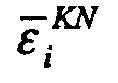
    removing guard intervals from the received signal;
    estimating channels for N number of sub carriers using a multi-carrier transmission symbol from which the guard interval has been removed; and
    interpolating (K-1) number of estimated channel values between the adjacent estimated channel values and obtaining estimated channel values for K · N number of sub carriers corresponding to said plurality of multi-carrier transmission symbols.
  12. A channel-estimation method in a multi-carrier receiving apparatus that receives and demodulates a signal to which a guard interval has been attached for every group of a plurality of (= K number of) multi-carrier transmission symbols comprising steps of:
    removing guard intervals from the received signal;
    estimating channels for N number of sub carriers using a multi-carrier transmission symbol from which the guard interval has been removed;
    performing N-point inverse-Fourier-transformation processing on the estimated channel values for N number of sub carriers and creating a delay profile that indicates the multi-path receiving levels;
    making receiving levels that exceed the guard-interval period Gl of that delay profile zero; and
    performing K · N-point Fourier-transformation processing on the delay profile that has been made zero to estimate channels for K · N number of sub carriers that correspond to said plurality of multi-carrier transmission symbols.
  13. A multi-carrier receiving apparatus in a multi-carrier communication system that receives and demodulates a signal to which a guard interval has been attached for every group of a plurality of (= K number of) multi-carrier transmission symbols comprising:
    a guard-interval-removal unit that removes guard intervals from a received signal;
    a Fourier-transformation unit that performs Fourier-transformation processing together for every group of a plurality of multi-carrier transmission symbols from which the guard intervals has been removed;
    a channel-estimation/compensation unit that estimates channels for sub carriers that correspond to the plurality of multi-carrier transmission symbols and performs channel compensation based on the channel-estimation results;
    an inverse-Fourier-transformation unit that performs inverse-Fourier-transformation processing together on the plurality of channel-compensated multi-carrier transmission symbols;
    a Fourier-transformation unit that performs Fourier-transformation processing on the inverse-Fourier-transformation results for each multi-carrier transmission symbol; and
    a demodulation unit that demodulates the transmission data based on the Fourier-transformation results.
  14. A multi-carrier receiving apparatus in a multi-carrier communication system that receives and demodulates a signal to which a guard interval has been attached for every group of a plurality of (= K number of) multi-carrier transmission symbols comprising:
    a guard-interval-removal unit that removes guard intervals from a received signal;
    a Fourier-transformation unit that performs Fourier-transformation processing together for every group of a plurality of multi-carrier transmission symbols from which the guard interval has been removed;
    a channel-estimation/compensation unit that estimates channels for sub carriers that correspond to the plurality of multi-carrier transmission symbols and performs channel compensation based on the channel-estimation results;
    a processing unit that performs inverse-Fourier-transformation processing together on the plurality of channel-compensated multi-carrier transmission symbols, as well as performs Fourier-transformation processing on the inverse-Fourier-transformation results for each multi-carrier transmission symbol; and
    a demodulation unit that demodulates the transmission data based on the Fourier-transformation results.
  15. A multi-carrier receiving apparatus in a multi-carrier communication system that receives and demodulates a signal to which a guard interval has been attached for every group of a plurality of multi-carrier transmission symbols comprising:
    a guard-interval-removal unit that removes guard intervals from a received signal;
    a processing unit that performs Fourier-transformation processing together for every group of a plurality of multi-carrier transmission symbols from which the guard interval has been removed, estimates channels for sub carriers that correspond to the plurality of multi-carrier transmission symbols and performs channel compensation based on the channel-estimation results, performs inverse-Fourier-transformation processing together on the plurality of channel-compensated multi-carrier transmission symbols, and performs Fourier-transformation processing on the inverse-Fourier-transformation results for each multi-carrier transmission symbol; and
    a demodulation unit that demodulates the transmission data based on the Fourier-transformation results.
  16. The multi-carrier receiving apparatus of claim 13 or claim 14 wherein
    said channel-estimation/compensation unit comprises:
    means for estimating channels for N number of sub carriers using a multi-carrier transmission symbol from which the guard interval has been removed; and
    means for interpolating (K-1) number of estimated channel values between the adjacent estimated channel values and obtaining estimated channel values for K · N number of sub carriers that correspond to said plurality of multi-carrier transmission symbols.
  17. The multi-carrier receiving apparatus of claim 13 or claim 14 wherein
    said channel-estimation/compensation unit comprises:
    means for estimating channels for N number of sub carriers using a multi-carrier transmission symbol from which the guard interval has been removed;
    means for performing N-point inverse-Fourier-transformation processing on the estimated channel values for N number of sub carriers and creating a delay profile that indicates the multi-path receiving levels;
    means for making the receiving level of paths that exceed the guard-interval period Gl of the delay profile zero; and
    means for performing K · N-point Fourier-transformation processing on the delay profile that has been made zero to estimate channels for K · N number of sub carriers that correspond to said plurality of multi-carrier transmission symbols.
  18. The multi-carrier receiving apparatus of any one of the claims 13 to 15 wherein said multi-carrier communication system is an 0FDM communication system.
  19. The multi-carrier receiving apparatus of any one of the claims 13 to 15 wherein said multi-carrier communication system is a multi-carrier. CDMA communication system.
  20. A channel-estimation apparatus in a multi-carrier receiving apparatus that receives and demodulates a signal to which a guard interval has been attached for every group of a plurality of (= K number of) multi-carrier transmission symbols comprising:
    means for removing guard intervals from a received signal;
    means for estimating channels for N number of sub carriers using a multi-carrier transmission symbol from which the guard interval has been removed; and
    means for interpolating (K-1) number of estimated channel values between the adjacent estimated channel values and obtaining estimated channel values for K · N number of sub carriers that correspond to said plurality of multi-carrier transmission symbols.
  21. A channel-estimation apparatus in a multi-carrier receiving apparatus that receives and demodulates a signal to which a guard interval has been attached for every group of a plurality of (= K number of) multi-carrier transmission symbols comprising:
    means for removing guard intervals from a received signal;
    means for estimating channels for N number of sub carriers using a multi-carrier transmission symbol from which the guard interval has been removed;
    means for performing N-point inverse-Fourier-transformation processing on the estimated channel values for N number of sub carriers and creating a delay profile that indicates the multi-path receiving levels;
    means for making the receiving level of paths that exceed the guard-interval period Gl of the delay profile zero; and
    means for performing K · N-point Fourier-transformation processing on the delay profile that has been made zero to estimate channels for K · N number of sub carriers that correspond to said plurality of multi-carrier transmission symbols.
EP04747493A 2004-07-14 2004-07-14 Multicarrier receiving method and multicarrier receiving apparatus Withdrawn EP1768287A1 (en)

Applications Claiming Priority (1)

Application Number Priority Date Filing Date Title
PCT/JP2004/010027 WO2006006238A1 (en) 2004-07-14 2004-07-14 Multicarrier receiving method and multicarrier receiving apparatus

Publications (1)

Publication Number Publication Date
EP1768287A1 true EP1768287A1 (en) 2007-03-28

Family

ID=35783604

Family Applications (1)

Application Number Title Priority Date Filing Date
EP04747493A Withdrawn EP1768287A1 (en) 2004-07-14 2004-07-14 Multicarrier receiving method and multicarrier receiving apparatus

Country Status (4)

Country Link
US (1) US20070133393A1 (en)
EP (1) EP1768287A1 (en)
JP (1) JPWO2006006238A1 (en)
WO (1) WO2006006238A1 (en)

Families Citing this family (9)

* Cited by examiner, † Cited by third party
Publication number Priority date Publication date Assignee Title
US7319690B2 (en) * 2003-08-08 2008-01-15 Nortel Networks Limited Communication signal equalization systems and methods
JP5024934B2 (en) * 2005-01-17 2012-09-12 シャープ株式会社 Wireless communication device
CN101438523A (en) * 2006-06-23 2009-05-20 松下电器产业株式会社 Wireless transmitting device, wireless receiving device and pilot generation method
US20080031220A1 (en) * 2006-08-03 2008-02-07 Qualcomm Incorporated Ofdm control signaling in the presence of timing asynchronization in a peer-to-peer network
KR100884385B1 (en) * 2007-08-31 2009-02-17 한국전자통신연구원 Signal transmission apparatus and method thereof, inverse fast Fourier inverter
US9762414B2 (en) * 2009-02-04 2017-09-12 Acorn Technologies, Inc. Least squares channel identification for OFDM Systems
JP5410812B2 (en) * 2009-03-31 2014-02-05 三星電子株式会社 Wireless communication apparatus, wireless communication system, and direct wave reception timing detection method
JP5707202B2 (en) * 2011-03-29 2015-04-22 パナソニック株式会社 Receiver
EP3997811A1 (en) * 2019-07-11 2022-05-18 Signify Holding B.V. A modulator for generating an orthogonal frequency division multiplexing, ofdm, signal

Family Cites Families (6)

* Cited by examiner, † Cited by third party
Publication number Priority date Publication date Assignee Title
US5886749A (en) * 1996-12-13 1999-03-23 Cable Television Laboratories, Inc. Demodulation using a time domain guard interval with an overlapped transform
JP3185874B2 (en) * 1998-07-21 2001-07-11 日本電気株式会社 Wireless communication system
JP3250728B2 (en) * 1998-11-19 2002-01-28 日本電気株式会社 Equalizer
US6912258B2 (en) * 2000-07-07 2005-06-28 Koninklijke Philips Electtronics N.V. Frequency-domain equalizer for terrestrial digital TV reception
WO2002067527A2 (en) * 2001-02-22 2002-08-29 Koninklijke Philips Electronics N.V. Multicarrier equalisation using multiplication by a leakage matrix
JP4298320B2 (en) * 2002-11-08 2009-07-15 富士通株式会社 Receiver for OFDM transmission system

Non-Patent Citations (1)

* Cited by examiner, † Cited by third party
Title
See references of WO2006006238A1 *

Also Published As

Publication number Publication date
US20070133393A1 (en) 2007-06-14
WO2006006238A1 (en) 2006-01-19
JPWO2006006238A1 (en) 2008-04-24

Similar Documents

Publication Publication Date Title
EP1861972B1 (en) Channel estimation optimization
EP1755301B1 (en) Guard interval setting method and apparatus in OFDM communication
US8488690B2 (en) Channel estimation
EP2605463B1 (en) Propagation path estimation method and apparatus
Park et al. Iterative receiver for joint detection and channel estimation in OFDM systems under mobile radio channels
US7952990B1 (en) Low complexity channel estimation for orthogonal frequency division modulation systems
US8050336B2 (en) Frequency domain equalization method and apparatus for a single carrier receiver
US8223862B2 (en) OFDM inter-carrier interference cancellation method
EP2192735A1 (en) Receiving apparatus and method for receiving signals in a wireless communication system with improved equalization performance
KR20070095309A (en) Delay-limited Channel Estimation for Multicarrier Systems
KR100749447B1 (en) method and apparatus for estimating timing error and frequency offset of HPI system
WO2010143532A1 (en) Receiving apparatus and receiving method
KR100973585B1 (en) Method and apparatus for estimating timing error and frequency offset in MIO mobile communication system
CN102045285A (en) Channel estimation method and device and communication system
JP2005192109A (en) Propagation path estimator for ofdm radio communication system, and receiver using the same
EP1768287A1 (en) Multicarrier receiving method and multicarrier receiving apparatus
Khan et al. LS estimator: Performance analysis for block-type and comb-type channel estimation in OFDM system
US7450490B2 (en) Channel estimation using the guard interval of a multicarrier signal
JPWO2007020943A1 (en) OFDM communication method
EP1928136A2 (en) Channel estimate optimization for multiple transmit modes
KR20060072096A (en) Method and apparatus for calculating ELL in orthogonal frequency division multiplexing communication system using linear equalizer
KR100575979B1 (en) Fast fading channel estimation apparatus and method in orthogonal frequency multiplexing mobile communication system
Smirani et al. An uplink LTE-A channel estimation method based On connexionist system
Sohl et al. Semiblind channel estimation for IFDMA in case of channels with large delay spreads
Ehichioya et al. Performance comparison of OFDM and DSSS on aeronautical channels

Legal Events

Date Code Title Description
PUAI Public reference made under article 153(3) epc to a published international application that has entered the european phase

Free format text: ORIGINAL CODE: 0009012

17P Request for examination filed

Effective date: 20070104

AK Designated contracting states

Kind code of ref document: A1

Designated state(s): DE FR GB

DAX Request for extension of the european patent (deleted)
RBV Designated contracting states (corrected)

Designated state(s): DE FR GB

STAA Information on the status of an ep patent application or granted ep patent

Free format text: STATUS: THE APPLICATION HAS BEEN WITHDRAWN

18W Application withdrawn

Effective date: 20090724