EP1768250A2 - Angular position detection for an electric motor - Google Patents
Angular position detection for an electric motor Download PDFInfo
- Publication number
- EP1768250A2 EP1768250A2 EP06118945A EP06118945A EP1768250A2 EP 1768250 A2 EP1768250 A2 EP 1768250A2 EP 06118945 A EP06118945 A EP 06118945A EP 06118945 A EP06118945 A EP 06118945A EP 1768250 A2 EP1768250 A2 EP 1768250A2
- Authority
- EP
- European Patent Office
- Prior art keywords
- motor
- estimated
- signal
- difference
- voltage
- Prior art date
- Legal status (The legal status is an assumption and is not a legal conclusion. Google has not performed a legal analysis and makes no representation as to the accuracy of the status listed.)
- Withdrawn
Links
Images
Classifications
-
- H—ELECTRICITY
- H02—GENERATION; CONVERSION OR DISTRIBUTION OF ELECTRIC POWER
- H02P—CONTROL OR REGULATION OF ELECTRIC MOTORS, ELECTRIC GENERATORS OR DYNAMO-ELECTRIC CONVERTERS; CONTROLLING TRANSFORMERS, REACTORS OR CHOKE COILS
- H02P6/00—Arrangements for controlling synchronous motors or other dynamo-electric motors using electronic commutation dependent on the rotor position; Electronic commutators therefor
- H02P6/14—Electronic commutators
- H02P6/16—Circuit arrangements for detecting position
- H02P6/18—Circuit arrangements for detecting position without separate position detecting elements
-
- H—ELECTRICITY
- H02—GENERATION; CONVERSION OR DISTRIBUTION OF ELECTRIC POWER
- H02P—CONTROL OR REGULATION OF ELECTRIC MOTORS, ELECTRIC GENERATORS OR DYNAMO-ELECTRIC CONVERTERS; CONTROLLING TRANSFORMERS, REACTORS OR CHOKE COILS
- H02P6/00—Arrangements for controlling synchronous motors or other dynamo-electric motors using electronic commutation dependent on the rotor position; Electronic commutators therefor
- H02P6/007—Arrangements for controlling synchronous motors or other dynamo-electric motors using electronic commutation dependent on the rotor position; Electronic commutators therefor wherein the position is detected using the ripple of the current caused by the commutation
-
- H—ELECTRICITY
- H02—GENERATION; CONVERSION OR DISTRIBUTION OF ELECTRIC POWER
- H02P—CONTROL OR REGULATION OF ELECTRIC MOTORS, ELECTRIC GENERATORS OR DYNAMO-ELECTRIC CONVERTERS; CONTROLLING TRANSFORMERS, REACTORS OR CHOKE COILS
- H02P6/00—Arrangements for controlling synchronous motors or other dynamo-electric motors using electronic commutation dependent on the rotor position; Electronic commutators therefor
- H02P6/34—Modelling or simulation for control purposes
-
- H—ELECTRICITY
- H02—GENERATION; CONVERSION OR DISTRIBUTION OF ELECTRIC POWER
- H02P—CONTROL OR REGULATION OF ELECTRIC MOTORS, ELECTRIC GENERATORS OR DYNAMO-ELECTRIC CONVERTERS; CONTROLLING TRANSFORMERS, REACTORS OR CHOKE COILS
- H02P7/00—Arrangements for regulating or controlling the speed or torque of electric DC motors
- H02P7/0094—Arrangements for regulating or controlling the speed or torque of electric DC motors wherein the position is detected using the ripple of the current caused by the commutator
-
- H—ELECTRICITY
- H02—GENERATION; CONVERSION OR DISTRIBUTION OF ELECTRIC POWER
- H02P—CONTROL OR REGULATION OF ELECTRIC MOTORS, ELECTRIC GENERATORS OR DYNAMO-ELECTRIC CONVERTERS; CONTROLLING TRANSFORMERS, REACTORS OR CHOKE COILS
- H02P2203/00—Indexing scheme relating to controlling arrangements characterised by the means for detecting the position of the rotor
- H02P2203/05—Determination of the rotor position by using two different methods and/or motor models
Definitions
- the present invention relates to a method and apparatus for determining an estimation error of an estimated motor rotation angle of an electric motor showing a periodic modulation of a motor current signal and / or a motor voltage signal in dependence on the motor rotation angle.
- Hall sensors are generally used to determine the position of mechanically commutated DC motors. Other methods are based on counting the ripple produced by the mechanical commutation process in the motor current signal. Such ripple counter methods are eg in the DE 100 28 033 , the DE 100 28 035 to DE 100 28 041 and in the US 20030111996 described. Here, the commutation ripple are separated by filtering (high pass, low pass, bandpass) before the actual count as possible from the current signal.
- a method which determines the engine speed and therefrom the motor or actuator position with the aid of an engine state model, a ripple detector and a downstream evaluation unit.
- the speed is determined here from the time interval of the detected commutation and with compared the estimated based on the engine state model speed.
- the evaluation unit determines the respectively more likely speed value and from the speed value by integration over the measuring time, the rotation angle.
- From the DE 199 25 327 A1 is a method for electronically monitoring and controlling a process for adjusting moving parts, in particular of windows and sunroofs of a motor vehicle, to ensure an anti-jamming known. This comprises at least the following steps: supplying process-specific input and output variables to a recognition device, finding and optimizing typical process variables of a model stored in the recognition device and describing the process, evaluating the typical parameters by comparison with data stored in the recognition device Process variables, determining a correction variable for the process as a function of the comparison, and influencing the process by supplying the determined correction quantity to the process.
- observers in particular state observers of the Luenberger type or Kalman filters, are known in control engineering, with whom the state variables of a dynamic system can be estimated model-based.
- the rotational angular position of an electric motor which shows a periodic modulation of a motor current signal and / or a motor voltage signal as a function of the motor rotation angle, based on measured values for the motor current signal, ie an armature current, and / or the motor voltage signal , ie a terminal voltage to determine.
- This should be the Uniqueness range of the rotation angle preferably extend over many engine revolutions.
- the inventive method for determining an estimation error of an estimated motor rotation angle of an electric motor which shows a periodic modulation of a motor current signal and / or a motor voltage signal, ie a power supply signal of the motor, in dependence on the motor rotation angle is characterized by a comparison of the estimated motor rotation angle with a phase angle of the periodic modulation of the motor current signal and / or the motor voltage signal.
- the inventive device for determining an estimation error of an estimated motor rotation angle of an electric motor which shows a periodic modulation of a motor current signal and / or a motor voltage signal in dependence on the motor rotation angle, is accordingly by a comparator unit for comparing the estimated motor rotation angle with a phase position of the periodic modulation of the motor current signal and / or the motor voltage signal.
- the motor rotation angle is calculated by integrating the motor rotation frequency or speed. This creates an integration error. Smaller errors in the engine speed result after integration over long time intervals very large errors in the absolute rotational angle position. This error does not occur in the method according to the invention, since the angular position directly, ie, not by integration of the Motor rotational frequency, determined and then verified by comparison.
- the estimated motor rotation angle according to the invention is preferably determined by means of a motor model from the motor current signal and / or the motor voltage signal.
- the motor model is further preferably integrated into an observer and is optimized via its observer function.
- the comparison of the estimated motor rotation angle with the phase position of the periodic modulation of the motor signal and / or the motor voltage signal preferably takes place via an evaluation of a difference between the motor current and a current estimated by the motor model and / or an evaluation of a difference between the motor voltage and a through the engine model estimated voltage.
- the device according to the invention preferably has a subtractor unit for forming this difference (s).
- the phase position of the periodic modulation of the motor current signal and / or of the motor voltage signal is determined by at a point in time at which a current ripple signal resulting from the difference of the motor current with the motor current estimated by the motor model and / or or at which a voltage ripple signal resulting from the difference of the motor voltage with the motor voltage estimated by the motor model is detected, an angular difference between the estimated motor rotation angle and a target angle expected at the commutation time is evaluated.
- the device according to the invention preferably has a plausibility unit for determining these times.
- the phase position of the periodic modulation of the motor current signal and / or the motor voltage signal is determined by an angle difference between a current model for the commutation ripple in Motorstromsginal and / or in the motor voltage signal, the is determined on the basis of the estimated motor rotation angle, generated signal and a resulting from the difference of the motor current with the motor model estimated by the motor current Stromripplesignal and / or by the difference of the motor voltage with the motor model estimated by the motor voltage voltage ripple signal is evaluated.
- the device according to the invention preferably has an angle difference evaluation unit for evaluating the angular difference.
- the angular difference is preferably converted from a small unambiguity range [0, 2 ⁇ / a], with a as the number of ripples occurring in the respective signal per motor revolution, to a greater uniqueness range.
- This larger uniqueness range covers the required number of engine revolutions for the respective application.
- the device according to the invention preferably has an unwrapping unit.
- the difference between the motor current and the motor current estimated by the motor model and / or the difference between the motor voltage and the motor voltage estimated by the motor model is preferably adaptively bandpass filtered before it is evaluated, the bandpass filtering being performed with an adaptively adjustable center frequency. Further preferably, the adjustment of the center frequency is dependent on an estimated by the engine model rotational frequency of the electric motor.
- the device according to the invention preferably has an adaptive bandpass filter.
- parameters of the engine model are preferably estimated from the motor current signal and / or the motor voltage signal.
- the device according to the invention preferably has a parameter estimation unit.
- a rotational frequency of the electric motor is estimated from an unfiltered difference or a filtered difference between the motor current and a current estimated by the motor model and / or between the motor voltage and a voltage estimated by the motor model.
- the method according to the invention and the device according to the invention are preferably integrated in seat control devices for car seats or in control devices for sunroofs, window regulators or flap actuators.
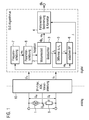
- FIG. 1 shows the basic structure of a preferred embodiment of the system according to the invention.
- the system is based on the measurement of the voltage drop across the motor (terminal voltage) and the current flowing in the motor (armature current).
- terminal voltage terminal voltage
- armature current current flowing in the motor
- the terminal voltage U M and the voltage U R dropping across a shunt resistor 9 connected in series with the motor 1 are measured on the motor 1.
- the supply voltage for the motor U batt is above the series circuit of motor 1 and shunt resistor 9 at.
- the analog terminal voltage U M and the voltage drop across the shunt resistor 9 U R are amplified in a detection unit 10, low-pass filtered (anti-aliasing filter), digitized (A / D conversion) and in a preprocessing in the digitized signals terminal voltage To implemented as well as armature current Im.
- the invention System can be realized for example by a ⁇ C or a suitable specific hardware (FPGA, ASIC, etc.), as well as a discrete structure.
- FPGA field-programmable gate array
- FIG. 1 the wiring of the motor when using only one shunt resistor 9 without the necessary for the control of the motor 1 switch (relay, transistor, etc.) is exemplified.
- the preferred embodiment of the system according to the invention for determining the sought motor rotation angle ⁇ e consists essentially of an observer 3 and a error angle determination 4.
- the observer 3 includes a motor model 2 whose parameters, eg inductance, resistance, motor constant, friction and Transmission elasticities, based on the digitized motor voltage U m and the digitized motor current I m and possibly an estimated angular frequency ⁇ e are determined by a parameter estimation 8.
- the states of the motor 1, eg current I b , rotational frequency ⁇ b and the rotational angle ⁇ b and possibly also the load torque M L and other application-specific states are estimated.
- the observer 3 can also be operated as a pure simulator, ie, only with the motor model 2 without the correction function of the observer 3 activated. Since such an estimate of the states of the engine and other application-specific states generally in the literature, eg
- One or more of the state variables digitized (measured) motor current I m , estimated frequency ⁇ e and estimated angle ⁇ e can be used as feedback variables for the observer.
- the commutation processes are not shown in the engine model 2 or the observer 3 is designed so that they are not included in the estimated current I b as possible.
- the difference signal I d can now be subsequently filtered by an adaptive bandpass 6 with the bandwidth B that can be adjusted in its center frequency ⁇ m .
- a is equal to the number of ripple occurring per motor revolution in the motor current signal I M and in the digitized motor current signal I m .
- the unfiltered current difference signal I d is now both a frequency estimation made by a frequency estimation unit 7, which in turn serves as an input signal for the parameter estimate performed by the parameter estimation unit 8 parameter estimation, as well an error angle determination is performed in the comparator unit 4.
- the phase position of the current ripple caused by the mechanical commutation process is evaluated.
- the comparator unit then outputs the corrected estimated angle ⁇ e .
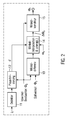
- FIG. 2 shows a first preferred embodiment of the comparator unit 4.
- the current ripple caused by the commutation process is detected in the filtered difference signal I f or alternatively directly in the difference signal I d (not shown) and made plausible on the basis of the motor rotation angle ⁇ b estimated by the observer 3. That is, in dependence on the estimated by the observer motor rotation angle ⁇ b in a plausibility unit 12 by a detector 11th generated detection signal either suppressed or enabled.
- the detection signal d assumes the value 1, if no ripplesignal is detected, it has the value 0.
- the plausibility is the robustness of the method against interference and the occurrence of multiple ripples per Commutation increased. However, the plausibility check is not absolutely necessary when using the band-pass filtered difference signal I f .
- an angle difference between the observer-estimated angle ⁇ b and the target angle ⁇ s is generated by means of an angle difference generating unit 13.
- the nominal angle ⁇ s is the theoretically expected motor angle at the times of the commutation processes.
- the angular difference is to be determined at a defined phase position in the current ripple signal. However, since the angular difference here exists only at the discrete measured-value sampling instants, it is subsequently interpolated in an angle interpolation and unwrapping unit 14. With the help of the angle interpolation, the angular difference, which is present in each case in the presence of a defined phase position in the current ripple signal (eg in zero crossing or maximum), is calculated.
- the angle difference determined via the phase comparison and the angular interpolation is present as a modulo 2 ⁇ / a value (uniqueness range: [0, 2 ⁇ / a]), this must still be converted to the larger value range or uniqueness range required by the respective application.
- the function "unwrap" known per se from the Matlab program, for example, is used. used.
- the unique angle error ⁇ b of the observer angle ⁇ b then present is now used by an angle correction unit 15 for correcting the observer angle ⁇ b .
- the result is the estimated and corrected motor rotation angle ⁇ e .
- the function "Unwrap" can also be applied after the angle correction (not shown).
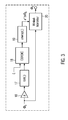
- FIG. 3 shows a second preferred embodiment of the comparator unit 4.
- the angle ⁇ b estimated by the observer 3 is used to generate a cosinusoidal oscillation.
- This cosinusoidal oscillation generated by an amplification of the estimated angle ⁇ b with a gain factor a in an amplifier 16 and a subsequent signal processing in a signal generator 17 is thus a signal model for the commutation-related ripple in the motor current signal I M or in the digitized motor current signal I m .
- the phase angle of this signal is compared with the phase angle of the filtered or unfiltered current difference signal I f or I d . This is done in an angle difference evaluation unit 18, for example using the CORDIC method.
- the angle difference a * ⁇ b determined via the phase comparison is present as a modulo 2n value, it must still be converted to a uniqueness range greater than [0, 2 ⁇ ], for which an unwracking function 19 is again used in an unwrapping unit 19 the same known Matlab function corresponds.
- the phase difference ⁇ b is then used in an angle correction unit 20 for correcting the erroneous estimated value for the estimated motor rotation angle ⁇ b .
- other known methods are possible instead of the CORDIC method, for example the for the implementation of phase-locked loop (PLL) circuits used method.
- PLL phase-locked loop
- the use of the "unwrap function" is also possible after the angle correction (not shown here).
- the inventively proposed system of a sensorless determination of the motor rotation angle can be used not only in DC motors, but also in any other engines that show a comparable periodic modulation of the current or voltage signal as a function of motor rotation angle.
Abstract
Description
Die vorliegende Erfindung betrifft ein Verfahren und eine Vorrichtung zur Bestimmung eines Schätzfehlers eines geschätzten Motordrehwinkels eines Elektromotors, der eine periodische Modulation eines Motorstromsignals und/oder eines Motorspannungssignals in Abhängigkeit von dem Motordrehwinkel zeigt.The present invention relates to a method and apparatus for determining an estimation error of an estimated motor rotation angle of an electric motor showing a periodic modulation of a motor current signal and / or a motor voltage signal in dependence on the motor rotation angle.
Zur Positionsbestimmung von mechanisch kommutierten Gleichstrommotoren werden in der Regel Hallsensoren eingesetzt. Andere Verfahren basieren auf einer Zählung der durch den mechanischen Kommutierungsvorgang im Motorstromsignal entstehenden Ripple. Solche Ripple-Counter-Verfahren sind z.B. in der
In der
Aus der
Desweiteren sind in der Regelungstechnik Beobachter, insbesondere Zustandsbeobachter vom Luenberger-Typ oder Kalman-Filter, bekannt, mit denen die Zustandsgrößen eines dynamischen Systems modellbasiert geschätzt werden können.Furthermore, observers, in particular state observers of the Luenberger type or Kalman filters, are known in control engineering, with whom the state variables of a dynamic system can be estimated model-based.
Es ist daher die der vorliegenden Erfindung zugrunde liegenden Aufgabe, die Drehwinkelposition eines Elektromotors, der eine periodische Modulation eines Motorstromsignals und/oder eines Motorspannungssignals in Abhängigkeit von dem Motordrehwinkel zeigt, anhand von Messwerten für das Motorstromsignal, d.h. einem Ankerstrom, und/oder das Motorspannungssignal, d.h. einer Klemmenspannung, zu bestimmen. Hierbei soll sich der Eindeutigkeitsbereich des Drehwinkels vorzugsweise über viele Motorumdrehungen erstrecken.It is therefore the object underlying the present invention, the rotational angular position of an electric motor, which shows a periodic modulation of a motor current signal and / or a motor voltage signal as a function of the motor rotation angle, based on measured values for the motor current signal, ie an armature current, and / or the motor voltage signal , ie a terminal voltage to determine. This should be the Uniqueness range of the rotation angle preferably extend over many engine revolutions.
Das erfindungsgemäße Verfahren zur Bestimmung eines Schätzfehlers eines geschätzten Motordrehwinkels eines Elektromotors, der eine periodische Modulation eines Motorstromsignals und/oder eines Motorspannungssignals, also eines Energieversorgungssignals des Motors, in Abhängigkeit von dem Motordrehwinkel zeigt, ist gekennzeichnet durch einen Vergleich des geschätzten Motordrehwinkels mit einer Phasenlage der periodischen Modulation des Motorstromsignals und/oder des Motorspannungssignals.The inventive method for determining an estimation error of an estimated motor rotation angle of an electric motor, which shows a periodic modulation of a motor current signal and / or a motor voltage signal, ie a power supply signal of the motor, in dependence on the motor rotation angle is characterized by a comparison of the estimated motor rotation angle with a phase angle of the periodic modulation of the motor current signal and / or the motor voltage signal.
Die erfindungsgemäße Vorrichtung zur Bestimmung eines Schätzfehlers eines geschätzten Motordrehwinkels eines Elektromotors, der eine periodische Modulation eines Motorstromsignals und/oder eines Motorspannungssignals in Abhängigkeit von dem Motordrehwinkel zeigt, ist entsprechend durch eine Vergleichereinheit zum Vergleich des geschätzten Motordrehwinkels mit einer Phasenlage der periodischen Modulation des Motorstromsignals und/oder des Motorspannungssignals gekennzeichnet.The inventive device for determining an estimation error of an estimated motor rotation angle of an electric motor, which shows a periodic modulation of a motor current signal and / or a motor voltage signal in dependence on the motor rotation angle, is accordingly by a comparator unit for comparing the estimated motor rotation angle with a phase position of the periodic modulation of the motor current signal and / or the motor voltage signal.
In bekannten Verfahren wird, wie zuvor beschrieben, der Motordrehwinkel durch Integration der Motordrehfrequenz bzw. Drehzahl berechnet. Dadurch entsteht ein Integrationsfehler. Kleinere Fehler in der Motordrehfrequenz ergeben nach einer Integration über längere Zeitintervalle sehr große Fehler in der absoluten Drehwinkelposition. Dieser Fehler tritt im erfindungsgemäßen Verfahren nicht auf, da hier die Drehwinkelposition direkt, d.h., nicht durch Integration der Motordrehfrequenz, bestimmt und anschließend durch Vergleich verifiziert wird.In known methods, as described above, the motor rotation angle is calculated by integrating the motor rotation frequency or speed. This creates an integration error. Smaller errors in the engine speed result after integration over long time intervals very large errors in the absolute rotational angle position. This error does not occur in the method according to the invention, since the angular position directly, ie, not by integration of the Motor rotational frequency, determined and then verified by comparison.
Weiter sind erfindungsgemäß für die Drehwinkelbestimmung keine zusätzlichen Sensoren (z.B. Hallsensoren) einschließlich zu deren Anschluss benötigter Kabel, Stecker und Hardware für die Signalauswertung notwendig. Dadurch wird erfindungsgemäß eine Reduktion der Systemkosten ermöglicht.Furthermore, according to the invention, no additional sensors (for example Hall sensors), including cables, plugs and hardware required for signal evaluation, are required for determining the angle of rotation. As a result, a reduction of the system costs is made possible according to the invention.
Mit dem erfindungsgemäßen Verfahren und der erfindungsgemäßen Vorrichtung kann eine sehr hohe Stabilität und Robustheit erreicht werden, dies auch im Vergleich zu derzeit vorrangig eingesetzten Verfahren und Vorrichtungen mit Hallsensorik. Bei einer ausreichend hohen Genauigkeit des Motormodells ergibt sich im Gegensatz zu dem in der
Wie zuvor schon erwähnt, wird der geschätzte Motordrehwinkel nach der Erfindung vorzugsweise mittels eines Motormodells aus dem Motorstromsignal und/oder dem Motorspannungssignal ermittelt. Das Motormodell ist weiter vorzugsweise in einen Beobachter integriert und wird über dessen Beobachterfunktion optimiert.As already mentioned above, the estimated motor rotation angle according to the invention is preferably determined by means of a motor model from the motor current signal and / or the motor voltage signal. The motor model is further preferably integrated into an observer and is optimized via its observer function.
Erfindungsgemäß erfolgt der Vergleich des geschätzten Motordrehwinkels mit der Phasenlage der periodischen Modulation des Motorsignals und/oder des Motorspannungssignals vorzugsweise über eine Auswertung einer Differenz zwischen dem Motorstrom und einem durch das Motormodell geschätzten Strom und/oder über eine Auswertung einer Differenz zwischen der Motorspannung und einer durch das Motormodell geschätzten Spannung. Hierzu weist die erfindungsgemäße Vorrichtung vorzugsweise eine Subtrahierereinheit zur Bildung dieser Differenz(en) auf.According to the invention, the comparison of the estimated motor rotation angle with the phase position of the periodic modulation of the motor signal and / or the motor voltage signal preferably takes place via an evaluation of a difference between the motor current and a current estimated by the motor model and / or an evaluation of a difference between the motor voltage and a through the engine model estimated voltage. For this purpose, the device according to the invention preferably has a subtractor unit for forming this difference (s).
In einer ersten bevorzugten Weiterbildung dieses Vergleichs über eine Auswertung einer Differenz wird die Phasenlage der periodischen Modulation des Motorstromsignals und/oder des Motorspannungssignals ermittelt, indem zu Zeitpunkten, an denen ein durch die Differenz des Motorstroms mit dem durch das Motormodell geschätzten Motorstrom entstehendes Stromripplesignal und/oder an denen ein durch die Differenz der Motorspannung mit der durch das Motormodell geschätzten Motorspannung entstehendes Spannungsripplesignal detektiert wird, eine Winkeldifferenz zwischen dem geschätzten Motordrehwinkel und einem zu dem Kommutierungszeitpunkt erwartetem Sollwinkel ausgewertet wird. Hierzu weist die erfindungsgemäße Vorrichtung vorzugsweise eine Plausibilisierungseinheit zur Bestimmung dieser Zeitpunkte auf.In a first preferred development of this comparison by means of an evaluation of a difference, the phase position of the periodic modulation of the motor current signal and / or of the motor voltage signal is determined by at a point in time at which a current ripple signal resulting from the difference of the motor current with the motor current estimated by the motor model and / or or at which a voltage ripple signal resulting from the difference of the motor voltage with the motor voltage estimated by the motor model is detected, an angular difference between the estimated motor rotation angle and a target angle expected at the commutation time is evaluated. For this purpose, the device according to the invention preferably has a plausibility unit for determining these times.
In einer alternativen zweiten bevorzugten Weiterbildung eines solchen Vergleichs über eine Auswertung einer Differenz wird die Phasenlage der periodischen Modulation des Motorstromsignals und/oder des Motorspannungssignals ermittelt, indem eine Winkeldifferenz zwischen einem durch ein Strommodell für den kommutierungsbedingten Ripple im Motorstromsginal und/oder im Motorspannungssignal, das anhand des geschätzten Motordrehwinkels bestimmt wird, erzeugten Signal und einem durch die Differenz des Motorstroms mit dem durch das Motormodell geschätzten Motorstrom entstehendes Stromripplesignal und/oder einem durch die Differenz der Motorspannung mit der durch das Motormodell geschätzten Motorspannung entstehendes Spannungsripplesignal ausgewertet wird. Hierzu weist die erfindungsgemäße Vorrichtung vorzugsweise eine Winkeldifferenz-Auswertungseinheit zur Auswertung der Winkeldifferenz auf.In an alternative second preferred development of such a comparison via an evaluation of a difference, the phase position of the periodic modulation of the motor current signal and / or the motor voltage signal is determined by an angle difference between a current model for the commutation ripple in Motorstromsginal and / or in the motor voltage signal, the is determined on the basis of the estimated motor rotation angle, generated signal and a resulting from the difference of the motor current with the motor model estimated by the motor current Stromripplesignal and / or by the difference of the motor voltage with the motor model estimated by the motor voltage voltage ripple signal is evaluated. For this purpose, the device according to the invention preferably has an angle difference evaluation unit for evaluating the angular difference.
In diesen beiden bevorzugten Weiterbildungen wird vorzugsweise die Winkeldifferenz aus einem kleinen Eindeutigkeitsbereich [0, 2π/a], mit a als Anzahl von pro Motorumdrehung auftretenden Ripplen im jeweiligen Signal, auf einen größeren Eindeutigkeitsbereich umgesetzt. Dieser größere Eindeutigkeitsbereich überdeckt die geforderte Anzahl von Motorumdrehungen für die jeweilige Anwendung. Hierzu weist die erfindungsgemäße Vorrichtung vorzugsweise eine Unwrap-Einheit auf.In these two preferred developments, the angular difference is preferably converted from a small unambiguity range [0, 2π / a], with a as the number of ripples occurring in the respective signal per motor revolution, to a greater uniqueness range. This larger uniqueness range covers the required number of engine revolutions for the respective application. For this purpose, the device according to the invention preferably has an unwrapping unit.
Erfindungsgemäß wird die Differenz zwischen dem Motorstrom und dem durch das Motormodell geschätzten Motorstrom und/oder die Differenz zwischen der Motorspannung und der durch das Motormodell geschätzten Motorspannung vorzugsweise adaptiv bandpassgefiltert, bevor diese ausgewertet wird, wobei die Bandpassfilterung mit einer adaptiv verstellbaren Mittenfrequenz erfolgt. Weiter vorzugsweise erfolgt die Verstellung der Mittenfrequenz abhängig von einer von dem Motormodell geschätzten Umdrehungsfrequenz des Elektromotors. Hierzu weist die erfindungsgemäße Vorrichtung vorzugsweise ein adaptives Bandpassfilter auf.According to the invention, the difference between the motor current and the motor current estimated by the motor model and / or the difference between the motor voltage and the motor voltage estimated by the motor model is preferably adaptively bandpass filtered before it is evaluated, the bandpass filtering being performed with an adaptively adjustable center frequency. Further preferably, the adjustment of the center frequency is dependent on an estimated by the engine model rotational frequency of the electric motor. For this purpose, the device according to the invention preferably has an adaptive bandpass filter.
Nach der Erfindung werden Parameter des Motormodells vorzugsweise anhand des Motorstromsignals und/oder des Motorspannungssignals geschätzt. Hierzu weist die erfindungsgemäße Vorrichtung vorzugsweise eine Parameter-Schätzeinheit auf.According to the invention, parameters of the engine model are preferably estimated from the motor current signal and / or the motor voltage signal. For this purpose, the device according to the invention preferably has a parameter estimation unit.
Nach der Erfindung wird eine Umdrehungsfrequenz des Elektromotors anhand einer ungefilterten Differenz oder einer über ein Bandpassfilter gefilterten Differenz zwischen dem Motorstrom und einem durch das Motormodell geschätzten Strom und/oder zwischen der Motorspannung und einer durch das Motormodell geschätzten Spannung geschätzt.According to the invention, a rotational frequency of the electric motor is estimated from an unfiltered difference or a filtered difference between the motor current and a current estimated by the motor model and / or between the motor voltage and a voltage estimated by the motor model.
Das erfindungsgemäße Verfahren und die erfindungsgemäße Vorrichtung sind vorzugsweise in Sitzsteuergeräten für Autositze oder in Steuergeräten für Schiebedächer, Fensterheber oder Klappensteller integriert.The method according to the invention and the device according to the invention are preferably integrated in seat control devices for car seats or in control devices for sunroofs, window regulators or flap actuators.
Weitere Vorteile der Erfindung ergeben sich aus der folgenden Zeichnungsbeschreibung. In den Zeichnungen sind Ausführungsbeispiele der Erfindung beispielhaft dargestellt. Die Zeichnungen, die Beschreibung und die Ansprüche enthalten zahlreiche Merkmale in Kombination oder als bevorzugtes Ausführungsbeispiel der Erfindung bezeichnet. Der Fachmann wird die Merkmale zweckmäßigerweise auch einzeln betrachten und/oder zur sinnvollen weiteren Kombination zusammenfassen.Further advantages of the invention will become apparent from the following description. Exemplary embodiments of the invention are shown in the drawings by way of example. The drawings, the description and the claims contain numerous features in combination or referred to as a preferred embodiment of the invention. The person skilled in the art will also consider the features individually and / or summarize the meaningful further combination.
Es zeigen:
- Figur 1
- einen grundsätzlichen Aufbau einer bevorzugten Ausführungsform der Vorrichtung des Verfahrens nach der Erfindung,
Figur 2- eine erste bevorzugte Ausführungsform einer erfindungsgemäßen Fehlerwinkelbestimmung und -korrektur, und
- Figur 3
- eine zweite bevorzugte Ausführungsform einer erfindungsgemäßen Fehlerwinkelbestimmung und -korrektur.
- FIG. 1
- a basic structure of a preferred embodiment of the device of the method according to the invention,
- FIG. 2
- a first preferred embodiment of error angle determination and correction according to the invention, and
- FIG. 3
- a second preferred embodiment of an error angle determination and correction according to the invention.
In Figur 1 ist der grundsätzliche Aufbau einer bevorzugten Ausführungsform des erfindungsgemäßen Systems dargestellt. Das System basiert auf der Messung der über den Motor abfallenden Spannung (Klemmenspannung) sowie des im Motor fließenden Stroms (Ankerstrom). Dazu werden am Motor 1 die Klemmenspannung UM und die über einen zum Motor 1 in Reihe geschalteten Shunt-Widerstand 9 abfallende Spannung UR gemessen. Die Versorgungsspannung für den Motor Ubatt liegt über der Reihenschaltung aus Motor 1 und Shunt-Widerstand 9 an. Die analoge Klemmenspannung UM und die über den Shunt-Widerstand 9 abfallende Spannung UR werden in einer Erfassungseinheit 10 verstärkt, tiefpassgefiltert (Anti-Aliasing-Filter), digitalisiert (A/D-Wandlung) und in einer Vorverarbeitung in die digitalisierten Signale Klemmenspannung Um sowie Ankerstrom Im umgesetzt.FIG. 1 shows the basic structure of a preferred embodiment of the system according to the invention. The system is based on the measurement of the voltage drop across the motor (terminal voltage) and the current flowing in the motor (armature current). For this purpose, the terminal voltage U M and the voltage U R dropping across a
Nachfolgend werden dann die digitalisierten Signale Klemmenspannung Um und Ankerstrom Im mit Hilfe des erfindungsgemäßen Systems ausgewertet und hierdurch der gesuchte Motordrehwinkel Φe bestimmt. Das erfindungsgemäße System kann z.B. durch ein µC oder eine geeignete spezifische Hardware (FPGA, ASIC, etc.), wie auch einen diskreten Aufbau realisiert werden. In Figur 1 ist beispielshaft die Beschaltung des Motors bei Nutzung nur eines Shunt-Widerstands 9 ohne den für die Ansteuerung des Motors 1 notwendigen Schalter (Relais, Transistor, etc.) dargestellt. Eine Beschaltung mit Hilfe von zwei, jeweils an der unteren und der oberen Motorklemme angebrachten mit dem Motor 1 in Reihe geschalteten Shunt-Widerständen (nicht dargestellt), ist ebenfalls möglich, jedoch nicht wesentlich für das erfindungsgemäße System.Subsequently, the digitized signals terminal voltage U m and armature current I m are then evaluated using the system according to the invention and thereby the desired motor rotation angle Φ e determined. The invention System can be realized for example by a μC or a suitable specific hardware (FPGA, ASIC, etc.), as well as a discrete structure. In Figure 1, the wiring of the motor when using only one
Die in der Figur 1 gezeigte bevorzugte Ausführungsform des erfindungsgemäßen Systems zur Bestimmung des gesuchten Motordrehwinkels Φe besteht im Wesentlichen aus einem Beobachter 3 und einer Fehlerwinkelbestimmung 4. Der Beobachter 3 beinhaltet ein Motormodell 2, dessen Parameter, z.B. Induktivität, Widerstand, Motorkonstante, Reibung und Getriebeelastizitäten, anhand der digitalisierten Motorspannung Um und des digitalisierten Motorstroms Im und ggf. einer geschätzten Kreisfrequenz ωe durch eine Parameterschätzung 8 ermittelt werden. Mit Hilfe des Beobachters 3 werden nun die Zustände des Motors 1, z.B. Strom Ib, Drehfrequenz ωb und der Drehwinkel Φb und ggf. auch das Lastmoment ML und weitere applikationsspezifische Zustände geschätzt. Bei ausreichend hoher Genauigkeit des Motormodells 2 bzw. der geschätzten Parameter sowie der Kenntnis aller Eingangsgrößen kann der Beobachter 3 auch als reiner Simulator, d.h., nur mit dem Motormodell 2 ohne aufgeschaltete Korrekturfunktion des Beobachters 3, betrieben werden. Da eine solche Schätzung der Zustände des Motors und weiterer applikationsspezifischer Zustände allgemein in der Fachliteratur, z.B.The preferred embodiment of the system according to the invention for determining the sought motor rotation angle φ e consists essentially of an observer 3 and a
Als Rückführgrößen für den Beobachter können hierbei eine oder mehrere der Zustandsgrößen digitalisierter (gemessener) Motorstrom Im, geschätzte Frequenz ωe und geschätzter Winkel Φe verwendet werden.One or more of the state variables digitized (measured) motor current I m , estimated frequency ω e and estimated angle φ e can be used as feedback variables for the observer.
Die Kommutierungsvorgänge sind dabei nicht im Motormodell 2 abgebildet bzw. der Beobachter 3 ist derart ausgelegt, dass diese in dem geschätzten Strom Ib möglichst nicht enthalten sind. Der mit Hilfe des Beobachters geschätzte Strom Ib wird in dieser Ausführungsform mittels einer Subtrahierereinheit 5 vom gemessenen digitaliserten Motorstrom Im abgezogen, wodurch eine Stromdifferenz Id = Im - Ib erhalten wird. Durch die Differenzbildung enthält man nun mit dem Differenzsignal Id näherungsweise unabhängig von äußeren Spannungsschwankungen der Versorgungsspannung Ubat das gewünschte kommutierungsbedingte Ripplesignal. Das Differenzsignal Id kann nun nachfolgend durch einen in seiner Mittenfrequenz ωm verstellbaren adaptiven Bandpass 6 mit der Bandbreite B gefiltert werden. Die Mittenfrequenz ωm des Bandpasses 6 wird vorzugsweise durch die vom Beobachter 3 geschätzte Frequenz ωb vorgegeben als ωm = a · ωb, wobei a gleich der Anzahl der pro Motorumdrehung auftretenden Ripple im Motorstromsignal IM bzw. im digitalisierten Motorstromsignal Im ist. Dadurch wird ein erheblicher Teil von Störungen, d.h., Schwankungen der Versorgungsspannung, Oberwellen, Digitalisierungsrauschen, etc., aus dem zu verarbeitenden Signal gefiltert. Durch die Bandpassfilterung wird somit die Detektionswahrscheinlichkeit des Ripplesignals bei schlechtem Signal-zu-Störsignal-Verhältnis erhöht und die Genauigkeit und Robustheit der nachfolgenden Winkelinterpolation und der Frequenzschätzung und damit des gesamten im erfindungsgemäßen System verwirklichten Verfahrens verbessert.The commutation processes are not shown in the
Mit Hilfe des gefilterten Stromdifferenzsignals If oder - alternativ bei Wegfall des Bandpassfilters 6 - des ungefilterten Stromdifferenzsignals Id wird nun sowohl eine Frequenzschätzung mittels einer Frequenzschätzungseinheit 7 vorgenommen, die wiederum als Eingabesignal für die mittels der Parameter-Schätzeinheit 8 durchgeführten Parameterschätzung dient, als auch eine Fehlerwinkelbestimmung in der Vergleichereinheit 4 durchgeführt. Mit Hilfe der Fehlerwinkelbestimmung soll der Fehler ΔΦb = Φb - Φ des durch den Beobachter geschätzten Motordrehwinkels Φb, d.h., die Abweichung zwischen dem durch das Motormodell 2 geschätzten Motordrehwinkel Φb, und dem tatsächlichen Motordrehwinkel Φ ermittelt und nachfolgend korrigiert werden. Dazu wird die Phasenlage der durch den mechanischen Kommutierungsvorgang hervorgerufene Stromripple ausgewertet. Die Vergleichereinheit gibt dann den korrigierten geschätzten Winkel Φe aus.With the aid of the filtered current difference signal I f or - alternatively when the bandpass filter 6 - the unfiltered current difference signal I d is now both a frequency estimation made by a frequency estimation unit 7, which in turn serves as an input signal for the parameter estimate performed by the parameter estimation unit 8 parameter estimation, as well an error angle determination is performed in the
Figur 2 zeigt eine erste bevorzugte Ausführungsform der Vergleichereinheit 4. Hier werden die durch den Kommutierungsvorgang hervorgerufenen Stromripple im gefilterten Differenzsignal If oder alternativ direkt im Differenzsignal Id (nicht dargestellt) detektiert und anhand des vom Beobachter 3 geschätzten Motordrehwinkels Φb plausibilisiert. D.h., in Abhängigkeit von dem vom Beobachter geschätzten Motordrehwinkel Φb wird in einer Plausibilisierungseinheit 12 ein von einem Detektor 11 erzeugtes Detektionssignal entweder unterdrückt oder ermöglicht. Zu dem Zeitpunkt, an denen die plausibilisierten Stromripple erkannt werden, nimmt das Detektionssignal d den Wert 1 an, wenn kein Ripplesignal erkannt wird, besitzt es den Wert 0. Durch die Plausibilisierung wird die Robustheit des Verfahrens gegenüber Störungen und dem Auftreten von mehreren Ripplen pro Kommutierungsvorgang erhöht. Die Plausibilisierung ist jedoch bei Verwendung des bandpassgefilterten Differenzsignals If nicht zwingend notwendig.FIG. 2 shows a first preferred embodiment of the
Zu den Zeitpunkten, an denen Ripplesignale detektiert werden, wird eine mittels einer Winkeldifferenz-Erzeugungseinheit 13 erzeugte Winkeldifferenz zwischen dem mit dem Beobachter geschätzten Winkel Φb und dem Sollwinkel Φs ausgewertet. Der Sollwinkel Φs ist der zu den Zeitpunkten der Kommutierungsvorgänge jeweils theoretisch erwartete Motorwinkel. Die Winkeldifferenz soll dabei bei einer definierten Phasenlage im Stromripplesignal ermittelt werden. Da die Winkeldifferenz hier jedoch nur zu den diskreten Messwerten-Abtastzeitpunkten vorliegt, wird diese nachfolgend in einer Winkelinterpolations- und Unwrap-Einheit 14 interpoliert. Mit Hilfe der Winkelinterpolation wird die Winkeldifferenz, die jeweils bei Vorhandensein einer definierten Phasenlage im Stromripplesignal (z.B. im Nulldurchgang oder Maximum) vorliegt, berechnet.At the times at which ripplesignals are detected, an angle difference between the observer-estimated angle φ b and the target angle φ s is generated by means of an angle
Da die über den Phasenvergleich und die Winkelinterpolation ermittelte Winkeldifferenz als Modulo 2π/a-Wert (Eindeutigkeitsbereich: [0, 2π/a]) vorliegt, muss diese noch auf den von der jeweiligen Anwendung benötigten größeren Werte- bzw. Eindeutigkeitsbereich umgesetzt werden. Hierzu wird in der Winkelinterpolations- und Unwrap-Einheit die an sich z.B. aus dem Programm Matlab bekannte Funktion "Unwrap" eingesetzt. Der dann vorliegenden eindeutige Winkelfehler ΔΦb des Beobachterwinkels Φb wird jetzt von einer Winkelkorrektureinheit 15 zur Korrektur des Beobachterwinkels Φb verwendet. Nach der Korrektur erhält man im Ergebnis den geschätzten und korrigierten Motordrehwinkel Φe. Alternativ kann die Funktion "Unwrap" auch nach der Winkelkorrektur angewandt werden (nicht dargestellt).Since the angle difference determined via the phase comparison and the angular interpolation is present as a modulo 2π / a value (uniqueness range: [0, 2π / a]), this must still be converted to the larger value range or uniqueness range required by the respective application. For this purpose, in the angular interpolation and unwrapping unit, the function "unwrap" known per se from the Matlab program, for example, is used. used. The unique angle error ΔΦ b of the observer angle Φ b then present is now used by an
Figur 3 zeigt eine zweite bevorzugte Ausführungsform der Vergleichereinheit 4. Hier wird der durch den Beobachter 3 geschätzte Winkel Φb zur Erzeugung einer cosinusförmigen Schwingung eingesetzt. Diese durch eine Verstärkung des geschätzten Winkels Φb mit einem Verstärkungsfaktor a in einem Verstärker 16 und eine nachfolgende Signalverarbeitung in einem Signalgenerator 17 erzeugte cosinusförmige Schwingung ist somit ein Signalmodell für den kommutierungsbedingten Ripple im Motorstromsignal IM bzw. im digitalisierten Motorstromsignal Im. Nachfolgend wird - analog zur ersten bevorzugten Ausführungsform - die Phasenlage dieses Signals mit der Phasenlage des gefilterten oder ungefilterten Stromdifferenzsignals If oder Id verglichen. Dies geschieht in einer Winkeldifferenz-Auswertungseinheit 18 z.B. mit Hilfe des CORDIC-Verfahrens. Da die über den Phasenvergleich ermittelte Winkeldifferenz a * Φb als Modulo 2n-Wert vorliegt, muss diese noch auf einen Eindeutigkeitsbereich größer [0, 2π] umgesetzt werden, wozu in einer Unwrap-Einheit 19 wiederum eine Unwrap-Funktion verwendet wird, die der gleichnamigen bekannten Matlab-Funktion entspricht. Der Phasenunterschied ΔΦb dient dann in einer Winkelkorrektureinheit 20 zur Korrektur des fehlerhaften Schätzwerts für den geschätzten Motordrehwinkel Φb. Für den Phasenvergleich sind anstelle des CORDIC-Verfahrens auch andere bekannte Verfahren möglich, z.B. die für die Realisierung von Phase-Locked-Loop (PLL) Schaltungen verwendeten Verfahren. Alternativ ist der Einsatz der "Unwrap-Funktion" auch nach der Winkelkorrektur möglich (hier nicht dargestellt).FIG. 3 shows a second preferred embodiment of the
Das erfindungsgemäß vorgeschlagene System einer sensorlosen Bestimmung des Motordrehwinkels ist nicht nur bei Gleichstrommotoren, sondern auch bei beliebigen anderen Motoren einsetzbar, die eine vergleichbare periodische Modulation des Strom- bzw. Spannungssignals in Abhängigkeit vom Motordrehwinkel zeigen.The inventively proposed system of a sensorless determination of the motor rotation angle can be used not only in DC motors, but also in any other engines that show a comparable periodic modulation of the current or voltage signal as a function of motor rotation angle.
Claims (23)
Applications Claiming Priority (1)
| Application Number | Priority Date | Filing Date | Title |
|---|---|---|---|
| DE102005046052.6A DE102005046052B4 (en) | 2005-09-27 | 2005-09-27 | Rotation angle determination of an electric motor |
Publications (2)
| Publication Number | Publication Date |
|---|---|
| EP1768250A2 true EP1768250A2 (en) | 2007-03-28 |
| EP1768250A3 EP1768250A3 (en) | 2017-11-01 |
Family
ID=37075057
Family Applications (1)
| Application Number | Title | Priority Date | Filing Date |
|---|---|---|---|
| EP06118945.2A Withdrawn EP1768250A3 (en) | 2005-09-27 | 2006-08-15 | Angular position detection for an electric motor |
Country Status (2)
| Country | Link |
|---|---|
| EP (1) | EP1768250A3 (en) |
| DE (1) | DE102005046052B4 (en) |
Cited By (8)
| Publication number | Priority date | Publication date | Assignee | Title |
|---|---|---|---|---|
| CN106547207A (en) * | 2016-10-13 | 2017-03-29 | 浙江理工大学 | A kind of hybrid observer construction method of non-linear multi-input multi-output system |
| DE102018108473A1 (en) | 2018-04-10 | 2019-10-10 | Brose Fahrzeugteile Gmbh & Co. Kommanditgesellschaft, Bamberg | Method for controlling a drive arrangement for a flap of a motor vehicle |
| DE102018111847A1 (en) * | 2018-05-17 | 2019-11-21 | Brose Fahrzeugteile Gmbh & Co. Kommanditgesellschaft, Bamberg | Method for controlling a drive arrangement for a flap of a motor vehicle |
| DE102018116083A1 (en) * | 2018-07-03 | 2020-01-09 | Brose Fahrzeugteile Gmbh & Co. Kg, Bamberg | Method for controlling a drive arrangement for a flap of a motor vehicle |
| DE102019100543A1 (en) | 2019-01-10 | 2020-07-16 | Brose Fahrzeugteile Se & Co. Kommanditgesellschaft, Bamberg | Method for controlling a drive arrangement for a flap of a motor vehicle |
| DE102019113440A1 (en) * | 2019-05-21 | 2020-11-26 | Brose Fahrzeugteile Se & Co. Kommanditgesellschaft, Bamberg | Method for controlling an actuator arrangement for a flap of a motor vehicle |
| DE102020116667A1 (en) | 2020-06-24 | 2021-12-30 | Brose Fahrzeugteile Se & Co. Kommanditgesellschaft, Bamberg | Drive arrangement for a motorized flap arrangement |
| US11283380B2 (en) | 2019-08-06 | 2022-03-22 | Conti Temic Microelectronic Gmbh | Method and device for determining the rotational speed and the angle of rotation of a motor shaft of a mechanically commutated DC motor |
Families Citing this family (4)
| Publication number | Priority date | Publication date | Assignee | Title |
|---|---|---|---|---|
| DE102008022872A1 (en) * | 2008-05-08 | 2009-11-12 | Hella Kgaa Hueck & Co. | Method for determining position, rotation angle or speed of electrical drive, involves detecting electrical signal of direct current motor of electrical drive, and delivering adaptive filter which has changeable midband frequency |
| DE102008026091B4 (en) * | 2008-05-30 | 2011-11-24 | Brose Fahrzeugteile Gmbh & Co. Kommanditgesellschaft, Hallstadt | Method and device for generating a speed-proportional rectangular signal of a DC motor |
| DE102014211563A1 (en) * | 2014-06-17 | 2015-12-17 | Conti Temic Microelectronic Gmbh | Arrangement and method for sensorless position determination of a drive unit |
| CN114111687A (en) * | 2021-12-03 | 2022-03-01 | 中国原子能科学研究院 | Detection method, correction method and rotation system |
Family Cites Families (11)
| Publication number | Priority date | Publication date | Assignee | Title |
|---|---|---|---|---|
| DE19729238C1 (en) * | 1997-07-09 | 1998-08-27 | Telefunken Microelectron | Speed determining method for mechanically commutated DC motors |
| DE19925372A1 (en) * | 1999-06-02 | 2000-12-07 | Bosch Gmbh Robert | Method for electronically monitoring and controlling a process for moving parts |
| DE10028037A1 (en) * | 2000-06-06 | 2001-12-13 | Kostal Leopold Gmbh & Co Kg | Determining the rotating position of the rotor of a DC motor, involves determining current ripple to be expected during slowdown of rotor of DC motor |
| DE10028033A1 (en) * | 2000-06-06 | 2001-12-13 | Kostal Leopold Gmbh & Co Kg | Providing digital current ripple signal from analog armature current signal of DC motor, involves including current ripple detected from oversampling in further evaluation when non-conformance is detected |
| DE10028035A1 (en) * | 2000-06-06 | 2001-12-13 | Kostal Leopold Gmbh & Co Kg | Rotation position determining method for DC motor shaft, involves determining relevant current ripple component for each time first and last current ripples are detected, which are included in current ripple evaluation |
| DE10028039A1 (en) * | 2000-06-06 | 2001-12-13 | Kostal Leopold Gmbh & Co Kg | Position determination method for actuated element, involves performing correction process when period of detected current ripple does not conform with period of reference current ripple |
| DE10028040B4 (en) * | 2000-06-06 | 2012-01-19 | Leopold Kostal Gmbh & Co. Kg | Method for retracting an element driven by an electric motor between two block positions each designed as an end stop in a block position |
| DE10028036A1 (en) * | 2000-06-06 | 2001-12-13 | Kostal Leopold Gmbh & Co Kg | Rotating position determination method involves correcting periods of detected current ripple signals so that they conform to period of reference current ripple |
| DE10028041A1 (en) * | 2000-06-06 | 2001-12-13 | Kostal Leopold Gmbh & Co Kg | Determining the position of an element, e.g. sun roof of vehicle, actuated by the drive shaft of DC motor, involves evaluating current ripple contained in armature current signal when moving element from one block position to another |
| DE10028038A1 (en) * | 2000-06-06 | 2001-12-13 | Kostal Leopold Gmbh & Co Kg | Position determining method for DC-motor-driven element, involves moving element to block position on system side and afterwards to mechanically defined block position, and normalizing block position on system side |
| DE202004009921U1 (en) * | 2004-06-24 | 2005-08-11 | Brose Fahrzeugteile Gmbh & Co. Kommanditgesellschaft, Coburg | Control device of an adjusting device of a motor vehicle |
-
2005
- 2005-09-27 DE DE102005046052.6A patent/DE102005046052B4/en active Active
-
2006
- 2006-08-15 EP EP06118945.2A patent/EP1768250A3/en not_active Withdrawn
Cited By (10)
| Publication number | Priority date | Publication date | Assignee | Title |
|---|---|---|---|---|
| CN106547207A (en) * | 2016-10-13 | 2017-03-29 | 浙江理工大学 | A kind of hybrid observer construction method of non-linear multi-input multi-output system |
| CN106547207B (en) * | 2016-10-13 | 2020-04-24 | 浙江理工大学 | Construction method of nonlinear multi-input multi-output system hybrid observer |
| DE102018108473A1 (en) | 2018-04-10 | 2019-10-10 | Brose Fahrzeugteile Gmbh & Co. Kommanditgesellschaft, Bamberg | Method for controlling a drive arrangement for a flap of a motor vehicle |
| US11371275B2 (en) | 2018-04-10 | 2022-06-28 | Brose Fahrzeugteile GmbH SE & Co. Kommanditgesellschaft, Bamberg | Method for controlling a drive arrangement for a flap of a motor vehicle |
| DE102018111847A1 (en) * | 2018-05-17 | 2019-11-21 | Brose Fahrzeugteile Gmbh & Co. Kommanditgesellschaft, Bamberg | Method for controlling a drive arrangement for a flap of a motor vehicle |
| DE102018116083A1 (en) * | 2018-07-03 | 2020-01-09 | Brose Fahrzeugteile Gmbh & Co. Kg, Bamberg | Method for controlling a drive arrangement for a flap of a motor vehicle |
| DE102019100543A1 (en) | 2019-01-10 | 2020-07-16 | Brose Fahrzeugteile Se & Co. Kommanditgesellschaft, Bamberg | Method for controlling a drive arrangement for a flap of a motor vehicle |
| DE102019113440A1 (en) * | 2019-05-21 | 2020-11-26 | Brose Fahrzeugteile Se & Co. Kommanditgesellschaft, Bamberg | Method for controlling an actuator arrangement for a flap of a motor vehicle |
| US11283380B2 (en) | 2019-08-06 | 2022-03-22 | Conti Temic Microelectronic Gmbh | Method and device for determining the rotational speed and the angle of rotation of a motor shaft of a mechanically commutated DC motor |
| DE102020116667A1 (en) | 2020-06-24 | 2021-12-30 | Brose Fahrzeugteile Se & Co. Kommanditgesellschaft, Bamberg | Drive arrangement for a motorized flap arrangement |
Also Published As
| Publication number | Publication date |
|---|---|
| EP1768250A3 (en) | 2017-11-01 |
| DE102005046052A1 (en) | 2007-04-05 |
| DE102005046052B4 (en) | 2020-10-15 |
Similar Documents
| Publication | Publication Date | Title |
|---|---|---|
| DE102005046052B4 (en) | Rotation angle determination of an electric motor | |
| EP2324566B1 (en) | Method and device for processing a motor signal of a dc motor, having current ripples | |
| EP3311120B1 (en) | Devices and methods for analyzing a signal emitted by a rotational angle sensor | |
| EP0689054A1 (en) | Method and apparatus for counting revolutions of a mechanically commutated dc-motor | |
| DE19844663C2 (en) | Circuit arrangement and method for setting switching points of a decision maker | |
| EP1879288B1 (en) | Rotation angle determination for an electric motor | |
| DE102013224243A1 (en) | Method and device for determining a position indication of a rotor of an electrical machine | |
| EP3311119B1 (en) | Control circuit and method for checking the plausibility of a rotor position angle | |
| WO2001057478A1 (en) | Sensor device and method for generation of an output signal thereof | |
| WO2015113891A1 (en) | Control device for an electric machine, method for controlling said electric machine, and motor controller | |
| EP2165412B1 (en) | Apparatus for sensorless positioning with signal amplifier | |
| WO2019120617A1 (en) | Method for determining a rotor position of a three-phase machine without using a rotary encoder, and device for controlling a three-phase motor without using a rotary encoder | |
| EP2238681B1 (en) | Motor variable detector and method for providing a speed detection signal and/or a torque detection signal | |
| DE10145485B4 (en) | Method and device for diagnosing a sensor | |
| WO2006086944A1 (en) | Method and device for determining the position of an adjusting drive | |
| EP2545650A1 (en) | Method for evaluating an analog signal | |
| DE102020134926A1 (en) | CONTROL DEVICE AND METHOD FOR CONTROLLING AN ELECTRIC POWER STEERING | |
| DE102010006581A1 (en) | Circuit arrangement for determination of rotational angle position of rotor in electromotor for operating e.g. seat in motor car, has device part for adjusting signal offset depending on amplified signal and comprising voltage source | |
| EP1879289B1 (en) | Determination of the angle of rotation of an electric motor | |
| WO2018077582A1 (en) | Device and method for diagnosing the detection of a multi-phase electric current | |
| EP1197731A2 (en) | Sensor system with adjustable sensor signal processing | |
| DE112013007715T5 (en) | Method for controlling an electric motor and sensor unit for implementing such a method | |
| DE102019216274A1 (en) | Device and method for determining a rotor position and electrical drive system | |
| EP2180591B1 (en) | Method for automatically determining the system dynamic and/or position of a permanently excited direct current motor | |
| DE102013218954A1 (en) | Method and device for detecting a rotation angle of a rotor in an electric motor by means of counters with opposite count directions. |
Legal Events
| Date | Code | Title | Description |
|---|---|---|---|
| PUAI | Public reference made under article 153(3) epc to a published international application that has entered the european phase |
Free format text: ORIGINAL CODE: 0009012 |
|
| AK | Designated contracting states |
Kind code of ref document: A2 Designated state(s): AT BE BG CH CY CZ DE DK EE ES FI FR GB GR HU IE IS IT LI LT LU LV MC NL PL PT RO SE SI SK TR |
|
| AX | Request for extension of the european patent |
Extension state: AL BA HR MK YU |
|
| PUAL | Search report despatched |
Free format text: ORIGINAL CODE: 0009013 |
|
| AK | Designated contracting states |
Kind code of ref document: A3 Designated state(s): AT BE BG CH CY CZ DE DK EE ES FI FR GB GR HU IE IS IT LI LT LU LV MC NL PL PT RO SE SI SK TR |
|
| AX | Request for extension of the european patent |
Extension state: AL BA HR MK RS |
|
| RIC1 | Information provided on ipc code assigned before grant |
Ipc: H02P 6/00 20160101ALI20170925BHEP Ipc: H02P 6/18 20160101AFI20170925BHEP Ipc: H02P 7/00 20160101ALI20170925BHEP |
|
| AKY | No designation fees paid | ||
| AXX | Extension fees paid |
Extension state: MK Extension state: HR Extension state: RS Extension state: AL Extension state: BA |
|
| REG | Reference to a national code |
Ref country code: DE Ref legal event code: R108 |
|
| STAA | Information on the status of an ep patent application or granted ep patent |
Free format text: STATUS: THE APPLICATION IS DEEMED TO BE WITHDRAWN |
|
| 18D | Application deemed to be withdrawn |
Effective date: 20180503 |