EP1768220A2 - Installation box with continuously adjustable mounting members - Google Patents
Installation box with continuously adjustable mounting members Download PDFInfo
- Publication number
- EP1768220A2 EP1768220A2 EP06118537A EP06118537A EP1768220A2 EP 1768220 A2 EP1768220 A2 EP 1768220A2 EP 06118537 A EP06118537 A EP 06118537A EP 06118537 A EP06118537 A EP 06118537A EP 1768220 A2 EP1768220 A2 EP 1768220A2
- Authority
- EP
- European Patent Office
- Prior art keywords
- box
- elongate element
- installation box
- mounting
- installation
- Prior art date
- Legal status (The legal status is an assumption and is not a legal conclusion. Google has not performed a legal analysis and makes no representation as to the accuracy of the status listed.)
- Granted
Links
- 238000009434 installation Methods 0.000 title claims abstract description 64
- 230000003319 supportive effect Effects 0.000 claims description 20
- 238000003780 insertion Methods 0.000 claims description 2
- 230000037431 insertion Effects 0.000 claims description 2
- 230000003213 activating effect Effects 0.000 abstract 1
- 230000009286 beneficial effect Effects 0.000 description 8
- 230000008901 benefit Effects 0.000 description 5
- 238000010276 construction Methods 0.000 description 5
- 230000008878 coupling Effects 0.000 description 3
- 238000010168 coupling process Methods 0.000 description 3
- 238000005859 coupling reaction Methods 0.000 description 3
- 239000007787 solid Substances 0.000 description 3
- 230000001419 dependent effect Effects 0.000 description 1
- 238000010616 electrical installation Methods 0.000 description 1
- 238000005538 encapsulation Methods 0.000 description 1
- 239000000463 material Substances 0.000 description 1
- 238000000034 method Methods 0.000 description 1
Images

Classifications
-
- H—ELECTRICITY
- H02—GENERATION; CONVERSION OR DISTRIBUTION OF ELECTRIC POWER
- H02G—INSTALLATION OF ELECTRIC CABLES OR LINES, OR OF COMBINED OPTICAL AND ELECTRIC CABLES OR LINES
- H02G3/00—Installations of electric cables or lines or protective tubing therefor in or on buildings, equivalent structures or vehicles
- H02G3/02—Details
- H02G3/08—Distribution boxes; Connection or junction boxes
- H02G3/12—Distribution boxes; Connection or junction boxes for flush mounting
- H02G3/123—Distribution boxes; Connection or junction boxes for flush mounting in thin walls
Definitions
- the present invention relates to an installation box of the kind defined in the preamble of claim 1.
- the invention relates to an improved installation box that includes mounting elements which can be adapted to the thickness of the wall in which they are to be mounted.
- Installation boxes or flush mounted installation boxes, are used in the installation of electric devices in buildings so as to enable the provision of an insulated or isolated cavity for connection points and the connection of different types of electrical contact devices and electric sockets.
- flush mounted installation boxes are secured either by nailing the box to a baton or post belonging to the wall/ceiling, or by securing them in concrete in the case, for instance, of a reinforced wall construction or ceiling construction.
- the mounting elements can be adjusted continuously and smoothly with as few screws as possible, so as to enable the box to be fitted in walls of different panel thicknesses, and to enable electrical devices to be fastened in the box with the aid of the same screws at the same time as the box is mounted in the wall.
- the installation box will fulfill the IP4x-encapsulating class requirements, i.e. will afford protection against solid objects that are larger than 1.0 mm and that has a construction which prevents the mounting elements from being deformed or from twisting when the screws are tightened and which will also prevent loosening of the mounting elements when removing or dismantling the installation box. It is also desirable to be able to adjust any angular errors when fitting the electrical devices.
- An installation box that includes four screws is known in the art. Two of the screws are intended to activate inwardly pivotal and outwardly pivotal holding elements which enable the box to be mounted in a wall or ceiling panel. The other screws are intended for fastening electrical devices in the installation box.
- the holding elements Prior to inserting the box into or removing the box from a wall or ceiling panel, the holding elements are moved to an inwardly swung position. In this inwardly swung position, the holding elements lie inwardly of the box profile in a space provided in the box for each holding element.
- FR2839818 describes an installation box that includes two clamps, each being activated with the aid of a respective screw such as to both fasten the box in a wall or ceiling panel and fasten an electric device in the box.
- each clamp is integrated in an elongate element, which, in turn, is pivotally fastened to the bottom of the box body.
- clamps are integrated in the elongate elements and therewith not continuously adjustable, the ability to adapt the box to the thickness of the wall or ceiling panel concerned is limited. In addition, this known installation box can not be locked in the panel prior to an electric device being mounted in the box.
- the object of the present invention is to provide a solution to the aforesaid problems with the aid of an improved installation box of the kind described.
- the present invention comprises an installation box which includes a box body that has a bottom and a side wall disposed generally at right angles to said bottom, and at least one screw which is intended to activate a respective mounting element which enables the installation box to be flush mounted in a wall or ceiling cavity, wherein an edge of said side wall defines an opening on the box body opposite to said bottom, wherein the side wall includes at least one elongate side opening which extends from said edge and down towards the bottom of the box body, wherein at least one of said at least one side opening is covered at least partially by an elongate element which is pivotally mounted in the wall of the box body wherein said screws extend along said elongate element, which is intended to support respective mounting devices, characterized in that the pivot axle of the elongate element is situated at said edge.
- the invention affords the advantage that when the installation box shall be mounted in a mounting cavity it is possible to swing the elongate elements and the mounting devices inwardly towards the interior of the box. This increases the opening between the box and the edge of the mounting cavity, therewith enabling the mounting devices to be moved beyond and in behind a wall or ceiling panel. The position of the box can then be adjusted with the aid of screws intended for mounting the box against the rear side of the panel.
- At least one of said mounting devices can include a supportive portion and a shelf structure that extends generally at right angles to said supportive part and that the screws can pass through the supportive part in order to allow continuous adjustment of the position of the mounting device along the elongate element.
- One surface of at least one of said elongate elements that face out from the body of the box may be provided with teeth or serrations and one surface of the supportive part that faces towards said serrated surface of the elongate element may conveniently be provided with at least one tooth.
- the installer is able to unscrew the screws a number of turns, and snap down the mounting device a number of notches on the serrated surface of the elongate element, and adjust the electric device so that it will fit in the box at the same time as the mounting device holds the box in position against the panel, and thereafter conveniently screw the box and the electric device firmly in the panel cavity.
- the box body may include at least one guide part that extends from the edge of said side wall down towards the bottom of the box, on at least one side of and along part of each side opening.
- Said at least one guide part and the box body may, for instance, be designed to enable a respective mounting device that is in a non-mounted position to be swung into the interior of the box together with the elongate element so as to facilitate insertion of the box into a mounting cavity.
- part of the shelf of a mounting device may, when mounted, extend out from a respective elongate element beyond said at least one guide part.
- the shelf is thus given a larger surface area, which, in turn, provides effective abutment with the rear side of the panel and stable mounting of the box in the mounting cavity.
- the part of a mounted shelf that extends beyond said at least one guide part extends over each guide part. This prevents the elongate element and the mounting device from swinging in towards the interior of the box in a mounted state.
- a supportive member may be disposed on the underside of the shelf in order to relieve the shelf of forces acting at right angles thereon.
- the supportive member of said at least one mounting device extends in on that side of the elongate element which faces towards the box interior.
- a projection may extend out from the body of the box adjacent at least one end of a side opening nearest the bottom of the box body.
- a gripping element may be provided on a surface of at least one of said at least one elongate element that faces towards the box interior. In a mounted state, this enables the installer to readily grip the elongate element so as to be able to move said element and the mounting device towards the box interior.
- At least one stop means may be provided on the bottom of the installation box inwardly inside each side opening.
- This solution is intended to prevent an elongate element and a mounting device from moving further in towards the centre of the box body in a non-mounted state of the installation, such that the outer edge of the shelf lies level with the box body.
- This solution ensures that the installation box fulfils the IP4x encapsulating class, i.e. protection against solid objects that are greater than 1.0 mm, and that the screws are not exposed in the coupling cavity.
- the screws may be intended for securing an electrical device in the installation box. This provides the benefit of enabling one and the same screw to be used for mounting an electrical device in the installation box and also for mounting the installation box in a mounting cavity.
- Figures 1-4 illustrate an embodiment of a flush-mounted installation box or enclosure that can be adjusted smoothly and continuously in accord with the thickness of a panel in which the installation box shall be mounted. It is emphasized that the invention is not restricted to this type of installation box and that the invention can be applied to all manner of available installation boxes.
- the installation box shown in figures 1-4 includes a body that has a bottom 2 connected to a side wall 3.
- the side wall 3 includes an edge 4 which defines an opening 5 on the body of the box.
- the opening 5 is located centrally opposite the bottom 2 of the box and is intended to provide a mounting cavity for different types of electrical contact devices and power outlets or power points of different kinds.
- the side wall 3 also includes two elongate side openings which extend from the edge 4 of the side wall 3 and down to the bottom 2 of the box 1. In the case of the illustrated embodiment, these elongate side openings are located centrally opposite one another on the generally oval installation box 1, although said side openings may, of course, be placed relative to one another in other ways.
- a mounting element 8, 13 which includes a supportive part 9, 14 and a shelf structure 10, 15 which extends generally at right angles in relation to the supportive part 9, 14 and which at least partially surrounds each of the elongate elements 11, 12.
- the position of the mounting devices 8, 13 relative to the elongate elements 11, 12 can be adjusted continuously and smoothly with the aid of a respective screw 6, 16.
- the two screws 6, 16 that are shown fastened adjacent the edge 4 of the side wall 3 of the box extend along the elongate elements 11, 12 and pass through the supportive part 9, 14 of respective mounting elements 8, 13.
- a guide part 17, 18, 19, 20 extends from the body of the box on both sides of the elongate side openings.
- the guide parts 17, 18, 19, 20, which extend from the edge 4 of the side wall 3 down towards the bottom 2 of the box body, are intended to prevent torque generated by the screws 6, 16 from being transferred to rotary movement or torque on the mounting device 8, 13 and the elongate element 11, 12, and also to prevent the mounting device 8, 13 and the elongate element 11, 12 from being able to swing in towards the box interior in a mounted state.
- Such pivotal movement is prevented by reason of that part of the shelf structure 10, 15 which extends beyond the guide parts 17, 18, 19, 20 in a mounted position also extending over said guide parts.
- the mounting devices 8, 13 When the installation box 1 shall be inserted into a mounting cavity, for instance in the wall or ceiling of a building structure, the mounting devices 8, 13 are pushed towards a respective projection 21, 22 disposed at one end of respective side openings and lying closest to the bottom 2 of the box 1.
- the projection 21, 22 has essentially two purposes, i.e. one being to indicate to the user that the mounting device 18, 13 is in a non-mounted position or rest position, and the other to prevent the mounting device 8, 13 being lost as a result of a user, or installer, unintentionally unscrewing the screws 6, 16 completely from the supportive part 9, 14 of the mounting device 8, 13.
- the mounting device 8, 13 can be swung in towards the box interior together with the elongate element 11, 12.
- the mounting device 8, 13 is able to pass between the projection 21, 22 and that end of the guide part 17, 18, 19, 20 that lies nearest the bottom 2 of the box 1.
- the distance between the box 1 and the edge of the mounting cavity is increased sufficiently for the box 1 to be easily inserted into the mounting cavity.
- the mounting device 8, 13 and the elongate element 11, 12 snap back into their original state or position.
- the mounting devices 8, 13 can now be adjusted smoothly and continuously with regard to the thickness of the panel in which the box is inserted with the aid of respective screws 6, 16, such as to bring the shelf structure 10, 15 of the mounting device 8, 13 into contact with the rear side of the panel.
- the installation box 1 is now mounted in the mounting cavity.
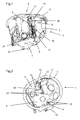
- Figure 1 is a perspective view of the installation box 1 from beneath.
- the mounting device 8 is shown in figure 1 in a mounted state.
- Figure 2 is a perspective view of the installation box 1 from above, wherewith the supportive part 14 extends around the elongate element 12 in on that side which faces inwardly towards the box interior.
- the mounting device 13 is herewith supported by the elongate element 12 therewith obviating the risk of it falling and being lost.
- two stop members 23, 24 are provided in the box interior on the bottom 2 of the box 1.
- the stop member 23 prevents movement of the elongate element 12 towards the centre axis of the box 1, while the stop member 24 prevents movement of the elongate element 11 (not shown) towards the centre axis of the box 1.
- a gripping element 25 is also disposed on the inside of the elongate element 12 so as to facilitate swinging of the elongate element 12 inwardly towards the box interior.
- Figure 3 is a perspective view of the installation box 1 with its bottom 2 facing upwards.
- the mounting device 13 is shown in a non-mounted position or rest position.
- the surface of the elongate element 12 that faces outwardly from the box 1 includes a number of teeth or serrations.
- the supportive part 14 of the mounting device 13 is provided with a tooth (not shown) so as to enable the device 13 to take fixed positions along the elongate element 12. These fixed positions are utilized in holding the box 1 in position in connection with mounting the electrical arrangement in the box 1, for instance when desiring to make adjustments with respect to any angular errors when mounting an electric arrangement.
- the electrical device can be mounted in the box 1.
- the two screws 6, 16 (see figure 2 and figure 4) are now unscrewed or backed-off a number of turns so as to enable the electrical device to be fastened to the box 1 with the aid of the two screws 6, 16.
- the box 1 will still be firmly fastened behind the panel.
- the teeth on the supportive part 9, 14 of the mounting device 8, 13 cause the mounting device 8, 13 to remain in engagement with the teeth on the elongate element 11, 12, even though the screws 6, 16 have been loosened and therewith prevent the mounting device 8, 13 from moving along the elongate element 11, 12.
- Figure 4 shows the installation box 1 with its bottom 2 facing upwards.
- the two mounting devices 8, 13 are disposed opposite one another on the side wall 3 of the box.
- Figure 4 shows the mounting devices 8, 13 in their mounting position.
Landscapes
- Engineering & Computer Science (AREA)
- Architecture (AREA)
- Civil Engineering (AREA)
- Structural Engineering (AREA)
- Casings For Electric Apparatus (AREA)
- Details Of Rigid Or Semi-Rigid Containers (AREA)
- Connection Or Junction Boxes (AREA)
- Supports Or Holders For Household Use (AREA)
- Hinges (AREA)
- Connection Of Plates (AREA)
Abstract
Description
- The present invention relates to an installation box of the kind defined in the preamble of
claim 1. In particular, the invention relates to an improved installation box that includes mounting elements which can be adapted to the thickness of the wall in which they are to be mounted. - Installation boxes, or flush mounted installation boxes, are used in the installation of electric devices in buildings so as to enable the provision of an insulated or isolated cavity for connection points and the connection of different types of electrical contact devices and electric sockets.
- When installing electrical elements in newly built wall and ceiling constructions flush mounted installation boxes are secured either by nailing the box to a baton or post belonging to the wall/ceiling, or by securing them in concrete in the case, for instance, of a reinforced wall construction or ceiling construction.
- When, for instance, wall/ceiling mounted electrical installations need to be complemented with a flush mounted installation box there is used conveniently a box with which the installer is able to activate mounting elements with the aid of screws so that fitting of the box can be adapted to the thickness of a wall or ceiling panel in which the box shall be fitted. When using an installation box of this nature it is desirable that the box can be readily inserted into and removed from a box mounting cavity, provided for instance in a wall or ceiling panel, without the mounting elements hooking onto the edges of the cavity and therewith making it difficult to fit and remove the box into and out of said cavity. It is also desirable that the mounting elements can be adjusted continuously and smoothly with as few screws as possible, so as to enable the box to be fitted in walls of different panel thicknesses, and to enable electrical devices to be fastened in the box with the aid of the same screws at the same time as the box is mounted in the wall. It is also desirable that the installation box will fulfill the IP4x-encapsulating class requirements, i.e. will afford protection against solid objects that are larger than 1.0 mm and that has a construction which prevents the mounting elements from being deformed or from twisting when the screws are tightened and which will also prevent loosening of the mounting elements when removing or dismantling the installation box. It is also desirable to be able to adjust any angular errors when fitting the electrical devices.
- An installation box that includes four screws is known in the art. Two of the screws are intended to activate inwardly pivotal and outwardly pivotal holding elements which enable the box to be mounted in a wall or ceiling panel. The other screws are intended for fastening electrical devices in the installation box. Prior to inserting the box into or removing the box from a wall or ceiling panel, the holding elements are moved to an inwardly swung position. In this inwardly swung position, the holding elements lie inwardly of the box profile in a space provided in the box for each holding element. One drawback with this type of box is that when dismantling the box from a wall panel or ceiling panel, or when adjusting the box to correct any angular errors that may occur, the installer is forced to rely upon sufficient friction in the screw thread in order for the holding elements to rotate into the element accommodating space. It is also very difficult to know when the holding element is located in a position in which it can be swung into the accommodating space. The difficulty in determining the position of the holding element on the screw and the fact that there is nothing to prevent the holding element from being unscrewed fully means that there is a significant danger of the holding element being lost should the installer unscrew the screw too far. Another drawback with this type of installation box is that adjustment of the box in order to rectify angular errors is a complicated process due to the fact that the installer needs to adjust all four screws in order to obtain an effective result.
-
FR2839818 - The object of the present invention is to provide a solution to the aforesaid problems with the aid of an improved installation box of the kind described.
- This object is achieved by the present invention as defined in the
independent claim 1. Suitable embodiments of the present invention are made apparent in the dependent claims. - Thus, the present invention comprises an installation box which includes a box body that has a bottom and a side wall disposed generally at right angles to said bottom, and at least one screw which is intended to activate a respective mounting element which enables the installation box to be flush mounted in a wall or ceiling cavity, wherein an edge of said side wall defines an opening on the box body opposite to said bottom, wherein the side wall includes at least one elongate side opening which extends from said edge and down towards the bottom of the box body, wherein at least one of said at least one side opening is covered at least partially by an elongate element which is pivotally mounted in the wall of the box body wherein said screws extend along said elongate element, which is intended to support respective mounting devices, characterized in that the pivot axle of the elongate element is situated at said edge.
- The invention affords the advantage that when the installation box shall be mounted in a mounting cavity it is possible to swing the elongate elements and the mounting devices inwardly towards the interior of the box. This increases the opening between the box and the edge of the mounting cavity, therewith enabling the mounting devices to be moved beyond and in behind a wall or ceiling panel. The position of the box can then be adjusted with the aid of screws intended for mounting the box against the rear side of the panel.
- According to one advantageous embodiment of the invention, at least one of said mounting devices can include a supportive portion and a shelf structure that extends generally at right angles to said supportive part and that the screws can pass through the supportive part in order to allow continuous adjustment of the position of the mounting device along the elongate element. This enables mounting of the installation box to be adapted for mounting of the box in panels of mutually different thicknesses.
- One surface of at least one of said elongate elements that face out from the body of the box may be provided with teeth or serrations and one surface of the supportive part that faces towards said serrated surface of the elongate element may conveniently be provided with at least one tooth. When the positions of the mounting devices has been adjust in accordance with the thickness of the panel in which the box shall be mounted, this solution enables the screws to be unscrewed to an extents sufficient to secure an electric device in the installation box without moving the mounting device out of position. Moreover, when the box needs to be brought into alignment with a mounting cavity, the installer is able to unscrew the screws a number of turns, and snap down the mounting device a number of notches on the serrated surface of the elongate element, and adjust the electric device so that it will fit in the box at the same time as the mounting device holds the box in position against the panel, and thereafter conveniently screw the box and the electric device firmly in the panel cavity.
- According to another advantageous embodiment of the invention, the box body may include at least one guide part that extends from the edge of said side wall down towards the bottom of the box, on at least one side of and along part of each side opening. The benefit thus afforded is that the torque generated by the screws is not transferred as torque on the mounting device and the elongate element. The guide parts result in stable passage of a mounting device along the elongate element and therewith effective abutment with the rear side of the panel which in turn results in satisfactory mounting of the installation box in the mounting cavity. Said at least one guide part and the box body may, for instance, be designed to enable a respective mounting device that is in a non-mounted position to be swung into the interior of the box together with the elongate element so as to facilitate insertion of the box into a mounting cavity.
- According to another beneficial embodiment of the invention, part of the shelf of a mounting device may, when mounted, extend out from a respective elongate element beyond said at least one guide part. The shelf is thus given a larger surface area, which, in turn, provides effective abutment with the rear side of the panel and stable mounting of the box in the mounting cavity.
- According to another beneficial embodiment of the present invention the part of a mounted shelf that extends beyond said at least one guide part extends over each guide part. This prevents the elongate element and the mounting device from swinging in towards the interior of the box in a mounted state.
- According to yet another beneficial embodiment of the invention a supportive member may be disposed on the underside of the shelf in order to relieve the shelf of forces acting at right angles thereon.
- According to yet another beneficial embodiment of the invention, the supportive member of said at least one mounting device extends in on that side of the elongate element which faces towards the box interior. One advantage afforded by this solution is that the mounting device will constantly lie against the elongate element and can not therefore fall and be lost
- According to still another beneficial embodiment of the invention, a projection may extend out from the body of the box adjacent at least one end of a side opening nearest the bottom of the box body. One advantage afforded in this way is that an installer is able to draw the mounting device down to a stop position without losing the mounting device. In this state, the installer is also aware that the mounting device is in a non-mounted position and is therefore able to move the mounting device and the elongate element in towards the box interior and readily disassemble the box in said panel cavity.
- According to another beneficial embodiment of the invention a gripping element may be provided on a surface of at least one of said at least one elongate element that faces towards the box interior. In a mounted state, this enables the installer to readily grip the elongate element so as to be able to move said element and the mounting device towards the box interior.
- According to another beneficial embodiment of the invention, at least one stop means may be provided on the bottom of the installation box inwardly inside each side opening. This solution is intended to prevent an elongate element and a mounting device from moving further in towards the centre of the box body in a non-mounted state of the installation, such that the outer edge of the shelf lies level with the box body. This solution ensures that the installation box fulfils the IP4x encapsulating class, i.e. protection against solid objects that are greater than 1.0 mm, and that the screws are not exposed in the coupling cavity.
- According to still another beneficial embodiment of the invention, the screws may be intended for securing an electrical device in the installation box. This provides the benefit of enabling one and the same screw to be used for mounting an electrical device in the installation box and also for mounting the installation box in a mounting cavity.
- The invention will now be described in more detail with reference to an exemplifying embodiment thereof and also with reference to the accompanying drawings, in which
- Fig. 1 is a perspective view of one embodiment of an installation box according to the present invention taken from beneath with the mounting device in a mounted position;
- Fig. 2 is a perspective view of the installation box as seen from above;
- Fig. 3 is a perspective view of the inventive installation box with the underside of the box facing upwards and with the mounting device in a non-mounted position or rest position; and
- Fig. 4 illustrates the inventive installation box with its bottom facing upwards.
- Figures 1-4 illustrate an embodiment of a flush-mounted installation box or enclosure that can be adjusted smoothly and continuously in accord with the thickness of a panel in which the installation box shall be mounted. It is emphasized that the invention is not restricted to this type of installation box and that the invention can be applied to all manner of available installation boxes.
- The installation box shown in figures 1-4 includes a body that has a bottom 2 connected to a
side wall 3. Theside wall 3 includes anedge 4 which defines anopening 5 on the body of the box. Theopening 5 is located centrally opposite thebottom 2 of the box and is intended to provide a mounting cavity for different types of electrical contact devices and power outlets or power points of different kinds. Theside wall 3 also includes two elongate side openings which extend from theedge 4 of theside wall 3 and down to thebottom 2 of thebox 1. In the case of the illustrated embodiment, these elongate side openings are located centrally opposite one another on the generallyoval installation box 1, although said side openings may, of course, be placed relative to one another in other ways. The elongate side openings are covered by a respective pivotally disposed elongate element, 11, 12 having pivot axles located at theedge 4 of theside wall 3 of said body. In order to enable thebox 1 to be mounted in a mounting cavity there is provided a mountingelement supportive part shelf structure supportive part elongate elements devices elongate elements respective screw screws edge 4 of theside wall 3 of the box extend along theelongate elements supportive part elements guide part guide parts edge 4 of theside wall 3 down towards thebottom 2 of the box body, are intended to prevent torque generated by thescrews device elongate element device elongate element shelf structure guide parts - When the
installation box 1 shall be inserted into a mounting cavity, for instance in the wall or ceiling of a building structure, the mountingdevices respective projection bottom 2 of thebox 1. Theprojection device device screws supportive part device device projection device elongate element device projection guide part bottom 2 of thebox 1. By swinging the mountingdevice box 1, the distance between thebox 1 and the edge of the mounting cavity is increased sufficiently for thebox 1 to be easily inserted into the mounting cavity. When thebox 1 has been inserted effectively into the mounting cavity, the mountingdevice elongate element devices respective screws shelf structure device installation box 1 is now mounted in the mounting cavity. - Figure 1 is a perspective view of the
installation box 1 from beneath. The mountingdevice 8 is shown in figure 1 in a mounted state. - Figure 2 is a perspective view of the
installation box 1 from above, wherewith thesupportive part 14 extends around theelongate element 12 in on that side which faces inwardly towards the box interior. Although not shown, the mountingdevice 13 is herewith supported by theelongate element 12 therewith obviating the risk of it falling and being lost. As shown in figure 2, twostop members bottom 2 of thebox 1. Thestop member 23 prevents movement of theelongate element 12 towards the centre axis of thebox 1, while thestop member 24 prevents movement of the elongate element 11 (not shown) towards the centre axis of thebox 1. A grippingelement 25 is also disposed on the inside of theelongate element 12 so as to facilitate swinging of theelongate element 12 inwardly towards the box interior. - Figure 3 is a perspective view of the
installation box 1 with its bottom 2 facing upwards. In this figure the mountingdevice 13 is shown in a non-mounted position or rest position. The surface of theelongate element 12 that faces outwardly from thebox 1 includes a number of teeth or serrations. Correspondingly, thesupportive part 14 of the mountingdevice 13 is provided with a tooth (not shown) so as to enable thedevice 13 to take fixed positions along theelongate element 12. These fixed positions are utilized in holding thebox 1 in position in connection with mounting the electrical arrangement in thebox 1, for instance when desiring to make adjustments with respect to any angular errors when mounting an electric arrangement. - When the
box 1 has been mounted behind a wall, the electrical device can be mounted in thebox 1. The twoscrews 6, 16 (see figure 2 and figure 4) are now unscrewed or backed-off a number of turns so as to enable the electrical device to be fastened to thebox 1 with the aid of the twoscrews screws box 1 will still be firmly fastened behind the panel. The teeth on thesupportive part device device elongate element screws device elongate element box 1, thescrews box 1 and the electrical device are held mounted in the panel cavity. Moreover, asupportive device shelf structure shelf structure - Figure 4 shows the
installation box 1 with its bottom 2 facing upwards. The twomounting devices side wall 3 of the box. Figure 4 shows the mountingdevices
Claims (12)
- An installation box comprising a body that includes a bottom (2) and a side wall (3) disposed generally at right angles to said bottom (2), and at least one screw (6, 16) which functions to activate a respective mounting device (8, 13) so as to enable the installation box (1) to be mounted in a wall or ceiling cavity, wherein the side wall (3) includes an edge (4) which defines an opening (5) on the box body opposite said bottom (2), wherein the side wall (3) includes at least one elongate side opening that extends from said edge (4) down to the bottom (2) of the box body, wherein at least one of said at least one side opening is covered at least partially by an elongate element (11, 12) which is pivotally disposed in the wall (3) of said body wherein said screws (6, 16) extend along said elongate element (11, 12), and wherein the elongate element (11, 12) is intended to function as a support for respective mounting devices (8, 13), and wherein the pivot axis of the elongate element (11, 12) is located adjacent said edge (4), characterized by a projection (21, 22) which extends out from the body of the box at at least one end of a side opening nearest the bottom (2) of the box body.
- An installation box according to claim 1, characterized in that at least one of the mounting devices (8, 13) includes a supportive part (9, 14) and a shelf structure (10, 15) generally at right angles to said supportive part (9, 14); and in that said screw (6, 16) extends through the supportive part (9, 14) so as to enable the position of the mounting device (8, 13) to be adjusted smoothly and continuously along the elongate element (11, 12).
- An installation box according to claim 2, characterized in that a surface of at least one of said elongate elements (11, 12) that faces out from the box body is provided with teeth; and in that a surface of the supportive part (9, 14) that faces towards said surface of the elongate element (11, 12) is provided with at least one tooth.
- An installation box according to any one of claims 1-3, characterized by at least one guide part (17, 18, 19, 20) which projects out from the box body and which extends from the edge (4) of said side wall (3) down towards the bottom (2) of the box body on at least one side of and along a part of each side opening.
- An installation box according to claim 4, characterized in that said at least one guide part (17, 18, 19, 20) and the box body are constructed so that with respective mounting devices (8, 13) in a non-mounted position said devices (8, 13) can be swung together with the elongate element (11, 12) in towards the interior of the box (1) to facilitate insertion of the box (1) into a mounting cavity.
- An installation box according to any one of claims 4-5, characterized in that in a mounted state the shelf structure (10, 15) of a mounting device (8, 13) extends out from a respective elongate element (11, 12) beyond said at least one guide part (17, 18, 19, 20).
- An installation box according to claim 6, characterized in that said part of a mounted shelf structure (10, 15) that extends beyond said at least one guide part (17, 18, 19, 20) also extends over each guide part (17, 18, 19, 20) such as to prevent the elongate element (11, 12) and the mounting device (8, 13) swinging in towards the box interior in a mounted state.
- An installation box according to any one of claims 2-7, characterized by a supportive device (26, 27) provided on the underside of the shelf structure (10, 15) so as to relieve the shelf structure (10, 15) of forces that act perpendicularly on said structure.
- An installation box according to any one of claims 2-8, characterized in that the supportive part (9, 14) of said at least one mounting device (8, 13) extends in on that side of the elongate element (11, 12) that faces towards the box interior.
- An installation box according to any one of the preceding claims, characterized by a gripping element (25) disposed on a surface of at least one of said at least one elongate element (11, 12) that faces towards the box interior.
- An installation box according to any one of claims 2-10, characterized in that there is provided in the box interior on the bottom (2) of said box (1) inwardly of each side opening at least one stop member (23, 24) in order to prevent an elongate element (11, 12) and a mounting device (8, 13) from moving further in towards the centre of the box body to an extent such that the outer edge of the shelf structure (10, 15) will lie level with the box body in the non-mounted state of the installation box (1).
- An installation box according to any one of the preceding claims, characterized in that the screws (6, 16) are intended for fastening an electrical device in the installation box (1).
Applications Claiming Priority (1)
| Application Number | Priority Date | Filing Date | Title |
|---|---|---|---|
| SE0501811A SE530543C2 (en) | 2005-08-12 | 2005-08-12 | Installation box with steplessly adjustable mounting means |
Publications (3)
| Publication Number | Publication Date |
|---|---|
| EP1768220A2 true EP1768220A2 (en) | 2007-03-28 |
| EP1768220A3 EP1768220A3 (en) | 2010-06-02 |
| EP1768220B1 EP1768220B1 (en) | 2017-07-19 |
Family
ID=37714637
Family Applications (1)
| Application Number | Title | Priority Date | Filing Date |
|---|---|---|---|
| EP06118537.7A Not-in-force EP1768220B1 (en) | 2005-08-12 | 2006-08-07 | Installation box with continuously adjustable mounting members |
Country Status (4)
| Country | Link |
|---|---|
| EP (1) | EP1768220B1 (en) |
| ES (1) | ES2643618T3 (en) |
| NO (1) | NO336531B1 (en) |
| SE (1) | SE530543C2 (en) |
Citations (1)
| Publication number | Priority date | Publication date | Assignee | Title |
|---|---|---|---|---|
| FR2839818A1 (en) | 2002-05-17 | 2003-11-21 | Alombard Sa | Box with clamps used to embed an electric apparatus, e.g. switch or power outlet, into a hollow closure in a building, has pivoting clamps each allowed to move in translation and/or rotation |
Family Cites Families (3)
| Publication number | Priority date | Publication date | Assignee | Title |
|---|---|---|---|---|
| DE4241390C2 (en) * | 1992-12-09 | 1997-11-20 | Kaiser Gmbh & Co Kg | Electrical cavity wall box, such as switch box, junction box or the like. |
| FR2762941B1 (en) * | 1997-04-30 | 1999-07-30 | Legrand Sa | RECESSED BOX FOR DRY PARTITION WITH TIE-DOWN LEG (S) INITIALLY ON ONE HOLDER, IN PARTICULAR FOR ELECTRICAL EQUIPMENT |
| FR2781097B1 (en) * | 1998-07-08 | 2000-10-13 | Legrand Sa | RECESSED BOX FOR DRY PARTITION WITH TIE-DOWN LEG (S) INITIALLY ON ONE HOLDER, ESPECIALLY FOR ELECTRICAL EQUIPMENT |
-
2005
- 2005-08-12 SE SE0501811A patent/SE530543C2/en not_active IP Right Cessation
-
2006
- 2006-08-07 EP EP06118537.7A patent/EP1768220B1/en not_active Not-in-force
- 2006-08-07 ES ES06118537.7T patent/ES2643618T3/en active Active
- 2006-08-11 NO NO20063649A patent/NO336531B1/en not_active IP Right Cessation
Patent Citations (1)
| Publication number | Priority date | Publication date | Assignee | Title |
|---|---|---|---|---|
| FR2839818A1 (en) | 2002-05-17 | 2003-11-21 | Alombard Sa | Box with clamps used to embed an electric apparatus, e.g. switch or power outlet, into a hollow closure in a building, has pivoting clamps each allowed to move in translation and/or rotation |
Also Published As
| Publication number | Publication date |
|---|---|
| ES2643618T3 (en) | 2017-11-23 |
| EP1768220A3 (en) | 2010-06-02 |
| SE0501811L (en) | 2007-02-13 |
| EP1768220B1 (en) | 2017-07-19 |
| SE530543C2 (en) | 2008-07-01 |
| NO336531B1 (en) | 2015-09-21 |
| NO20063649L (en) | 2007-02-13 |
Similar Documents
| Publication | Publication Date | Title |
|---|---|---|
| US7002076B2 (en) | Electric box extender | |
| US6573446B1 (en) | Apparatus for mounting an electrical component on a structure | |
| US7449633B2 (en) | Electrical box for concrete walls | |
| US7494371B2 (en) | Pronged, screwless face plate | |
| US8371465B2 (en) | Electrical box extension sleeve | |
| US8076578B1 (en) | Adjustable electrical outlet box assembly | |
| CA2551509C (en) | Pull out extension contained in electrical box | |
| US7342173B1 (en) | Multi-directional-port junction box | |
| US20080223600A1 (en) | Two-gang adjustable mud ring | |
| US11088518B2 (en) | Mounting mechanism for an electrical device | |
| CA3030566A1 (en) | Solar panel mounting clamp and system | |
| US7799992B2 (en) | Cover plate for surface mount junction box with locking member | |
| CA2682445A1 (en) | Plastic cable clamps designs in steel outlet boxes | |
| US4673235A (en) | Subplate for a low-voltage electric outlet | |
| US20030079898A1 (en) | Clip-on cover plate for electrical fixtures | |
| US9362731B2 (en) | Single-fastener mounting plate for electrical outlets | |
| CA2543167A1 (en) | Rock-n-lock non-metallic snap-on electrical box | |
| EP1768220B1 (en) | Installation box with continuously adjustable mounting members | |
| US4889299A (en) | Duct mounting fixture for securing a duct on a support section | |
| US6468107B1 (en) | Rectangular shim for electrical receptacle or switch | |
| EP3886280B1 (en) | Electric installation system | |
| EP3506444B1 (en) | Surface mounting device | |
| EP1944847B1 (en) | Installation box with removable mounting device | |
| EP2683045B1 (en) | Quick fix fixing arrangement | |
| EP3096424B1 (en) | Flexibler klauengriff zum befestigen eines elementes in einer box und mit diesem klauengriff zu befestigendes element |
Legal Events
| Date | Code | Title | Description |
|---|---|---|---|
| PUAI | Public reference made under article 153(3) epc to a published international application that has entered the european phase |
Free format text: ORIGINAL CODE: 0009012 |
|
| AK | Designated contracting states |
Kind code of ref document: A2 Designated state(s): AT BE BG CH CY CZ DE DK EE ES FI FR GB GR HU IE IS IT LI LT LU LV MC NL PL PT RO SE SI SK TR |
|
| AX | Request for extension of the european patent |
Extension state: AL BA HR MK YU |
|
| PUAL | Search report despatched |
Free format text: ORIGINAL CODE: 0009013 |
|
| AK | Designated contracting states |
Kind code of ref document: A3 Designated state(s): AT BE BG CH CY CZ DE DK EE ES FI FR GB GR HU IE IS IT LI LT LU LV MC NL PL PT RO SE SI SK TR |
|
| AX | Request for extension of the european patent |
Extension state: AL BA HR MK RS |
|
| 17P | Request for examination filed |
Effective date: 20101014 |
|
| AKX | Designation fees paid |
Designated state(s): AT BE BG CH CY CZ DE DK EE ES FI FR GB GR HU IE IS IT LI LT LU LV MC NL PL PT RO SE SI SK TR |
|
| 17Q | First examination report despatched |
Effective date: 20110405 |
|
| GRAP | Despatch of communication of intention to grant a patent |
Free format text: ORIGINAL CODE: EPIDOSNIGR1 |
|
| INTG | Intention to grant announced |
Effective date: 20170329 |
|
| GRAS | Grant fee paid |
Free format text: ORIGINAL CODE: EPIDOSNIGR3 |
|
| GRAA | (expected) grant |
Free format text: ORIGINAL CODE: 0009210 |
|
| AK | Designated contracting states |
Kind code of ref document: B1 Designated state(s): AT BE BG CH CY CZ DE DK EE ES FI FR GB GR HU IE IS IT LI LT LU LV MC NL PL PT RO SE SI SK TR |
|
| REG | Reference to a national code |
Ref country code: GB Ref legal event code: FG4D |
|
| REG | Reference to a national code |
Ref country code: CH Ref legal event code: EP |
|
| REG | Reference to a national code |
Ref country code: IE Ref legal event code: FG4D |
|
| REG | Reference to a national code |
Ref country code: AT Ref legal event code: REF Ref document number: 911246 Country of ref document: AT Kind code of ref document: T Effective date: 20170815 |
|
| REG | Reference to a national code |
Ref country code: DE Ref legal event code: R096 Ref document number: 602006053045 Country of ref document: DE |
|
| REG | Reference to a national code |
Ref country code: FR Ref legal event code: PLFP Year of fee payment: 12 |
|
| REG | Reference to a national code |
Ref country code: SE Ref legal event code: TRGR |
|
| REG | Reference to a national code |
Ref country code: NL Ref legal event code: MP Effective date: 20170719 |
|
| REG | Reference to a national code |
Ref country code: ES Ref legal event code: FG2A Ref document number: 2643618 Country of ref document: ES Kind code of ref document: T3 Effective date: 20171123 |
|
| REG | Reference to a national code |
Ref country code: LT Ref legal event code: MG4D |
|
| REG | Reference to a national code |
Ref country code: AT Ref legal event code: MK05 Ref document number: 911246 Country of ref document: AT Kind code of ref document: T Effective date: 20170719 |
|
| PG25 | Lapsed in a contracting state [announced via postgrant information from national office to epo] |
Ref country code: NL Free format text: LAPSE BECAUSE OF FAILURE TO SUBMIT A TRANSLATION OF THE DESCRIPTION OR TO PAY THE FEE WITHIN THE PRESCRIBED TIME-LIMIT Effective date: 20170719 Ref country code: AT Free format text: LAPSE BECAUSE OF FAILURE TO SUBMIT A TRANSLATION OF THE DESCRIPTION OR TO PAY THE FEE WITHIN THE PRESCRIBED TIME-LIMIT Effective date: 20170719 Ref country code: LT Free format text: LAPSE BECAUSE OF FAILURE TO SUBMIT A TRANSLATION OF THE DESCRIPTION OR TO PAY THE FEE WITHIN THE PRESCRIBED TIME-LIMIT Effective date: 20170719 Ref country code: FI Free format text: LAPSE BECAUSE OF FAILURE TO SUBMIT A TRANSLATION OF THE DESCRIPTION OR TO PAY THE FEE WITHIN THE PRESCRIBED TIME-LIMIT Effective date: 20170719 |
|
| PG25 | Lapsed in a contracting state [announced via postgrant information from national office to epo] |
Ref country code: GR Free format text: LAPSE BECAUSE OF FAILURE TO SUBMIT A TRANSLATION OF THE DESCRIPTION OR TO PAY THE FEE WITHIN THE PRESCRIBED TIME-LIMIT Effective date: 20171020 Ref country code: BG Free format text: LAPSE BECAUSE OF FAILURE TO SUBMIT A TRANSLATION OF THE DESCRIPTION OR TO PAY THE FEE WITHIN THE PRESCRIBED TIME-LIMIT Effective date: 20171019 Ref country code: IS Free format text: LAPSE BECAUSE OF FAILURE TO SUBMIT A TRANSLATION OF THE DESCRIPTION OR TO PAY THE FEE WITHIN THE PRESCRIBED TIME-LIMIT Effective date: 20171119 Ref country code: LV Free format text: LAPSE BECAUSE OF FAILURE TO SUBMIT A TRANSLATION OF THE DESCRIPTION OR TO PAY THE FEE WITHIN THE PRESCRIBED TIME-LIMIT Effective date: 20170719 Ref country code: PL Free format text: LAPSE BECAUSE OF FAILURE TO SUBMIT A TRANSLATION OF THE DESCRIPTION OR TO PAY THE FEE WITHIN THE PRESCRIBED TIME-LIMIT Effective date: 20170719 |
|
| REG | Reference to a national code |
Ref country code: CH Ref legal event code: PL |
|
| REG | Reference to a national code |
Ref country code: DE Ref legal event code: R097 Ref document number: 602006053045 Country of ref document: DE |
|
| PG25 | Lapsed in a contracting state [announced via postgrant information from national office to epo] |
Ref country code: RO Free format text: LAPSE BECAUSE OF FAILURE TO SUBMIT A TRANSLATION OF THE DESCRIPTION OR TO PAY THE FEE WITHIN THE PRESCRIBED TIME-LIMIT Effective date: 20170719 Ref country code: CH Free format text: LAPSE BECAUSE OF NON-PAYMENT OF DUE FEES Effective date: 20170831 Ref country code: MC Free format text: LAPSE BECAUSE OF FAILURE TO SUBMIT A TRANSLATION OF THE DESCRIPTION OR TO PAY THE FEE WITHIN THE PRESCRIBED TIME-LIMIT Effective date: 20170719 Ref country code: LI Free format text: LAPSE BECAUSE OF NON-PAYMENT OF DUE FEES Effective date: 20170831 Ref country code: CZ Free format text: LAPSE BECAUSE OF FAILURE TO SUBMIT A TRANSLATION OF THE DESCRIPTION OR TO PAY THE FEE WITHIN THE PRESCRIBED TIME-LIMIT Effective date: 20170719 Ref country code: DK Free format text: LAPSE BECAUSE OF FAILURE TO SUBMIT A TRANSLATION OF THE DESCRIPTION OR TO PAY THE FEE WITHIN THE PRESCRIBED TIME-LIMIT Effective date: 20170719 |
|
| PLBE | No opposition filed within time limit |
Free format text: ORIGINAL CODE: 0009261 |
|
| STAA | Information on the status of an ep patent application or granted ep patent |
Free format text: STATUS: NO OPPOSITION FILED WITHIN TIME LIMIT |
|
| REG | Reference to a national code |
Ref country code: IE Ref legal event code: MM4A |
|
| PG25 | Lapsed in a contracting state [announced via postgrant information from national office to epo] |
Ref country code: SK Free format text: LAPSE BECAUSE OF FAILURE TO SUBMIT A TRANSLATION OF THE DESCRIPTION OR TO PAY THE FEE WITHIN THE PRESCRIBED TIME-LIMIT Effective date: 20170719 Ref country code: IT Free format text: LAPSE BECAUSE OF FAILURE TO SUBMIT A TRANSLATION OF THE DESCRIPTION OR TO PAY THE FEE WITHIN THE PRESCRIBED TIME-LIMIT Effective date: 20170719 Ref country code: EE Free format text: LAPSE BECAUSE OF FAILURE TO SUBMIT A TRANSLATION OF THE DESCRIPTION OR TO PAY THE FEE WITHIN THE PRESCRIBED TIME-LIMIT Effective date: 20170719 |
|
| REG | Reference to a national code |
Ref country code: BE Ref legal event code: MM Effective date: 20170831 |
|
| 26N | No opposition filed |
Effective date: 20180420 |
|
| GBPC | Gb: european patent ceased through non-payment of renewal fee |
Effective date: 20171019 |
|
| PG25 | Lapsed in a contracting state [announced via postgrant information from national office to epo] |
Ref country code: LU Free format text: LAPSE BECAUSE OF NON-PAYMENT OF DUE FEES Effective date: 20170807 |
|
| PG25 | Lapsed in a contracting state [announced via postgrant information from national office to epo] |
Ref country code: GB Free format text: LAPSE BECAUSE OF NON-PAYMENT OF DUE FEES Effective date: 20171019 Ref country code: IE Free format text: LAPSE BECAUSE OF NON-PAYMENT OF DUE FEES Effective date: 20170807 |
|
| REG | Reference to a national code |
Ref country code: FR Ref legal event code: PLFP Year of fee payment: 13 |
|
| PG25 | Lapsed in a contracting state [announced via postgrant information from national office to epo] |
Ref country code: SI Free format text: LAPSE BECAUSE OF FAILURE TO SUBMIT A TRANSLATION OF THE DESCRIPTION OR TO PAY THE FEE WITHIN THE PRESCRIBED TIME-LIMIT Effective date: 20170719 Ref country code: BE Free format text: LAPSE BECAUSE OF NON-PAYMENT OF DUE FEES Effective date: 20170831 |
|
| PG25 | Lapsed in a contracting state [announced via postgrant information from national office to epo] |
Ref country code: HU Free format text: LAPSE BECAUSE OF FAILURE TO SUBMIT A TRANSLATION OF THE DESCRIPTION OR TO PAY THE FEE WITHIN THE PRESCRIBED TIME-LIMIT; INVALID AB INITIO Effective date: 20060807 |
|
| PG25 | Lapsed in a contracting state [announced via postgrant information from national office to epo] |
Ref country code: CY Free format text: LAPSE BECAUSE OF NON-PAYMENT OF DUE FEES Effective date: 20170719 |
|
| PGFP | Annual fee paid to national office [announced via postgrant information from national office to epo] |
Ref country code: SE Payment date: 20190816 Year of fee payment: 14 Ref country code: ES Payment date: 20190906 Year of fee payment: 14 Ref country code: DE Payment date: 20190819 Year of fee payment: 14 Ref country code: FR Payment date: 20190815 Year of fee payment: 14 |
|
| PG25 | Lapsed in a contracting state [announced via postgrant information from national office to epo] |
Ref country code: TR Free format text: LAPSE BECAUSE OF FAILURE TO SUBMIT A TRANSLATION OF THE DESCRIPTION OR TO PAY THE FEE WITHIN THE PRESCRIBED TIME-LIMIT Effective date: 20170719 |
|
| PG25 | Lapsed in a contracting state [announced via postgrant information from national office to epo] |
Ref country code: PT Free format text: LAPSE BECAUSE OF FAILURE TO SUBMIT A TRANSLATION OF THE DESCRIPTION OR TO PAY THE FEE WITHIN THE PRESCRIBED TIME-LIMIT Effective date: 20170719 |
|
| REG | Reference to a national code |
Ref country code: DE Ref legal event code: R119 Ref document number: 602006053045 Country of ref document: DE |
|
| REG | Reference to a national code |
Ref country code: SE Ref legal event code: EUG |
|
| PG25 | Lapsed in a contracting state [announced via postgrant information from national office to epo] |
Ref country code: SE Free format text: LAPSE BECAUSE OF NON-PAYMENT OF DUE FEES Effective date: 20200808 |
|
| PG25 | Lapsed in a contracting state [announced via postgrant information from national office to epo] |
Ref country code: DE Free format text: LAPSE BECAUSE OF NON-PAYMENT OF DUE FEES Effective date: 20210302 Ref country code: FR Free format text: LAPSE BECAUSE OF NON-PAYMENT OF DUE FEES Effective date: 20200831 |
|
| REG | Reference to a national code |
Ref country code: ES Ref legal event code: FD2A Effective date: 20220110 |
|
| PG25 | Lapsed in a contracting state [announced via postgrant information from national office to epo] |
Ref country code: ES Free format text: LAPSE BECAUSE OF NON-PAYMENT OF DUE FEES Effective date: 20200808 |