EP1768087A1 - Procédé récursive et dispositif pour coder des valeurs de luminance dans des mots codés de sous-trames dans un dispositif d'affichage - Google Patents
Procédé récursive et dispositif pour coder des valeurs de luminance dans des mots codés de sous-trames dans un dispositif d'affichage Download PDFInfo
- Publication number
- EP1768087A1 EP1768087A1 EP05291973A EP05291973A EP1768087A1 EP 1768087 A1 EP1768087 A1 EP 1768087A1 EP 05291973 A EP05291973 A EP 05291973A EP 05291973 A EP05291973 A EP 05291973A EP 1768087 A1 EP1768087 A1 EP 1768087A1
- Authority
- EP
- European Patent Office
- Prior art keywords
- subfield
- bit
- code word
- luminance value
- line
- Prior art date
- Legal status (The legal status is an assumption and is not a legal conclusion. Google has not performed a legal analysis and makes no representation as to the accuracy of the status listed.)
- Withdrawn
Links
Images


Classifications
-
- H—ELECTRICITY
- H04—ELECTRIC COMMUNICATION TECHNIQUE
- H04N—PICTORIAL COMMUNICATION, e.g. TELEVISION
- H04N21/00—Selective content distribution, e.g. interactive television or video on demand [VOD]
- H04N21/20—Servers specifically adapted for the distribution of content, e.g. VOD servers; Operations thereof
- H04N21/23—Processing of content or additional data; Elementary server operations; Server middleware
- H04N21/238—Interfacing the downstream path of the transmission network, e.g. adapting the transmission rate of a video stream to network bandwidth; Processing of multiplex streams
- H04N21/2383—Channel coding or modulation of digital bit-stream, e.g. QPSK modulation
-
- G—PHYSICS
- G09—EDUCATION; CRYPTOGRAPHY; DISPLAY; ADVERTISING; SEALS
- G09G—ARRANGEMENTS OR CIRCUITS FOR CONTROL OF INDICATING DEVICES USING STATIC MEANS TO PRESENT VARIABLE INFORMATION
- G09G3/00—Control arrangements or circuits, of interest only in connection with visual indicators other than cathode-ray tubes
- G09G3/20—Control arrangements or circuits, of interest only in connection with visual indicators other than cathode-ray tubes for presentation of an assembly of a number of characters, e.g. a page, by composing the assembly by combination of individual elements arranged in a matrix no fixed position being assigned to or needed to be assigned to the individual characters or partial characters
- G09G3/2007—Display of intermediate tones
- G09G3/2018—Display of intermediate tones by time modulation using two or more time intervals
- G09G3/2022—Display of intermediate tones by time modulation using two or more time intervals using sub-frames
- G09G3/2033—Display of intermediate tones by time modulation using two or more time intervals using sub-frames with splitting one or more sub-frames corresponding to the most significant bits into two or more sub-frames
-
- G—PHYSICS
- G09—EDUCATION; CRYPTOGRAPHY; DISPLAY; ADVERTISING; SEALS
- G09G—ARRANGEMENTS OR CIRCUITS FOR CONTROL OF INDICATING DEVICES USING STATIC MEANS TO PRESENT VARIABLE INFORMATION
- G09G3/00—Control arrangements or circuits, of interest only in connection with visual indicators other than cathode-ray tubes
- G09G3/20—Control arrangements or circuits, of interest only in connection with visual indicators other than cathode-ray tubes for presentation of an assembly of a number of characters, e.g. a page, by composing the assembly by combination of individual elements arranged in a matrix no fixed position being assigned to or needed to be assigned to the individual characters or partial characters
-
- G—PHYSICS
- G09—EDUCATION; CRYPTOGRAPHY; DISPLAY; ADVERTISING; SEALS
- G09G—ARRANGEMENTS OR CIRCUITS FOR CONTROL OF INDICATING DEVICES USING STATIC MEANS TO PRESENT VARIABLE INFORMATION
- G09G2320/00—Control of display operating conditions
- G09G2320/02—Improving the quality of display appearance
- G09G2320/0233—Improving the luminance or brightness uniformity across the screen
-
- G—PHYSICS
- G09—EDUCATION; CRYPTOGRAPHY; DISPLAY; ADVERTISING; SEALS
- G09G—ARRANGEMENTS OR CIRCUITS FOR CONTROL OF INDICATING DEVICES USING STATIC MEANS TO PRESENT VARIABLE INFORMATION
- G09G2320/00—Control of display operating conditions
- G09G2320/02—Improving the quality of display appearance
- G09G2320/0266—Reduction of sub-frame artefacts
-
- G—PHYSICS
- G09—EDUCATION; CRYPTOGRAPHY; DISPLAY; ADVERTISING; SEALS
- G09G—ARRANGEMENTS OR CIRCUITS FOR CONTROL OF INDICATING DEVICES USING STATIC MEANS TO PRESENT VARIABLE INFORMATION
- G09G2320/00—Control of display operating conditions
- G09G2320/06—Adjustment of display parameters
- G09G2320/0673—Adjustment of display parameters for control of gamma adjustment, e.g. selecting another gamma curve
-
- G—PHYSICS
- G09—EDUCATION; CRYPTOGRAPHY; DISPLAY; ADVERTISING; SEALS
- G09G—ARRANGEMENTS OR CIRCUITS FOR CONTROL OF INDICATING DEVICES USING STATIC MEANS TO PRESENT VARIABLE INFORMATION
- G09G3/00—Control arrangements or circuits, of interest only in connection with visual indicators other than cathode-ray tubes
- G09G3/20—Control arrangements or circuits, of interest only in connection with visual indicators other than cathode-ray tubes for presentation of an assembly of a number of characters, e.g. a page, by composing the assembly by combination of individual elements arranged in a matrix no fixed position being assigned to or needed to be assigned to the individual characters or partial characters
- G09G3/2007—Display of intermediate tones
- G09G3/2018—Display of intermediate tones by time modulation using two or more time intervals
- G09G3/2022—Display of intermediate tones by time modulation using two or more time intervals using sub-frames
-
- G—PHYSICS
- G09—EDUCATION; CRYPTOGRAPHY; DISPLAY; ADVERTISING; SEALS
- G09G—ARRANGEMENTS OR CIRCUITS FOR CONTROL OF INDICATING DEVICES USING STATIC MEANS TO PRESENT VARIABLE INFORMATION
- G09G3/00—Control arrangements or circuits, of interest only in connection with visual indicators other than cathode-ray tubes
- G09G3/20—Control arrangements or circuits, of interest only in connection with visual indicators other than cathode-ray tubes for presentation of an assembly of a number of characters, e.g. a page, by composing the assembly by combination of individual elements arranged in a matrix no fixed position being assigned to or needed to be assigned to the individual characters or partial characters
- G09G3/2007—Display of intermediate tones
- G09G3/2044—Display of intermediate tones using dithering
Definitions
- the invention relates to a method and a device for encoding the luminance value of a pixel of a picture into a subfield code word in a display device. It can be applied to every display device using a PWM (Pulse Width Modulation) technology and subfields for displaying video picture.
- PWM Pulse Width Modulation
- the sub-field encoding part of a display using PWM technology is one of the most important parts of the display device since the encoding is responsible of the gray-scale portrayal (linearity and level of noise dithering) and of the motion rendition (level of false contour).
- the goal of the sub-field encoding is to fill up a sub-fields memory with subfields data.
- the subfield data of a pixel is a code word wherein each bit is representative of the state, "ON" or "OFF", of this pixel during a subfield.
- This sub-fields memory will be read during the next frame, sub-field by sub-field, whereas it is written pixel by pixel. This information is used directly to control the display device.
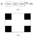
- the subfield encoding step is generally done after a degamma function as shown in Figure 1.
- the degamma function is first applied to the input luminance values. These values are then coded by the sub-field encoding step into subfield code words.
- the subfield encoding step is eventually preceded by a dithering step.
- the subfield code words are then stored in a subfields memory.
- the encoding step is implemented by using a simple look-up table.
- a subfield code word is associated to each luminance value.
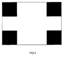
- the line load effect is illustrated by figures 2 and 3.
- the figure 2 shows a test picture to be displayed by a display device suffering from a problem of line load effect.
- the first and the last lines are black on half of the pixels, and white on the other half.
- the middle lines are white.
- the figure 3 shows the picture displayed by the display device.
- the line load effect is visible on the middle lines. This effect can be explained as follows: when a sub-field is used on a whole line its luminance is decreased by 20% compared to its luminance on a line where it is not used. The value of 20% is given as an example.
- the invention concerns a method for encoding the luminance value of a pixel of a picture into a subfield code word in a display device, wherein each bit of the subfield code word has a state "ON” or “OFF” and generates light emission during an own period called subfield when its state is "ON", the light emitted for a pixel by its subfield code word being representative of the luminance value of said pixel and the total duration of the subfields associated to the bits of the subfield code word forming the picture frame.
- the bits of each subfield code word are computed recursively one after the other such that the defects in the light emission generated by a bit of the subfield code word for said pixel is compensated by the following bits of the subfield code word.
- Each subfield has a weight proportional to its duration.
- the bits of each subfield code word are computed recursively in the descending order of the weights of the corresponding subfields from the bit associated to the subfield having the most significant weight to the bit associated to the subfield having the least significant weight.
- each bit of the subfield code word of a current pixel is computed by :
- the threshold value associated to a bit is equal to the sum of the weights of the subfields having a lower weight than the weight of the subfield corresponding to said bit plus one.
- the remaining luminance value to be encoded by a bit for a current pixel is computed as a function of the state of the pixels of the line of the display device to which the current pixel belongs.
- the remaining luminance value to be encoded by a current bit of the subfield code word of a current pixel is computed by :
- the invention concerns also to a device for encoding the luminance value of a pixel of a picture into a subfield code word in a display device, wherein each bit of the subfield code word has a state "ON” or "OFF” and generates light emission during an own period called subfield when its state is "ON", the light emitted for a pixel by its subfield code word being representative of the luminance value of said pixel and the total duration of the subfields associated to the bits of the subfield code word forming the picture frame.
- this device computes the bits of each subfield code word recursively one after the other such that the defects in the light emission generated by a bit of the subfield code word for said pixel is compensated by the following bits of the subfield code word.
- the device for computing each bit of the subfield code word of a current pixel, the device comprises:
- the invention is described in reference to a display device suffering from a problem of line load effect when displaying some pictures, it can be used to compensate for any luminance problem that can be estimated.
- the general idea of the recursive coding is to encode one sub-field after the other in order to be able to compensate for problems occurring on one sub-field with the other sub-fields. More particularly, the bits of a subfield code word are computed recursively one after the other such that the defects (e.g. line load and/or linearity) in the light emission or luminance generated by a bit of the subfield code word can be compensated by the following bits of the subfield code word.
- defects e.g. line load and/or linearity
- the bits of each subfield code word will be computed recursively in the descending order of the weights of the corresponding subfields from the most significant bit (MSB) associated to the subfield having the most significant weight to the least significant bit (LSB) associated to the subfield having the least significant weight.
- each bit of a subfield code word refers to a particular subfield among the plurality of subfields of the video frame
- luminance of a bit or "luminance of a subfield”.
- the luminance of a bit for a current pixel is calculated on the basis of the number of pixels having the preceding bit in the state "1" in the line of pixels to which the current pixel belongs .
- the luminance of a subfield can vary depending on the line load of the line of pixels to be displayed (number of pixels in a "ON" state in the considered line of pixels). So it is evaluated as soon as all required information is known. It can be evaluated at the end of the loading of the picture but in order to limit the time delay, it usually will be evaluated at the latest after each line.
- the luminance of a sub-field on a pixel is only a function of the pixel itself and the luminance of the pixel can be evaluated directly, the luminance of the sub-field is roughly the same for all pixels of the picture.
- the luminance on a line is dependent on the load distribution on this line (e.g. line load effect)
- the luminance of a sub-field can only be evaluated when the sub-field has been encoded for the whole line.
- the problem of line load effect is processed in a new way.
- the line-load effect is seen as a luminance loss on a line. Nevertheless it is equivalent to say that when a sub-field is used on a whole line its luminance is decreased by 20% in comparison to its luminance on a line where it is not used and to say that when the sub-field is not used on a line its luminance is increased by 25% compared to its luminance when it is used on the whole line.
- the reference luminance is different, but the effect is the same.
- the recursive encoding method is done line by line and sub-field by sub-field.
- the goal is to determine for each pixel value an appropriate subfield code word.
- the subfield code word of all the pixel values can be represented like this: X X X X X X X X X X.
- the bit of the subfield code word corresponding to the most significant subfield (10 th subfield) is determined for all the pixels of the picture.
- the white pixels with an original luminance value of 255, will use the sub-field 10 since 255 ⁇ 176 (switching value for the 10 th subfield). Therefore, their subfield code word will be of the type of X X X X X X X X 1.
- the black pixels will not use this sub-field since 0 ⁇ 176, so their subfield code word will be of the type of X X X X X X X X 0.
- this subfield code bit has been determined for this line, its load can be evaluated and its effective luminance can be estimated.
- the load of this line for this sub-field is equal to 1 ⁇ 2 since one half of the pixels are white and use this sub-field, and the other half is black and so do not use this sub-field.
- the luminance of this sub-field is subtracted to the luminance value to encode. So at the end of the first recursive step for the first line, we have:
- the second recursive step corresponding to the encoding of the 9 th sub-field (the most significant remaining sub-field) is carried out.
- the white pixels have now a luminance value of 165, so they will use the 9 th sub-field since 165 ⁇ 117.
- the black pixels will not use the 9 th sub-field since 0 ⁇ 117.
- the load of this line for this sub-field is equal to 1 ⁇ 2.
- the third recursive step corresponding to the encoding of the 8 th sub-field is then carried out.
- the white pixels will use the 8 tn sub-field since 99 ⁇ 75.
- the fourth recursive step corresponding to the encoding of the 7 th sub-field is then carried out.
- the white pixels will use the 7 th sub-field since 52 ⁇ 46.
- the fifth recursive step corresponding to the encoding of the 6 th sub-field is then carried out.
- the sixth recursive step corresponding to the encoding of the 5 th sub-field is then carried out.
- the white pixels will use the 5 th sub-field since 19 ⁇ 15.
- the first line will not use the 4 th sub-field since its highest remaining value (5 which is the remaining value for the white pixels) is smaller than its switching value (8). So at the end of the seventh recursive step, we have
- the eighth recursive step corresponding to the encoding of the 3 th sub-field is then carried out.
- the white pixels will use the 3 rd sub-field since 5 ⁇ 4.
- the ninth recursive step corresponding to the encoding of the 2 nd sub-field is then carried out.
- the white pixels will not use the 2 nd sub-field.
- the tenth recursive step corresponding to the encoding of the 1 st sub-field is then carried out.
- the white pixels will use the 1 st sub-field since 1 ⁇ 1. So at the end of the tenth recursive step, we have
- the luminance value of the white pixels and black pixels of the other lines identical to the first line are encoded as defined for the first line.
- the first recursive step corresponding to the encoding of the 10 th sub-field is carried out as follows.
- the pixels (all of them are white) use the 10 th sub-field since 255 ⁇ 176.
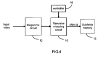
- a device for implementing the inventive method is shown at figure 4.
- This device comprises a recursive encoding circuit 10 and a controller 11 for controlling said circuit.
- the recursive encoding circuit 10 receives video coming from a degamma circuit 12 and outputs subfield code words SF[15:0] in a subfields memory 13.
- the circuit 10 applies also a dithering function to the data coming from a degamma circuit 12.
- a schematic diagram of the recursive encoding circuit 10 is given at figure 5. It comprises n encoding blocks, one for each subfield (n being the number of subfield).
- each subfield is denoted SF i , i being the number of the subfield.
- SF n designates the subfield with the highest weight (also denoted most significant subfield) and SF 1 designates the subfield with the lowest weight (also denoted least significant subfield).
- Each encoding block receives from the controller 11 the switching value SV i associated to the subfield SF i that it encodes and a luminance value coming from the preceding encoding block or the degamma circuit and outputs a subfield code bit B i corresponding to the subfield SF i and a remaining luminance value RV i to be encoded by the following encoding blocks.
- the subfield code bit B i is stored in the subfields memory 13.
- the encoding block associated to the subfield SF n receives luminance value coming from the degamma circuit 12 and the switching value of the subfield SF n from the controller 11 and outputs a subfield code bit B n and the remaining luminance value RV n to be encoded by the following encoding blocks.
- the encoding block associated to the subfield SF i , i ⁇ [2...n-1] receives the remaining luminance value RV i and the associated switching value SV i from the controller 11 and outputs the subfield code bit B i and the remaining luminance value RV i to be encoded by the following encoding blocks.
- the last encoding block associated to the subfield SF 1 receives the remaining luminance value RV 2 and the switching value SV 1 and outputs the subfield code bit B 1 .
- FIG. 6 A possible schematic diagram of the encoding block associated to the subfield SF i , i ⁇ [2...n], is shown at figure 6. It comprises :
- FIG. 7 A possible schematic diagram of the encoding block associated to the subfield SF 1 is shown at figure 7. It comprises :
Landscapes
- Engineering & Computer Science (AREA)
- Physics & Mathematics (AREA)
- Computer Hardware Design (AREA)
- General Physics & Mathematics (AREA)
- Theoretical Computer Science (AREA)
- Multimedia (AREA)
- Signal Processing (AREA)
- Control Of Indicators Other Than Cathode Ray Tubes (AREA)
- Transforming Electric Information Into Light Information (AREA)
- Liquid Crystal Display Device Control (AREA)
- Control Of Gas Discharge Display Tubes (AREA)
Priority Applications (7)
| Application Number | Priority Date | Filing Date | Title |
|---|---|---|---|
| EP05291973A EP1768087A1 (fr) | 2005-09-22 | 2005-09-22 | Procédé récursive et dispositif pour coder des valeurs de luminance dans des mots codés de sous-trames dans un dispositif d'affichage |
| EP06120447A EP1768088A3 (fr) | 2005-09-22 | 2006-09-11 | Procédé et dispositif pour coder des valeurs de luminance dans des mots codés de sous-trames dans un dispositif d'affichage |
| US11/522,767 US7804509B2 (en) | 2005-09-22 | 2006-09-18 | Method and device for encoding luminance values into subfield code words in a display device |
| KR1020060091187A KR101366071B1 (ko) | 2005-09-22 | 2006-09-20 | 디스플레이 디바이스에서 휘도 값을 서브필드 코드 워드로 인코딩하기 위한 방법 및 디바이스 |
| CN200610154327XA CN1937712B (zh) | 2005-09-22 | 2006-09-20 | 用于在显示设备中将亮度值编码成子场码字的方法及设备 |
| JP2006256017A JP5250191B2 (ja) | 2005-09-22 | 2006-09-21 | 表示装置で輝度値をサブフィールド符号語に符号化するための方法及び装置 |
| JP2012240030A JP5686786B2 (ja) | 2005-09-22 | 2012-10-31 | 表示装置で輝度値をサブフィールド符号語に符号化するための方法及び装置 |
Applications Claiming Priority (1)
| Application Number | Priority Date | Filing Date | Title |
|---|---|---|---|
| EP05291973A EP1768087A1 (fr) | 2005-09-22 | 2005-09-22 | Procédé récursive et dispositif pour coder des valeurs de luminance dans des mots codés de sous-trames dans un dispositif d'affichage |
Publications (1)
| Publication Number | Publication Date |
|---|---|
| EP1768087A1 true EP1768087A1 (fr) | 2007-03-28 |
Family
ID=35781276
Family Applications (1)
| Application Number | Title | Priority Date | Filing Date |
|---|---|---|---|
| EP05291973A Withdrawn EP1768087A1 (fr) | 2005-09-22 | 2005-09-22 | Procédé récursive et dispositif pour coder des valeurs de luminance dans des mots codés de sous-trames dans un dispositif d'affichage |
Country Status (5)
| Country | Link |
|---|---|
| US (1) | US7804509B2 (fr) |
| EP (1) | EP1768087A1 (fr) |
| JP (2) | JP5250191B2 (fr) |
| KR (1) | KR101366071B1 (fr) |
| CN (1) | CN1937712B (fr) |
Families Citing this family (6)
| Publication number | Priority date | Publication date | Assignee | Title |
|---|---|---|---|---|
| EP2006829A1 (fr) * | 2007-06-18 | 2008-12-24 | Deutsche Thomson OHG | Procédé et dispositif pour coder des niveaux vidéo dans un mot de code de sous-trame |
| CN101908313B (zh) * | 2010-08-02 | 2012-10-17 | 福州大学 | 多路脉宽调制数字显示系统功率动态均衡的方法及装置 |
| JP5906631B2 (ja) * | 2011-09-22 | 2016-04-20 | ソニー株式会社 | 表示装置、表示方法および電子機器 |
| US8947475B2 (en) * | 2011-10-25 | 2015-02-03 | Texas Instruments Incorporated | Spatially multiplexed pulse width modulation |
| US20130278834A1 (en) * | 2012-04-20 | 2013-10-24 | Samsung Electronics Co., Ltd. | Display power reduction using extended nal unit header information |
| KR20210009256A (ko) | 2019-07-16 | 2021-01-26 | 삼성전자주식회사 | 전계발광 디스플레이 장치 및 전계발광 디스플레이 장치의 휘도 보정 방법 |
Citations (7)
| Publication number | Priority date | Publication date | Assignee | Title |
|---|---|---|---|---|
| US5596349A (en) * | 1992-09-30 | 1997-01-21 | Sanyo Electric Co., Inc. | Image information processor |
| EP0822536A2 (fr) * | 1996-07-29 | 1998-02-04 | Fujitsu Limited | Procédé et dispositif pour l'affichage d'image en demi-teinte |
| EP0973147A1 (fr) * | 1997-03-31 | 2000-01-19 | Matsushita Electronics Corporation | Procede de visualisation du premier plan d'images et dispositif connexe |
| US6069609A (en) * | 1995-04-17 | 2000-05-30 | Fujitsu Limited | Image processor using both dither and error diffusion to produce halftone images with less flicker and patterns |
| US6100859A (en) * | 1995-09-01 | 2000-08-08 | Fujitsu Limited | Panel display adjusting number of sustaining discharge pulses according to the quantity of display data |
| WO2005041162A1 (fr) * | 2003-10-15 | 2005-05-06 | Thomson Licensing | Procede et dispositif servant a traiter des images video a afficher sur un ecran |
| WO2005059879A1 (fr) * | 2003-12-17 | 2005-06-30 | Thomson Licensing | Procede et dispositif permettant de reduire l'effet de charge |
Family Cites Families (14)
| Publication number | Priority date | Publication date | Assignee | Title |
|---|---|---|---|---|
| JPH09218662A (ja) * | 1996-02-14 | 1997-08-19 | Pioneer Electron Corp | 自発光画像表示パネルの駆動方法 |
| FR2745410B1 (fr) * | 1996-02-27 | 1998-06-05 | Thomson Csf | Procede de commande d'un ecran de visualisation d'image affichant des demi-teintes, et dispositif de visualisation mettant en oeuvre le procede |
| JP3642689B2 (ja) * | 1998-12-08 | 2005-04-27 | 富士通株式会社 | プラズマディスプレイパネル装置 |
| JP4406743B2 (ja) * | 1999-06-30 | 2010-02-03 | 株式会社日立プラズマパテントライセンシング | プラズマディスプレイ装置 |
| US6559816B1 (en) * | 1999-07-07 | 2003-05-06 | Lg Electronics Inc. | Method and apparatus for erasing line in plasma display panel |
| JP2001067041A (ja) * | 1999-08-31 | 2001-03-16 | Nec Corp | プラズマディスプレイの駆動装置、プラズマディスプレイのサブフィールド変換方法、およびプラズマディスプレイ装置 |
| JP3724301B2 (ja) * | 1999-12-09 | 2005-12-07 | セイコーエプソン株式会社 | 電気光学装置の駆動方法、その駆動回路、電気光学装置および電子機器 |
| US6388661B1 (en) * | 2000-05-03 | 2002-05-14 | Reflectivity, Inc. | Monochrome and color digital display systems and methods |
| TW490701B (en) * | 2001-04-04 | 2002-06-11 | Acer Display Tech Inc | Brightness compensation method for plasma display |
| JP4410997B2 (ja) * | 2003-02-20 | 2010-02-10 | パナソニック株式会社 | 表示パネルの駆動装置 |
| JP2005031467A (ja) * | 2003-07-07 | 2005-02-03 | Nec Plasma Display Corp | サブフィールドコーディング装置、その方法及びプラズマ表示装置 |
| KR100589379B1 (ko) * | 2003-10-16 | 2006-06-13 | 삼성에스디아이 주식회사 | 플라즈마 디스플레이 패널 구동 장치 및 그 계조 구현 방법 |
| EP1544837A1 (fr) * | 2003-12-17 | 2005-06-22 | Deutsche Thomson-Brandt Gmbh | Méthode et dispositif pour réduir les effets des differences de charge des lignes de balayage |
| CN1670799A (zh) | 2005-04-18 | 2005-09-21 | 彩虹集团电子股份有限公司 | 一种提高ac pdp图像质量的处理方法 |
-
2005
- 2005-09-22 EP EP05291973A patent/EP1768087A1/fr not_active Withdrawn
-
2006
- 2006-09-18 US US11/522,767 patent/US7804509B2/en not_active Expired - Fee Related
- 2006-09-20 CN CN200610154327XA patent/CN1937712B/zh not_active Expired - Fee Related
- 2006-09-20 KR KR1020060091187A patent/KR101366071B1/ko active IP Right Grant
- 2006-09-21 JP JP2006256017A patent/JP5250191B2/ja not_active Expired - Fee Related
-
2012
- 2012-10-31 JP JP2012240030A patent/JP5686786B2/ja not_active Expired - Fee Related
Patent Citations (7)
| Publication number | Priority date | Publication date | Assignee | Title |
|---|---|---|---|---|
| US5596349A (en) * | 1992-09-30 | 1997-01-21 | Sanyo Electric Co., Inc. | Image information processor |
| US6069609A (en) * | 1995-04-17 | 2000-05-30 | Fujitsu Limited | Image processor using both dither and error diffusion to produce halftone images with less flicker and patterns |
| US6100859A (en) * | 1995-09-01 | 2000-08-08 | Fujitsu Limited | Panel display adjusting number of sustaining discharge pulses according to the quantity of display data |
| EP0822536A2 (fr) * | 1996-07-29 | 1998-02-04 | Fujitsu Limited | Procédé et dispositif pour l'affichage d'image en demi-teinte |
| EP0973147A1 (fr) * | 1997-03-31 | 2000-01-19 | Matsushita Electronics Corporation | Procede de visualisation du premier plan d'images et dispositif connexe |
| WO2005041162A1 (fr) * | 2003-10-15 | 2005-05-06 | Thomson Licensing | Procede et dispositif servant a traiter des images video a afficher sur un ecran |
| WO2005059879A1 (fr) * | 2003-12-17 | 2005-06-30 | Thomson Licensing | Procede et dispositif permettant de reduire l'effet de charge |
Also Published As
| Publication number | Publication date |
|---|---|
| KR20070033901A (ko) | 2007-03-27 |
| US7804509B2 (en) | 2010-09-28 |
| CN1937712A (zh) | 2007-03-28 |
| JP5250191B2 (ja) | 2013-07-31 |
| US20070064019A1 (en) | 2007-03-22 |
| JP2007086788A (ja) | 2007-04-05 |
| JP5686786B2 (ja) | 2015-03-18 |
| JP2013033285A (ja) | 2013-02-14 |
| KR101366071B1 (ko) | 2014-02-21 |
| CN1937712B (zh) | 2013-09-25 |
Similar Documents
| Publication | Publication Date | Title |
|---|---|---|
| KR100521717B1 (ko) | 디스플레이 구동 장치 | |
| EP1768087A1 (fr) | Procédé récursive et dispositif pour coder des valeurs de luminance dans des mots codés de sous-trames dans un dispositif d'affichage | |
| US20060098024A1 (en) | Digital video signal data processor | |
| US20070222707A1 (en) | Method and Apparatus for Generating a Look-Up Table in the Video Picture Field | |
| EP1548696B1 (fr) | Méthode et dispositif de commande d'un panneau d'affichage à plasma | |
| US6989804B2 (en) | Method and apparatus for processing video pictures, especially for improving grey scale fidelity portrayal | |
| JP5049445B2 (ja) | 表示装置およびその駆動方法 | |
| EP0919984B1 (fr) | Procédé et dispositif de balayage d'un panneau a plasma | |
| EP1768088A2 (fr) | Procédé et dispositif pour coder des valeurs de luminance dans des mots codés de sous-trames dans un dispositif d'affichage | |
| US8212844B2 (en) | Method and device for encoding video levels into subfield code words | |
| EP1353315A1 (fr) | Procédé et dispositif d'amélioration de la résolution en niveau de gris d'un dispositif d'affichage d'images | |
| EP1638067A1 (fr) | Procédé et dispositif pour générer des codes de sous-trames | |
| EP1630772A1 (fr) | Procédé et dispositif de tremblement de demi-teinte | |
| EP1695328B1 (fr) | Procède et dispositif permettant de réduire l'effet de charge sur une ligne | |
| US20040125049A1 (en) | Method and apparatus for grayscale enhancement of a display device | |
| KR100610494B1 (ko) | 플라즈마 디스플레이 패널에서의 노이즈 저감 장치 및 그방법 | |
| JP3534018B2 (ja) | 表示装置の誤差拡散処理方法 | |
| EP1544838A1 (fr) | Méthode et dispositif pour réduire les effets des différences de charge des sous trames | |
| KR101431620B1 (ko) | 플라즈마 디스플레이 패널의 역감마 보정방법 | |
| US20060050017A1 (en) | Plasma display apparatus and image processing method thereof | |
| EP1638068A1 (fr) | Procédé et dispositif pour générer des codes de sous-trames | |
| EP1387342A2 (fr) | Méthode et dispositif pour améliorer l'échelle de gris d'un dispositif d'affichage |
Legal Events
| Date | Code | Title | Description |
|---|---|---|---|
| PUAI | Public reference made under article 153(3) epc to a published international application that has entered the european phase |
Free format text: ORIGINAL CODE: 0009012 |
|
| AK | Designated contracting states |
Kind code of ref document: A1 Designated state(s): AT BE BG CH CY CZ DE DK EE ES FI FR GB GR HU IE IS IT LI LT LU LV MC NL PL PT RO SE SI SK TR |
|
| AX | Request for extension of the european patent |
Extension state: AL BA HR MK YU |
|
| STAA | Information on the status of an ep patent application or granted ep patent |
Free format text: STATUS: THE APPLICATION HAS BEEN WITHDRAWN |
|
| 18W | Application withdrawn |
Effective date: 20070918 |